Teledyne Welding Consumables 7600 Users Manual M7600
7600 to the manual 314e91ec-001d-40d0-b8e2-c4faae13aae3
2015-02-03
: Teledyne Teledyne-Welding-Consumables-7600-Users-Manual-464586 teledyne-welding-consumables-7600-users-manual-464586 teledyne pdf
Open the PDF directly: View PDF ![]() .
.
Page Count: 126 [warning: Documents this large are best viewed by clicking the View PDF Link!]
Teledyne Analytical Instruments
OPERATING INSTRUCTIONS FOR
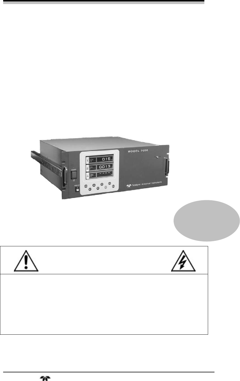
Model 7600
NDIR Infrared Gas Analyzer
DANGER
Toxic gases and or flammable liquids may be present in this monitoring system.
Personal protective equipment may be required when servicing this instrument.
Hazardous voltages exist on certain components internally which may persist
for a time even after the power is turned off and disconnected.
Only authorized personnel should conduct maintenance and/or servicing.
Before conducting any maintenance or servicing, consult with authorized
supervisor/manager.
P/N M7600
ECO:

Model 7600
Teledyne Analytical Instruments ii
Copyright © 2005 Teledyne Instruments/ Analytical Instruments
All Rights Reserved. No part of this manual may be reproduced, transmitted, transcribed,
stored in a retrieval system, or translated into any other language or computer language in
whole or in part, in any form or by any means, whether it be electronic, mechanical,
magnetic, optical, manual, or otherwise, without the prior written consent of Teledyne
Instruments/ Analytical Instruments, 16830 Chestnut Street, City of Industry, CA 91749-
1580.
Warranty
This equipment is sold subject to the mutual agreement that it is warranted by us free from
defects of material and of construction, and that our liability shall be limited to replacing or
repairing at our factory (without charge, except for transportation), or at customer plant at
our option, any material or construction in which defects become apparent within one year
from the date of shipment, except in cases where quotations or acknowledgements provide
for a shorter period. Components manufactured by others bear the warranty of their
manufacturer. This warranty does not cover defects caused by wear, accident, misuse,
neglect or repairs other than those performed by TI/AI or an authorized service center. We
assume no liability for direct or indirect damages of any kind and the purchaser by the
acceptance of the equipment will assume all liability for any damage which may result from
its use or misuse.
We reserve the right to employ any suitable material in the manufacture of our apparatus,
and to make any alterations in the dimensions, shape or weight of any parts, in so far as
such alterations do not adversely affect our warranty.
Important Notice
This instrument provides measurement readings to its user, and serves as a tool by which
valuable data can be gathered. The information provided by the instrument may assist the user
in eliminating potential hazards caused by his process; however, it is essential that all
personnel involved in the use of the instrument or its interface, with the process being
measured, be properly trained in the process itself, as well as all instrumentation related to it.
The safety of personnel is ultimately the responsibility of those who control process
conditions. While this instrument may be able to provide early warning of imminent
danger, it has no control over process conditions, and it can be misused. In particular, any
alarm or control systems installed must be tested and understood, both as to how they
operate and as to how they can be defeated. Any safeguards required such as locks, labels,
or redundancy, must be provided by the user or specifically requested of TI/AI at the time
the order is placed.
Therefore, the purchaser must be aware of the hazardous process conditions. The purchaser
is responsible for the training of personnel, for providing hazard warning methods and
instrumentation per the appropriate standards, and for ensuring that hazard warning devices
and instrumentation are maintained and operated properly.
Teledyne Instruments/ Analytical Instruments, the manufacturer of this instrument, cannot
accept responsibility for conditions beyond its knowledge and control. No statement
expressed or implied by this document or any information disseminated by the
manufacturer or its agents, is to be construed as a warranty of adequate safety control under
the user’s process conditions.

Infrared Gas Analyzer
Teledyne Analytical Instruments iii
Specific Model Information
Instrument Serial Number: _______________________
Instrument Range: _______________
Calibrated for: _______________
Background Gas: _______________
Zero Gas: _______________
Span Gas: _______________
Model 7600
Teledyne Analytical Instruments iv
Safety Messages
Your safety and the safety of others is very important. We have
provided many important safety messages in this manual. Please read
these messages carefully.
A safety message alerts you to potential hazards that could hurt you
or others. Each safety message is associated with a safety alert symbol.
These symbols are found in the manual and inside the instrument. The
definition of these symbols is described below:
GENERAL WARNING/CAUTION: Refer to the instructions
for details on the specific danger. These cautions warn of
specific procedures which if not followed could cause bodily
Injury and/or damage the instrument.
CAUTION: HOT SURFACE WARNING: This warning is
specific to heated components within the instrument. Failure
to heed the warning could result in serious burns to skin and
underlying tissue.
WARNING: ELECTRICAL SHOCK HAZARD: Dangerous
voltages appear within this instrument. This warning is
specific to an electrical hazard existing at or nearby the
component or procedure under discussion. Failure to heed this
warning could result in injury and/or death from
electrocution.
Technician Symbol: All operations marked with this symbol
are to be performed by qualified maintenance personnel only.
NOTE: Additional information and comments regarding a
specific component or procedure are highlighted in the form
of a note.
CAUTION: THE ANALYZER SHOULD ONLY BE USED FOR THE
PURPOSE AND IN THE MANNER DESCRIBED IN
THIS MANUAL.
No
Symbol

Infrared Gas Analyzer
Teledyne Analytical Instruments v
IF YOU USE THE ANALYZER IN A MANNER OTHER
THAN THAT FOR WHICH IT WAS INTENDED,
UNPREDICTABLE BEHAVIOR COULD RESULT
POSSIBLY ACCOMPANIED WITH HAZARDOUS
CONSEQUENCES.
This manual provides information designed to guide you through
the installation, calibration operation and maintenance of your new
analyzer. Please read this manual and keep it available.
Occasionally, some instruments are customized for a particular
application or features and/or options added per customer requests.
Please check the front of this manual for any additional information in
the form of an Addendum which discusses specific information,
procedures, cautions and warnings that may be peculiar to your
instrument.
Manuals do get lost. Additional manuals can be obtained from
TI/AI at the address given in the Appendix. Some of our manuals are
available in electronic form via the internet. Please visit our website at:
www.teledyne-ai.com.

Model 7600
Teledyne Analytical Instruments vi
Table of Contents
List of Figures ............................................................................... x
List of Tables............................................................................... xii
Introduction ................................................................................. 15
1.1 Overview 15
1.2 Main Features of the Analyzer 15
1.3 Options Available 17
1.4 Applications 17
1.5 Description of the Main Unit 18
Installation ................................................................................... 21
2.1 Unpacking the Analyzer 21
2.2 Choosing a Location 22
2.3 Mounting the Analyzer 23
2.4 Mounting the Input/Output Terminal Module 23
2.5 Gas Connections 25
2.5.1 Internal Piping Diagram 25
2.5.2 External Piping Diagram 27
2.5.3 Gas Conditioning 28
2.5.4 Flowrate 29
2.5.5 Preparation of Calibration Gas 29
2.5.6 Purging the Analyzer 30
2.5.7 Sample Gas Pressure 30
2.5.8 Example configuration of gas sampling system 30
2.6 Electrical Connections 32
2.6.1 Power Inlet 32
2.6.2 Input/Output Terminal Module 33
2.7 Testing the System 34

Infrared Gas Analyzer
Teledyne Analytical Instruments vii
Operation .....................................................................................35
3.1 General Information 35
3.2 Display and Available Menus 36
3.3 The Display Screen 38
3.3.1 Measurement Mode 38
3.3.2 Setting/Selection Screen 40
3.4 Basic Operation 41
3.5 Setting Up the Analyzer in the User Mode 42
3.5.1 Switch Ranges 42
3.5.1.1 Manual Range Switching 43
3.5.1.2 Range identification contact operation 44
3.5.1.3 Remote Range Selection 45
3.5.1.4 Autoranging 46
3.5.2 Calibration Parameters 46
3.5.2.1 Calibration Value 46
3.5.2.2 Setting of Manual Zero Calibration 48
3.5.2.3 Setting of calibration range 50
3.5.2.4 Setting of auto calibration component/range 51
3.5.3 Alarm Setting 53
3.5.3.1 Configuring the Alarms 55
3.5.3.2 Hysteresis Setting 56
3.5.4 Setting of Auto Calibration 58
3.5.4.1 Auto Calibration 58
3.5.4.2 Gas Flow Time Setting 59
3.5.4.3 Cycle Setting Range 60
3.5.4.4 Remote Start 62
3.5.4.5 Forced Run/Stop of Auto Calibration 62
3.5.5 Setting of Auto Zero Calibration 65
3.5.5.1 Auto Zero Calibration 65
3.5.5.2 Forced run/stop of auto zero calibration 68
3.5.6 Peak Alarm Setting 70
3.5.7 Parameter Setting 73

Model 7600
Teledyne Analytical Instruments viii
3.5.7.1 Output Hold 75
3.5.7.2 Average Value Reset: 78
3.5.7.3 Response Time 79
3.5.7.4 Average Period 79
3.5.7.5 Backlight Timer 80
3.5.7.6 Maintenance mode 81
3.6 Maintenance Mode 82
3.6.1 Sensor Input Value 83
3.6.2 Error Log 84
3.6.3 Calibration Log 84
3.6.4 Optical Adjustment 85
3.6.5 Moisture Interference Adjustment 86
3.6.6 Output Adjustment Screen 86
3.6.7 Other Parameters 87
3.7 Calibration 90
3.7.1 Zero Calibration 90
3.7.2 Span Calibration 91
Maintenance ................................................................................ 93
4.1 Routine Maintenance 93
4.2 Daily Check and Maintenance Procedures 93
4.3 Analyzer Maintenance 94
4.3.1 Sample Cell Cleaning 94
4.3.2 Cleaning the Cell Block 97
4.4 Optical Zero Adjustment 99
4.5 Moisture Interference Compensation Adjustment 102
4.6 Error Messages 104
4.6.1 Error Log File 106
4.6.2 Error Log Screen 106
4.6.3 Deleting Error Hstory 107
Appendix.................................................................................... 109
A.1 SPECIFICATIONS 109
A.2 Standard Functions 111

Infrared Gas Analyzer
Teledyne Analytical Instruments ix
A.3 Optional Functions 115
A.4 Performance: 116
A.5 Standard Requirements for Sample Gas 117
A.6 Installation Requirements 118
A.7 EC Directive Compliance 118
A.8 Terminal Block Connections 119
A.9 Description on Terminal Block 120
Index...........................................................................................125

Model 7600
Teledyne Analytical Instruments x
List of Figures
Figure 1-1: Model 7600A Infrared Gas Analyzer........................... 16
Figure 1-2: Model 7600 Description .............................................. 19
Figure 2-1: Slide Rail Mounting Dimensions ................................. 23
Figure 2-2: Input/Output Terminal Module..................................... 24
Figure 2-3: Mounting the I/O Module............................................. 24
Figure 2-4: Internal Piping with Single or Dual Measuring Units ... 26
Figure 2-5: External Piping with Single Inlet and Outlet ................ 27
Figure 2-6: External Piping with Two Pair of Inlet/Outlet (1).......... 28
Figure 2-7: External Piping with Two Pair of Inlet/Outlet (2).......... 28
Figure 2-8: Five Component Analysis System .............................. 31
Figure 2-9: Model 7600 Electrical Connections............................. 32
Figure 2-10: Noise Suppression.................................................... 33
Figure 2-11: I/O Cable Connection................................................ 33
Figure 3-1: Front Panel of the Model 7600.................................... 35
Figure 3-2: Interface Keys on the Front Panel............................... 35
Figure 3-3: Display Modes and Menu Hierarchy ........................... 37
Figure 3-4: Example Screen—5 Component Analysis 12
Channels................................................................................ 38
Figure 3-5: Setting/Selection Screen Areas .................................. 41
Figure 3-6: Hysteresis Example for a High Limit Alarm................. 57
Figure 3-7: Example Auto Calibration ........................................... 61
Figure 3-8: Example Auto Zero Calibration ................................... 67
Figure 3-9: Peak Alarm Example .................................................. 72
Figure 3-10: Output Hold for Manual Calibration........................... 75

Infrared Gas Analyzer
Teledyne Analytical Instruments xi
Figure 3-11: Output Hold for Auto Calibration ...............................76
Figure 3-12: Output Hold for External Hold ...................................76
Figure 3-13: Average Value Reset ................................................79
Figure 3-14: Example Average Period ..........................................80
Figure 4-1: Top Cover Removal ....................................................95
Figure 4-2: Sample Cell Removal..................................................95
Figure 4-3: Sample Cell.................................................................96
Figure 4-4: IR Window Assembly ..................................................97
Figure 4-5: Detector Secure Nut....................................................98
Figure 4-6: Cell Block Assembly....................................................99
Figure 4-7: Optical Adjustment Display for Dual Optical System
Option...................................................................................100
Figure 4-8: Optical Zero Adjustment............................................101
Figure 4-9: Beam Adjustment Plate.............................................102
Figure 4-10: Bubbler Apparatus ..................................................103
Figure 4-11: The Error Log Screen..............................................107

Model 7600
Teledyne Analytical Instruments xii
List of Tables
Table 2-1: Correspondence of Measured Components and
Measuring Units ..................................................................... 27
Table 2-2: Zero and Span Gas...................................................... 29
Table 4.1 Troubleshooting and Maintenance ................................ 93
Table 4-2: Components of Optical Adjustment Screen ............... 100
Table 4-3: Error Messages.......................................................... 104
Infrared Gas Analyzer
Teledyne Analytical Instruments xiii
DANGER
COMBUSTIBLE GAS USAGE
WARNING
This is a general purpose instrument designed for use in a
non-hazardous area. It is the customer's responsibility to
ensure safety especially when combustible gases are being
analyzed since the potential of gas leaks always exist.
The customer should ensure that the principles of operating
this equipment are well understood by the user. Misuse of
this product in any manner, tampering with its components,
or unauthorized substitution of any component may
adversely affect the safety of this instrument.
Since the use of this instrument is beyond the control of
Teledyne Instruments/ Analytical Instruments, referred as
TI/AI, no responsibility by TI/AI, its affiliates, and agents for
damage or injury from misuse or neglect of this equipment is
implied or assumed.

Model 7600
Teledyne Analytical Instruments xiv

Infrared Gas Analyzer Introduction
Teledyne Analytical Instruments 15
Introduction
1.1 Overview
The Model 7600 Infrared Gas Analyzer is a microprocessor based
infrared gas analyzer used to measure the concentration of NO, SO2,
CO2, CO and CH4 contained in sample gas. It is based on the principle
that different molecular species have unique absorption spectrum in the
infrared, and the intensity of absorption is determined by the Lambert-
Beer law.
In addition to the infrared analyzer, the Model 7600 can also be
equipped with a built-in compact paramagnetic O2 sensor or employ an
external zirconia oxygen sensor to increase to 5 the number of
simultaneous component species the unit can analyze.
Teledyne's Series 7600 Infrared (IR) Gas Analyzer is conveniently
packaged in either a 19" rack mount or NEMA-4 wall mount enclosure.
The NEMA-4 enclosure can be X or Z-purged to satisfy hazardous area
installation requirements.
A high-sensitivity mass flow type twin detector is used for infrared
measurements. By utilizing a single beam, double path design in
conjunction with a serial dual-layer transmission detector, the Series
7600 delivers long term, drift-free performance.
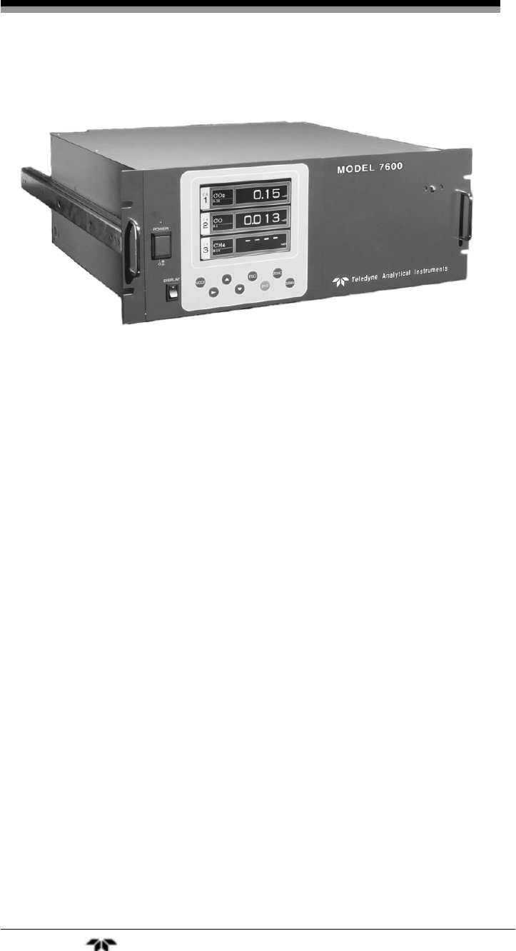
The concentration of the desired gases is displayed on a large, easy-
to-read back-lit LCD. Figure 1-1 shows the standard rack mountable
Model 7600. The user interface is very intuitive and the menu / mode
selection buttons, which are readily accessible, provide the operator with
dynamic control and extensive diagnostic capabilities.
1.2 Main Features of the Analyzer
The Model 7600 Infrared Gas Analyzer is designed for accurate
and reliable gas analysis and is easy to operate. The following features
are standard on the 7600 instrument:
Introduction Model 7600
Teledyne Analytical Instruments 16
Figure 1-1: Model 7600A Infrared Gas Analyzer
• Simultaneous measurement of up to five components
• Excellent long-term stability
• Large, easy to read LCD display showing all simultaneous
measurements and computations
• Slide-out, chassis design to facilitate any optical or
maintenance adjustments required to fine tune analyzer
performance (7600A)
• Multiple, in-depth on-screen analyzer functions easily
accessible using the front-panel user interface buttons
• Follow & Hold output signal control (during calibration)
• Remote range change control
• Low / Hi limit alarms
• Range ID signals
• Auto-calibration with user adjustable frequency and gas flow
time setting programming capabilities
• Remote auto-calibration initiation
• Auto-calibration status contacts

Infrared Gas Analyzer Introduction
Teledyne Analytical Instruments 17
• Instrument or calibration error contact outputs
• Extra functions included such as average value computation,
O2 conversion
• Pump ON/OFF contact
1.3 Options Available
• Percent O2 detector — Paramagnetic (built-in) or ZrO2
(externally installed), user preference
• O2 correction (the conversion of measured CO and SO2
readings into values at standard O2 concentration). Consult
factory for more detail for this function.
• Communication functions:
• RS-232C (9 pins D-Sub connector)
• Half-duplex bit serial
• Modbus protocol
1.4 Applications
The Model 7600 Infrared Gas Analyzer is a versatile analytical
instrument tool and is ideally suited for multi-parameter gas analysis
requirements for applications such as:
• Combustion control within the power, pulp and paper, steel,
and cement industries
• Heat treating / Inert gas blanketing atmosphere control
• Bulk-gas impurity analysis within the air separation industry
• Anaerobic digester / Bio-gas / Land-fill gas analysis
• Vent gas analysis of oxyhydrochlorination reactors (EDC)
• Off-gas analysis on PTA and Maleic Anhydride reactors
• Fluid Catalytic Cracker (FCC) regeneration gas analysis
• Ammonia / Fertilizer process gas stream analysis
• Continuous Emissions Monitoring Systems (CEMS)

Introduction Model 7600
Teledyne Analytical Instruments 18
• Biochemistry and fermentation,
• Automotive emission analysis
• Explosive and toxic gas analysis
• Chemical analysis
• Refinery operation
• Research applications
1.5 Description of the Main Unit
Teledyne's Series 7600 Infrared Gas Analyzer measures the
concentration of NO, SO2, CO2, CO, and CH4 in a gas mixture on a
continuous basis. The Series 7600 can also be supplied with an oxygen
sensor, which allows the simultaneous measurement of oxygen
concentration as well. The NEMA-4 enclosure can be X or Z-purged to
satisfy hazardous area installation requirements.
The system uses a high-sensitivity mass flow type twin detector for
infrared measurements. A single beam, double path optical bench is
installed in conjunction with a serial dual-layer transmission detector.
The concentration of the desired gases is displayed on a large, easy-
to-read backlit LCD. The user interface is very intuitive and the menu /
mode selection buttons, which are readily accessible, provide the
operator with dynamic control and extensive diagnostic capabilities. See
Figure 1-2.
The front panel mounted power switch turns the instrument on and
off while the display switch controls power to the display.
Front panel mounted handles make sliding the instrument out of the
panel rack or enclosure a simple task for easy maintenance.

Infrared Gas Analyzer Introduction
Teledyne Analytical Instruments 19
Figure 1-2: Model 7600 Description
Gas connections for the 7600 instrument are made on the rear panel
of the instrument using the ¼” NPT fittings installed. The standard
instrument has two measuring units and a pair of inlet/outlet gas
connections exist for each unit. See Section 2.5 Gas Connections.
A power receptacle on the rear panel accepts the three-prong power
cable supplied with the instrument. The Model 7600 operates on 100-
240 VAC 50/60 Hz power. The power inlet conforms to EN60320
Protection Class 1 specifications.

Introduction Model 7600
Teledyne Analytical Instruments 20
Infrared Gas Analyzer Installation
Teledyne Analytical Instruments 21
Installation
Installation of the analyzer includes:
1. Unpacking the system.
2. Choosing a suitable location
3. Mounting the analyzer
4. Mounting the terminal module
5. Installing gas connections
6. Making electrical connections
7. Testing the installation.
CAUTION: READ THIS CHAPTER IN ITS ENTIRETY BEFORE
INSTALLING THE SYSTEM.
FOR INDOOR USE ONLY.
2.1 Unpacking the Analyzer
The Model 7600 Infrared Gas Analyzer is shipped with the
following components:
• 7600 Analyzer
• Input/Output terminal module set
• Connection cable
• Power cable
• Fuse (2)
• Cell window mounting tool
• Slide rail (2)*
• Relay board for auto calibration*
• Relay board connection cable*
• Instruction manual

Installation Model 7600
Teledyne Analytical Instruments 22
* These optional items are included if specified at the time of purchase
As soon as you receive the instrument, carefully unpack and inspect
the analyzer and components for damage. Immediately report any
damage to the shipping agent. The analyzer is shipped with all the
materials you need to install and prepare the system for operation.
2.2 Choosing a Location
CAUTION: THIS UNIT IS NOT EXPLOSION-PROOF. DO NOT
INSTALL IT IN A LOCATION WHERE EXPLOSIVE OR
FLAMMABLE GASES ARE PRESENT.
Select an installation location that meets the following criteria:
• This instrument should be rack mounted, or mounted in a
steel enclosure.
• Indoor location.
• Vibration-free.
• Not exposed to direct sunlight.
• Clean and non-cluttered space.
• Depending on the options selected at the time of purchase,
the model 7600 requires an AC power source of 100V to
240V AC.
• Operating voltage: 85V to 264V AC
• Rated frequency: 50/60 Hz
• Power consumption: 250 VA max.
• Plug: Comformity to EN60320 class I type 3-pin inlet
• Operation conditions:
• Ambient temperature: -5° to 45°C
• Ambient humidity: 90 % RH or less, no condensation
Infrared Gas Analyzer Installation
Teledyne Analytical Instruments 23
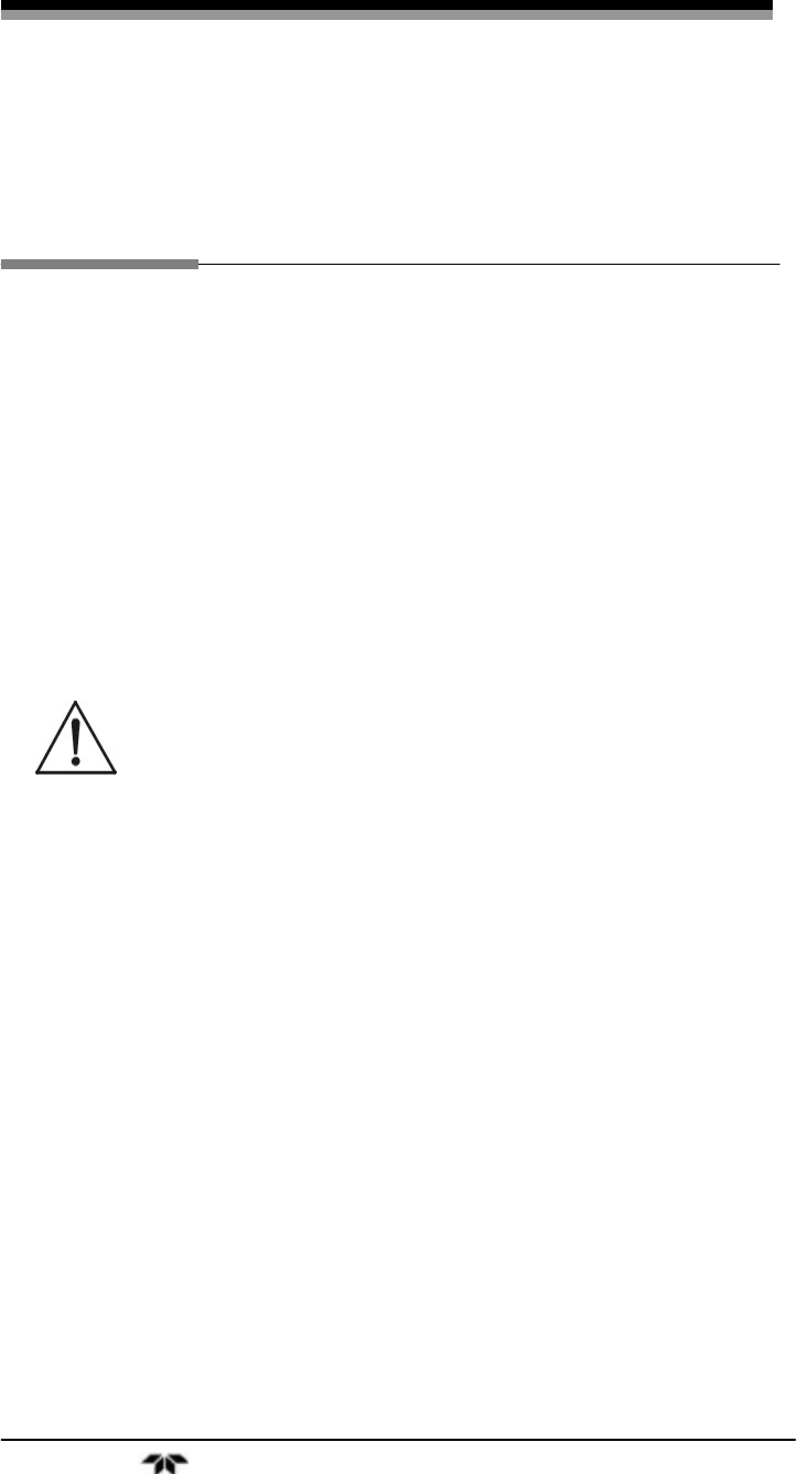
2.3 Mounting the Analyzer
The 19” rack mountable 7600 analyzer is designed for either a
guide rail or slide rail mounting within a rack or cabinet. The guide rail
method supports the weight of the instrument from the bottom and can
be used when there is adequate space for removing the top cover for
maintenance. The slide rail mount supports the instrument from sliders
mounted on the side of the instrument as shown in Figure 2-1. The
instrument is then able to slide out of the rack or enclosure for required
access during maintenance.
Figure 2-1: Slide Rail Mounting Dimensions
2.4 Mounting the Input/Output Terminal Module
The input/output module is the electronic interface that handles the
various signals to and from the analyzer. It consists of up to five
terminal blocks, a communications connector, a cable connector, and a
solenoid drive output connector mounted together on a single mounting
plate. See Figure 2-2.
Mount the input/output terminal module to the rack or cabinet panel
using the six M4 screws supplied. For grounding, see Figure 2-3.
Note: To avoid noise generated from external units, mount the
I/O terminal module mounting plate to the panel making
sure there is adequate metal contact for continuity at the

Installation Model 7600
Teledyne Analytical Instruments 24
mounting surface. Connect the panel to the same ground
as the analyzer main unit.
Figure 2-2: Input/Output Terminal Module
Figure 2-3: Mounting the I/O Module

Infrared Gas Analyzer Installation
Teledyne Analytical Instruments 25
2.5 Gas Connections
Gas connections are made on the rear panel of the analyzer. Adhere
to the following guidelines when making gas connections:
• Use a corrosion resistant tube such as Teflon, stainless or
polyethylene to connect the instrument to a sampling system.
Even if there is a danger of corrosion, refrain from using
rubber or soft vinyl tubing. This would result in instrument
inaccuracies due to gas absorption by the piping materials.
• Pipe connection port is Rc1/4 female thread (or NPT1/4).
Piping should be cut as short as possible for quicker
response. About 4 mm inner diameter is recommended.
• Keep out dust and debris from the tubing and connections .
Always use clean tubing and fittings.
Connect the gas tube as follows:
• Sample gas inlet: Attach the sample gas tube to the inlet
fitting. The sample gas should be filtered and dehumidified
before passing into the analyzer. This port is also used to
connect the zero and span calibration gases.
• The gas flow should be constant within the range of 0.5
L/min ±0.2 L/min.
• Sample gas outlet: Sample gas exits the analyzer through
the gas out port at atmospheric pressure. Exhaust gases must
be vented safely.
• Purge gas inlet: This connection is used for purging the
inside of the analyzer. Purging is not always required. See
Section 2.5.6 Purging the Analyzer. When required, use dry
N2 or instrumentation air for the purge gas. Use a flow rate of
1L/min or greater).
2.5.1 Internal Piping Diagram
Note: When the purge gas inlet is provided, an internal
connection to measuring unit 2 is installed.

Installation Model 7600
Teledyne Analytical Instruments 26
An internal piping diagram for an instrument with one or two
measuring units is shown in Figure 2-4. When there are two measuring
units, if a built-in oxygen sensor is used, it must be installed in
measuring unit 2. The diagram shows the combination of two cells used
in measuring unit #2. This is possible by combining ranges. When a
single measuring unit is used, there is only a single inlet and outlet gas
connection.
Figure 2-4: Internal Piping with Single or Dual Measuring Units
Depending on the options chosen, the analyzer can be configured in
several ways. Table 2-1 lists the possible configurations for single and
dual measuring units with 1 to 4 component meters.
Infrared Gas Analyzer Installation
Teledyne Analytical Instruments 27
Table 2-1: Correspondence of Measured Components and Measuring
Units
Measuring components Measuring unit 1 Measuring unit 2
1-component meter for NO,
SO2, CO2, CO and CH4 Each component None
2-component meter for
NO/SO2 and CO2
/
CO NO/SO2
CO2
/
CO None
2-component meter for
NO/CO NO CO
3-component meter for
NO/SO2/CO NO/SO2 CO
4-component meter for
NO/SO2/CO2/CO NO/SO2 CO2/CO
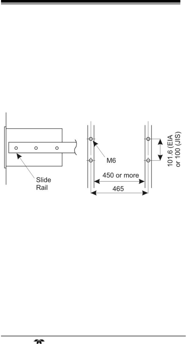
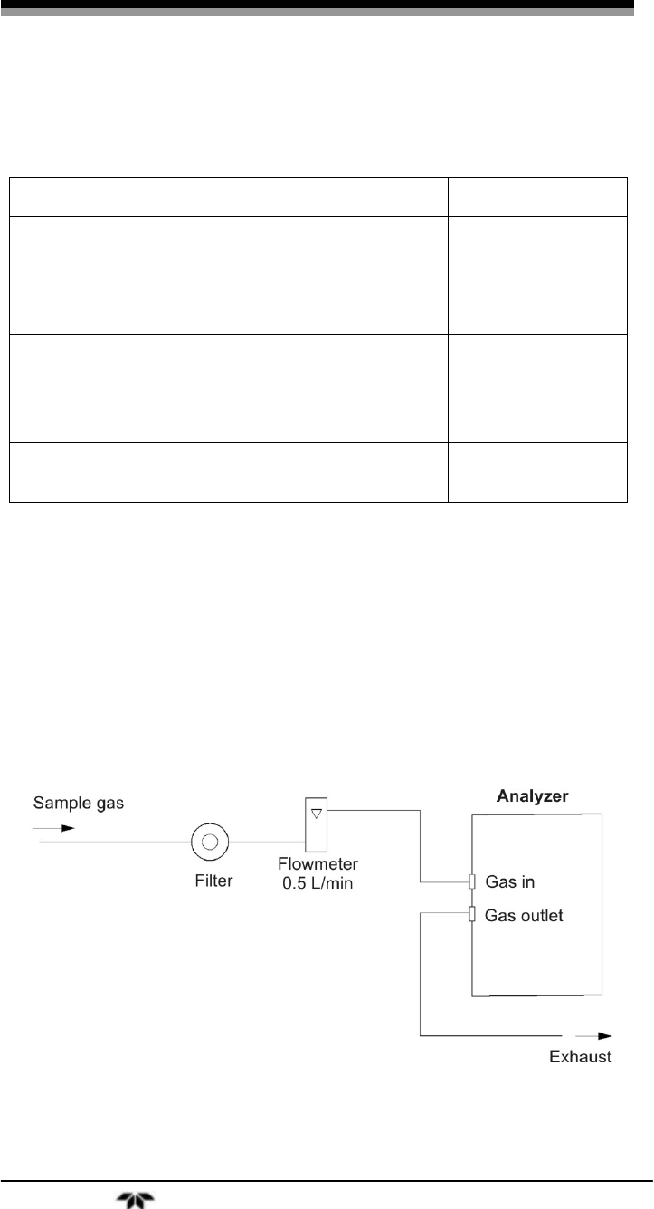
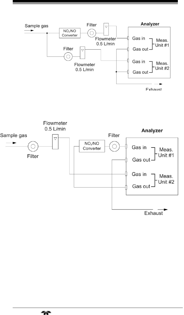
2.5.2 External Piping Diagram
There are several ways to bring sample gas to the analyzer
depending on the number of inlet/outlet gas connections on your
instrument Recommended piping diagrams are shown in Figures 2-5, 2-
6 and 2-7. Figure 2-5 is a schematic for an instrument with a single pair
of inlet/outlet gas connections. Figures 2-6 and 2-7 are used when there
are two pair of inlet/outlet connections. Note that a NO2/NO converter
is used when NO measurement is used for NOx analysis.
Figure 2-5: External Piping with Single Inlet and Outlet
Installation Model 7600
Teledyne Analytical Instruments 28
Figure 2-6: External Piping with Two Pair of Inlet/Outlet (1)
Figure 2-7: External Piping with Two Pair of Inlet/Outlet (2)
2.5.3 Gas Conditioning
For optimum performance, the sample gas should be treated as
follows:
• A filter should be installed to remove any dust or particles in
the sample gas. For a final stage filter, use a filter that can
remove dust particles of 0.3 μm.

Infrared Gas Analyzer Installation
Teledyne Analytical Instruments 29
• The dew point of the sample gas must be lower than the
ambient temperature to avoid condensation in the analyzer. If
vapor is contained in the sampling gas, the dew point should
be lowered to 0°C by using a dehumidifier.
• If SO2 mist is contained in the sample gas, use a mist filter or
cooler to remove the SO2 mist. Other mists should be
removed by using an appropriate mist filter or cooler.
• Corrosive gases such as Cl2, F2 and HCl, if contained in the
sample gas in considerable amounts, will shorten the life of
the instrument.
• Sample gas temperature should be within 0 to 50°C. Hot gas
should not be fed directly into the instrument.
2.5.4 Flowrate
Use a flowrate of 0.5L/min ±0.2L/min. The sample system should
be designed to avoid any flow fluctuation during measurement.
Use a flowmeter to observe the flow reading as shown in the
external piping diagrams of Figures 2.5, 2.6 and 2.7.
2.5.5 Preparation of Calibration Gas
Routine calibration using calibration gases is required for
optimizing the performance of this instrument. Once a week is a
suggested calibration frequency. Table 2-2 indicates the zero and span
gas required for calibration.
Table 2-2: Zero and Span Gas
Analyzer without
O2 Analyzer with built-in
O2 Analyzer with external
zirconia O2 sensor
Zero gas N2 gas N2 gas Dry air
Span gas
other than for
O2
t
Gas concentration
of 90% or more of
full scale
Gas concentration of
90% or more of full
scale
Gas concentration of 90%
or more of full scale
Span gas for
O2 analysis NA Gas concentration of
90% or more of full
scale
1 to 2% O2

Installation Model 7600
Teledyne Analytical Instruments 30
2.5.6 Purging the Analyzer
In general, purging the analyzer is not required unless one of the
following cases apply:
• A combustible gas component is contained in sample gas.
• Corrosive gas is contained in the atmospheric air at the
installation site.
• The same gas as the sample gas component is contained in
the atmospheric air at the installation site.
In the above situations, the inside of analyzer should be purged
with instrument air or N2. Use a purge flow rate of about 1 L/min.
Use a filter to remove dust or mist from the purge gas.
2.5.7 Sample Gas Pressure
The sample gas pressure at the outlet should be atmospheric
pressure.
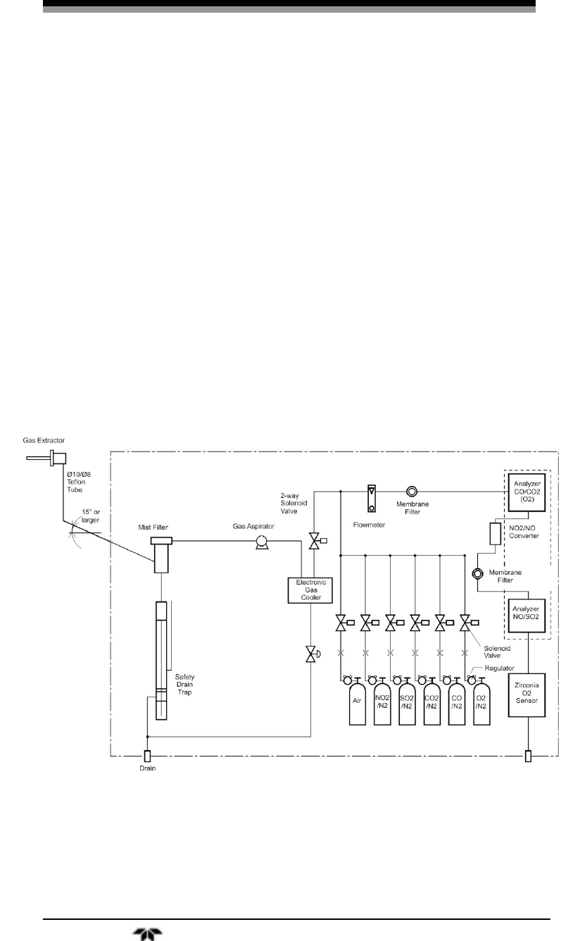
2.5.8 Example configuration of gas sampling system
A typical system configuration with five component gas analysis
for monitoring combustion exhaust gas from boiler, refuse incinerator,
etc. is shown in Figure 2-8. Contact Teledyne for specific application
system configuration or further information.
The system shown is comprised of:
• Model 7600—with dual measuring unit option and external
zirconia oxygen sensor.
• Gas Extractor—with stainless steel filter of standard mesh 40
μm equipped with integral heater.
• Mist Filter—to remove condensate, mist and dust from the
sample before it enters the analyzer.
• Safety Drain Trap—with two compartments for positive and
negative pressure. It monitors and adjusts the sample gas
pressure.
• Gas Aspirator—to aspirate the sample gas.
• Electronic Gas Cooler—used to dry the sample gas to a dew
point of approximately 2°C (35.6°F).
Infrared Gas Analyzer Installation
Teledyne Analytical Instruments 31
• Solenoid Valve—for introducing calibration gas and
OFF/ON flow of sample gas.
• Membrane Filter—PTFE filter for rempval of fine dust
particles.
• Flowmeter—adjusts and monitors the sample gas flowrate.
• Standard Gas—a bank of calibration gases used for setting
zero and span of the analyzer for each species monitored.
• Zirconia Sensor— an external zirconia sensor is used for
measuring the oxygen concentration in the sample gas. Some
instruments use a built-in paramagnetic oxygen sensor
instead aof an external zirconia sensor.
• NO2/NO Converter—added to the NO analysis circuit which
uses an efficient catalyst for converting NO2 to NO for
analysis.
Figure 2-8: Five-Component Analysis System
Installation Model 7600
Teledyne Analytical Instruments 32
2.6 Electrical Connections
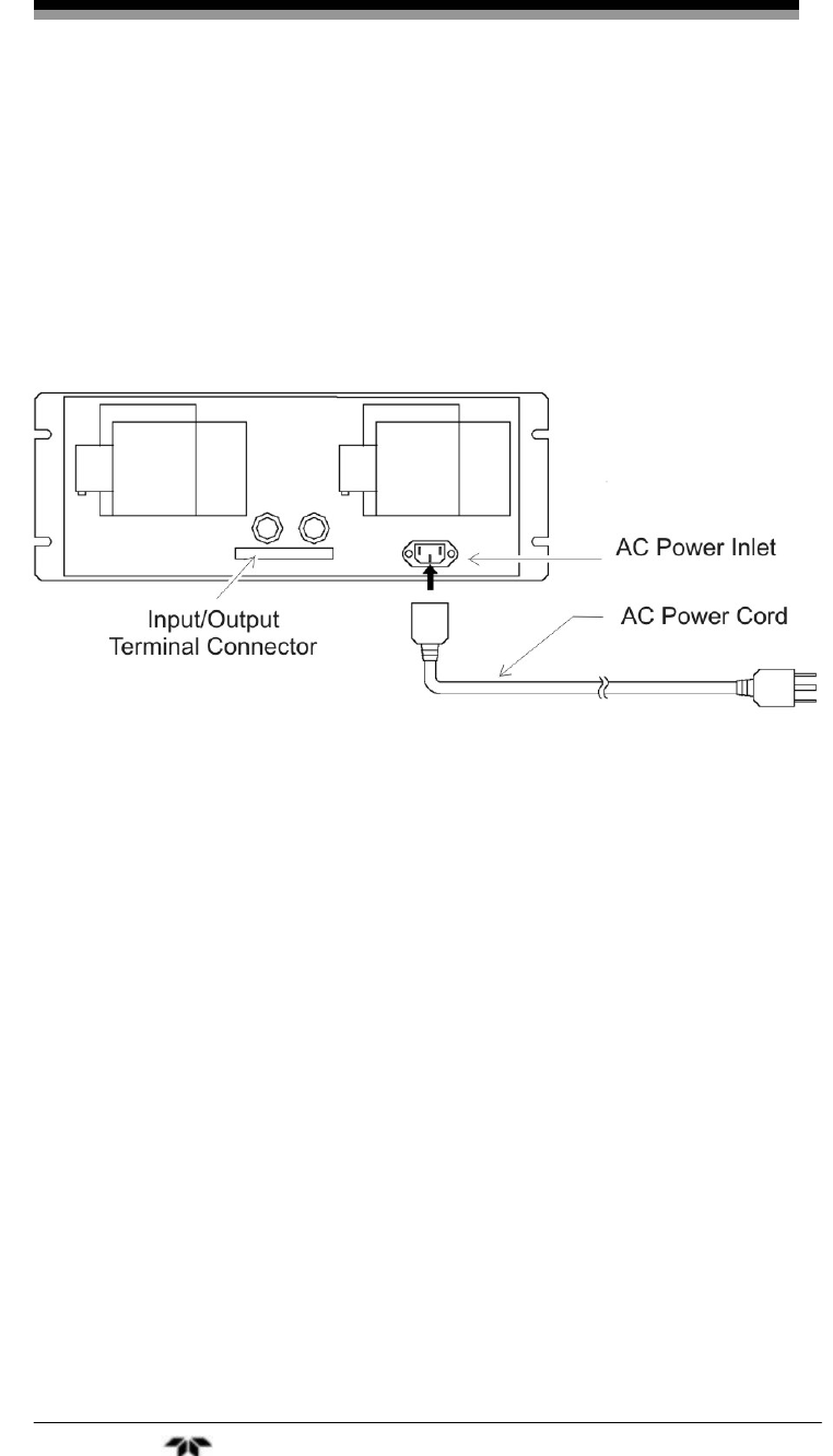
2.6.1 Power Inlet
The power inlet for the Model 7600 is located on the rear panel as
shown in Figure 2-9. The proper 3-prong power cord has been supplied
with your instrument. Connect the power cable to the power inlet.
Figure 2-9: Model 7600 Electrical Connections
The Model 7600 requires 100-240 VAC 50/60 Hz power.
Avoid installing this instrument near an electrical unit that
generates electrical noise such as a high frequency furnace or electric
welder. If using the instrument near such a noise-generating unit is
unavoidable, use a separate power line to avoid noise.
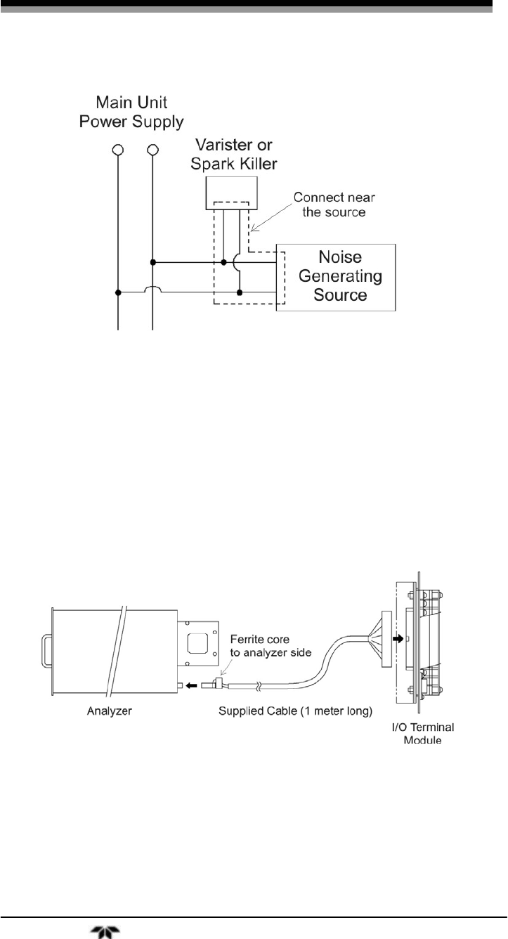
Mount a noise suppressor such as varister or spark killer as shown
in Figure 2-10 to the noise generating unit when noise is generated from
relays or solenoid valves. The suppressor must be mounted near the
noise generating source, or it will have no effect.
Infrared Gas Analyzer Installation
Teledyne Analytical Instruments 33
Figure 2-10: Noise Suppression
2.6.2 Input/Output Terminal Module
Use the supplied cable to interface the I/O Module to the analyzer.
Plug the cable connector into the receptacle at the rear panel of the
analyzer and the receptacle on the PC board of the input/output module.
Make sure that the ferrite core attached to the I/O cable goes to the
analyzer. See Figures 2-9 and 2-11.
Figure 2-11: I/O Cable Connection
The I/O Module carries various input and output signals. A detailed
list of these signals and pinout information is given in the Appendix.

Installation Model 7600
Teledyne Analytical Instruments 34
2.7 Testing the System
After the analyzer has been installed with gas and electrical
connections but prior to powering up the unit make sure you have:
• Installed the unit correctly
• Checked the gas connections for leaks
Once the above checks have been made, you can connect the power
source and turn the analyzer on using the power switch on the front
panel. Allow the analyzer to warm up for four hours.
When the instrument is first turned on, you will see the
measurement screen. While in the warm up stage, the readings are
inaccurate. They may even be above the upper limit of range, however,
this is not an error.
After the analyzer has come to equilibrium (approximately four
hours after first powering up) the instrument is ready to be configured
and calibrated for your process. This is described in Section 3.

Infrared Gas Analyzer Operation
Teledyne Analytical Instruments 35
Operation
3.1 General Information
This section describes the front panel interface of the analyzer.
Figure 3-1 Shows the Model 7600 Infrared Gas Analyzer front
panel. The user interface consists of 8 membrane switch buttons or keys,
a power ON/OFF switch and a display ON/OFF switch. The 8 user keys
are shown in Figure 3-2 and described below.
Figure 3-1: Front Panel of the Model 7600
Figure 3-2: Interface Keys on the Front Panel

Operation Model 7600
Teledyne Analytical Instruments 36
MODE key: Used to switch the mode.
LEFT/RIGHT
Arrow key:
Used to change the selected item by moving the
cursor and numeral digit.
UP key: Used to change the selected item by moving the
cursor and to increase a numeric value.
DOWN key: Used to change the selected item by moving the
cursor and to decrease a numeric value.
ESC key: Used to return to a previous screen or cancel the
setting midway.
ENT key: Used for confirmation of selected item or value, and
for performing a calibration.
ZERO key: Used for zero calibration.
SPAN key: Used for spancalibration.
3.2 Display and Available Menus
The display on the Model 7600 has two modes: measurement mode
and user mode. To change between modes, press the MODE key.
In the measurement mode, the display indicates the composition of
the sample gas. Up to 12 channels of output are available although the
screen only shows 5 channels at a time. To see additional channels,
scroll down or up using the UP or DOWN keys.
Calibration is performed from the measurement mode by pressing
ZERO or SPAN. See Section 3.7 Calibration.

Infrared Gas Analyzer Operation
Teledyne Analytical Instruments 37
Figure 3-3: Display Modes and Menu Hierarchy
Operation Model 7600
Teledyne Analytical Instruments 38
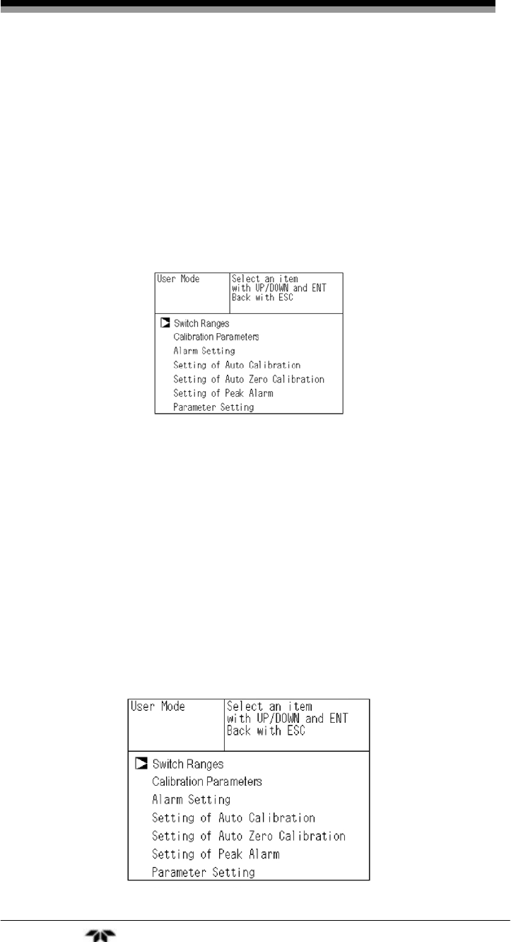
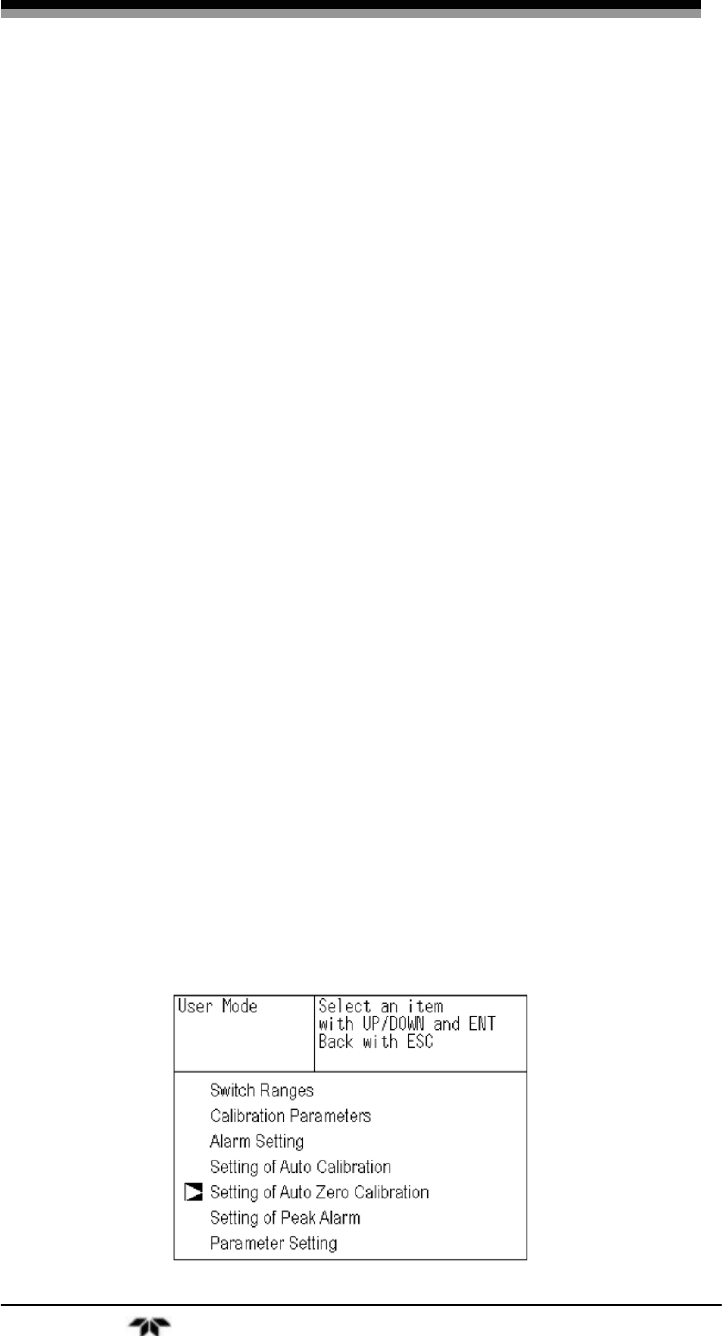
The user mode is where the operator configures the instrument and
sets up various parameters for the intended application. From the user
mode the following menus are available:
• Switch Ranges
• Calibration Parameters
• Alarm Setting
• Setting of Auto Calibration
• Setting of Auto Zero Calibration
• Setting of Peak Alarm
• Parameter Setting
Figure 3-3 shows the overall structure of the Model 7600 display
and menu hierarchy.
3.3 The Display Screen
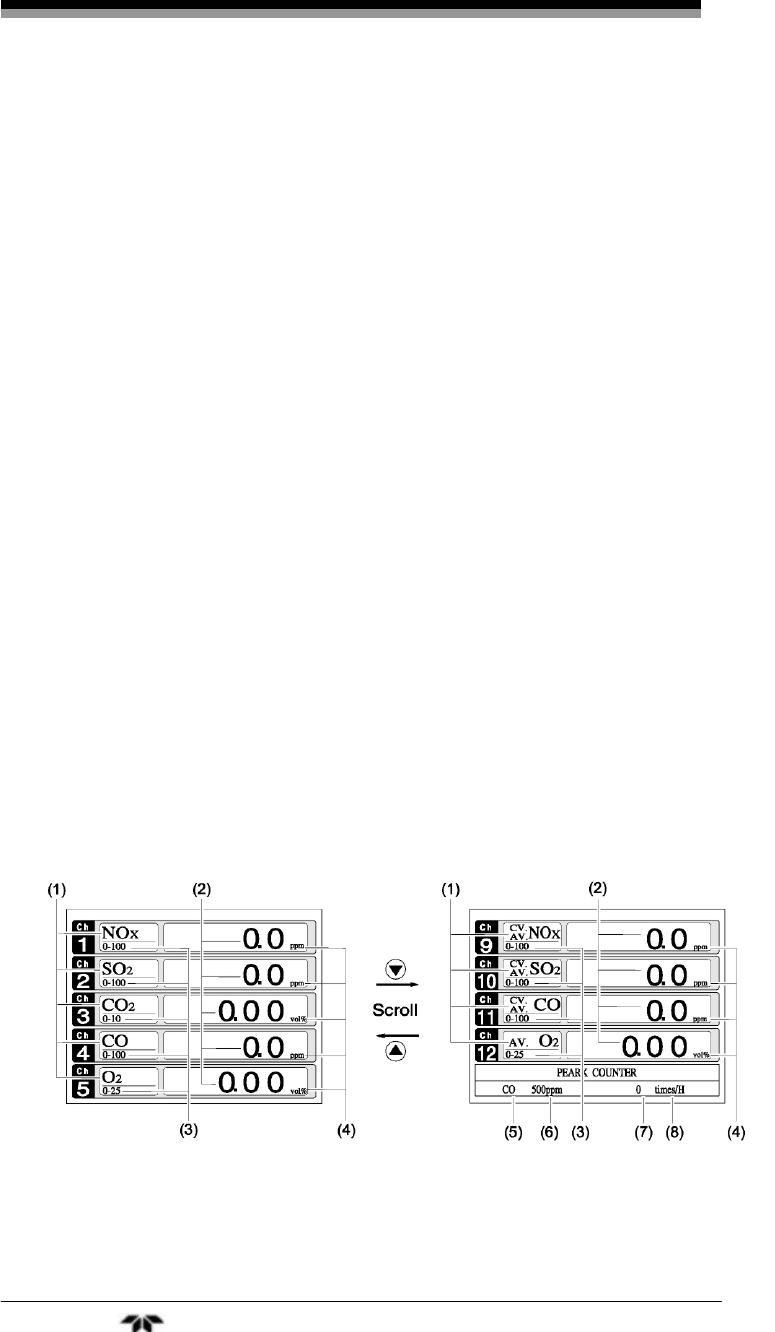
3.3.1 Measurement Mode
The measurement mode screen is the default mode when the power is
turned on. It displays component and concentration information about the
process. The screen depends on the number of components. Figure 3-4 is an
example of a measurement mode screen for an instrument configured for
NO, SO2, CO2, CO and O2 analysis with a 12 channel output.
Figure 3-4: Example Screen—5 Component Analysis 12 Channels
Infrared Gas Analyzer Operation
Teledyne Analytical Instruments 39
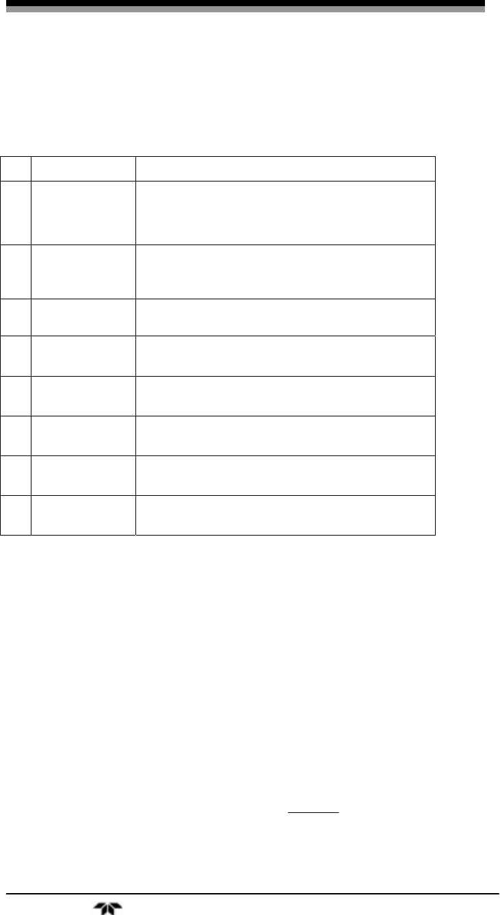
The numbered call outs in Figure 3-4 refer to:
No. Name Function
(1) Component
display Displays component of instantaneous
value, corrected instantaneous value,
corrected average value, etc.
(2) Concentration
display Displays measured value of concentration.
(3) Range display Displays range values.
(4) Unit display Displays unit with ppm and vol %.
(5) Peak alarm
com
p
onent Displays peak alarm component.
(6) Peak alarm
concentration Displays peak alarm concentration display.
(
U
pp
er limit value
)
(7) Peak alarm
times Displays the alarm times exceeding the
p
eak value.
(8) Peak alarm
unit dis
p
la
y
Displays units of peak alarm with times/H.
Instantaneous value and concentration value:
The concentration display of Ch (component) where sampling
components such as “CO2”, “CO” or “O2 are displayed in the component
display, indicates current concentration values of the measured
components contained in gas that is now under measurement.
O2 correction concentration values:
Ch components where “cv**” is displayed as “cv CO” in the
component display are calculated values. They are obtained from the
following equation by setting sampling components, O2 instantaneous/
concentration values and O2 correction reference value (see item 6.8).
Cs
Os21
On-21
output Correction ×
⎟
⎠
⎞
⎜
⎝
⎛
−
=

Operation Model 7600
Teledyne Analytical Instruments 40
Where:
On: The value of the O2 correction reference value (Value set by
application)
Os: Oxygen concentration (%)
Cs: Concentration of relevant measured component. Note that Os
does not exceed the O2 limit value set in “Other Parameter”
See Section 3.6 Maintenance Mode.
The corrected sampling components are NOX, SO2 and CO only.
O2 correction concentration average value:
In the Ch (component) and O2 average value where “CV/AV **” is
displayed as “ AV CO” in the component display, a value obtained by
averaging O2 correction concentration value or O2 average value in a
fixed time is output every 30 seconds.
Averaging time can be changed between 1 minute and 59 minutes
or 1 hour and 4 hours according to the average time settings (See
Section 3.5.7 Parameter Setting).
The set time is displayed as “1h” , for instance, in the range display.
* The measurement ranges of O2 correction concentration value and O2
correction concentration average value are the same as that of the
measuring components. Also, the measurement range of O2 average
value is the same as that of O2.
3.3.2 Setting/Selection Screen
The setting/selection screen is configured as shown in Figure 3-5:
• In the status display area, the current status is displayed.
• In the message display area, messages associated with
operation are displayed.
• In the setting item and selection item display area, items or
values to be set are displayed, as required. To work in a
particular area, move the cursor to any item by using the UP,
DOWN and LEFT/RIGHT keys.

Infrared Gas Analyzer Operation
Teledyne Analytical Instruments 41
Figure 3-5: Setting/Selection Screen Areas
3.4 Basic Operation
Measurement mode
The measurement mode is the default mode of the instrument and
appears when the unit is first turned on. It displays information about the
process being analyzed such as: channel number, component species
analyzed, concentration or calculated value, etc. In this mode, the
display can show up to 5 channels on a single screen. To view additional
channels, scroll down by pressing the DOWN key or back up using the
UP key. Each press scrolls the screen by one channel. You can also
calibrate the instrument from this mode by pressing the appropriate
ZERO or SPAN button. See Section 3.7 Calibration.
User mode displays:
In the user mode you can:
• Switch ranges
• Set calibration parameters
• Adjust alarm settings
Operation Model 7600
Teledyne Analytical Instruments 42
• Set up the Auto Calibration feature
• Setup an auto zero calibration
• Adjust the peak alarm parameter Setting.
These settings are described in Section 3.5.
To enter the user mode from the measurement mode, press the
MODE key. To return to the measurement mode, press the MODE key
again or ESC.
3.5 Setting Up the Analyzer in the User Mode
3.5.1 Switch Ranges
From the Switch Ranges menu you can:
a. Manually select a desired range for any channel.
b. Use the remote range switch contacts to select a range.
c. Select autoranging.
To enter the Switch Ranges menu:
1. Press the MODE key to enter the user mode.
Infrared Gas Analyzer Operation
Teledyne Analytical Instruments 43
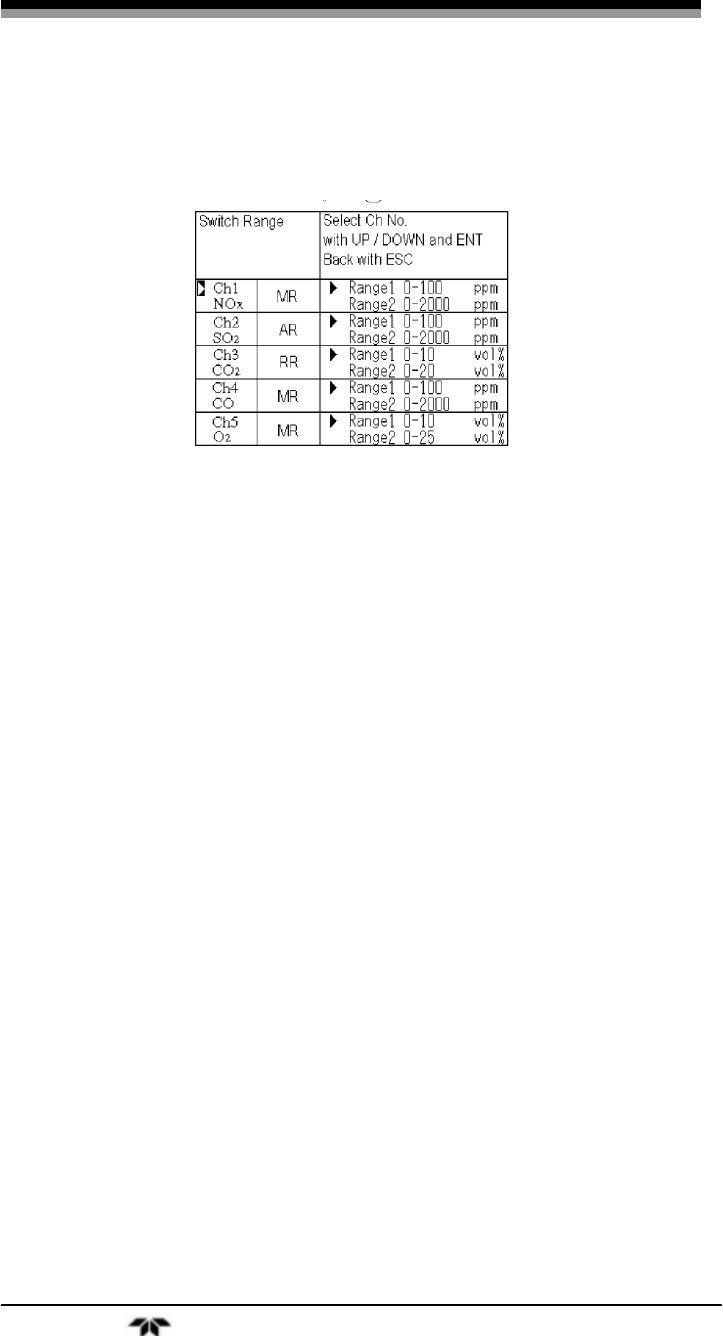
2. Move the cursor to the “Switch Ranges” option and press
ENT. The “Channel Selection” screen appears.
3. Move the cursor by pressing the UP/DOWN keys to the
desired channel and press ENT.
There are 3 range switch modes in the second column to select from:
MR: Manual selection
RR: Remote range switch
AR: Autoranging
The selected range switch mode is highlighted for the channel you
selected.
4. Press the UP/DOWN keys to toggle between the
available switch modes.
5. Then press the ENT key to confirm the selection.
3.5.1.1 MANUAL RANGE SWITCHING
To manually switch between analysis ranges:
1. Select the MR option from the Switch Range screen and
press the ENT key.

Operation Model 7600
Teledyne Analytical Instruments 44
2. Move the highlight of the cursor to range selection and
select the desired range using the UP/DOWN keys. The
highlighted arrow indicates the currently selected range.
3. Press ENT to accept the selection. Measurement is now
carried out using the selected range.
Note: If “RR” or “AR” is selected as range switch mode, manual
range selection as described above is not possible
The range for O2 correction value, O2 correction average
value, and O2 average value is automatically switched if
the corresponding instantaneous value range is switched.
To abort the range selection, press the ESC key and the setting
operation is made invalid and the previous screen appears.
3.5.1.2 RANGE IDENTIFICATION CONTACT OPERATION
In all of the range switch modes (MR, RR, AR), the status of the
range identification relay contact corresponding to each Ch (component)
is closed when Range 1 is selected, and open when Range 2 is selected.
Note that even if the range is switched while a hold of measurement
is in place, for instance, by a remote hold contact input or the hold of
measurement value during calibration, the range identification contact
maintains the contact state immediately before the hold. After stop of the
hold, the contact state of the current range is resumed.

Infrared Gas Analyzer Operation
Teledyne Analytical Instruments 45
3.5.1.3 REMOTE RANGE SELECTION
The range can be selected remotely if a remote switch has been
installed. To use this feature, the range mode must be switched in the
display to RR (Remote Range) .
To configure the instrument for remote range selection:
1. Press the MODE key to enter the user mode.
2. Move the cursor to the “Switch Ranges” option and press
ENT. The “Channel Selection” screen appears.
3. Move the cursor by pressing the UP/DOWN keys to the
desired channel and press ENT.
The selected range switch mode is highlighted for the channel you
selected.
4. Press the UP/DOWN keys to toggle between the
available switch modes until RR is displayed.
5. Press the ENT key to accept the selection.

Operation Model 7600
Teledyne Analytical Instruments 46
3.5.1.4 AUTORANGING
The Model 7600 can be set to autorange where the instrument will
select the analysis range automatically. To use the autorange feature, AR
must be selected for the switch mode. Note that each channel is
independent so that autoranging can be used for some or all of the
available channels. the remaining channels can be configured to manual
or remote switching.
To setup autoranging use the same procedure as Section 3.5.1.1
except you must select AR for the switch mode on the channel or
channels you want to autorange.
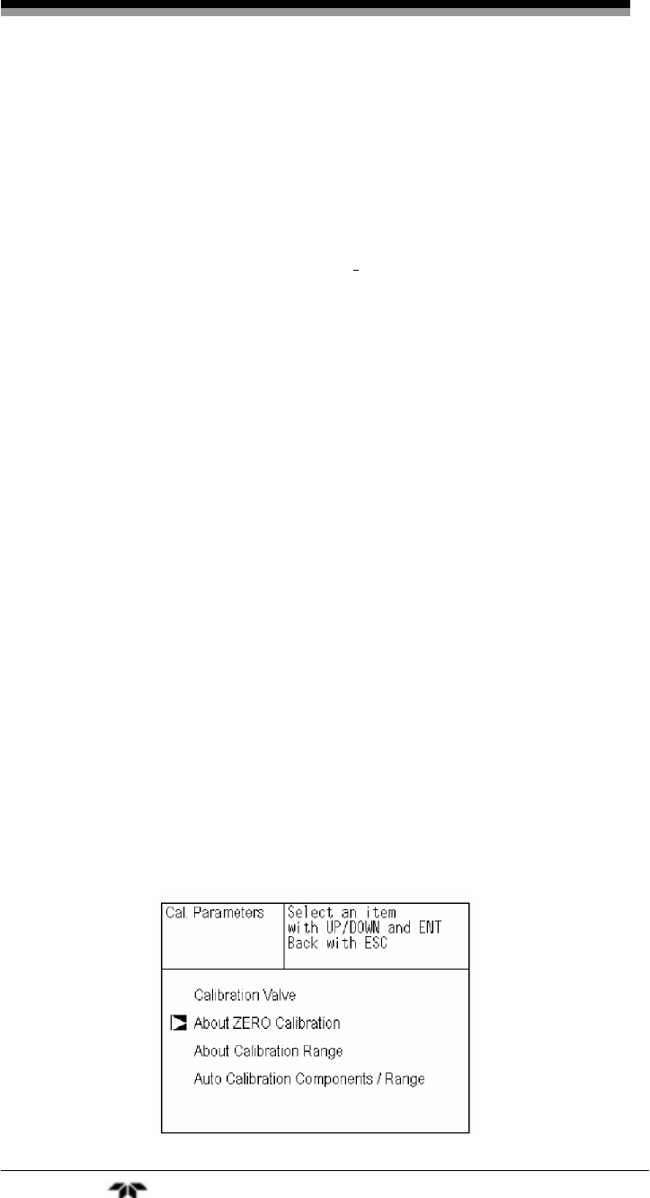
3.5.2 Calibration Parameters
The next menu choice from the user screen is the Calibration
Parameters menu. Here calibration settings can be configured for your
particular application. There are 4 submenus in the Calibration
Parameters menu. They are:
• Calibration Value—set the concentration of calibration gas
• About ZERO Calibration—set each or all components to be
zero calibrated during a manual zero calibration.
• About Calibration Range—sets whether each component
during a zero or span calibration should be calibrated with a
single or dual range.
• Auto Calibration Components/Range— select the component
and range with which auto calibration is to be performed.
3.5.2.1 CALIBRATION VALUE
This submenu allows you to set the concentration of the standard
gas (zero and span) for each channel used for calibration.
To enter the Calibration Value submenu:
1. From measurement mode, press the MODE key to
display the user mode.
2. Point the cursor to “Calibration Parameters” by pressing
the UP or DOWN key.
3. Press the ENT key to enter the Calibration Parameters
menu.
Infrared Gas Analyzer Operation
Teledyne Analytical Instruments 47
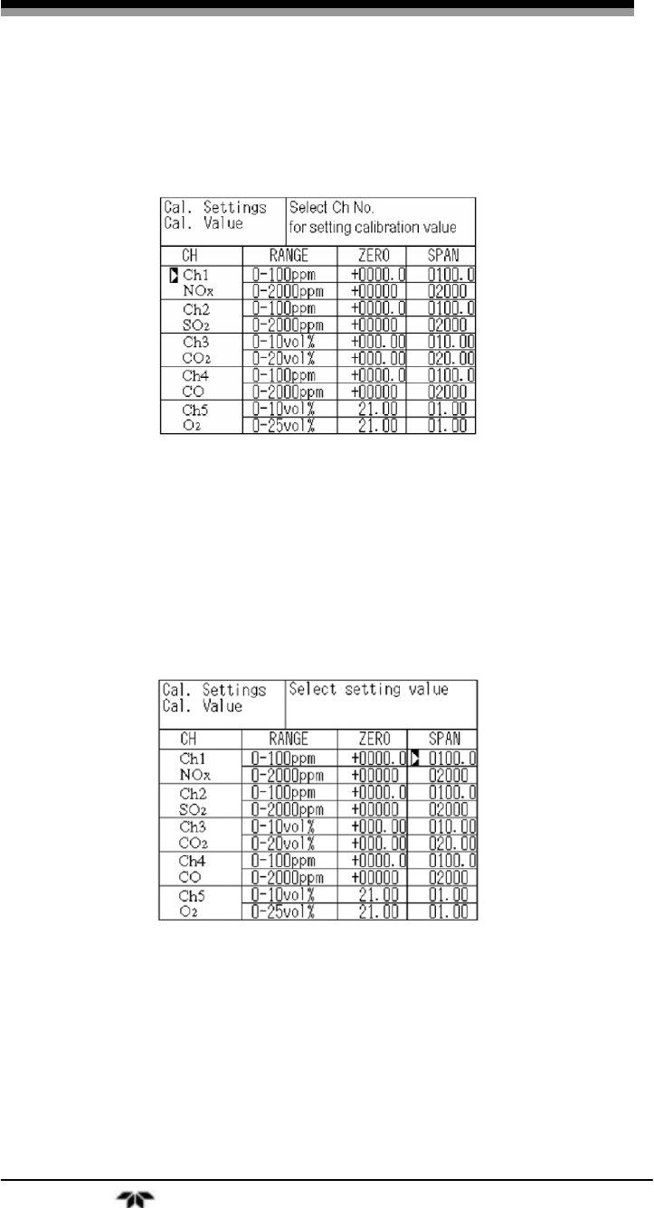
4. In the “Calibration Parameters” screen that appears, point
the cursor to “Calibration Value” by pressing the UP or
DOWN key. Press the ENT key.
To change the concentration of a calibration gas:
1. Point the cursor to the channel you want to set by using
the UP or DOWN key. Press the ENT key.
2. Select the concentration item you want to set by pressing
the UP or DOWN or SIDE key. Press the ENT key, and
the selected value is highlighted.
3. Enter the calibration gas concentration values (zero and
span). For any numerical value entry, press the UP or
DOWN key to increase or decrease a single digit. Select
the next digit by pressing the SIDE key.
4. When the concentration is correct, save the entry by
pressing the ENT key. The saved value becomes valid
from the next calibration process.
Operation Model 7600
Teledyne Analytical Instruments 48
Note: Enter settings that correspond to each range. If a zirconia
type O2 sensor is used, select 21.00 for the field of Zero
(when air is used), and select the concentration listed on
the cylinder if the air contained in a cylinder is used.
To close the calibration concentration value setting process or
cancel this mode midway, press the ESC key. The previous screen will
return.
Setting range of values:
For NOx, SO2, CO2, CO, CH\4, external O2 measurement and built-
in paramagnetic O2 sensors, the setting range for span gas is 1 to 105%
of full scale. The instrument will not accept values outside of this range.
For external Zirconia O2 sensors, the setting range for zero gas is 5
to 25 vol % and span from 0/01 to 5 vol %
3.5.2.2 SETTING OF MANUAL ZERO CALIBRATION
When zero calibration is performed manually, you can choose
whether all components are to be calibrated simultaneously or each
component calibrated while selecting one by one.
This is configured from the About Zero submenu of the Calibration
Parameters menu. To get to the About Zero submenu:
1. From the measurement mode, press the MODE key to
display the user mode.
2. Point the cursor to “Calibration Parameters” by pressing
the UP or DOWN key and press the ENT key.
3. In the “Calibration Parameters” screen that appears, point
the cursor to “About ZERO Calibration” by pressing the
UP or DOWN key. Press the ENT key.

Infrared Gas Analyzer Operation
Teledyne Analytical Instruments 49
This brings up the Cal. Settings ZERO Cal. screen where you can
set whether all components or individually selected components are
zeroed during a manual zero calibration. The choices are:
• at once—these components will be zeroed simultaneously
during a manual zero.
• each—these components will be zeroed individually during a
manual zero.
To change the manual zero setting:
1. In the “Cal. Settings ZERO Cal.” screen, point the cursor
to the channel you want to set by using the UP or DOWN
key. Press the ENT key.
2. Select “at once” or “each” by pressing the UP or DOWN
key to toggle between the two options. Press the ENT
key when the desired option is displayed.
To close the Cal. Settings ZERO Cal. screen or cancel this mode
midway, press the ESC key. The previous screen will return.
Example:
The options “each” or “at once” can be determined for each
channel.
• When the setting is “each”, select the channel on the manual
zero calibration screen (see Section 3.7) and perform a zero
calibration. Only that component is zeroed.
• When the setting is “at once”, performing a manual
calibration (see Section 3.7) will zero calibrate all
components tagged “at once”. You will notice on the manual
Operation Model 7600
Teledyne Analytical Instruments 50
zero calibration screen that all there are cursors on all
components where “at once” is set.
Note: When the cylinder air or atmospheric air is used for the
zero gas, select “at once.”
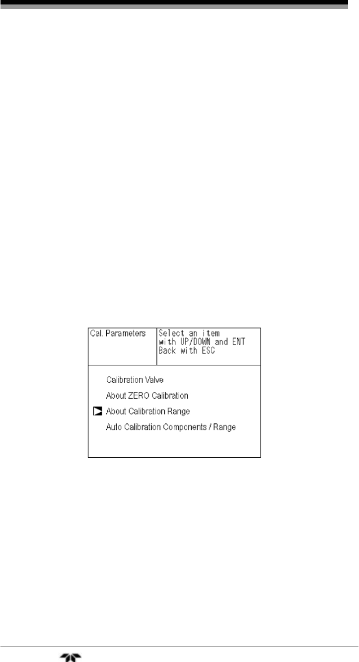
3.5.2.3 SETTING OF CALIBRATION RANGE
Use the “About Calibration Range” submenu to configure the
instrument for calibration on one or two ranges for a channel.
To set calibration one or both ranges:
1. From the measurement mode, press the MODE key to
display the user mode.
2. Point the cursor to “Calibration Parameters” by pressing
the UP or DOWN key and press the ENT key.
3. In the “Calibration Parameters” screen that appears, point
the cursor to “About Calibration Range” by pressing the
UP or DOWN key. Press the ENT key.
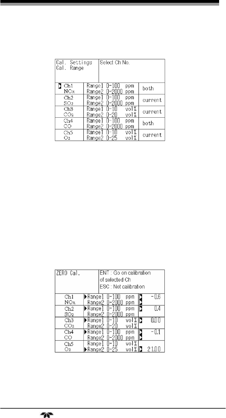
4. In the next screen that appears, point the cursor to the
channel you want to set by pressing the UP or DOWN
key then press the ENT key.
5. On the “calibration range selection” screen that appears,
select “both” or “current” by pressing the UP or DOWN
key.
If “both” is selected, zero or span calibration is performed
with Range 1 and Range 2 of the selected channel.
If “current” is selected, zero or span calibration is
Infrared Gas Analyzer Operation
Teledyne Analytical Instruments 51
performed only for the range displayed when calibration
of the selected channel is performed.
6. Press the ENT key after the selection, and the specified
calibration is set.
To close the calibration range selection screen or cancel this mode
midway, press the ESC key. The previous screen will return.
Note: To perform calibration for “both,” set the same calibration
gas concentration for both ranges.
After setting the calibration range to “both”, you will notice in
the Manual Calibration screen (see Section 3.7), that there are cursors
next to both ranges whereas there would only be a single cursor next to
the range for calibration if “current” was set. For example, if channel 1
and channel 4 were set to “both” then cursors will appear in both ranges
of Ch1 and Ch4 in the Manual Calibration screen shown below.
3.5.2.4 SETTING OF AUTO CALIBRATION COMPONENT/RANGE
This menu is used to select the channel and the range in which auto
calibration is to be performed. If a channel has been set to autoranging

Operation Model 7600
Teledyne Analytical Instruments 52
(AR), it will be calibrated in the range set in this menu when auto
calibration is performed. From this menu you can enable or disable the
auto calibration feature.
To navigate to the Auto Calibration Components/Range menu:
1. From the measurement mode, press the MODE key to
display the user mode.
2. Point the cursor to “Calibration Parameters” by pressing
the UP or DOWN key and press the ENT key.
3. In the “Calibration Parameters” screen that appears, point
the cursor to “Auto Calibration Components/Range” by
pressing the UP or DOWN key. Press the ENT key.
4. In the “Calibration Parameters” screen that appears, point
the cursor to “Auto Calibration Components / Range” by
pressing the UP or DOWN key. Then press the ENT key.
To set the range used for auto calibration:
1. In the “Auto Calibration Components / Range” selection
screen that appears, point the cursor to the channel whose

Infrared Gas Analyzer Operation
Teledyne Analytical Instruments 53
range you want to set using the UP or DOWN key. Then
press the ENT.
2. The cursor next to the range of the selected channel is
highlighted. Select the range to be calibrated using the
UP or DOWN key. Then press the ENT key. The auto
calibration will be performed on the selected range.
Channels which have been set for autoranging (AR) will undergo
the auto calibration and manual calibration on the range selected here.
Once the calibration has started, the range will automatically switch and
on completion of the calibration, the original range is resumed.
The range identification contact is interlocked with the range after
the switch. However if the hold setting is set to “ON” the contact status
before calibration is maintained.
To ENABLE/DISABLE the auto calibration feature:
1. With the cursor next to the range of the selected channel
you want to enable or disable for autocalibration (see
steps 1 and 2 above), use the SIDE key to highlight the
“enable” or “disable” option.
2. Use the UP or DOWN keys to toggle between the two
options then select the desired status by pressing ENT.
To close the Auto Calibration Components/Range screen or cancel
this mode midway, press the ESC key. The previous screen will return.
Note: The order in which the Zero and Span calibrations are
performed in the auto calibration routine are different. For
the zero calibration, the calibration is performed according
to the order in which the channels were set to “enable”. For
Span, the calibration begins with the lowest channel
number first and proceeds sequentially to the highest
channel number set to “enable”.
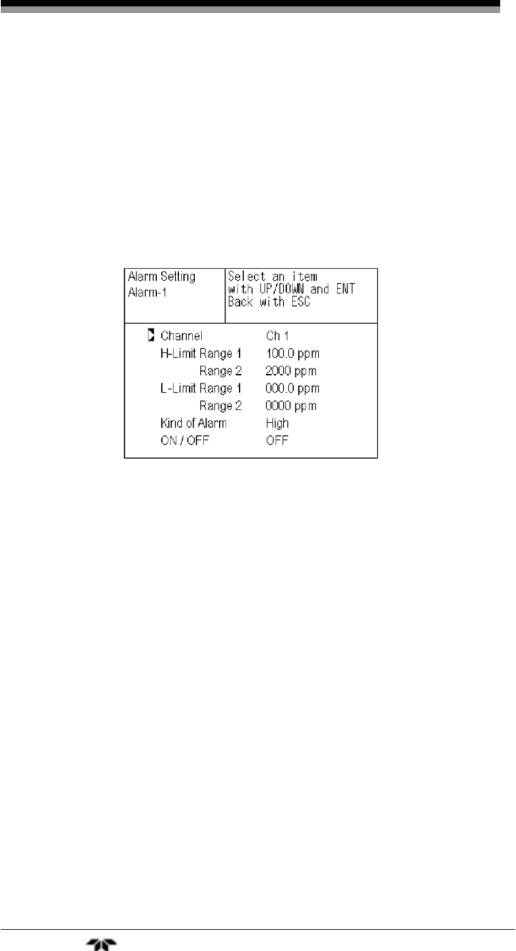
3.5.3 Alarm Setting
The Model 7600 is equipped with 6 alarms (5 or 6 concentration
and a power failure alarm). The alarm configuration and settings can be
assigned to any channel and adjusted at any time by entering the user
mode and navigating to the Alarm Setting submenu. Arbitrary 6 alarm
contact outputs are used which can be configured as:

Operation Model 7600
Teledyne Analytical Instruments 54
• High Limit: sets the upper value (concentration) above which
the alarm will trigger. Has an on-screen display.
• Low Limit: sets a lower value (concentration) below which
the alarm will trigger. Has an on-screen display
• High or Low Limit: triggers an alarm when the concentration
is above the high limit or below the low limit.
• High-High: sets the upper value (concentration) above which
the alarm will trigger.
• Low-Low: sets a lower value (concentration) below which
the alarm will trigger.
• Power Failure: (Alarm 6 only) normally closed contacts open
when power is removed.
Configuring the alarms involves:
• Selecting the alarm type
• Assigning it to a channel
• Establishing setpoints (concentration alarms only)
• Enabling or disabling it
A channel can be configured for multiple alarms.
ON/OFF enables the alarm function if set at ON, or disables the
alarm function if set at OFF. The H-limit value cannot be set below the
L-limit value, and the L-limit value cannot be set above the H-limit
value.
If it is desired to set the H-limit value below the L-limit value
already stored in the memory, reduce the L-limit value beforehand, and
vice versa.
A typical on-screen display for a High alarm is shown below.
When the H-limit alarm occurs, the “H-alarm” message comes on
in the field of relevant channel. Similarly for L-alarm. There is no screen
display for the HH-alarm”, and “LL-alarm” but otherwise, they function
like the H and L limit alarms.

Infrared Gas Analyzer Operation
Teledyne Analytical Instruments 55
CAUTION: ALARMS ARE INACTIVE FOR 10 MINUTES AFTER
TURNING ON POWER.
3.5.3.1 CONFIGURING THE ALARMS
Note: To change an alarm setting, first set the alarm ON/OFF
setting to OFF, and then change the value.
1. From the measurement mode, press the MODE key to
display the user mode.
2. Point the cursor to “Alarm Setting” by pressing the UP or
DOWN key and press the ENT key.
3. In the “Alarm Setting” screen that appears, point the
cursor to the alarm number you want to set (1 through 6)
using the UP or DOWN key. Press the ENT key when the
cursor is on the alarm number you desire.
Operation Model 7600
Teledyne Analytical Instruments 56
4. The alarm item selection screen will appear where you
can select the alarm type, assign it to a channel, define
setpoints, and enable or disable the alarm. Use the UP or
DOWN keys until the cursor is aligned with the desired
function and press the ENT key.
Note: Setpoints are adjustable form 0 to 100% of fullscale
however they must be defined so that H-limit value > L-limit
value and that (H-limit value- L-limit value) > hysteresis.
5. After setting the last feature, store the values by pressing
ENT again.
To close the Alarm Setting screen or cancel this mode midway,
press the ESC key. The previous screen will return.
3.5.3.2 HYSTERESIS SETTING
The hysteresis setting is used prevent chattering of an alarm output
near the alarm setpoint. The hysteresis value range is 0-20% of fullscale
on any analysis range. Figure 3-6 shows the hysteresis width (in %
fullscale) set for a high limit alarm.

Infrared Gas Analyzer Operation
Teledyne Analytical Instruments 57
Figure 3-6: Hysteresis Example for a High Limit Alarm
An alarm output is turned ON if measurement value exceeds the
upper limit value as shown in Figure 3-6. Once the alarm output has
been turned ON, it is not turned OFF until the process value falls below
the hysteresis width.
Note: The hysteresis setting is common to all alarms.
To set the hysteresis value:
1. From the “Alarm No. Selection” screen, point the cursor
to “Hysteresis” by pressing the UP or DOWN key then
press ENT.
2. In the “Hysteresis Value Setting” screen that appears,
enter hysteresis values using the UP or DOWN keys to
increment or decrement a digit. Use the SIDE key to
move to the next digit. When finished, press ENT.

Operation Model 7600
Teledyne Analytical Instruments 58
To close the “Hysteresis Setting” or cancel the mode midway, press
the ESC key. A previous screen will return.
3.5.4 Setting of Auto Calibration
3.5.4.1 AUTO CALIBRATION
Auto calibration is automatically carried out when zero and span
calibrations are set.
In this menu you can set when and how frequent the auto
calibration is performed. You also enable or disable the auto calibration
feature here.
Description of setting items:
Start Time: Setting at the first calibration (day of the week, hour,
minute)
Cycle: A period between the start time of one calibration and
another (unit: hour/day)
Flow Time: The time required for replacement by calibration gas.
Time required for replacement of sample gas after the
calibration is completed (Set by calibration gas.)
ON/OFF: Enable/disable the auto calibration feature.
Note: Before changing the settings of auto calibration, set the
ON/OFF to OFF.
To change the settings:
3. From the measurement mode, press the MODE key to
display the user mode.
4. Point the cursor to “Setting of Auto Calibration” by
pressing the UP or DOWN key and press the ENT key.

Infrared Gas Analyzer Operation
Teledyne Analytical Instruments 59
5. In the “Setting of Auto Calibration” screen that appears,
point the cursor to any item you want to set by pressing
the UP or DOWN key. Press the ENT key.
6. In the “Auto Calibration Parameter Setting” screen that
appears, perform the value entry or the setting. For the
value entry or setting change, use the UP or DOWN key.
To change the setting, use the SIDE key to move the
cursor to the right.
7. After changing the setting, press the ENT key to accept
the change. Auto calibration will now be carried out
using the entered setting value.
To close the “Setting of Auto Calibration” or cancel the mode
midway, press the ESC key. A previous screen will return.
3.5.4.2 GAS FLOW TIME SETTING
In this submenu you select the gas whose flow time is to be
changed. The flow time range is from 60 to 900 seconds. The initial
value is set for 300 seconds.

Operation Model 7600
Teledyne Analytical Instruments 60
To set the flow time:
1. Place the cursor next to “Flow Time,” then press the ENT
key.
2. On the flow time setting screen that appears, use the UP
and DOWN keys to move the cursor to the gas whose
settings you want to change, then press ENT.
3. The highlighted value can be changed. Change the value
by pressing the UP or DOWN key, and then move the
cursor to the right by pressing the SIDE key.
4. After changing the value, press the ENT key.
5. Press the ESC key to return to the automatic calibration
setting screen.
Note: Only the channels used are displayed on this screen. The
Ex. time is the output signal hold extension time after the
completion of calibration. It is valid only when the hold
setting is set to “ON.” The Ex. time set here is also used in
a manual calibration.
The auto calibration contacts are closed during an auto calibration
event.
3.5.4.3 CYCLE SETTING RANGE
The cycle range is settable from 1 to 99 hours or 1 to 40 days. The
initial value is set at 7days.
Note: When an auto calibration starts, the measurement screen
automatically appears.
Infrared Gas Analyzer Operation
Teledyne Analytical Instruments 61
Any operation other than “Stop Auto Calibration” (see
Section 3.5.4.5) is not permitted during auto calibration.
“Stop Auto Calibration” cannot be performed when the key
lock is ON.
To cancel auto calibration, set the key lock to OFF and
then execute “Stop Auto Calibration”.
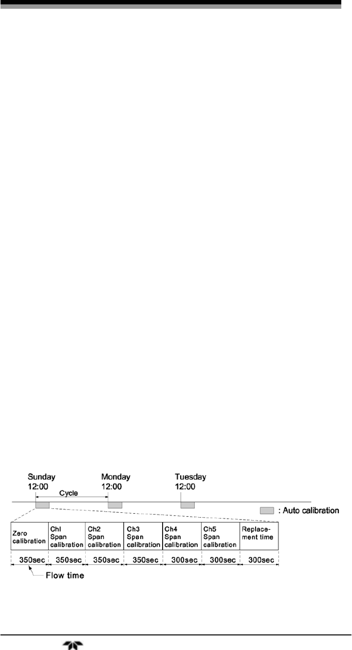
Auto Calibration Example
Start Time SUN 12:00
Cycle 1 day
Flow Time Zero 350 sec
Ch1 Span 350 sec
Ch1 Span 350 sec
Ch1 Span 350 sec
Ch1 Span 300 sec
Ch1 Span 300 sec
EX. time 300 sec
ON/OFF ON
Figure 3-7 shows the auto calibration with the above settings.
Figure 3-7: Example Auto Calibration
Operation Model 7600
Teledyne Analytical Instruments 62
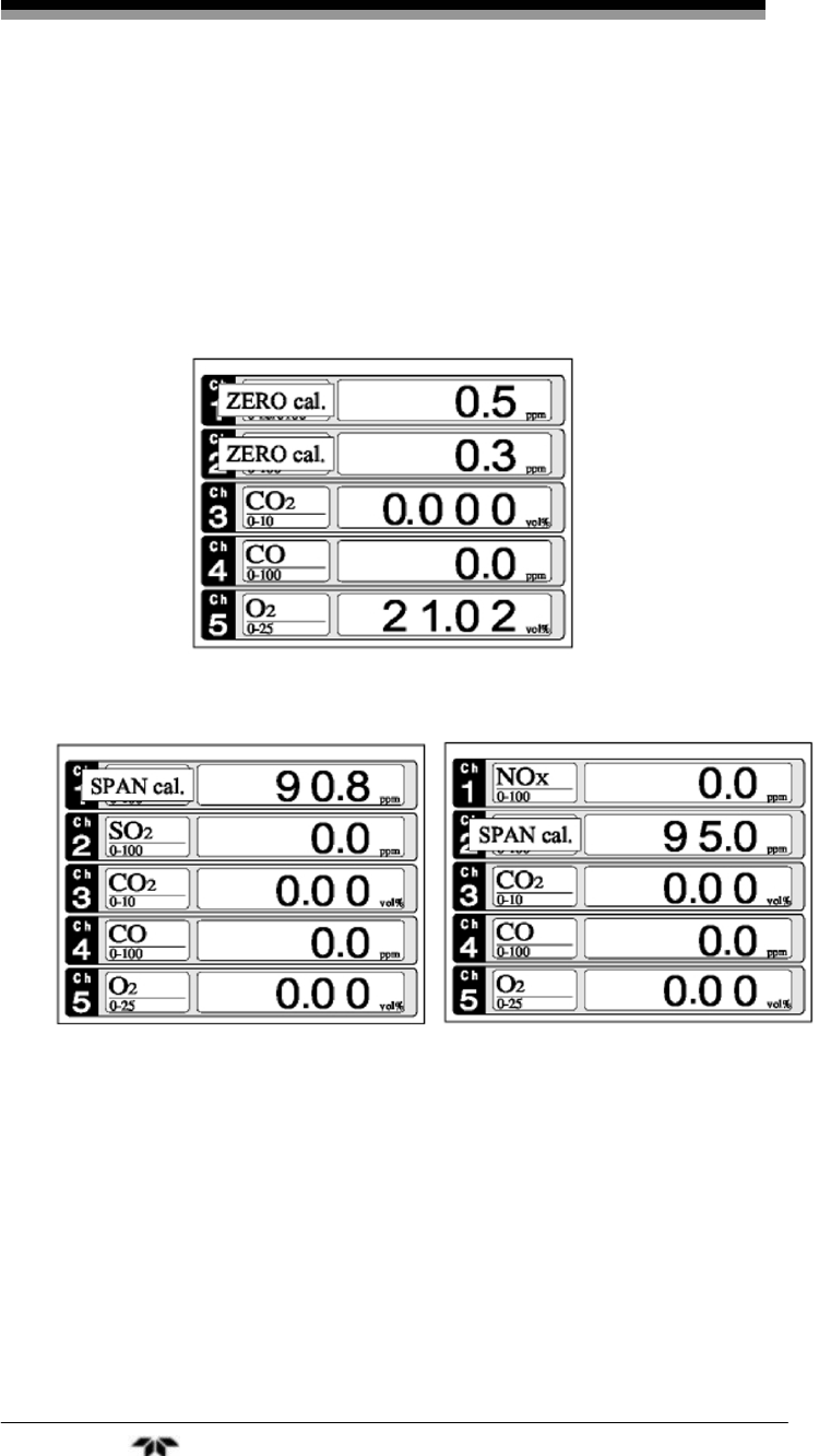
When a channel enabled for auto calibration is in the calibration
mode, a message indicating ZERO cal. or SPAN cal. will appear on the
measurement screen. For example, if channels 1 and 2 have the auto
calibration setting enabled, when the calibration event takes place, both
channels 1 and 2 will indicate ZERO cal. when the zero calibration is
being performed. Zero calibrations are performed first and all enabled
channels will zero simultaneously.
When the zero calibrations are finished, channel 1 will enter the
span calibration followed by channel 2.
3.5.4.4 REMOTE START
An auto calibration is always available by keeping the remote start
input closed for at least 1.5 seconds. The remote start can initiate an auto
calibration whether the parameter setting is ON or OFF.
3.5.4.5 FORCED RUN/STOP OF AUTO CALIBRATION
Auto calibration can be performed manually or forcibly stopped
while the calibration is performed.
Infrared Gas Analyzer Operation
Teledyne Analytical Instruments 63
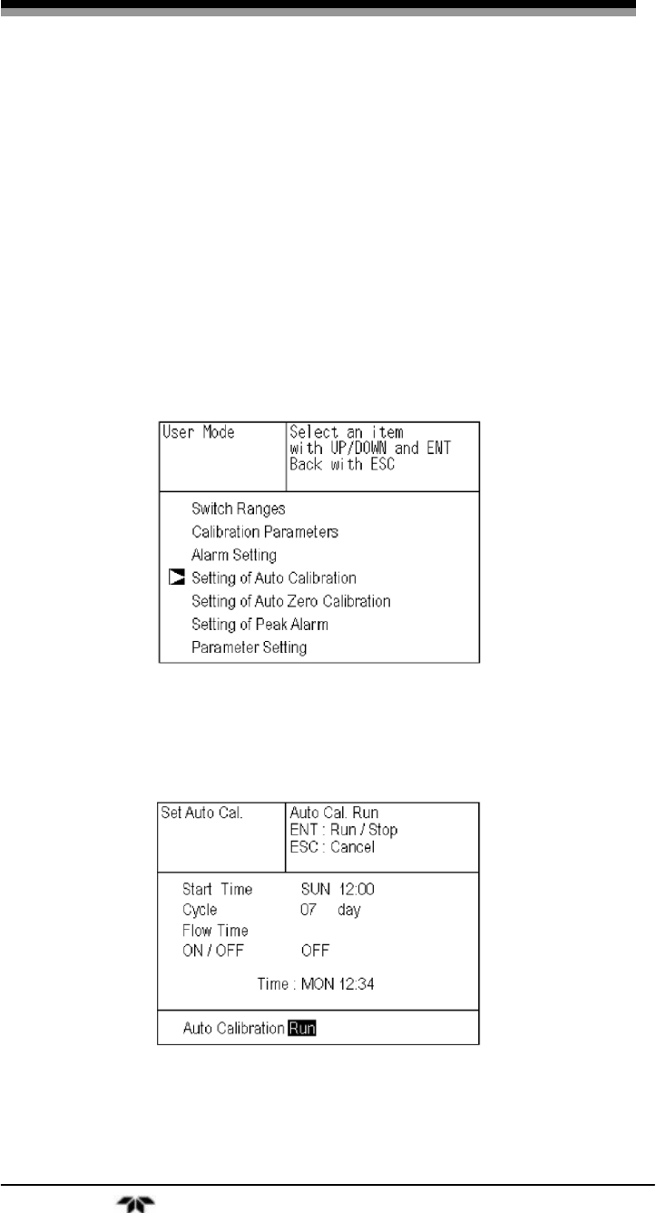
3.5.4.5.1 MANUAL EXECUTION OF AUTO CALIBRATION
To perform the auto calibration cycle manually:
1. From the measurement mode, press the MODE key to
display the user mode.
2. Point the cursor to “Setting of Auto Calibration” by
pressing the UP or DOWN key and press the ENT key.
3. In the “Setting of Auto Calibration” item selection screen
that appears, point the cursor to “Auto Calibration Run”
by pressing the UP or DOWN keys. Press the ENT
key.
4. “Run” is highlighted, displaying a message to confirm the
execution of auto calibration. Press the ENT key to
execute the auto calibration, or press the ESC key to
cancel.
3.5.4.5.2 FORCIBLY END AN AUTO CALIBRATION
To abort an auto calibration event:
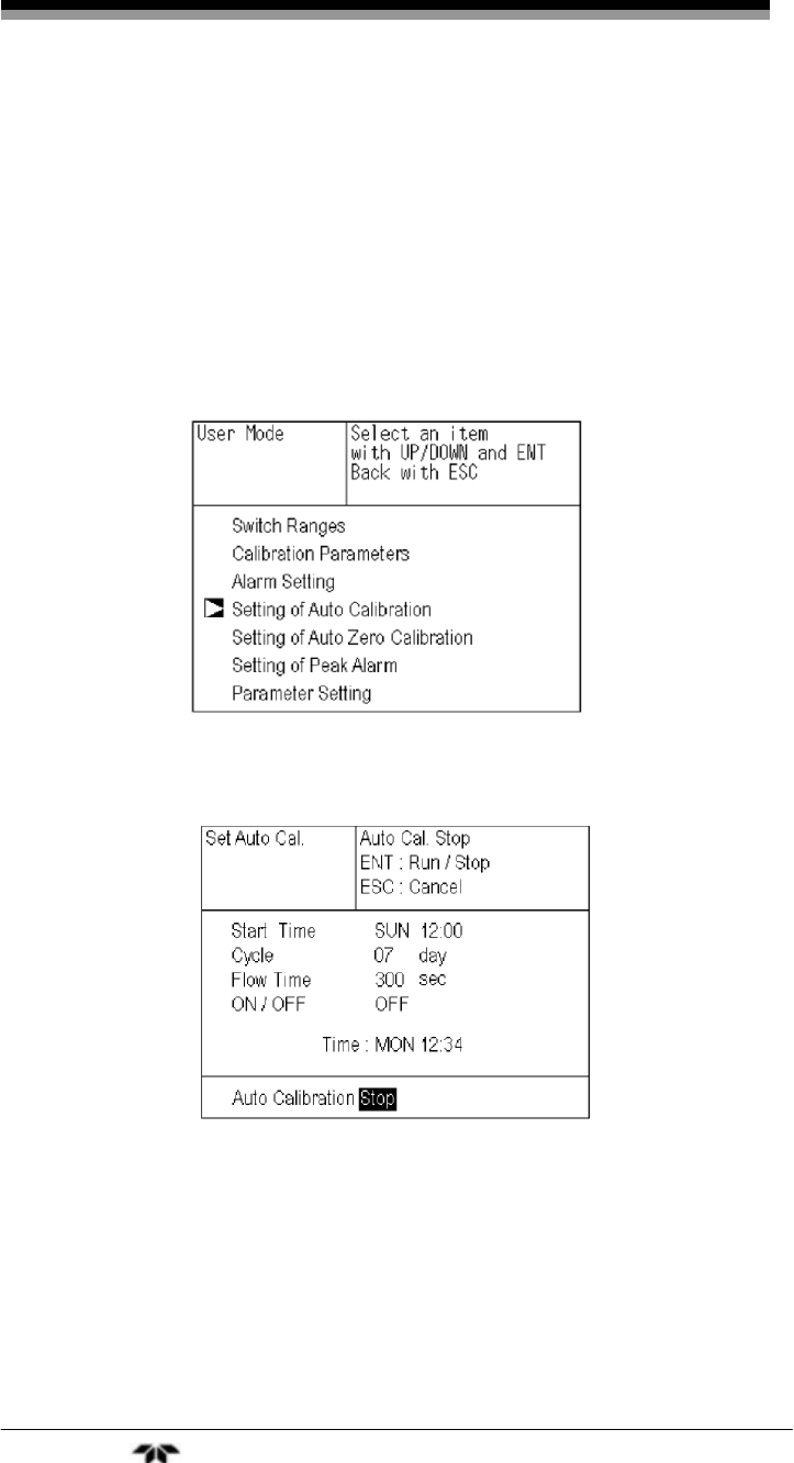
Operation Model 7600
Teledyne Analytical Instruments 64
5. From the measurement mode, press the MODE key to
display the user mode.
6. Point the cursor to “Setting of Auto Calibration” by
pressing the UP or DOWN key and press the ENT key.
7. In the “Setting of Auto Calibration” item selection screen
that appears, point the cursor to “Auto Calibration Run”
by pressing the UP or DOWN keys. Press the ENT
key.
8. “Stop” is highlighted, displaying a message to confirm
the stop of auto calibration. Press the ENT key to stop the
auto calibration, or press the ESC key to cancel the abort.
Note: During auto calibration, the keys are inoperable other than
key lock ON/OFF and “Stop Auto Calibration.”
When the key lock is set to ON, even the “Auto Calibration
Stop” is locked out. To stop “Auto Calibration” forcedly, set
the key lock to OFF and then execute “Auto Calibration
Stop” as detailed above.
Infrared Gas Analyzer Operation
Teledyne Analytical Instruments 65
3.5.5 Setting of Auto Zero Calibration
3.5.5.1 AUTO ZERO CALIBRATION
Auto zero calibration is automatically carried out when the zero
calibration is set. Components for which a calibration is to be made are
determined by setting of auto calibration component in Section 3.5.3.
Similar to the menu choices and operation of the auto calibration, in
this menu you can set when and how frequent the auto zero calibration is
performed. You also enable or disable the auto zero calibration feature
here.
Description of setting items:
Start Time: Setting at the first calibration (day of the week, hour,
minute)
Cycle: A period between the start time of one calibration and
another (unit: hour/day)
Flow Time: The time required for replacement by calibration gas.
Time required for replacement of sample gas after the
calibration is completed (Set by calibration gas.)
ON/OFF: Enable/disable the auto calibration feature.
Note: Before changing the settings of auto calibration, set the
ON/OFF to OFF.
To change the settings:
1. From the measurement mode, press the MODE key to
display the user mode.
2. Point the cursor to “Setting of Auto Zero Calibration” by
pressing the UP or DOWN key and press the ENT key.

Operation Model 7600
Teledyne Analytical Instruments 66
3. In the “Setting of Auto Zero Calibration” screen that
appears, point the cursor to any item you want to set by
pressing the UP or DOWN key. Press the ENT key.
4. In the “Auto Zero Calibration Parameter Setting” screen
that appears, perform the value entry or the setting. For
the value entry or setting change, use the UP or DOWN
key. To change the setting, use the SIDE key to move the
cursor to the right.
5. After changing the setting, press the ENT key to accept
the change. Auto zero calibration will now be carried out
using the entered setting value.
To close the “Setting of Auto Calibration” or cancel the mode
midway, press the ESC key. A previous screen will return.
The contacts for the auto zero calibration are closed during auto
zero calibration.
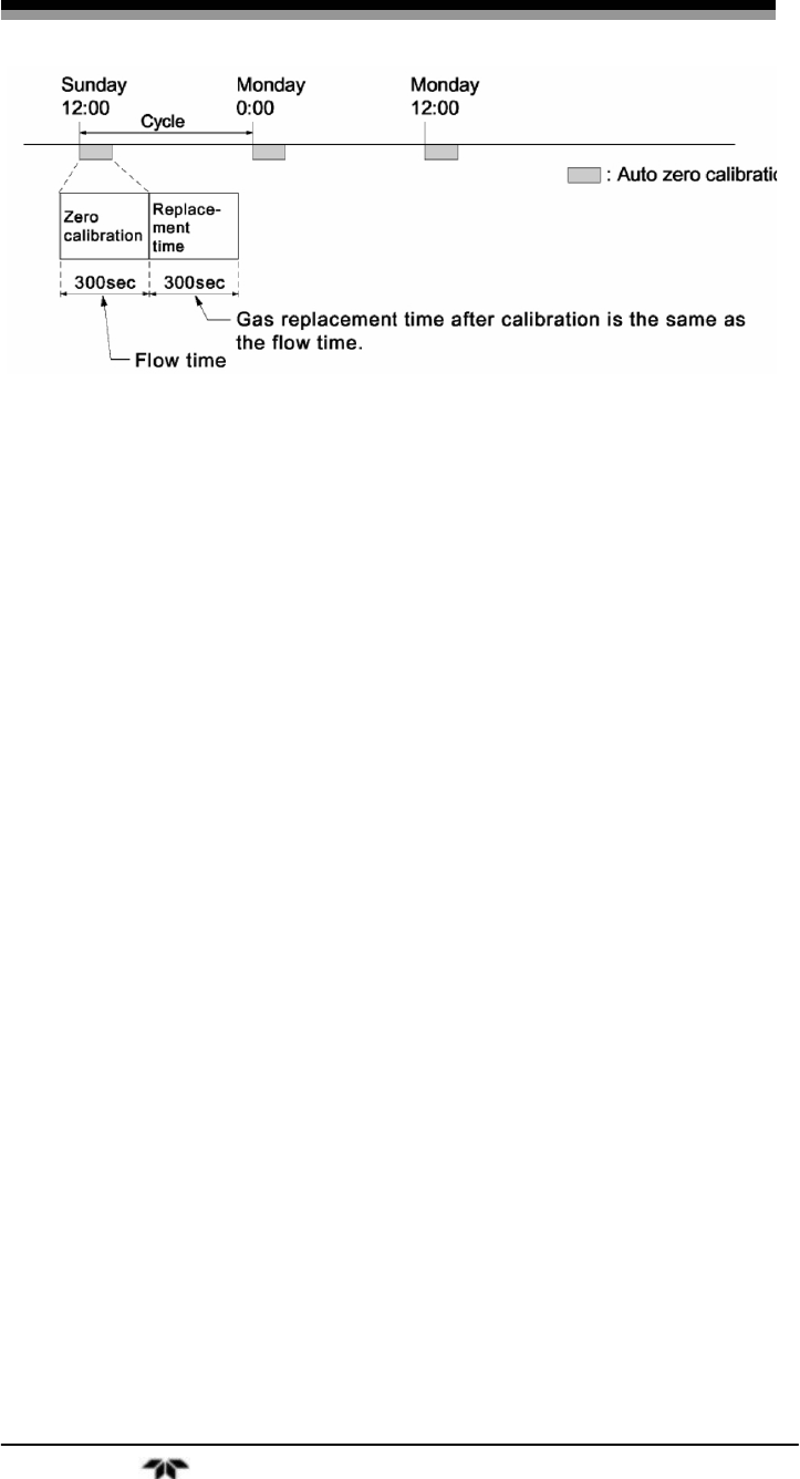
Auto Zero Calibration Example
Start Time SUN 12:00
Cycle 12 hour
Flow Time 300 sec
ON/OFF ON
Figure 3-8 shows the auto zero calibration with the above settings.
Infrared Gas Analyzer Operation
Teledyne Analytical Instruments 67
Figure 3-8: Example Auto Zero Calibration
Note: When an auto zero calibration starts, the measurement
screen automatically appears.
Any operation other than “Stop Auto Zero Calibration” (see
Section 3.5.4.5 is not permitted during auto calibration.
“Stop Auto Zero Calibration” cannot be performed when
the key lock is ON.
To cancel auto zero calibration, set the key lock to OFF
and then execute “Stop Auto zero Calibration”. 0 If the auto
calibration period and auto zero calibration period have
overlapped, the auto calibration is retained, ignoring the
auto zero calibration of that period.
If the auto calibration and the auto zero calibration periods
overlap, the auto calibration setting is retained. The
instrument ignores the auto zero calibration period.
When the hold setting is set to ON, the hold time of auto
calibration contact and measurement value output signal is
extended after calibration for gas replacement time.
Turn on the power again after it is turned off (including the
case of power failure) at the time set as the next start time
in auto zero calibration, and then repeat it in the set cycle.

Operation Model 7600
Teledyne Analytical Instruments 68
3.5.5.2 FORCED RUN/STOP OF AUTO ZERO CALIBRATION
Like the auto calibration, the auto zero calibration can be
performed manually or forcibly stopped while the calibration is
performed.
3.5.5.2.1 MANUAL EXECUTION OF AUTO ZERO CALIBRATION
To perform the auto calibration cycle manually:
1. From the measurement mode, press the MODE key to
display the user mode.
2. Point the cursor to “Setting of Auto Zero Calibration” by
pressing the UP or DOWN key and press the ENT key.
3. In the “Setting of Auto Zero Calibration” item selection
screen that appears, point the cursor to “Auto zero
Calibration Run” by pressing the UP or DOWN keys.
Press the ENT key.
4. “Run” is highlighted, displaying a message to confirm the
execution of auto calibration. Press the ENT key to
execute the auto calibration, or press the ESC key to
cancel.
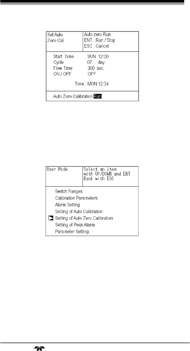
Infrared Gas Analyzer Operation
Teledyne Analytical Instruments 69
3.5.5.2.2 FORCIBLY END AN AUTO ZERO CALIBRATION
To abort an auto zero calibration event:
1. From the measurement mode, press the MODE key to
display the user mode.
2. Point the cursor to “Setting of Auto Calibration” by
pressing the UP or DOWN key and press the ENT key.
3. In the “Setting of Auto Calibration” item selection screen
that appears, point the cursor to “Auto Calibration Run”
by pressing the UP or DOWN keys. Press the ENT
key.
4. “Stop” is highlighted, displaying a message to confirm
the stop of auto calibration. Press the ENT key to stop the
auto calibration, or press the ESC key to cancel the abort.
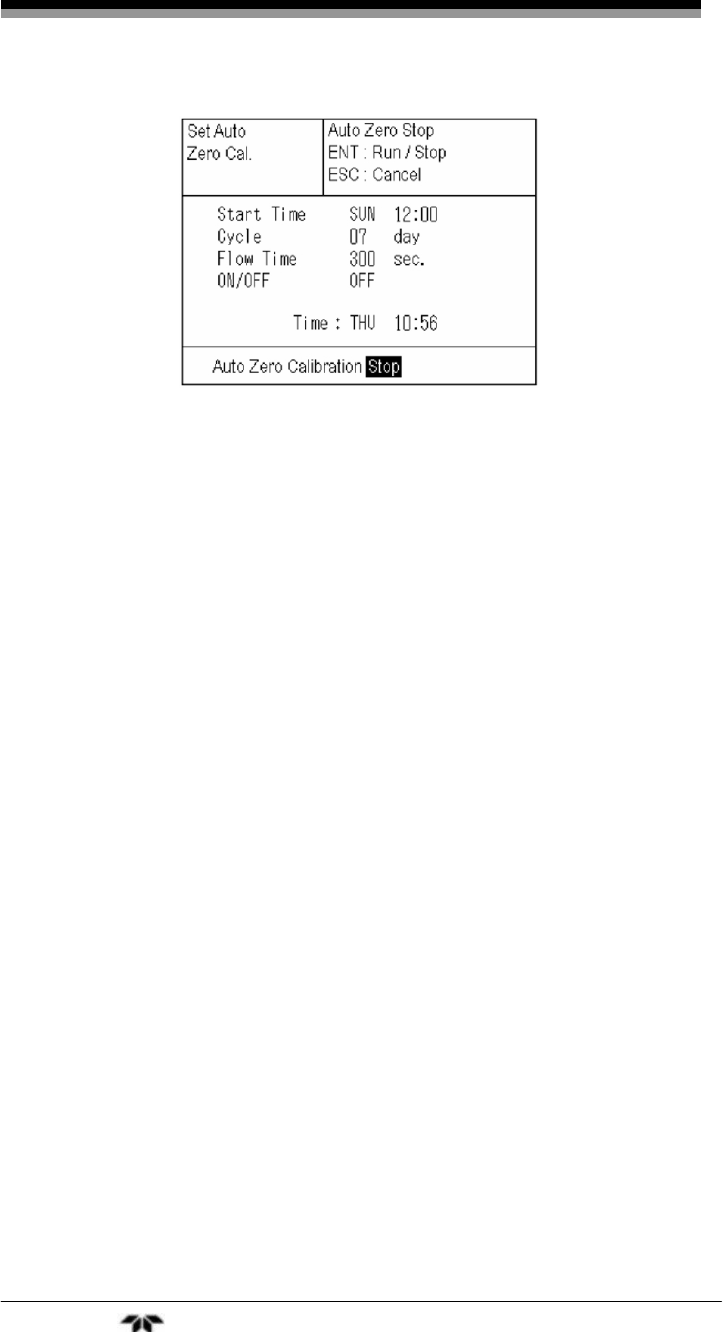
Operation Model 7600
Teledyne Analytical Instruments 70
Note: During auto zero calibration, the keys are inoperable other
than key lock ON/OFF and “Stop Auto Zero Calibration.”
When the key lock is set to ON, even the “Auto Zero
Calibration Stop” is locked out. To stop “Auto Zero
Calibration” forcedly, set the key lock to OFF and then
execute “Auto Zero Calibration Stop” as detailed above.
3.5.6 Peak Alarm Setting
The optional peak alarm is triggered whenever the CO
concentration exceeds the upper limit value for a preset number of times.
The peak number is set from within the Peak Alarm Setting menu.
Note: Only instruments with the peak alarm option installed will
have this menu.
The following items are set within the peak alarm menu:
• OFF/ON status of peak alarm
• Alarm setpoint value
• Alarm count (number of peaks)
• Hysteresis
To adjust the peak alarm settings:
1. From the measurement mode, enter the user mode by
pressing the MODE key.
2. Point the cursor to “Setting of Peak Alarm” by pressing
the UP or DOWN key.
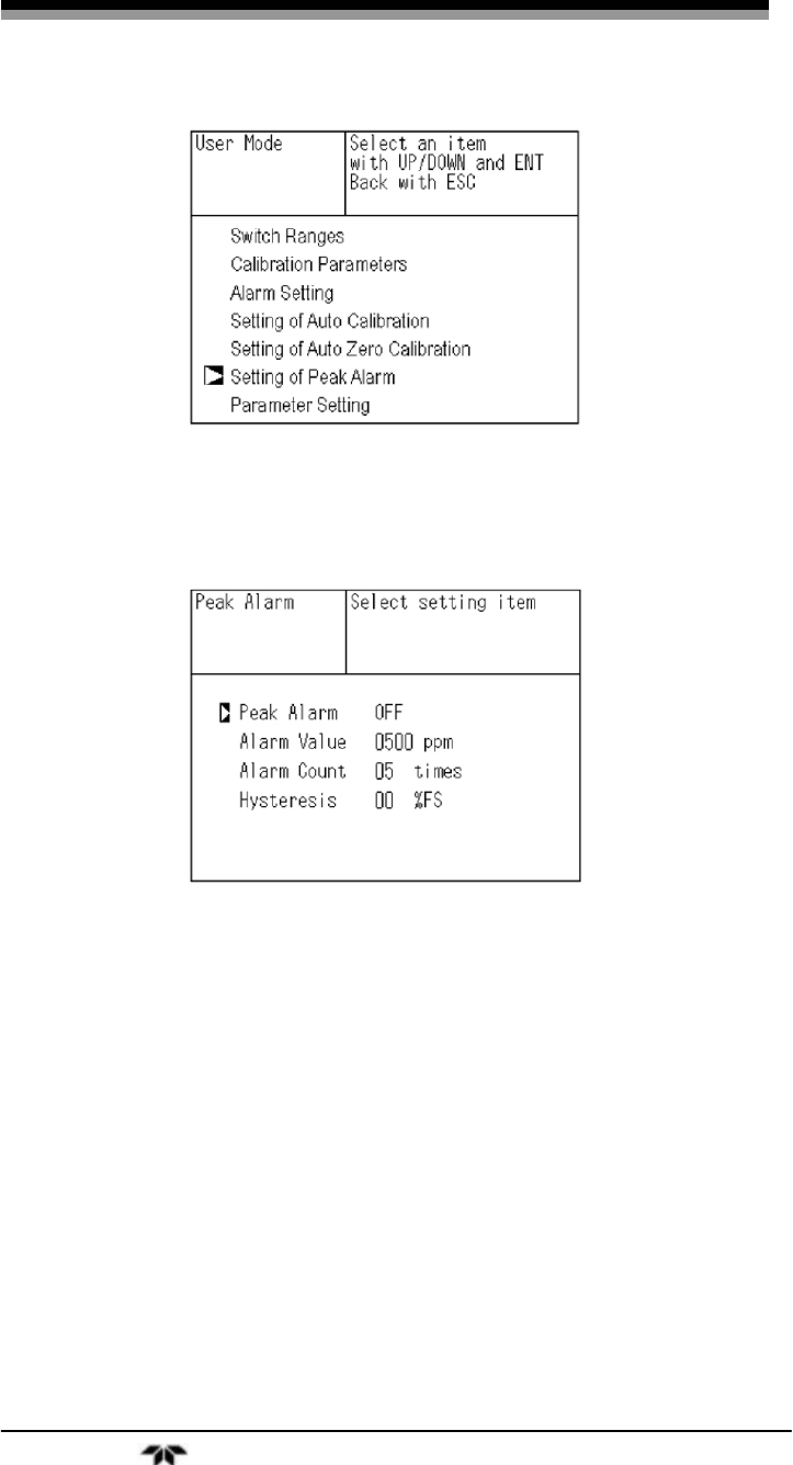
Infrared Gas Analyzer Operation
Teledyne Analytical Instruments 71
3. Press the ENT key.
4. In the “Peak Alarm Setting” item selection screen that
appears, point the cursor to any item you want to set by
pressing the UP or DOWN key. Then press the ENT key.
5. Enter numeric values by using the UP or DOWN keys.
Use the SIDE key to move the cursor to the right. Press
the ENT key to save the change.
To close the “Peak Alarm Setting” or cancel the mode midway,
press the ESC key. A previous screen will return.
Description of setting items:
Peak Alarm: ON/OFF of peak alarm
Alarm Value: If measuring value exceeds the set alarm value in
ppm, a peak counter increments by 1.
Alarm Count: When a peak in excess of the alarm value occurs,
a peak count is incremented. The alarm count is
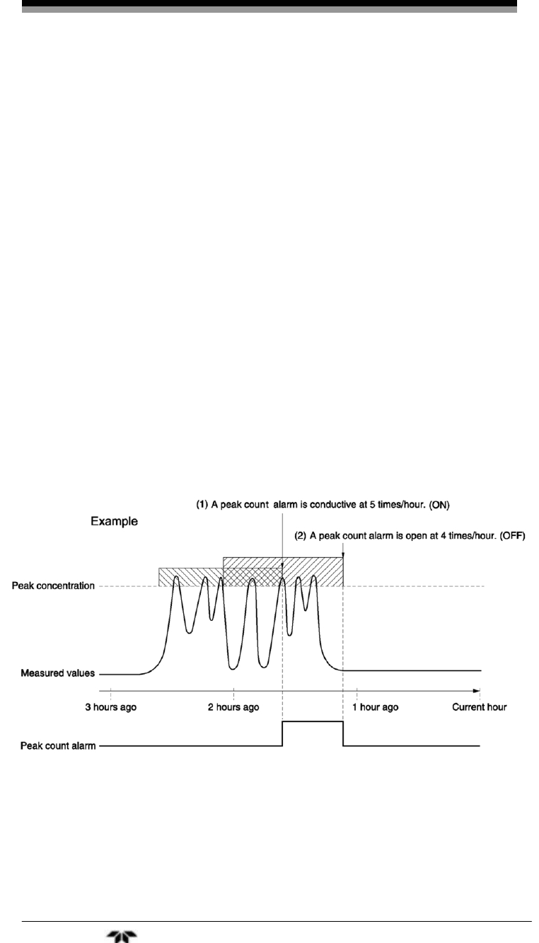
Operation Model 7600
Teledyne Analytical Instruments 72
the numerical value which upon reaching will
trigger the peak alarm.
Hysteresis: To prevent possible chattering when the
measuring value may exceed the set peak
concentration by only 1 time, the peak count has
an allowance in the hysteresis width.
Setting range:
Alarm value: 10 to 1000 ppm, 5 ppm step (initial value: 500
ppm)
Alarm count: 1 to 99 times (initial value: 5 times)
Hysteresis: 0 to 20 % of full scale (initial value: 0% of full
scale).
Action of peak alarm:
If CO concentration exceeds the alarm value, counting will begin.
If the number of peaks is over the set times per hour, the peak alarm
contact closes (ON). If it is less than the set times per hour, it is open
(OFF).
Figure 3-9: Peak Alarm Example
Figure 3-9 depicts the behavior of the Peak alarm where the alarm
count has been set to 5. At the point labeled (1), the peak count alarm is
turned ON since the alarm count has reached the threshold of 5 per hour.
Since peaks of more than 5 times within an hour occur between the
Infrared Gas Analyzer Operation
Teledyne Analytical Instruments 73
interval (1) and (2), the peak count alarm remains ON. At (2), the peak
count has fallen to 4 per hour so the peak alarm is turned OFF.
Like the hysteresis of the alarm setting , the hysteresis prevents
possible chattering when measured gas is fluctuated near the alarm
value.
CAUTION: FOR 10 MINUTES AFTER THE POWER IS TURNED
ON, A PEAK ALARM COUNTING IS NOT
PERFORMED.
Releasing peak count alarm:
To release the peak count alarm, set the peak alarm to OFF.
Turning the peak alarm back ON again resets the count to 0.
3.5.7 Parameter Setting
This menu allows you to adjust parameter settings such as:
• Time
• Key lock
• Output hold
• Reset average output
• Response time
• Average period
• Backlight timer
• Enter maintenance mode
Description of setting items:
Current Time: Current year, month, date, day of the week, hour, and
minute setting in this order.
Note: The clock backup time is 2 days. If power is off for 2 days or
longer, the time setting will need to be set again.
Key Lock: Sets with ON/OFF. When set to ON, all key
operations except key lock OFF are disabled.
Output Hold: Sets whether calibration output is held or not, and
the holding value setting.

Operation Model 7600
Teledyne Analytical Instruments 74
Reset Av. Output: Resets the average value.
Response time: Sets the response time of the electrical system.
Average Period: Sets the moving average time.
Backlight Timer: Sets an automatic OFF of the backlight of display
unit and the time until the backlight is turned OFF.
Maintenance mode: Enters passwords to switch to the Maintenance
mode.
For the maintenance mode, see Section 3.6.
To make parameter changes:
1. From the measurement mode, enter the user mode by
pressing the MODE key.
2. Point the cursor to “Parameter Setting” by pressing the
UP and DOWN keys. Then press ENT.
3. In the “Parameter Setting” screen that appears, point the
cursor to any item you want to set by pressing the UP or
DOWN key. Then Press ENT.
4. Enter numeric values by using the UP or DOWN keys.
Use the SIDE key to move the cursor to the right. After
setting, press the ENT key to save the parameter setting.
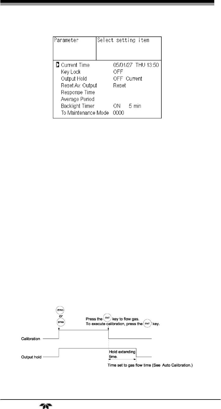
Infrared Gas Analyzer Operation
Teledyne Analytical Instruments 75
To close the “Setting of Auto Calibration” or cancel the mode
midway, press the ESC key. A previous screen will return.
Settings range:
Hold setting: 0 to 100% FS
Response time: 1 to 60 sec. (Initial value: 15 sec)
Average period: 1 to 59 min or 1 to 4 hours (Initial value: 1 hour)
Backlight Timer: 1 to 60 min (Initial value: OFF)
Maintenance mode: 0000 to 9999 (Initial value: 0000)
3.5.7.1 OUTPUT HOLD
By setting an output hold to ON, the output signal of each channel is
held during the calibration (manual calibration and auto calibration) plus
the gas flow time as shown in Figures 3-10 through 3-12. Refer to Section
3.5.4, Setting of Auto Calibration for a description of the gas flow time.
Regardless of Hold ON/OFF setting, an output signal can always be held
via an external input.
Manual calibration
Figure 3-10: Output Hold for Manual Calibration

Operation Model 7600
Teledyne Analytical Instruments 76
Auto calibration
Figure 3-11: Output Hold for Auto Calibration
External hold
Figure 3-12: Output Hold for External Hold
Screen display during hold
For Auto calibration and external holds, the “on Hold” message
will be shown blinking on the measurement screen.
In a manual calibration, the screen displays the process of
calibration so the “on Hold” message is not displayed even if the output
signal is held. However, “on Hold” message is displayed during the hold
extending time shown in Figure 3-10.
For both manual and auto calibration, if the calibration is cancelled
after the calibration gas has been directed to the analyzer, the hold
extending time will be performed.
There are two types of hold values that you can use: “current” or
“setting”. Current uses the existing value immediately before entering
output hold, while “setting” uses an arbitrary value that you set before
initiating the hold.
To change or set the value for a hold:

Infrared Gas Analyzer Operation
Teledyne Analytical Instruments 77
1. From the measurement screen, press the MODE key to
enter the user mode then navigate to the Parameter
Setting option. Press the ENT key to bring up the
parameter setting screen.
2. Select the Output Hold option by moving the cursor to it
using the UP and Down keys. Select it by pressing ENT.
3. “ON” or “OFF” is highlighted. If you desire to change
the state, press the UP or DOWN key to toggle between
ON and OFF. Press the ENT key to select the desired
state.
4. To change the hold value, use the SIDE key to highlight
“Current” or “Setting”. Select “Setting” by pressing the
UP or DOWN key until that option appears then press
ENT. The screen changes to the hold setting screen where
you can select the channel and hold value for that
channel.
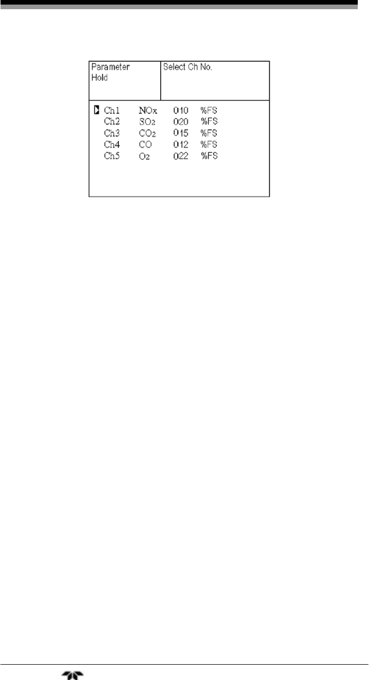
Operation Model 7600
Teledyne Analytical Instruments 78
5. On the parameter hold screen that appears, move the
cursor next to the channel you want to make the setting
by pressing the UP or DOWN key, and then press ENT.
6. The value is highlighted, indicating that the value can be
changed. Change the numerical value by pressing the
UP or DOWN key, and then move the cursor to the
right by pressing the SIDE key.
7. After the value is changed, press the ENT key to save.
8. Press the ESC key to return to the parameter setting
screen.
The setting is expressed in % against the range for both ranges. For
example, when 0 to 1000 ppm is selected as the range, and 10% FS is
selected as hold setting, the output equivalent of 100 ppm is output and
held irrespective of the measurement value at that time.
Description of setting:
Instantaneous value display of the measurement cannot be held.
Only the output can be held.
If set value is selected for hold, instantaneous O2 correction value is
calculated and held based on the set value.
Range identification contact output cannot be switched even if the
range is switched during the hold.
3.5.7.2 AVERAGE VALUE RESET:
This mode is used to clear all average values O2 correction average
and O2 average, and restarts averaging. All average values are reset at
the same time. The indication value and output value is 0 ppm, vol %
etc. at the time of the reset input (Refer to the average period). To

Infrared Gas Analyzer Operation
Teledyne Analytical Instruments 79
perform a reset, the contacts must close for at least 1.5 seconds. See
Figure 3-13. Resetting occurs as the contacts reopen.
Figure 3-13: Average Value Reset
3.5.7.3 RESPONSE TIME
The response time of the electrical system can be changed.
Individual settings are available for each component.
Note: Response time does not provide exact seconds for the
setting time, but rather it is a guide to the overall response.
3.5.7.4 AVERAGE PERIOD
This submenu allows you to set an averaging period over which the
average value of O2 correction and O2 average are sampled.
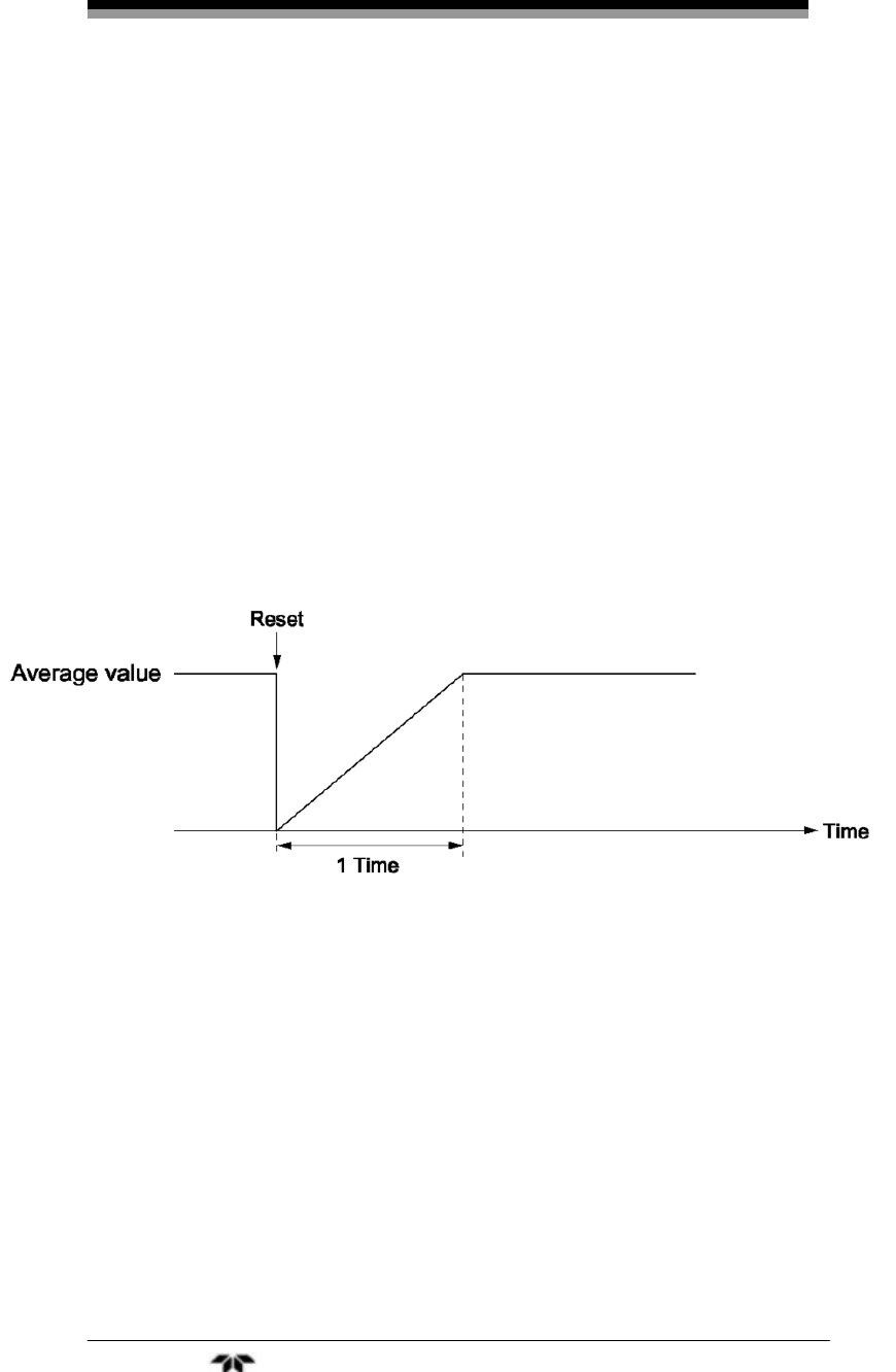
Operation Model 7600
Teledyne Analytical Instruments 80
To modify the average period:
1. Choose the channel or channels you want to modify. You
can set an average time from 1 to 59 minutes in 1-minute
steps or 1 to 4 hours in 1-hour steps.
2. The UP and DOWN keys will increment or decrement
the numerical values while the SIDE key will move the
cursor to the right to the next digit. Press ENT when the
desired value is displayed.
Changing this parameter resets the average value of O2 correction
and O2 average value. Pressing the ENT key validates the resetting only
for components whose setting was changed.
Example of average action:
In the example shown in Figure 3-14, the average period was set to
1 hour.
Figure 3-14: Example Average Period
Sampling occurs every 30 seconds so every 30 seconds the average
for the last 1 hour (time setting) is output.
At the instant of resetting, zero is assumed for all past values. This
means that the average value will be incorrect for 1 hour (1 time period)
after resetting.
3.5.7.5 BACKLIGHT TIMER
Automatic OFF setting of the backlight of the LCD unit can be
adjusted from this menu.
Upon returning to the measurement screen, when the specified time
elapses, the backlight is automatically turned off. During operation,
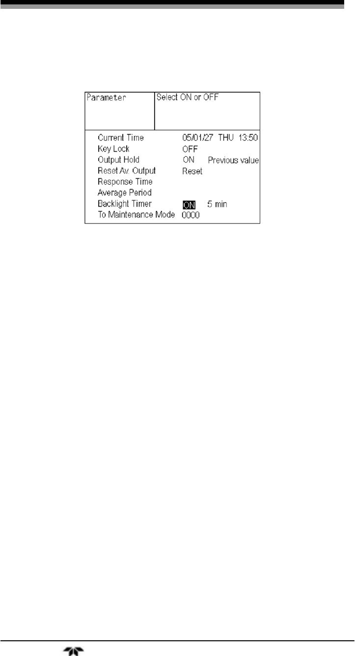
Infrared Gas Analyzer Operation
Teledyne Analytical Instruments 81
pressing any key will turn the backlight back ON for the specified
duration.
When ON is selected, the time until auto OFF is displayed. To
change the backlight automatic shut off time:
1. Select Parameter Setting from the user screen.
2. With the UP or DOWN key, select Backlight Timer. and
press ENT.
3. If the timer is not set to ON, change its state by pressing
the ENT key when OFF is highlighted.
4. Press the SIDE key to move the cursor to the time value
and the time setting can be changed using the UP and
DOWN keys. Press the ENT key to confirm the selection.
Note: When OFF is selected, the backlight remains ON and is
not turned off automatically.
3.5.7.6 MAINTENANCE MODE
The maintenance mode is covered in section 3.6. It is a detailed
password protected set of screens that allows you to check sensor input
values, review error logs, set passwords and more.
The default password setting for entering this mode is “0000.” Use
this password to initially enter the maintenance mode and then change it
to one you can easily remember.
To enter the maintenance mode:
1. From the measurement screen press the MODE key to
open the user mode screen.
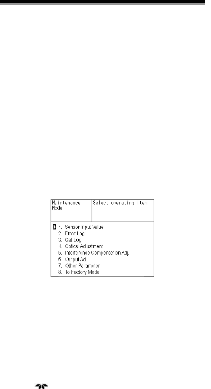
Operation Model 7600
Teledyne Analytical Instruments 82
2. Select Parameter Setting from the user screen.
3. With the UP or DOWN key, select Maintenance Mode
and press ENT.
3.6 Maintenance Mode
This mode is used for checking sensor input values, error log file
display, or setting of passwords, etc. A password is required to enter this
mode.
To get to the maintenance mode screen, select Maintenance Mode
from the Parameter Setting menu. See Section 3.5.7 Parameter Setting.”
This brings up a screen for entering the password. Enter the 4 digit
password using the UP and DOWN keys and the SIDE key to move to
the next digit. Press ENT when complete. If the password is entered
correctly, the maintenance mode screen will appear on the display
offering a range of submenus.
Note: The default password installed in new instruments is
“0000”.
The following submenus are accessed from the maintenance mode
screen:
1. Sensor Input
2. Error Log
3. Calibration Log
4. Optical Adjustment
5. Interference Compensation Adjustment
6. Output Adjustment
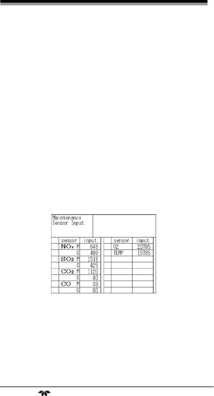
Infrared Gas Analyzer Operation
Teledyne Analytical Instruments 83
7. Additional Parameters
a. Password Set
b. O2 Reference Value
c. Limit
d. MODBUS Communication Station No.
e. Range Setting
8. Factory Mode
In the maintenance mode screen, point the cursor to the item you
want to set by pressing the UP or DOWN key and press the ENT key.
The appropriate screen will automatically display.
Note: “To Factory Mode” is used for factory service engineers.
Do not use this mode.
3.6.1 Sensor Input Value
Upon selecting Sensor Input Value, the following screen will
appear. It lists the installed sensors along with the input value from the
measuring sensor (M) and the compensating detector (C).
Where:
NOx M: NOx sensor input value
NOx C: NOx interference compensation sensor input value
SO2 M: SO2 sensor input value
SO2 C: SO2 interference compensation sensor input value
CO2 M: CO2 sensor input value
CO2 C: CO2 interference compensation sensor input value
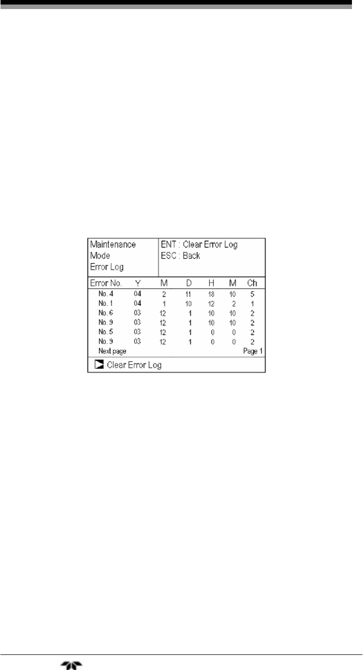
Operation Model 7600
Teledyne Analytical Instruments 84
CO M: CO sensor input value
CO C: CO interference compensation sensor input value
Temperature: temperature sensor input value O2: O2 sensor input
value
3.6.2 Error Log
This screen gives the error history for the last fourteen logged
errors. It also shows the date and time of occurrence (year, month day,
hour, minute) and the channel the error occurred on. For error number,
date and time of occurrence, channel and other details of error, refer to
Section 4.6 Error Messages.
To clear the error log, select Clear Error Log and press the ENT
key.
3.6.3 Calibration Log
The next screens detail the past calibration history on the analyzer.
The first screen allows you to choose the channel whose information
you want displayed. The next screen displays logged information on
sensor input value, concentration value, and the dates when zero/span
calibration were performed for that channel. The last 10 calibration
events are logged for each channel.
The first screen also gives you the opportunity to clear the log. To
erase the log, move the cursor to Clear Calibration Log and press the
ENT key. The calibration log is cleared completely.

Infrared Gas Analyzer Operation
Teledyne Analytical Instruments 85
Z1: Zero calibration (Z) of Range 1
S1: Span calibration (S) of Range 1
M: Value of measuring detector at the time of calibration
C: Value of the interference compensation detector at the time of
calibration
Con: Concentration value displayed before calibration
3.6.4 Optical Adjustment
CAUTION: IF THE OPTICAL ADJUSTMENT IS MADE
INCORRECTLY, ANALYSIS MAY BE ADVERSELY
AFFECTED. CARRY OUT THE OPERATION WITH
UTMOST ATTENTION.
For details of this item, refer to Section4.4 Optical Zero
Adjustment.
Press ENT key and then turn ON the solenoid valve signal for each
calibration gas by using the UP or DOWN keys.
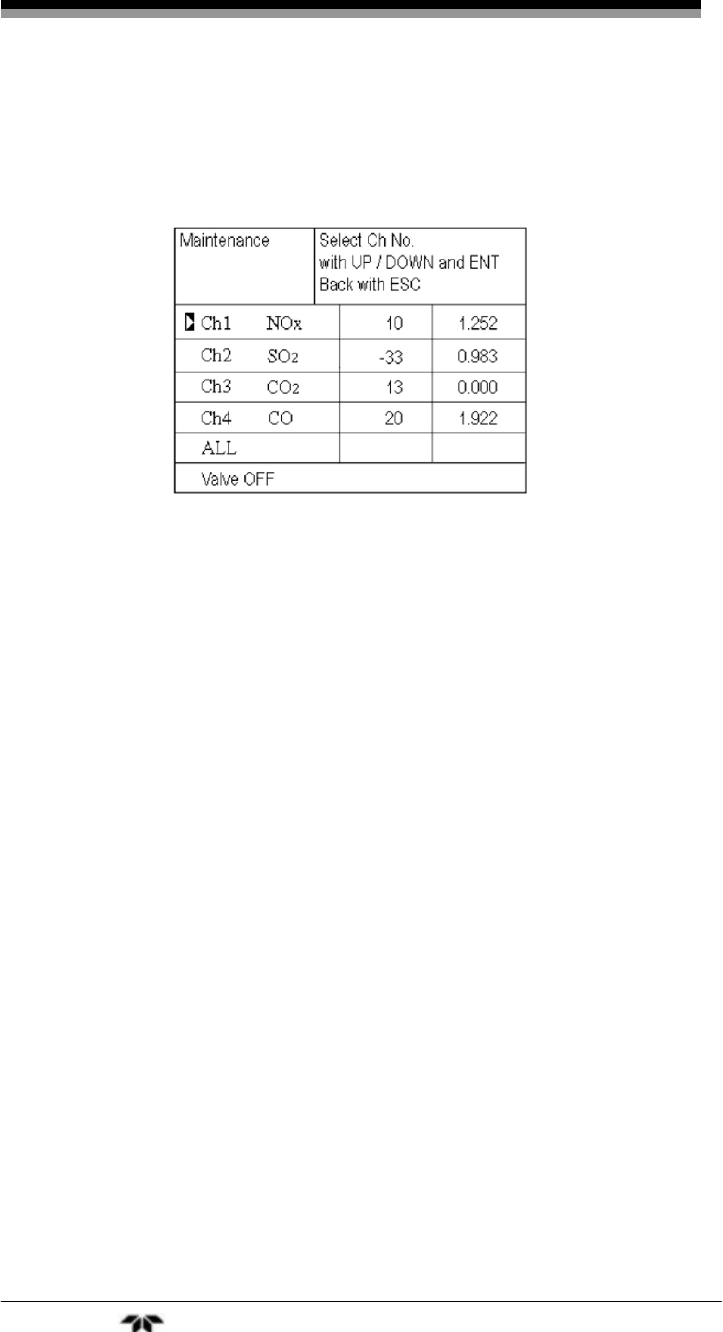
Operation Model 7600
Teledyne Analytical Instruments 86
3.6.5 Moisture Interference Adjustment
This item is described in Section 4.5 Moisture Interference
Adjustment.
For the values listed in the middle column of the screen, the
moisture interference for each component is already offset. The values
in the right column are the interference compensation coefficients used.
To change the coefficient:
1. Move the cursor to a desired channel by pressing the UP
or DOWN key, and then press the ENT key. The
selected interference compensation coefficient at the right
is highlighted.
2. Check that the gas for moisture interference
compensation is flowing. Change the moisture
interference compensation coefficient using the UP or
DOWN key. Adjust the value until the value in the left
column is near zero. Then press the ENT key to log
moisture interference compensation value.
Note: An interference compensation detector is not provided so if
the 1st range is beyond 0 to 10 vol %, no interference
adjustment can be performed (no need).
3.6.6 Output Adjustment Screen
In this menu you can adjust the analog output. First, connect a
digital multi meter to the output terminal corresponding to the output to
be adjusted. See the Appendix for terminal identification on the terminal
blocks. Adjust the value so that 4 mA or 0 V is output at zero and 20
mA or 1 V is output at span.
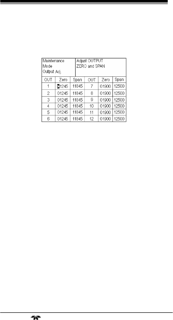
Infrared Gas Analyzer Operation
Teledyne Analytical Instruments 87
1. From the output adjustment screen which accessible from
the maintenance mode menu, move the cursor with the
UP or DOWN key to the output (OUT No. and zero/
span) to be adjusted, and then press the ENT key.
2. The selected value is highlighted. Adjust the value using
the UP or DOWN key while watching the output on the
digital multi-meter. Press the SIDE key to select the next
digit.
3. On completion of the adjustment, press the ENT key.
3.6.7 Other Parameters
The last submenu of the maintenance mode menu contains a group
of parameters that may be modified by the user. These include:
• Password Set: Set the password used to enter the
maintenance mode. An arbitrary 4-digit
number can be selected.
• O2 Ref. Value: Set the oxygen concentration reference
value at the time of oxygen correction
calculation. Settable in the range from 00
to 19%.
• Limit: Set the oxygen concentration limit at the
time of oxygen correction calculation.
Settable in the range from 01 to 20%. See
O2 correction concentration value in
Section 3.3.1 Measurement Mode for
oxygen correction calculation procedure.

Operation Model 7600
Teledyne Analytical Instruments 88
• Station No.: Set the station No. for MODBUS
communication. Settable in the range from
00 to 32.
• Range setting: Moves to the screen on which measuring
range is changed.
To adjust or make changes to these parameters:
1. Press the UP or DOWN key to move the cursor to the
item whose setting is to be changed.
2. The values for password, oxygen correction, limit, and
station no. are highlighted.
3. Press the UP or DOWN key to change the value and then
press the ENT key.
Note: If you forget the password you will be locked out from the
maintenance mode. Keep a record of the password in a
secure place. Contact the factory for instruction on
reclaiming forgotten or lost passwords.
To set or change the range:
The measuring range can be arbitrarily selected in the minimum
and the maximum range specified at the time of purchase. The range to
be used can be selected as 1 or 2.
1. Move the cursor to the Range Setting option using the UP
or DOWN key, and then press the ENT key.
2. This brings up another screen that lists the channels and
components. Move the cursor to the channel whose
setting is to be changed by pressing the UP or DOWN
key, and then press the ENT key.

Infrared Gas Analyzer Operation
Teledyne Analytical Instruments 89
3. Another screen appears which displays the current MIN
and MAX ranges established for that component. To
change the existing range move the cursor to the range
you want to modify using the UP or DOWN key, and
then press the ENT key.
Note: The value for range 1 and range 2 must fall within or be
equal to the MIN the MAX range and range 1 must be less
than range 2.
The number of ranges (Range num.) is 1 or 2.
4. Press the UP or DOWN key to change the value. Press
the SIDE key to select the next digit. When the decimal
point is highlighted, press the UP or DOWN key, and the
decimal point position can be changed.
5. When complete, press the ENT key to save the change.
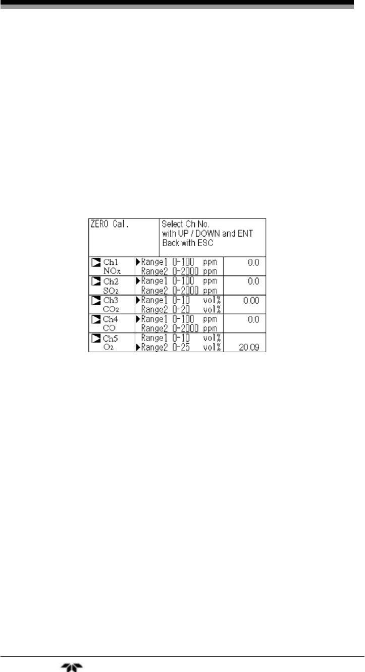
Operation Model 7600
Teledyne Analytical Instruments 90
3.7 Calibration
3.7.1 Zero Calibration
The zero calibration is used for zero point adjustment. A suitable
zero calibration gas is described in Section 2.5.5 Preparation of
Calibration Gas.
To zero calibrate the analyzer:
1. Press the ZERO key on the Measurement screen to
display the Manual Zero Calibration screen.
2. Select the channel to be calibrated by pressing the UP or
DOWN key. After selection, press the ENT key, and zero
gas will be supplied.
Note: For channels that are set to “both” in the “Zero Calibration”
of the Calibration Setting mode, the zero calibrations are
carried out at the same time.
3. Wait until the display has stabilized with the zero gas
flowing. After stabilization, press the ENT key. At this
point, the zero calibration on the range indicated by the
cursor is carried out.
Note: If the selected channel was set for autoranging “AR” (see
Section 3.5.1 Switch Ranges. the cursor automatically
moves to the range selected in “Setting of Auto Calibration
Component/ Range” (Section 3.5.2.4), and calibration is
carried out within that range.
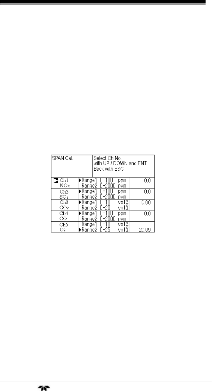
Infrared Gas Analyzer Operation
Teledyne Analytical Instruments 91
To close the “Zero Calibration” screen or cancel this mode
midway, press the ESC key. A previous screen will return.
3.7.2 Span Calibration
Span calibration is used to perform a span point adjustment. It
requires a span gas with a known concentration, preferably 90% or more
of the range value of the component being calibrated. For oxygen, when
measuring with the built-in O2 use a standard gas containing 90% or
more of the range value. Use a standard gas of about 2 vol % when
measuring with an external zirconia O2 sensor.
To span calibrate the analyzer:
1. From the measurement screen press the SPAN key to
display the Manual Span Calibration screen.
2. Select the channel to be calibrated by pressing the UP or
DOWN key. Then press the ENT key and the calibration
gas will be supplied.
Note: For channels that are set to “both” in the “Span Calibration”
of the Calibration Setting mode, the span calibrations will
be carried out for each component.
3. Wait until the display has stabilized with the span gas
flowing. After stabilization, press the ENT key. Span
calibration on the range selected by the cursor is performed.
Note: If the selected channel was set for autoranging “AR” (see
Section 3.5.1 Switch Ranges. the cursor automatically
moves to the range selected in “Setting of Auto Calibration
Component/ Range” (Section 3.5.2.4), and calibration is
carried out within that range.

Operation Model 7600
Teledyne Analytical Instruments 92
To close "Span Calibration"
To close the “Span Calibration” screen or cancel this mode
midway, press the ESC key. A previous screen will return.

Infrared Gas Analyzer Maintenance
Teledyne Analytical Instruments 93
Maintenance
4.1 Routine Maintenance
Aside from normal cleaning of the instrument and making sure
connections are tight and secure, the following maintenance items
should be carried out on a daily basis.
1. Zero and Span Calibration:
Perform a zero calibration. For the calibration
procedures, refer to Section 3.7.1 Zero Calibration.
Then, perform span calibration. For the calibration
procedures, refer to Section 3.7.2 Span Calibration.
2. Flowrate Check:
Sampling and purge gas flowrates are as follows:
Sampling gas flow: 0.5L/min 0.2 L/min
Purge gas flow: About 1 L/min
Check and adjust if necessary every day.
4.2 Daily Check and Maintenance Procedures
Table 4.1 Troubleshooting and Maintenance
Item to be
checked Phenomena Cause Remedy
Display value Display values are
low.
Display values are
high.
(1) Dust is
mixed in
sampling cell.
(1) Clean the
sampling cell.
Check
sampling
system
especially gas
filter.
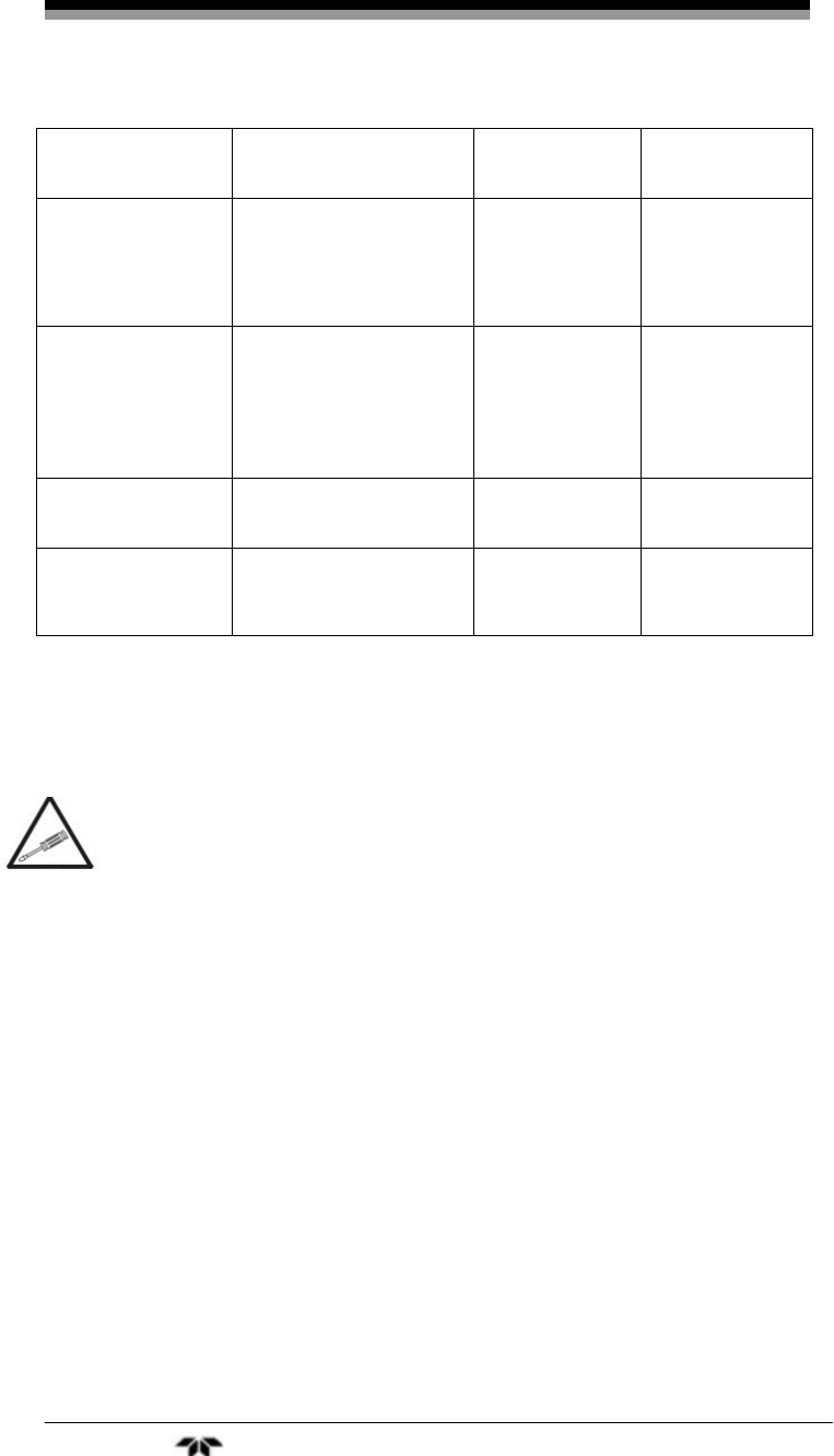
Maintenance Model 7600
Teledyne Analytical Instruments 94
Item to be
checked Phenomena Cause Remedy
(2) Air is
absorbed
midway in the
sampling pipe.
(2) Find cause
of leak and
repair.
Purge gas flow is
included when
purge gas in
sampling gas
flow rate.
Standard flow is
beyond the specified
flow rate of 0.5 L/min,
0.3 to 0.7 L/min.
Adjust using
needle valve
on flowmeter.
Zero point of gas
analyzer It is deflected. Adjust.
Span point of
gas analyzer It is deflected. Adjust.
4.3 Analyzer Maintenance
4.3.1 Sample Cell Cleaning
In rare circumstances will the sample cell require cleaning.
The procedure for dismantling and cleaning the sample cell
should be handled by qualified personnel only. In general,
if it is absolutely required, contact the factory.
The recommended procedure for cleaning the sample cell is as
follows:
1. Turn off the power switch, stop the sample gas, and
allow the zero gas to flow for several minutes to purge
the cell interior.
2. Loosen the setscrew (2 pieces) from the top cover and
remove it as shown in Figure 4-1.
3. Remove the internal gas inlet tube.
4. Loosen both right and left screws for cell holding plate
and remove only the sample cell. See Figure 4-2.
5. Turn the sample cell window to the left and remove it
from the sample cell. See Figures 4-3 and 4-4.
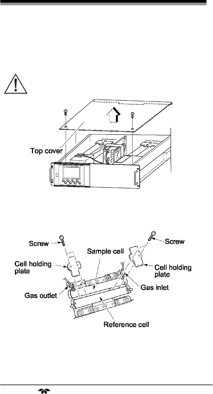
Infrared Gas Analyzer Maintenance
Teledyne Analytical Instruments 95
6. For cleaning the window and inside surface of the cell,
first eliminate coarse dust using a soft brush and then
wipe with a soft rag.
CAUTION: THE WINDOW IS EASILY SCRATCHED. USE
EXTREME CARE WHEN PERFORMING THIS
OPERATION SO AS NOT TO DAMAGE IT.
Figure 4-1: Top Cover Removal
Figure 4-2: Sample Cell Removal
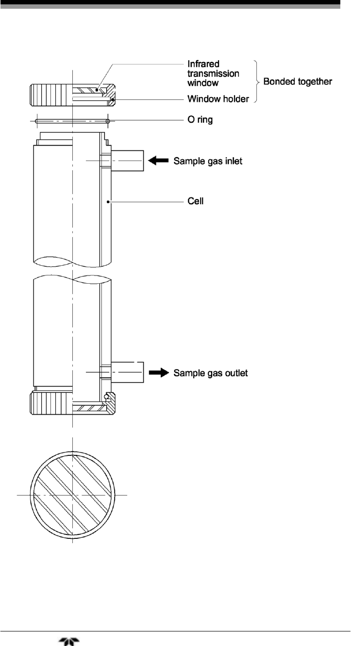
Maintenance Model 7600
Teledyne Analytical Instruments 96
Figure 4-3: Sample Cell

Infrared Gas Analyzer Maintenance
Teledyne Analytical Instruments 97
Figure 4-4: IR Window Assembly
Note: If the window or the cell interior is very dirty, gently wipe it
using a soft cloth moistened with absolute alcohol. A
slightly corroded infrared transmission window/sample cell
can be remedied by gentle rubbing with chromium oxide
powder on a cleani cloth but if excessively corroded, it
must be replaced. Do not use excessive force when
cleaning the window.
Reinstall the cell after cleaning. Be sure to perform an optical zero
adjustment (Section 4.4) and moisture interference compensation
adjustment (Section 4.5) prior to analysis.
4.3.2 Cleaning the Cell Block
1. Turn off the power switch, stop the sample gas, and allow
the zero gas to flow for several minutes to purge the cell
interior.
2. Loosen the 2 setscrews that secure the top cover and
remove it.
3. Remove the internal gas inlet tube.
4. Loosen the 2 detector set bolts. See Figure 4-5.
Note: The gas distribution block, cell block, and detector are
fastened by the same bolts.
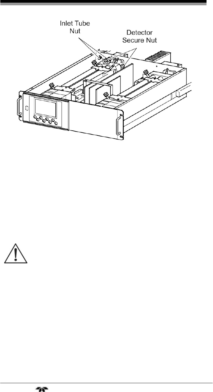
Maintenance Model 7600
Teledyne Analytical Instruments 98
Figure 4-5: Detector Secure Nut
5. Using the furnished cell mounting tool, turn the window
fixture to the left and remove it from the cell. See Figure
4-6.
6. For cleaning the infrared transmission window and cell
inside surface, first eliminate coarse dust using a soft
brush and then wipe clean with a soft rag.
CAUTION: THE WINDOW IS EASILY SCRATCHED. USE
EXTREME CARE WHEN PERFORMING THIS
OPERATION SO AS NOT TO DAMAGE IT.
7. After cleaning, reinstall the sample cell and perform an
optical zero adjustment (see Section 4.4) and moisture
interference compensation adjustment (see Section 4.5).
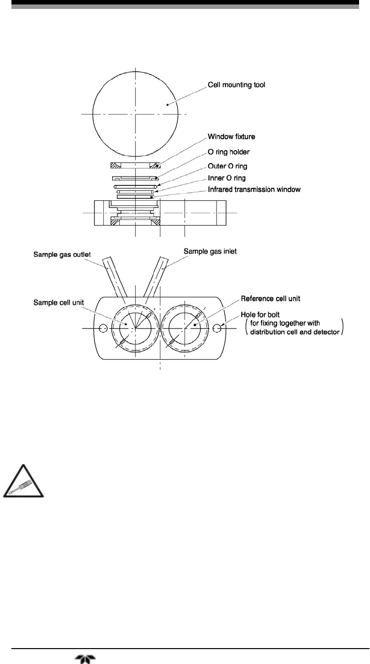
Infrared Gas Analyzer Maintenance
Teledyne Analytical Instruments 99
Figure 4-6: Cell Block Assembly
4.4 Optical Zero Adjustment
If the following operation is not performed correctly,
subsequent analysis may adversely be affected. This
operation should be performed by a trained technician or
the unit sent back to the factory for service.
The following adjustment is performed at reassembly after
removing and cleaning the sample cell.
1. Remove the top cover.
2. Allow dry N2 or air to flow through the analyzer sample
gas inlet until the reading stabilizes. The sample gas is
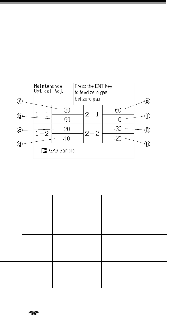
Maintenance Model 7600
Teledyne Analytical Instruments 100
introduced directly to the inlet of analyzer unit through
the gas cylinder.
3. Proceed to an optical adjustment as described in the
maintenance mode. The display on the operation panel of
the main unit is illustrated in Figure 4-7. Balance adjust-
ment is not required if the display falls within ±100.
Figure 4-7: Optical Adjustment Display for Dual Optical System
Option
Table 4-2: Components of Optical Adjustment Screen
No. Of Components
to be measured a b c d e f g h
1-component meter Main Comp – – – – – –
NO/SO2 NO
Main
NO
Comp
SO2
Main
SO2
Comp – – – –
CO2/CO CO2
Main
CO2
Comp
CO
Main
CO
Comp –
2-
component
meter
NO/CO NO
Main
NO
Comp – –
CO
Main
CO
Comp – –
3-component meter
NO/SO2/CO
NO
Main
NO
Comp
SO2
Main
SO2
Comp
CO
Main
CO
Comp – –
4-component meter
NO/SO2/CO2/CO
NO
Main
NO
Comp
SO2
Main
SO2
Comp
CO2
Main – CO
Main
CO
Comp

Infrared Gas Analyzer Maintenance
Teledyne Analytical Instruments 101
Where:
“Main” is signal input value from the main detector of each component.
“Comp” is signal input value from interference compensation detector of
each component. If low range exceeds the range of 0 to 10 vol %,
detector signal of “comp” is not usable.
In the above table, O2 is excluded from the number of components.
Sensor values which are not included in measuring components
should be ignored.
4. Adjust the primary side of the optical system (if
instrument is equipped with more than 1 measuring unit)
so that the onscreen values for (a) to (d) in 1-1 and 1-2 of
become as close to 0 as possible within ±100 range.
5. Adjust on the secondary side of the optical system so that
the values for (e) to (h) in 2-1 and 2-2 become as close to
0 as possible within ±100 range.
6. Operate the optical zero adjustment knob to change the
value displayed at (a) or (e). See Figure 4-8
Figure 4-8: Optical Zero Adjustment
7. Move the beam adjustment plate sideways to change the
value displayed at (b) or (f ). See Figure 4-9.
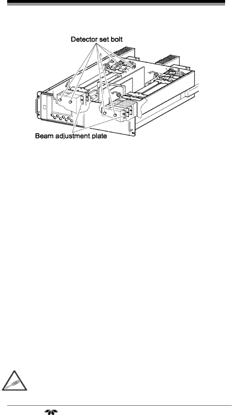
Maintenance Model 7600
Teledyne Analytical Instruments 102
Figure 4-9: Beam Adjustment Plate
8. Move the beam adjustment plate sidewise to change the
value displayed at (c) or (g).
9. Move the beam adjustment plate sidewise to change the
value displayed at (d) or (h).
10. Repeat the procedures in (6) to 9) to make all the
displayed values come close to 0 as possible within ±100
range.
Note: Adjust the beam adjustment plate which is the nearest to
the zero adjustment knob first, and sequentially.
11. After the optical balance adjustment, remount the top
cover of the analyzer unit, then carry out a moisture
interference compensation adjustment, and perform zero
and span calibrations.
Note: Before moving the beam adjustment plate, loosen the
detector set bolts (just enough to make the plate movable
for snug adjustment.
4.5 Moisture Interference Compensation Adjustment
If the following operation is not performed correctly,
subsequent analysis may adversely be affected. This
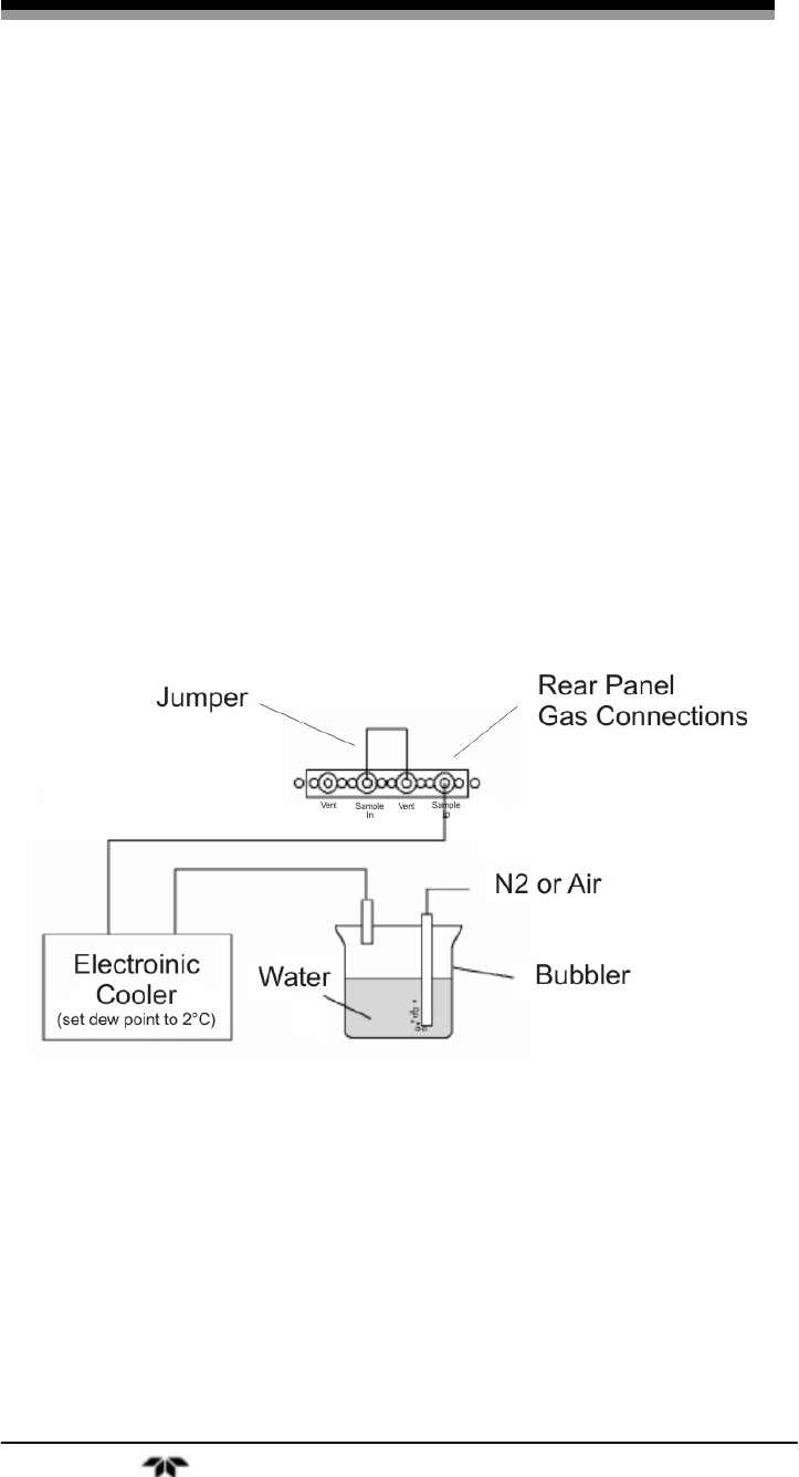
Infrared Gas Analyzer Maintenance
Teledyne Analytical Instruments 103
operation should be performed by a trained technician or
the unit sent back to the factory for service.
Perform an adjustment if excessively (beyond ±2% FS) affected by
moisture inteference.
It is also necessary to adjust moisture interference compensation
after making an optical balance adjustment or whenever the cell
structure is opened to moist air.
1. After warm-up, select the low range and allow dry gas
(N2 or air) to flow at 0.5 L/min and zero calibrate the
analyzer.
2. Display the moisture interference compensation screen of
the analyzer unit (see Section 3.6.5 Moisture Interference
Adjustment). Set the dew point to 2°C by using an
electronic cooler, and introduce bubbled N2 or air to the
analyzer (shown in the Figure 4-10).
Figure 4-10: Bubbler Apparatus
3. On the screen, select a desired channel by using the UP
and DOWN keys then pressing ENT when the cursor is
on the desired channel.
4. Use the SIDE key to move the cursor to the numerical
value in the right column. Adjust the value by the UP or
DOWN key so that the value at left falls within ±10 (or as
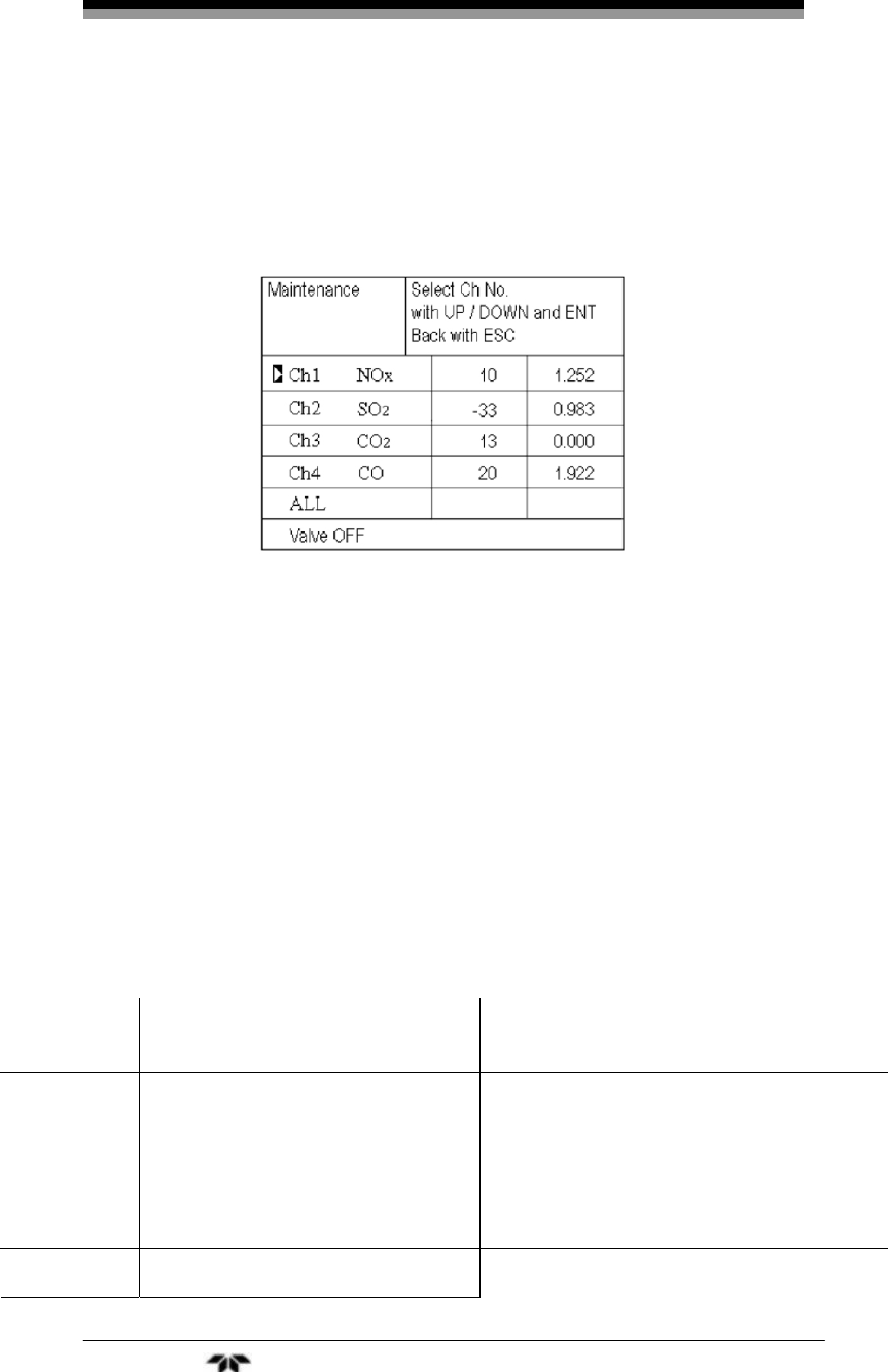
Maintenance Model 7600
Teledyne Analytical Instruments 104
close to 0 as possible), and then press the ENT key to
save the value. Alternatively, by selecting the
“ALL”option and pressing the “ ENT ” key, you can zero
all components at once. You can abort the process at any
time by pressing the “ ESC ” key.
5. It is sometimes easier to adjust all components by
selecting ALL and then perform fine adjustment for
components one by one using UP and DOWN keys.
Note: If any components exceed the range of 0 to 10 vol %, no
adjustment can be performed (No interference
compensation is required).
4.6 Error Messages
You may encounter an onscreen error message depending on the
process state or operational error. The following table describes typical
error messages and their cause.
Table 4-3: Error Messages
Error
Display Error Contents Probable Cause
Error No.1 Motor rotation detection signal
faulty.
• Motor rotation is faulty or stopped.
• Motor rotation detector circuit is faulty.
Note: Sector motor is a consumable
item. It is recommended to exchange
the motor once every two years.
Error No.4 Zero gas not flowing • Zero gas is not supplied.
Infrared Gas Analyzer Maintenance
Teledyne Analytical Instruments 105
Error
Display Error Contents Probable Cause
Error No.5 Amount of zero calibration
(indication value) is over 50% of
full scale.
• Zero is deflected much due to dirty
cell.
• Detector is faulty.
• Optical balance is out of adjustment.
Error No.6 Span calibration is not within the
allowable range.
Error No.7 Amount of span calibration
(difference between indication
value and calibrated
concentration) is over 50% of full
scale.
• Span gas is not supplied.
• Calibrated concentration setting does
not match cylinder concentration.
• Zero calibration was performed
incorrectly.
• Dirty cell.
• Detector sensitivity has deteriorated.
Error No.8 Measured values fluctuate too
much during zero and span
calibration.
• Calibration gas is not supplied.
• Time for flowing calibration gas is too
short.
Error No.9 Calibration is abnormal during
auto calibration. • No. 4 to No. 8 Error occurred during
Error No.10 Output cable connection is
improper. • Wiring is detached between analyzer
and interface module.
• Wiring is disconnected between
analyzer and interface module.
When errors No. 1 and No. 10 occur, the analyzing block error
contact is closed. When errors No. 4 to No. 9 occur, calibration error
contact is closed.
When an error occurs, the error number message will appear at the
offending channel. The screen below shows that error No. 9 has
occurred on Channel 1.

Maintenance Model 7600
Teledyne Analytical Instruments 106
Pressing ENT displays the error contents screen which describes
the error, indicates what channel or component is affected and suggests
probable causes for the error.
If the ESC key is pressed without removing the cause of an error,
the error will be displayed again. When more than one error occurs,
pressing the SIDE key moves to another error display.
4.6.1 Error Log File
If error occurs, the history is saved in an error log file. The error log
file exists in the maintenance mode.
4.6.2 Error Log Screen
Up to 14 errors can be saved in the error history; the oldest error
will be deleted one by one each time a new error occurs. Figure 4-11
shows the Error Log screen and identifies the fields.
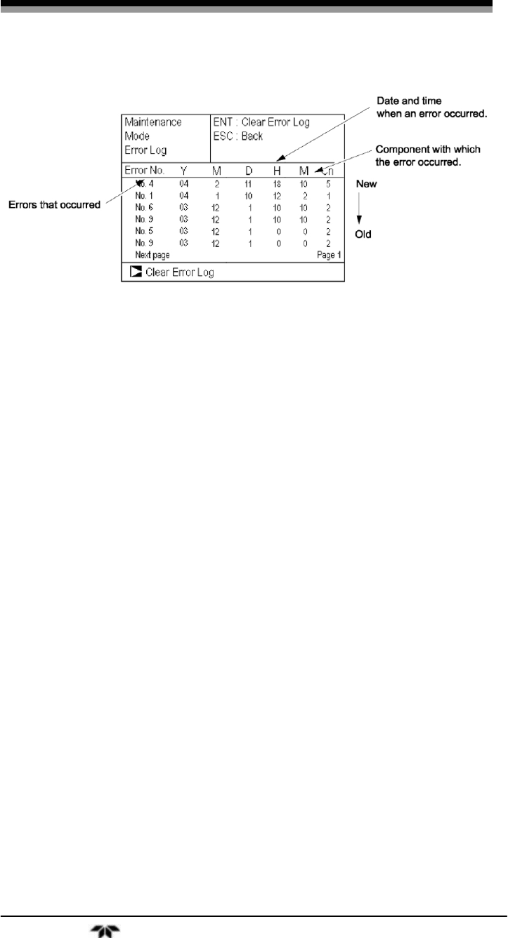
Infrared Gas Analyzer Maintenance
Teledyne Analytical Instruments 107
Figure 4-11: The Error Log Screen
If the power supply is turned OFF, the contents in the error log file
will not be lost or damaged.
4.6.3 Deleting Error Hstory
Press the ENT key on the above screen, and the “Error Log Clear”
will be inverted. Pressing the ENT key again will clear the error history.

Maintenance Model 7600
Teledyne Analytical Instruments 108

Infrared Gas Analyzer Appendix
Teledyne Analytical Instruments 109
Appendix
A.1 SPECIFICATIONS
General Specifications
Standard specifications
Measurable components: Max. 5 components including O2.
Minimum range Maximam range
NO 0 – 50ppm 0 – 5000ppm
SO2 0 – 50ppm 0 – 10vol %
CO2 0 – 20ppm 0 – 100vol %
CO 0 – 50ppm 0 – 100vol %
CH4 0 – 200ppm 0 – 100vol %
O2 (built in) 0 – 5vol % 0 – 25vol %
O2 (Ext. Zirconia) 0 – 5vol % 0 – 25vol %
Ranges: 2 each channel, user settable between
Max. and Min.
Measuring Range Ratio: ≤ 1:5 (O2)
≤ 1:25 (other than O2)
Principle of measurement:
(NO, SO2, CO2, CO): Non-dispersion infrared-ray absorption
Single light source and double beam
(double-beam system)
O
2: Paramagnetic O2 sensor (built in) or zir
conia O2 sensor (externally installed)
Display: 4-digit digital LCD display with back light

Appendix Model 7600
Teledyne Analytical Instruments 110
Analog Output: 12 points max.
4 to 20 mA DC or 0 to 1V DC, non-
isolated output
max.load 550Ω for 4 to 20 mA DC
min.load 100kΩ for 0 to 1VDC
Analog Input: 0 to 1V DC non-isolated input from
externally installed Zirconia type O2
sensor.
Relay Contact Output: 1a contact (250V AC/2A, resistive load)
Instrument error, calibration error, range
identification, auto calibration status,
pump ON/OFF, peak alarm.
1c contact (250V AC/2A, resistive load
selectable 6 outputs). High/Low limit
alarm contact output. Power disconnection
alarm.
Contact Input: No-voltage contact (ON/0V, OFF/5V
DC, 5mA flowing at ON)
Remote range switch, auto calibration
remote start, remote holding, average
value resetting, pump ON/OFF
Isolated from the internal circuit with
photocoupler. Contact inputs are not iso-
lated from one another.
Other Output: Solenoid valve drive signal for automatic
calibration.
Transistor output (100mA or less)
Power Supply: Voltage rating: 100V to 240V AC
Allowable range: 85V to 264V AC
Frequency: 50Hz/60Hz
Power consumption: 250VA max.
Inlet: Conforms to EN60320 Protection Class 1

Infrared Gas Analyzer Appendix
Teledyne Analytical Instruments 111
Operating conditions: Ambient temperature: -5°C to 45°C
Ambient humidity: 90% RH max., non-
condensing
Storage Conditions: Ambient temperature: -20°C to 60°C
Ambient humidity: 100% RH max.,
non-condensing
Dimensions: Analyzer main unit: 177 x 483 x 600mm
Input/output module: 164 x 318 x 55mm
Weight: Approx. 22 kg (Analyzer only)
Internal Sample System
Wetted Parts: Gas inlet/outlet: SUS304
Sample cell: SUS304,chloroprene
rubber
IR window: CaF2 O2
sensor sample cell: SUS316
Internal piping: Toaron, Teflon
Gas Inlet/Outlet: Rc1/4 or NPT1/4 internal thread
Purge Gas Flowrate: 1L/min (when required)
A.2 Standard Functions
Output signal holding: Output signals are held during manual and
auto calibrations by activation of holding
(turning “ON” its setting).
The values to be held are the ones just
before start calibration mode or setting
value. Selectable.
Indication of instantaneous values will not
be held.
Remote output holding: Output signal is held at the latest value or
setting value by short-circuiting the
remote output holding input terminals.
Holding is maintained while the terminals

Appendix Model 7600
Teledyne Analytical Instruments 112
are short-circuited. Indication of instanta-
neous values will not be held.
Range switching: Range switching is available in manual,
auto, and remote modes. Only preset
switch method is effective.
Manual: Allows range to switch by key
operation.
Auto: Allows range to switch from low to
high range when 90%FS or more is
available in the low range.
Allows range to switch from high to low
range when 80%FS or less is available in
the low range.
Remote: No-voltage contact input (for
measurable components)
Allows range to switch via an external
signal when remote range switch input is
received.
When the contact input terminals for each
component are short-circuited, the first
range is selected, and it is switched to the
second range when the terminals are open.
Range identification signal: The present measuring range is identified
by a contact signal.
The contact output terminals for each
component are short-circuited when the
first range is selected, and when the
second range is selected, the terminals are
open.
Auto calibration: Auto calibration is carried out periodically
at the preset cycle.
When a standard gas cylinder for calibra-
tion and a solenoid valve for opening/clos-
ing the gas flow line are prepared
externally by the customer, calibration

Infrared Gas Analyzer Appendix
Teledyne Analytical Instruments 113
will be carried out with the solenoid valve
drive contacts for zero calibration and
each span calibration turned on/off
sequentially at the set auto calibration
timing.
Auto calibration cycle setting:
Auto calibration cycle is set.
Setting is variable within 1 to 99 hours (in
increments of 1 hour) or 1 to 40 days (in
increments of 1 day).
Gas flow time setting:
The time for flowing each calibration gas
in auto calibration is set. Settable within
60 to 900 seconds (in increments of 1
second)
Auto calibration remote start: Auto calibration is carried out only
once according to an external input signal.
Calibration sequence is settable in the
same way as the general auto calibration.
Auto calibration is started by opening the
auto calibration remote start input termi-
nals after short-circuiting for 1.5 seconds
or longer.
Auto zero calibration: Auto zero calibration is carried out
periodically at the preset cycle.
This cycle is independent of “Auto
calibration” cycle.
When zero calibration gas and solenoid
valve for opening/closing the calibration
gas flow line are prepared externally by
the customer, zero calibration will be car-
ried out with the solenoid valve drive con-
tact for zero calibration turned on/off at
the set auto zero calibration timing.
Auto zero calibration cycle setting:
Auto zero calibration cycle is set.

Appendix Model 7600
Teledyne Analytical Instruments 114
Setting is variable within 1 to 99 hours (in
increments of 1 hour) or Setting is variable
within 1 to 40 days (in increments of 1
day)
Gas flow time setting:
The timing for flowing zero gas in auto
zero calibration is set.
Settable 60 to 900 seconds (in increments
of 1 second)
Upper/lower limit alarm: Alarm contact output turns on when mea-
surement value reach to the preset high or
low limit alarm value.
Contacts close when the channel value of
each channel becomes larger than the high
alarm limit value or smaller than the low
alarm limit value.
Instrument error contact output:
Contacts close at occurrence of analyzer
error No. 1, 3 or 10.
Calibration error contact output:
Contacts close at occurrence of manual or
auto calibration error (any of errors No. 4
to 9).
Auto calibration status contact outputs:
Contacts close during auto calibration.
Pump ON/OFF contact output:
During measurement, this contact close.
While calibration gas is flowing, this con-
tact open. This contact is connected in
power supply of pump, and stop the
sample gas while calibration gas flowing.

Infrared Gas Analyzer Appendix
Teledyne Analytical Instruments 115
A.3 Optional Functions
O
2 correction: Correction of measured NO, SO2 and CO
gas concentrations into values at reference
O2 concentration
Correction formula: Cs
Os-21
On-21
C×=
C: Sample gas concentration after O2
correction
Cs: Measured concentration of sample gas
Os: Measured O2 concentration (Limit setting:
1 to 20% O2)
On: Reference O2 concentration (value
changeable by setting. 0 to 19% O2)
Average value after O2 correction and O2 average value calculation:
The result of O2 correction or instanta-
neous O2 value can be output as an av-
erage value in the preset period of time.
The moving average method is used for
averaging in which sampling is carried out
at intervals of 30 seconds.
Output is updated every 30 seconds. It is
the average value in the determined period
of time just before the latest update.
Averaging time is settable within 1 to 59
minutes (in increments of 1 minute) or 1
to 4 hours (in increments of 1 hour).
Average value resetting: The above-mentioned output of average
value is started from the initial state by
opening the average value resetting input
terminals after short-circuiting for 1.5 sec-
onds or longer.
Output is reset by short-circuiting and re-
started by opening

Appendix Model 7600
Teledyne Analytical Instruments 116
CO concentration peak count alarm: (added only for CO/O2
measurement) Alarm output turns on
according to the pre-set concentration and
count.
Whenever the instantaneous value of CO
exceeds the preset concentration value,
count increments. If the count exceeds the
preset value in one hour, the alarm
contacts close.
Communication function: RS-232C (9 pin D-sub)
Half-duplex bit serial
Start-stop synchronization
Modbus TM protocol
Contents:
Read/Wright parameters
Read measurement concentration and
instrument status
Remark:
When connecting via RS-485
interface, a RS-232C↔RS-485
converter should be used.
A.4 Performance:
Repeatability: ±0.5% of full scale
Linearity: ±1% of full scale
Zero drift: ±1% of full scale/week
(±2% of full scale/week; range between 0
to 50ppm and 0 to 200ppm)
(±2% of full scale/day; below 0 to 50 ppm
range)
Span drift: ±2% of full scale/week
(±2% of full scale/day; below 0 to 50 ppm
range)

Infrared Gas Analyzer Appendix
Teledyne Analytical Instruments 117
Response time (90%): 15 sec electrical response.
Within 60 seconds including replacement
time of sampling gas (with 0.5L/min gas
flow rate). Gas replacement time depends
on the number of components,and
measuring range.
A.5 Standard Requirements for Sample Gas
Flowrate: 0.5L / min ±0.2 L/ min
Temperature: 0 to 50°C
Pressure: 10 kPa (1.45 psi) or less (Gas outlet side
should be open to the atmospheric air.)
Dust: 100 g/Nm3 in particle size of 1μm or less
Mist: Unallowable
Moisture: Below saturation at 2°C (condensation un-
allowable).
Corrosive component: 1 ppm or less
Standard gas for calibration: Zero gas: Dry N2
Span gas: Each sample gas having
concentration 90 to 100% of its measuring
range (recommended). Concentration
above 100% FS is unusable.
If an external zirconia O2 sensor is
installed and calibration is carried out on
the same calibration gas line:
Zero gas: Dry air or atmospheric air
(provided without CO2 sensor).
Span gas: For other than O2 measurement,
each sample gas having concentration 90
to 100% of its measuring range.
For O2 measurement: O2 gas of 1 to 2 vol
%.

Appendix Model 7600
Teledyne Analytical Instruments 118
A.6 Installation Requirements
• Indoor use. Select a place where the equipment does not
receive direct sunshine, draft/rain or radiation from hot
substances. If such a place cannot be found, a roof or cover
should be prepared for protection.
• Avoid a location that is subject to heavy vibration.
• Select a location where atmospheric air is clean.
A.7 EC Directive Compliance
The product conforms to the requirements of the Low Voltage
Directive 73/23/EEC and EMC directive 89/336/EEC (as amended by
Directive 92/31/EEC), both as amended by Directive 93/68/EEC.
It conforms to following standards for product safety and
electromagnetic compatibility;
• EN61010-1: 2001 Safety requirements for electrical
equipment for measurement, control and laboratory use.
“Installation Category II” “Pollution Degree 2”
• EN61326-1: 1997, AI: 1998, A2: 2001 Electrical equipment
for measurement, control and laboratory use — EMC
requirements.
* The product mounted in a steel enclosure conforms to the
requirements of EMC directive.
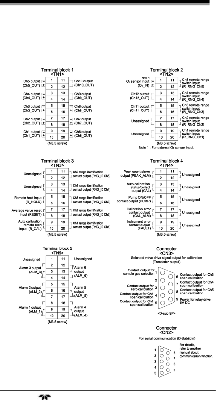
Infrared Gas Analyzer Appendix
Teledyne Analytical Instruments 119
A.8 Terminal Block Connections
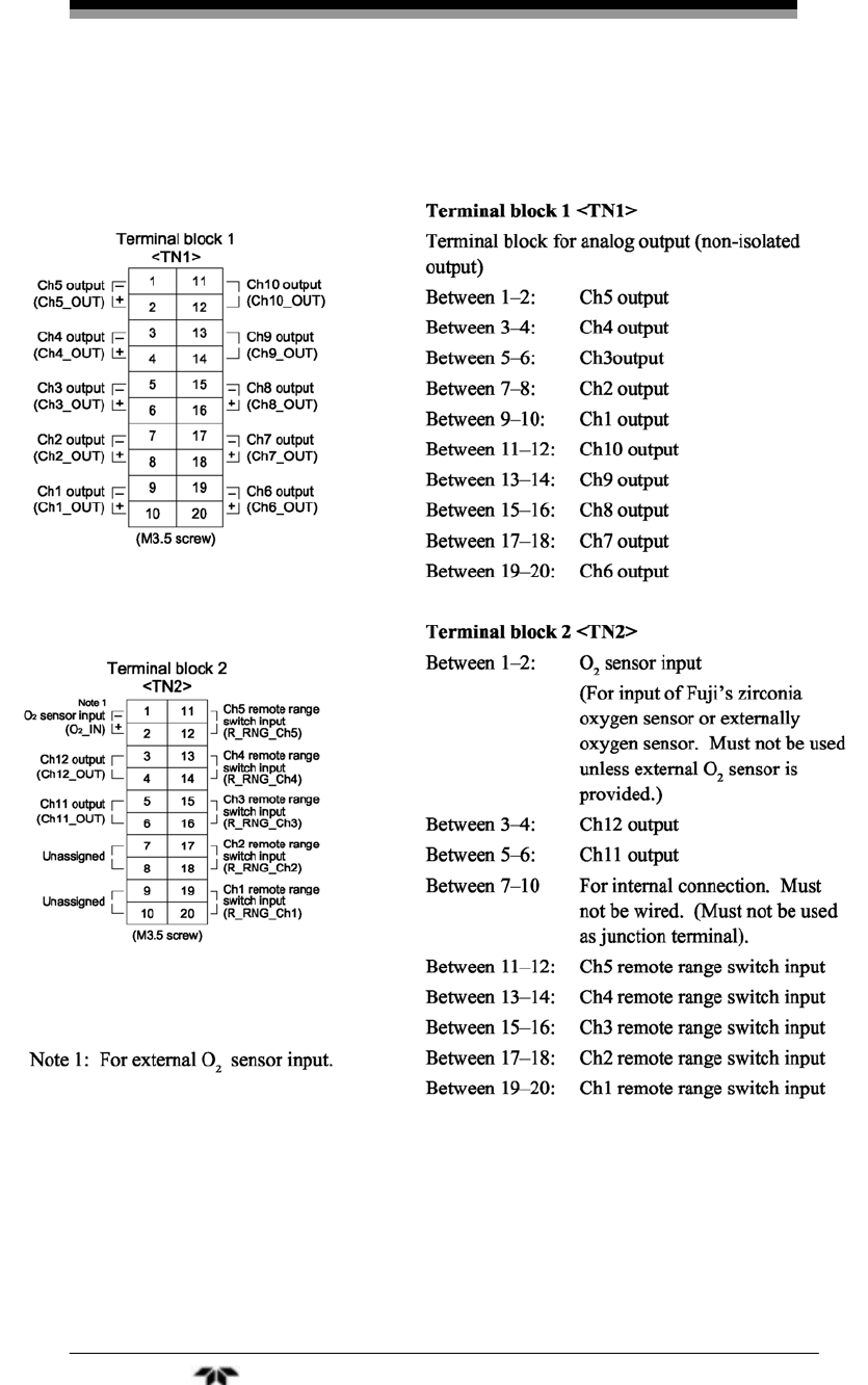
Appendix Model 7600
Teledyne Analytical Instruments 120
A.9 Description on Terminal Block
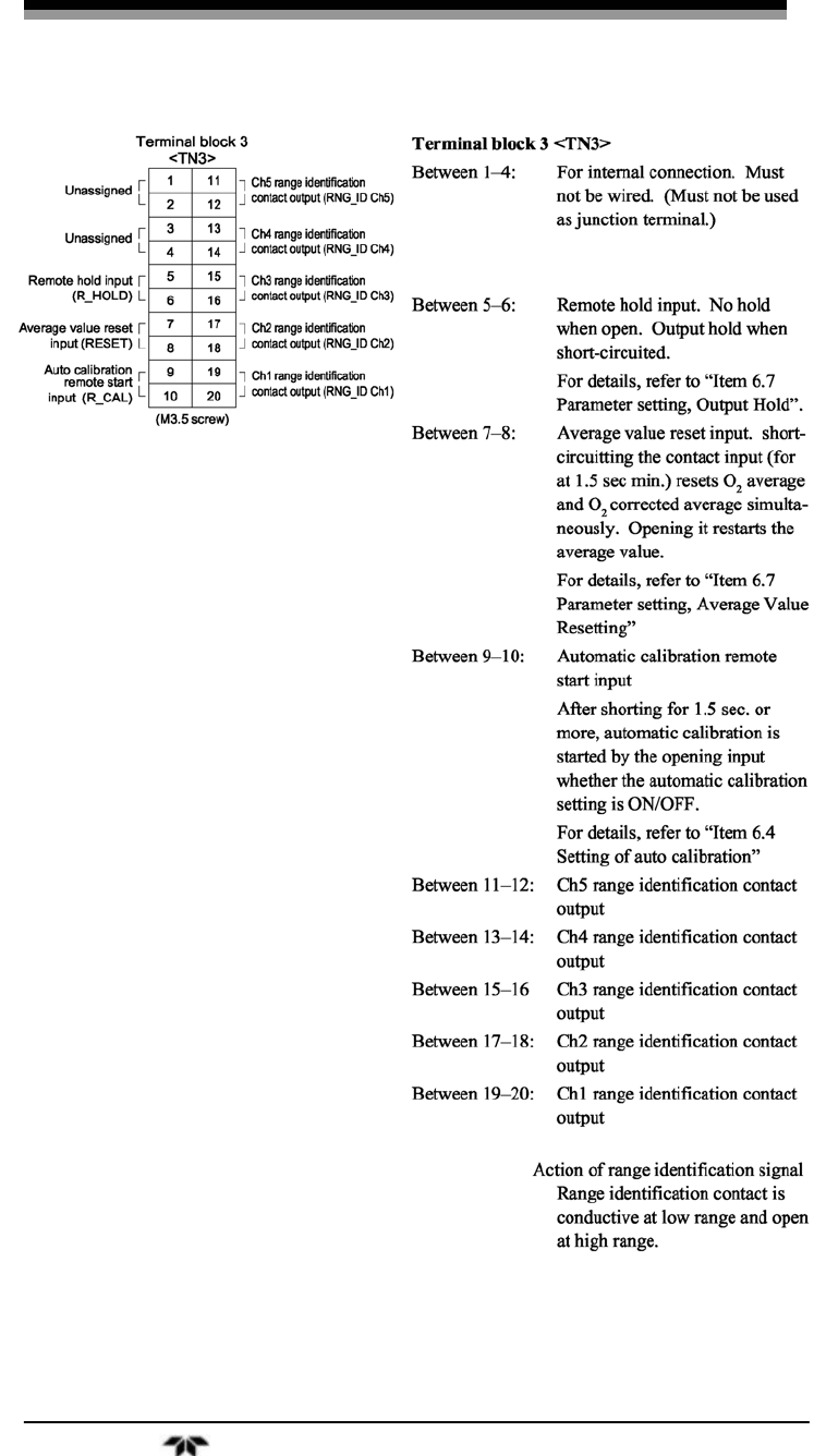
Infrared Gas Analyzer Appendix
Teledyne Analytical Instruments 121

Appendix Model 7600
Teledyne Analytical Instruments 122
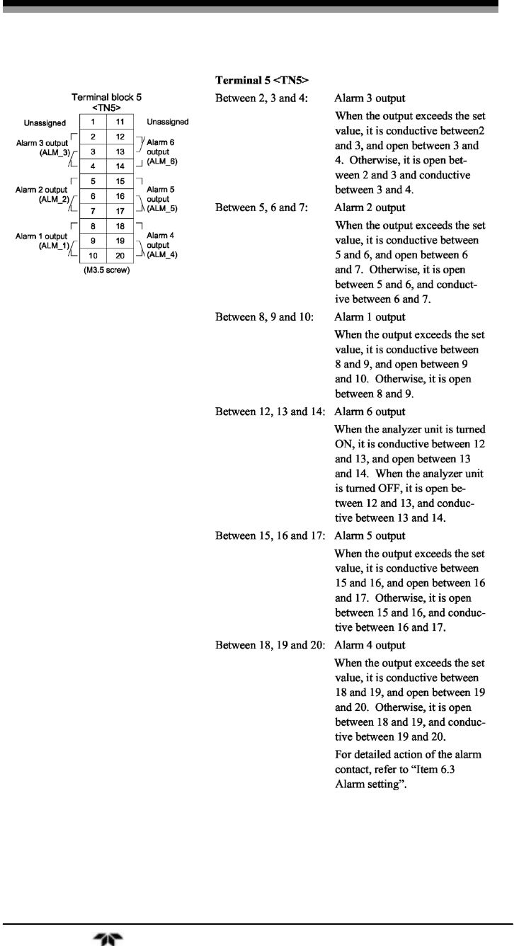
Infrared Gas Analyzer Appendix
Teledyne Analytical Instruments 123

Appendix Model 7600
Teledyne Analytical Instruments 124

Infrared Gas Analyzer Index
Teledyne Analytical Instruments 125
Index
caution sign, iv
combustible gas warning, xi
copyright, ii
figures listing, ix
instasllation checklist, 33
leak check, 33
manuals, additional, v
safety information, iv
serial number, iii
tables listing, x
technician symbol, iv
warning sign, iv
warranty, ii
website address, v

Index Model 7600
Teledyne Analytical Instruments 126
