Telematics Wireless FP200INT Dual Frequency T-Seal User Manual Default Normal
Telematics Wireless Ltd. Dual Frequency T-Seal Default Normal
Users Manual Revised

REV. ∆ DESCRIPTION E.C.N. DATE DRAWN CHECKED
A 086 22/01/05
B According to FCC remarks
C FCC remarks 5/02/2005
PROPRIETARY INFORMATION
ALL RIGHTS RESERVD, NO PARTS OF THIS DOCUMENT MAY BE REPRODUCED, STORD IN
RETRIEVAL SYSTEM, OR TRANSMITTED IN ANY FORM OR BY ANY MEANS, ELECTRONIC,
MECHANICAL PHOTOCOPYING, RECORDING OR OTHERWISE WITHOUT THE PRIOR WRITTEN
PERMISSION OF TELEMATICS WIRELESS LTD. NOR USED IN WHOLE OR IN PART FOR ANY
PURPOSE OR FOR ANY CUSTOMER EXCEPT TELEMATICS WIRELESS.
DESIGNED G.F.K. 22-Jan-2005 SHEET/OF
CHECKED M.N. 23-Dec-2004
APPROVED A.S. 23-Dec-2004
NAME:
TDMA SEAL-FP200 INT
User Manual Q.A. A.S. 23-Dec-2004
1
10
PROD/PROJ: TSEAL
2
1
4
0
7
2
0
1
7
0
0
0
SIZE
A

Note:
This device complies with Part 15 of the FCC Rules.
Operation is subject to the following two conditions:
1) This device may not cause harmful interference, and
2) This device must accept any interference received, including interference that
may cause undesired operation.
WARNING! Changes or modifications to this unit not expressly approved by Telematics
Wireless Ltd. could void the user's authority to operate the equipment.
The digital portion of the transceiver has been tested and found to comply with the limits for a
Class B digital device, pursuant to part 15 of the FCC Rules. These limits are designed to
provide reasonable protection against harmful interference in a residential installation. This
equipment generates, uses and can radiate radio frequency energy and, if not installed and used
in accordance with the instructions, may cause harmful interference to radio communications.
However, there is no guarantee that interference will not occur in a particular installation. If this
equipment does cause harmful interference to radio or television reception, which can be
determined by turning the equipment off and on, the user is encouraged to try to correct the
interference by the following measure:
-Increase the separation between the equipment and receiver.
The antenna is soldered on the circuit board and is an integral part of the unit.
The equipment complies with FCC radiation exposure limits set forth for an uncontrolled
environment.
2140-72017-00-0A REV: C Page 2 Of 10

FP200INT User Manual
Table Of Contents
1. GENERAL INFORMATION ............................................................................. 4
1.1 INTRODUCTION........................................................................................................... 4
1.2 PURPOSE..................................................................................................................... 4
1.3 PREPARATION............................................................................................................. 4
2. INSTALLATION PROCEDURE....................................................................... 4
2.1 PREPARE THE T-SEAL INT .......................................................................................... 4
2.2 ATTACHED THE T-SEAL INT AND MAGNET ON CONTAINER DOORS ......................... 7
2.3 ACTIVATE T-SEAL INT ............................................................................................... 8
2.4 E-MAIL THE T-SEAL INT STATUS............................................................................... 9
3. MONITOR T-SEAL INT STATUS.................................................................. 10
3.1 MONITOR T-SEAL INT STATUS USING HANDHELD READER.................................... 10
3.2 MONITOR T-SEAL INT STATUS USING TDMA READER .......................................... 10
2140-72017-00-0A REV: C Page 3 Of 10

FP200INT User Manual
1. General Information
1.1 Introduction
The T-SEAL int is a TDMA seal, based on AVI transponder with enhanced functions. The
T-Seal int is compatible to currently installed TDMA reader in variety of projects, such as
WIM and border crossing. Additionally, Telematics-Wireless provides handheld reader for
T-Seal int information access and setting.
Note: Everywhere 2.4 GHz is mentioned, the actual real frequency is 2.44 GHz.
1.2 Purpose
The purpose of this document is to provide detail instruction for installing, activating and
monitoring an T-Seal int.
The installation procedure is performed with the FP-200HH handheld reader at the working
frequency of 2.4 GHz.
Note that the T-Seal int is a slave device that communicates with the requester, handheld
reader (2.4 GHz) or way-side reader (915 MHz), according to the requester frequency.
1.3 Preparation
Before installing an T-Seal int in a container, make sure you have the following:
1. 1 x TDMA Seal: T-Seal int with 3M Dual Lock™ strip.
2. 1 x Sensor magnet with 3M Dual Lock™ strip.
3. 2 x 3M Dual Lock™ strips for container doors.
4. 1 x Bag with surface cleaner for 3M Dual Lock™ strip.
2. INSTALLATION PROCEDURE
2.1 Prepare the T-Seal int
The 1st phase is to verify that the T-Seal int is ready without any history saved in it.
2140-72017-00-0A REV: C Page 4 Of 10
FP200INT User Manual
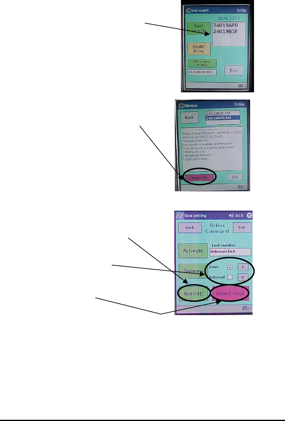
Step 1: Turn on the HH reader
Step 2: “Search” for the T-Seal int and verify
correct T-Seal int ID
Step 3: Go to file and delete old status file for
that T-Seal int
Step 4: Select the T-Seal int and go to Setting
Step 5: Set the T-Seal int time (make sure the
HH reader time is set to GMT)
Step 6: Set the sensor:
Door enabled (√) and C
External disabled and O
And click Sensors
Step 7: Reset the T-Seal int
2140-72017-00-0A REV: C Page 5 Of 10
FP200INT User Manual
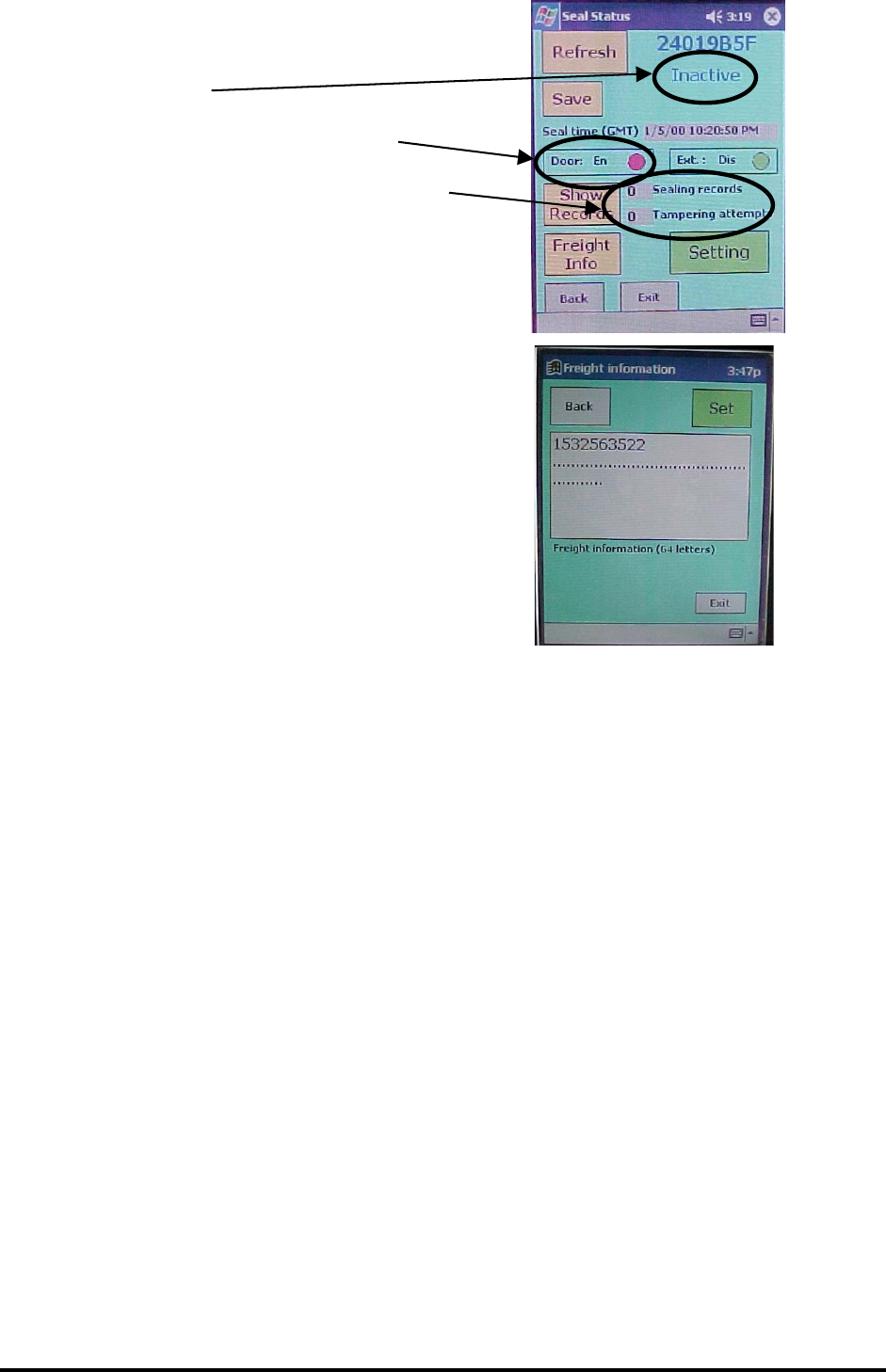
Step 8: Verify T-Seal int is ready:
Inactive
Door sensor enabled and tampered
(RED)
No sealing and tampering records
Step 7: If applicable, Set the Freight Information
The T-Seal int in now ready for installation
2140-72017-00-0A REV: C Page 6 Of 10
FP200INT User Manual
2.2 Attached the T-Seal int and Magnet on Container Doors
The 2nd phase is installing the T-Seal int and the sensor’s magnet in the container.
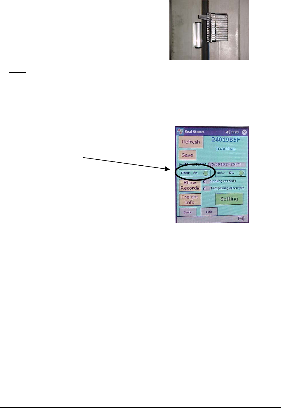
Step 1: Attach the T-Seal int’s on the container right
door (looking from inside) 5 inches from the
door top and as close as possible to the door
edge.
Step 2: Attach the magnet on the other door 7 inches
from the door top and as close as possible to
the door edge.
Note: All surfaces must be clean and dry prior to
3M Dual Lock™ tape application.
The T-Seal int antenna (“finger”) shall be
aligned with the rubber seal of the container
door.
The magnet shall be below the T-Seal int
antenna.
Step 3: Close the doors and “Search” for the
T-Seal int using the HH reader, select it and
verify that the door sensor is enabled and
secure (GREEN)
If the door sensor is still tampered (RED) then open
the container doors and verify the T-Seal int and
magnet are in the right position.
2140-72017-00-0A REV: C Page 7 Of 10
FP200INT User Manual
2.3 Activate T-Seal int
The 3rd phase is activating the T-Seal int.
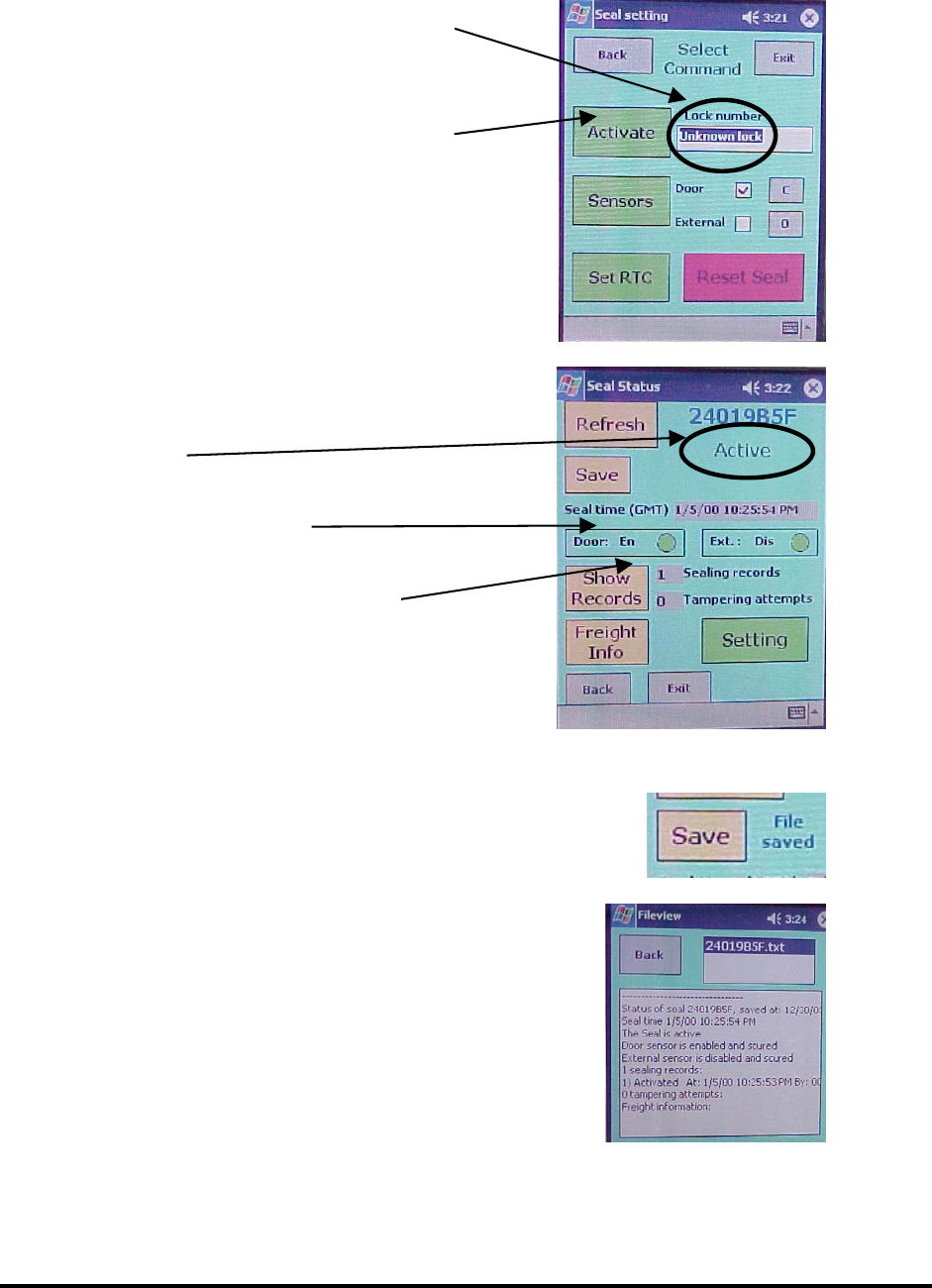
Step 1: “Search” for the T-Seal int using the HH reader, select it and verify that
the door sensor is enabled and secure.
Step 2: Go to Setting and enter the lock number
Step 3: Click Activate. The HH reader will
return to the status screen
Step 4: Verify that the T-Seal int is:
Active
Door sensor secured
Number of sealing records = 1
Step 5: If T-Seal int status didn’t changed then repeat step 3 and 4
Step 6: Click Save to save the T-Seal int status
into file
Step 7: Go to File View screen and verify
T-Seal int status is updated
The T-Seal int is now active
2140-72017-00-0A REV: C Page 8 Of 10

FP200INT User Manual
2.4 E-Mail the T-Seal int Status
The 4th phase is getting the T-Seal int status file from the HH Reader
Step 1: Delete/Move old T-Seal int status files
from your PC
Step 2: Connect the HH reader to PC
Step 3: Activate the Microsoft ActiveSync
Step 4: The T-Seal int status will be updated in
the ActiveSync directory on your PC
2140-72017-00-0A REV: C Page 9 Of 10
FP200INT User Manual
2140-72017-00-0A REV: C Page 10 Of 10
3. MONITOR T-SEAL INT STATUS
3.1 Monitor T-Seal int Status Using Handheld Reader
See HH reader user manual.pdf
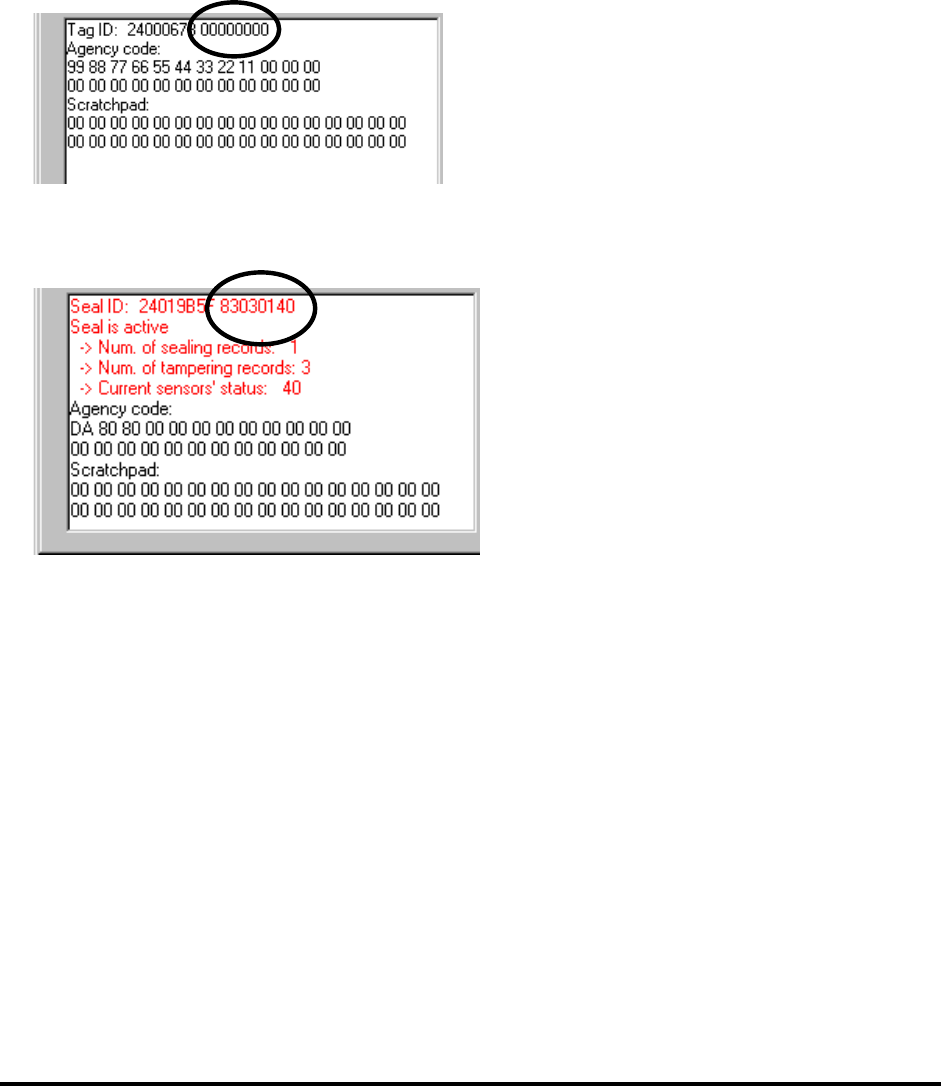
3.2 Monitor T-Seal int Status Using TDMA Reader
A standard TDMA reader can get the T-Seal int status by performing read internal memory
command.
In standard AVI transponder the 4 bytes followed the transponder ID are 0.
In the T-Seal int this field is used to report the T-Seal int status
Where:
Byte 0: D7 - T-Seal int flag, D1 – Tampered, D0 – Activated
Byte 1: Number of tampering records
Byte 2: Number of sealing records
Byte 3: Sensors’ current status (bit-wise, 1 = tampered)