Telematics Wireless FP300RA Non-multilateration FP-300RA ASTM Reader User Manual FP 300RA Usrman
Telematics Wireless Ltd. Non-multilateration FP-300RA ASTM Reader FP 300RA Usrman
Users Manual Revised

PROPRIETARY INFORMATION
ALL RIGHTS RESERVD, NO PARTS OF THIS DOCUMENT MAY BE REPRODUCED, STORD IN
RETRIEVAL SYSTEM, OR TRANSMITTED IN ANY FORM OR BY ANY MEANS, ELECTRONIC,
MECHANICAL PHOTOCOPYING, RECORDING OR OTHERWISE WITHOUT THE PRIOR WRITTEN
PERMISSION OF TELEMATICS WIRELESS LTD. NOR USED IN WHOLE OR IN PART FOR ANY
PURPOSE OR FOR ANY CUSTOMER EXCEPT TELEMATICS WIRELESS.
DESIGNED G.F.K. 11-Aug-2005 SHEET/OF
CHECKED M.N. 11-Aug-2005
APPROVED A.S. 11-Aug-2005
NAME:
ASTM READER –FP-300RA
User Manual
Q.A. A.S. 11-Aug-2005
1
38
PROD/PROJ: ASTM Reade
r
214072018 0 0 0
SIZE
A
REV. ∆ DESCRIPTION E.C.N. DATE DRAWN CHECKED
A

2140-72018-00-0A REV: A Page 2 Of 38
Note:
This device complies with Part 15 of the FCC Rules.
Operation is subject to the following two conditions:
1) This device may not cause harmful interference, and
2) This device must accept any interference received, including interference that may
cause undesired operation.
WARNING! Changes or modifications to this unit not expressly approved by Telematics
Wireless Ltd. could void the user's authority to operate the equipment.
The digital portion of the transceiver has been tested and found to comply with the limits for a
Class B digital device, pursuant to part 15 of the FCC Rules. These limits are designed to provide
reasonable protection against harmful interference in a residential installation. This equipment
generates, uses and can radiate radio frequency energy and, if not installed and used in accordance
with the instructions, may cause harmful interference to radio communications. However, there is
no guarantee that interference will not occur in a particular installation. If this equipment does
cause harmful interference to radio or television reception, which can be determined by turning the
equipment off and on, the user is encouraged to try to correct the interference by the following
measure:
-Increase the separation between the equipment and receiver.
The antenna and therefore the unit, used for this transmitter must be installed to normally provide
minimum separation distance of at least 2 meters from all persons and must not be co-located or
operating in conjunction with any other antenna or transmitter.
The Reader is sold with power cable with molded ferrite that provide common-mode filtering.
Recommended ferrite manufacturer: Fair-Rite, part number: 0444164281.
The communication cables shall be installed by professional installer, placing ferrites on the cables
that are supplied with unit.
Recommended ferrite manufacturer: Fair-Rite, part number: 0444164281.

FP300RA User Manual
2140-72018-00-0A REV: A Page 3 Of 38
Table Of Contents
CHAPTER 1: INTRODUCTION ..........................................................................................5
1.1 SCOPE......................................................................................................................................5
1.2 GENERAL DESCRIPTION ..........................................................................................................6
1.2.1 Purpose and Use..............................................................................................................6
1.2.2 Main Technical Characteristics.......................................................................................7
1.2.3 Maintenance Utility ........................................................................................................7
1.2.4 Additional Equipment Needed........................................................................................7
1.3 PHYSICAL DESCRIPTION .........................................................................................................8
1.4 FUNCTIONAL DESCRIPTION.....................................................................................................9
1.4.1 Normal Mode..................................................................................................................9
1.4.1.1 Normal Mode Functions .............................................................................................9
1.4.1.2 Transponder Access Capabilities................................................................................9
1.4.1.3 Air Interface................................................................................................................9
1.4.1.4 Multilane Support .....................................................................................................10
1.4.1.5 Lane Discrimination Support....................................................................................11
1.4.1.6 Support for Reader Synchronization.........................................................................11
1.4.1.7 Active List.................................................................................................................11
1.4.1.8 Hot Lists....................................................................................................................12
1.4.2 Maintenance Mode .......................................................................................................12
1.4.2.1 Configuration ............................................................................................................12
1.4.2.2 Communication Zone Calibration.............................................................................12
1.4.2.3 Self-Test....................................................................................................................12
1.4.3 Host Communication ....................................................................................................13
1.4.4 Real-Time Clock...........................................................................................................13
CHAPTER 2: INSTALLATION..........................................................................................14
2.1 GENERAL...............................................................................................................................14
2.2 INSTALLATION REQUIREMENTS ............................................................................................14
2.2.1 Integration in Systems...................................................................................................14
2.2.2 Safety Considerations ...................................................................................................15
2.2.3 Mechanical Data ...........................................................................................................15
2.3 INSTALLATION GUIDELINES..................................................................................................16
2.3.1 Power Requirements .....................................................................................................16
2.3.2 Antennas .......................................................................................................................16
2.3.2.1 Antenna Mounting Position Requirements...............................................................17
2.3.2.2 FP-300RA-to-Antenna Cabling ................................................................................17
2.3.3 Communication Cables.................................................................................................17
2.3.4 Grounding and Lightning Protection Requirements .....................................................18
2.4 INSTALLATION PROCEDURE..................................................................................................18
2.4.1 Tools and Materials.......................................................................................................18
2.4.2 Preparation for Installation ...........................................................................................18
2.4.3 FP-300RA Installation Procedure .................................................................................18
2.4.3.1 Physical Installation..................................................................................................18
2.4.3.2 Cable Connections ....................................................................................................19
2.4.3.3 Final Inspection.........................................................................................................19
CHAPTER 3: OPERATION ................................................................................................20
3.1 SCOPE....................................................................................................................................20
3.2 POWER-UP.............................................................................................................................20
3.3 FP-300RA CONFIGURATION .................................................................................................21
3.3.1 Setting Host Interface Parameters.................................................................................21
3.3.2 Setting Initial Tx Mode.................................................................................................21
3.3.3 Setting TDMA Mode ....................................................................................................22

FP300RA User Manual
2140-72018-00-0A REV: A Page 4 Of 38
3.3.4 Setting Transponder Access Parameters.......................................................................22
3.3.5 Setting Burst Mode .......................................................................................................22
3.3.6 Setting SYNC Mode .....................................................................................................22
3.3.7 Setting Multilane Mode ................................................................................................23
3.3.8 Setting Lane Discrimination .........................................................................................23
3.3.9 Setting Digital I/O.........................................................................................................24
3.3.10 Save Current Settings....................................................................................................24
3.4 HOT LIST CONFIGURATION ...................................................................................................24
3.4.1 Get Hot List Status........................................................................................................24
3.4.2 Remove Hot List...........................................................................................................24
3.4.3 Add New Hot List.........................................................................................................24
3.4.4 Set Hot List Auto Function...........................................................................................25
3.4.5 Add Transponder to Hot List ........................................................................................25
3.4.6 Remove Transponder from Hot List .............................................................................25
3.4.7 Saving the Hot List .......................................................................................................25
APPENDIX A: CONNECTION DATA ..............................................................................26
A-1 ANTENNA CONNECTORS .......................................................................................................26
A-2 POWER INPUT CONNECTOR...................................................................................................26
A-3 DIGITAL INTERFACE CONNECTOR ........................................................................................26
A-4 HOST INTERFACE CONNECTOR .............................................................................................27
A-5 MAINTENANCE INTERFACE CONNECTOR..............................................................................28
A-6 AUXILIARY INTERFACE CONNECTOR ...................................................................................28
APPENDIX B: MAINTENANCE UTILITY......................................................................30
B-1. SCOPE....................................................................................................................................30
B-2. INSTALLATION ......................................................................................................................30
B-2.1 Hardware and Software Requirements .........................................................................30
B-2.2 Installation Procedure ...................................................................................................30
B-2.3 Preliminary Configuration ............................................................................................30
B-3. MAIN WINDOW .....................................................................................................................31
B-3.1 Monitor Area.................................................................................................................31
B-3.2 Active List Area............................................................................................................31
B-3.3 Log File.........................................................................................................................32
B-3.4 Sending Periodic Status Request ..................................................................................32
B-3.5 Setting the Communication Mode ................................................................................32
B-3.6 Setting/Resetting the Digital Output Port .....................................................................32
B-3.7 Information Fields.........................................................................................................32
B-3.8 Requests Area ...............................................................................................................33
B-3.9 Setting Area ..................................................................................................................33
B-4. FILE MENU ............................................................................................................................34
B-5. FP-300RA CONFIGURATION WINDOW .................................................................................35
B-6. HOT LIST ...............................................................................................................................36
B-6.1 Auto-Function...............................................................................................................36
B-7. RF SETTING WINDOW ...........................................................................................................37
B-7.1 Get Button.....................................................................................................................37
B-7.2 Set Default Button ........................................................................................................37
B-7.3 Tx Mode........................................................................................................................37
B-7.4 Transmitter....................................................................................................................38
B-7.5 Receiver ........................................................................................................................38
B-7.6 Vector Modulator..........................................................................................................38
B-7.7 Calibration Process .......................................................................................................38

FP300RA User Manual
2140-72018-00-0A REV: A Page 5 Of 38
Chapter 1: Introduction
1.1 Scope
This manual covers the characteristics, applications, installation, configuration and maintenance of
the FP-300RA reader, an advanced and flexible roadside component offered by Telematics
Wireless for use in electronic Automatic Vehicle Identification (AVI) systems.
The information included in this manual is organized as follows:
Presents the manual scope and organization, and describes the
FP-300RA reader functions and capabilities.
Chapter 1 – Introduction
Provides the information needed to plan the FP-300RA
installation, and detailed installation instructions.
Chapter 2 – Installation
Provides information on the FP-300RA operating modes.
Chapter 3 – Operation
Presents the information needed to connect to the FP-300RA.
Appendix A –
Connection Data
Presents the functions of the FP-300RA maintenance utility,
instructions for its installation on a PC, and covers its utilization
for configuration and calibration of FP-300RA units.
Appendix B –
Maintenance Utility
For additional information on the FP-300RA technical specifications, its systems integration, help
in interfacing to the FP-300RA, and other issues regarding utilization of FP-300RA advanced
characteristics, contact Telematics Wireless.
FP300RA User Manual
2140-72018-00-0A REV: A Page 6 Of 38
1.2 General Description
1.2.1 Purpose and Use
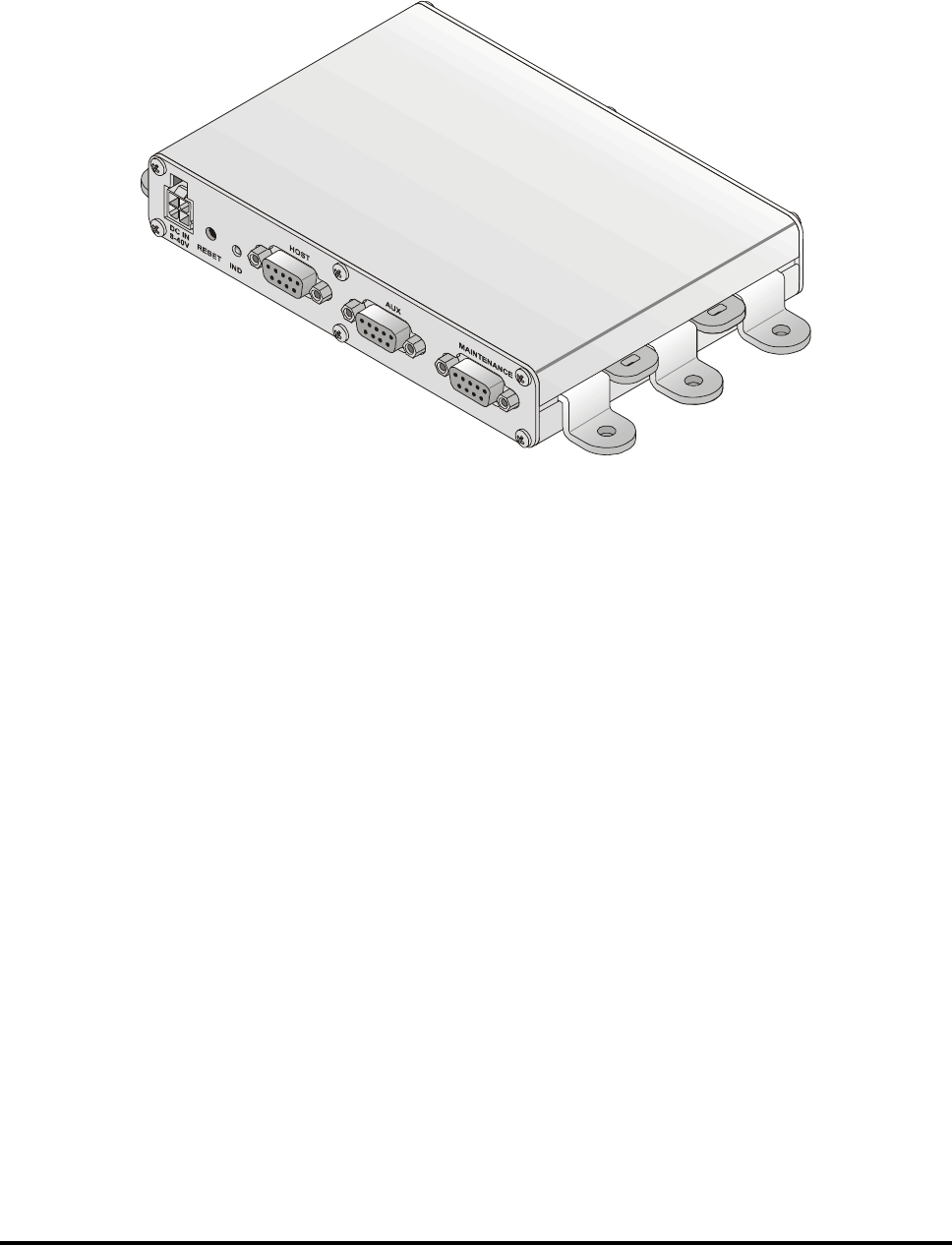
The FP-300RA reader offered by Telematics Wireless is a versatile, compact and reliable unit
that serves as the roadside component of a vehicle identification system. Figure 1-1 shows a
general view of the FP-300RA.
Figure 1-1: FP-300RA, General View
The FP-300RA can automatically identify passing transponders; depending on the system
operator’s requirements and the specific activities configured by the operator, the FP-300RA
can also retrieve information from the transponder, write information to the transponder and
instruct it to alert the driver by audio or visual means (beeps, red/yellow/green indicators, etc.).
Multiple digital inputs and outputs can be used to read the status of external sensors, and
activate various devices. An auxiliary interface can be used as an additional serial
communication port to further extend system capabilities and versatility; this port can also be
used for synchronizing multiple FP-300RA.
The FP-300RA activities are transmitted on-line to host computers. The FP-300RA
communicates with the host computer via a programmable serial interface that provides full
control over the FP-300RA operation, and enables collecting extensive vehicle-related data. A
local maintenance port can be used to configure and maintain the FP-300RA, independently of
the communication with the host computer. These ports also provide control over the digital
I/O and auxiliary port.
The FP-300RA can be used in a wide range of applications, for example, electronic toll
collection systems, border crossing, access control, Weigh In Motion (WIM) stations,
electronic seal systems, vehicle-related services such as parking and gas station payment, and
many other applications.
The FP-300RA may be operated from DC sources in the range of 8 to 30 VDC, including
batteries. It has low power drain (less than 5 W) and very compact size.

FP300RA User Manual
2140-72018-00-0A REV: A Page 7 Of 38
1.2.2 Main Technical Characteristics
The FP-300RA is a complete user-configurable RF and data processing unit that supports two-
way communications with in-vehicle transponders (“tags”) using the ASTM V6 Slotted-Aloha
Time Division Multiple Access (TDMA) protocol. The physical layer is compatible with
ASTM PS111-98.
The FP-300RA communicates with transponders that enter its communication zone at speeds
of up to 125 mph (200 kph). The communication uses the 902 to 928 MHz ISM band, with
software-configurable synthesized transmit frequency; the data rate is 500 kbps, with ASK
modulation. A fixed receiver frequency within the ISM band is used (915 MHz default).
The FP-300RA can use many types of antennas, to match the spatial resolution needed in the
desired operation mode (single lane or multilane). It has an integrated antenna-switching unit
for multilane sites, supporting up to 4 lanes. The FP-300RA antenna switching rate is
configurable; when switching to a lane, the FP-300RA also automatically switches to the RF
parameters selected for that lane during the site calibration process.
The high transmit power (software-controllable up to 31.2 dBm) and the high selectivity, high-
sensitivity receiver with software-controllable squelch level ensure reliable communication and
high performance with minimal external support.
1.2.3 Maintenance Utility
Telematics Wireless offers a dedicated reader maintenance utility for the FP-300RA, that can
be installed on any PC running Microsoft® Corp. Windows 2000, Xp. The FP-300RA
connects to one of the free serial communication ports of the PC using a null modem cable.
The maintenance utility provides full control over FP-300RA RF and data processing
parameters, enables monitoring its operation and updating the FP-300RA software.
1.2.4 Additional Equipment Needed
The only additional accessories that have to be provided are:
Antennas for the specific installation requirements, with the required coaxial cables
for connection to the reader.
The number of antennas required and their radiation pattern depend on the
application mode:
• Single-lane mode: single transmit/receive antenna.
• Multilane mode: one antenna per active lane, with the option to add one
separate transmit antenna.
DC source capable of providing the required supply voltage (8 to 30 VDC) at
maximum 5 W.
Means for communicating with the host (serial asynchronous communication link).
FP300RA User Manual
2140-72018-00-0A REV: A Page 8 Of 38
1.3 Physical Description
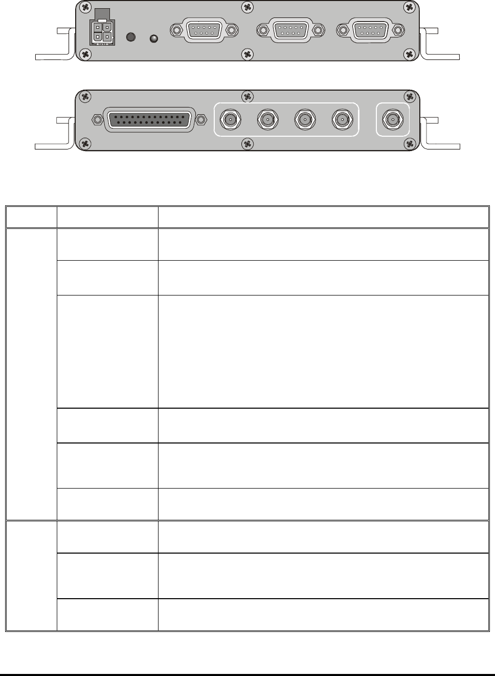
Figure 1-2 and Figure 1-3 show the components located on the FP-300RA (see Figure 1 for
orientation). The functions of the various components are described in Table 1-1.
DC IN
8-30V
AUXHOST MAINTENANCE
RESET IND
Figure 1-2: FP-300RA, Host Side Panel
4 3 2 1
I/O
MULTILANE ANT ANT
MAIN
Figure 1-3: FP-300RA, Antenna Side Panel
Table 1-1: Controls
Side Item Function
DC IN Connector 4-pin connector used to connect the DC input voltage, and enable
external resetting by dry-contact closure to ground.
RESET Push-
button
Internal push-button used to initiate cold restart of the FP-300RA.
IND Indicator Status indicator, provides the following indications:
1. Flashing in green: normal operation, no tags detected
Flashing in orange: normal operation, tags detected
Fast flashing in red: mute mode (transmission disabled)
Steady red: FP-300RA malfunction detected
Alternating off-orange-green sequence: software downloading
in progress
HOST Connector 9-pin D-type female connector includes a serial asynchronous RS-
232 DTE interface used for connection to the host computer.
AUX Connector 9-pin D-type female connector, includes a serial asynchronous RS-
232 DTE interface used for connection to auxiliary devices, or as
synchronization pulse input or output.
Host
MAINTENANCE
Connector
9-pin D-type female connector, includes a serial asynchronous RS-
232 DTE interface used for maintenance.
I/O Connector 25-pin D-type female connector, used to connect to the digital I/O
interface.
MULTILANE
ANT 1, 2, 3, 4
Connectors
SMA connectors for connection to the secondary antennas.
Antenna
MAIN ANT
Connector
SMA connector for connection to the main antenna.

FP300RA User Manual
2140-72018-00-0A REV: A Page 9 Of 38
1.4 Functional Description
The FP-300RA has two operating modes:
Normal mode
Maintenance mode.
1.4.1 Normal Mode
1.4.1.1 Normal Mode Functions
The functions performed by the FP-300RA during operation in the normal mode are as
follows:
• Provide communication with transponders passing through its communication zone,
using the configured mode (either single lane or multilane)
• Support lane discrimination functionality.
• Maintain a list of the transponders that are currently detected within the FP-300RA
communication zone (active list)
• Perform preassigned functions (called auto-functions) on transponders detected to
enter the communication zone (hot list)
• Perform various functions on transponders in response to host requests
• Send event and status reports to the host.
1.4.1.2 Transponder Access Capabilities
The FP-300RA can access transponders with the following commands:
• Read/write transponder internal or external memory
• Operate transponder driver interface
• Send transponder to sleep mode, with or without driver alert
• Write time stamp into the transponder memory.
1.4.1.3 Air Interface
The air interface is based on ASTM V6 protocol. The FP-300RA performs the following
tasks:
• Send frame control messages according to the selected mode (open-road or lane-
based timing).
• Receive activation messages from transponders.
• Detect and report new transponders that entered the communication zone.
• Send and receive data to/from transponders and report the results to the requesting
entity.
FP300RA User Manual
2140-72018-00-0A REV: A Page 10 Of 38
1.4.1.4 Multilane Support
The FP-300RA has five antenna connectors: one serves for connection to the main antenna,
and four additional connectors serve for connection to secondary antennas.
The FP-300RA can transmit and receive using any one of the antenna connectors; the
selection of transmit and receive antennas is made every TDMA frame.
Table 1-2 lists the antenna configurations used for single lane and multilane operation.
Table 1-2: Antenna Configurations
Operation Mode Tx Antenna Rx Antenna
Single lane mode Main antenna Main antenna
Multilane mode with one Tx
communication zone
Main antenna Secondary antenna according
to multilane setup
Multilane mode with separate
lane Tx and Rx communication
zones
Secondary antenna
according to the multilane
setup
Secondary antenna according
to the multilane setup
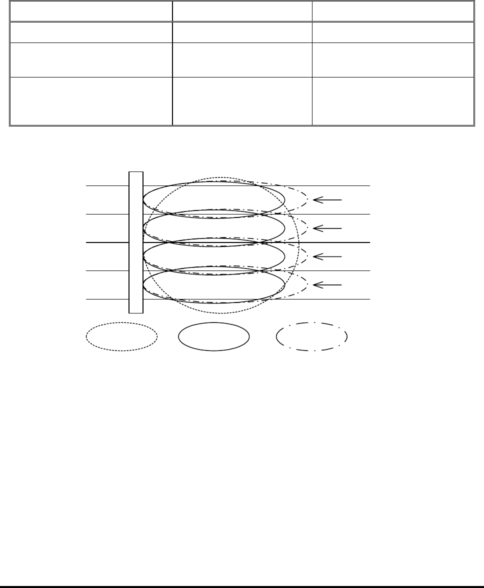
Figure 1-4 shows typical multilane site communication zones.
Lane 1
Lane 2
Lane 3
Lane 4
GANTRY
Rx zone
Single Tx
zone Lane Tx zone
Figure 1-4: Identification of Antenna Used in the Various Operation Modes
The multilane parameters that can be configured include:
• Number of active lanes
• Switching time, i.e., number of frames per lane.
The FP-300RA enables calibrating the communication zone of every lane independently.

FP300RA User Manual
2140-72018-00-0A REV: A Page 11 Of 38
1.4.1.5 Lane Discrimination Support
The FP-300RA lane discrimination function enables detecting on which lane the transponder
entered the communication zone.
The lane discrimination parameters that can be configured include:
• Detection of lane in which a transponder enters or leaves the communication zone
• Search window size
• Minimum number of activation messages that must be received
• Minimum delta (difference between the numbers of activation messages received in
each lane) needed to identify the lane.
1.4.1.6 Support for Reader Synchronization
The FP-300RA supports the master-slave synchronization mode:
• When configured as synchronization master, the FP-300RA outputs
synchronization pulses via its AUX port, at RS-232/422 levels.
• When configured as slave, the FP-300RA synchronizes its air interface to the
synchronization pulses received via its AUX port, at RS-232/422 levels.
While operating in the slave mode, the FP-300RA sends messages reporting loss and regaining
of synchronization through the host and maintenance interfaces.
1.4.1.7 Active List
The FP-300RA maintains a list of transponders that are currently in the FP-300RA
communication zone: this list is the active list, and can include up to 100 transponders. The
FP-300RA will send the active list to the host upon host’s request.
The criteria for adding transponders to the active list are:
• New activation message has been received
• A successful data access is performed with a transponder that is not in the list.
The FP-300RA can check if any transponder is still within its communication zone by self-
initiated data access (ping). Ping reads the transponder internal memory contents. The time
between consecutive pings can be set by commands, or pinging can be disabled altogether.
The criteria for removing a transponder from the active list are:
The transponder failed to respond to an FP-300RA command (auto-function, ping or
host request)
If the ping function is disabled, then:
If the transponder has not been accessed, i.e., it is in the out-of-link state, it
will be removed after a configurable number of frames from the last received
activation message
If the transponder has been accessed, i.e., it is in the link-granted state, it will
be removed 10 seconds after the last access.

FP300RA User Manual
2140-72018-00-0A REV: A Page 12 Of 38
1.4.1.8 Hot Lists
The FP-300RA supports up to 20 hot lists with a total of 1024 transponders:
2. A hot list consists of an automatically-performed function (auto-function), a
digital output command and a list of transponders.
3. A transponder can be included in only one hot list.
4. Hot list 0 is the default hot list and contains no transponders.
When a transponder enters the communication zone, the FP-300RA checks whether it is a
member of a predefined hot list: if positive, the corresponding hot list auto-function and digital
output command are performed.
1.4.2 Maintenance Mode
The tasks performed in the maintenance mode are as follows:
Configuration
Communication zone calibration
Self-test.
1.4.2.1 Configuration
The FP-300RA configurable parameters are divided into two groups:
Parameters that can be changed only via the maintenance interface
Parameters that can be changed via either the host or the maintenance interface.
The current configuration is stored in non-volatile memory. When the FP-300RA is restarted, it
looks for the last saved configuration and uses it.
If no valid configuration is found, the FP-300RA sets the configuration parameters to their
default values. The configurable parameters are explained in Appendix C.
1.4.2.2 Communication Zone Calibration
The FP-300RA has built-in transmit power and digital squelch control. The FP-300RA stores
the transmit power and digital squelch settings for every active lane and use it when switching
between lanes. The calibration procedure (explained in Appendix E), enables setting every
lane’s communication zone.
1.4.2.3 Self-Test
The FP-300RA supports two types of tests, destructive and non-destructive. Non-destructive
test enables the FP-300RA to continue operating in normal mode, whereas the destructive test
terminates the normal mode.

FP300RA User Manual
2140-72018-00-0A REV: A Page 13 Of 38
1.4.3 Host Communication
The FP-300RA supports communication with a host. Two types of messages are used:
FP-300RA-initiated message used to report events, e.g., a new transponder
Messages sent in response to host requests.
The message set is presented in Appendix D.
1.4.4 Real-Time Clock
The FP-300RA has an internal real time clock (RTC) with a resolution of 10 millisecond.
Whenever the FP-300RA is restarted, the RTC starts running from an initial value of 00:00
January 1, 2000. Therefore, the host must make the translation to “normal” time.
The FP-300RA RTC can be set via the host and/or maintenance interface.
FP300RA User Manual
2140-72018-00-0A REV: A Page 14 Of 38
Chapter 2: Installation
2.1 General
This Chapter provides the information needed to install FP-300RA readers.
The information presented in this Chapter is organized as follows:
• Installation requirements – Section 2.2.
• Installation guidelines – Section 2.3.
• Installation procedures – Section 2.4.
Before starting the installation procedures, make sure to review the Safety Information
section at the beginning of this manual.
2.2 Installation Requirements
2.2.1 Integration in Systems
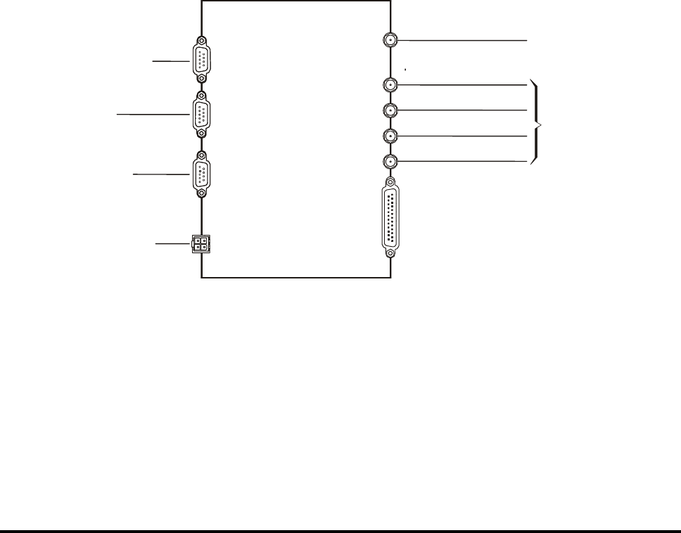
Figure 2-1 shows the connections needed to integrate an FP-300RA unit in a typical electronic
vehicle identification system. Use the information appearing in Chapter 1 and Appendix A,
that covers the FP-300RA interface characteristics and connection data, to prepare cables in
accordance with the specific requirements of each location.
1
2
3
4
I/O
MULTILANE ANT
DC IN
AUX
HOST
MAINTENANCE
FP-300RA
To Maintenance PC
To Auxiliary
Devices
To Host Computer
To DC Power Source
(8 - 30V)
To Main
Antenna
To Sensors
& Controlled Devices
MAIN ANT
To Secondary
(Lane) Antennas
Figure 2-1: FP-300RA Connections
FP300RA User Manual
2140-72018-00-0A REV: A Page 15 Of 38
2.2.2 Safety Considerations
In addition to the electrical connections shown in Figura 2-1, the FP-300RA case must be
connected to protective grounding.
Protective devices, complying with the applicable international standards and the national and
local regulations, must be used on all the lines connected to the FP-300RA, to protect against
lightning discharges and accidental contact with high-voltage lines.
Warning
The FP-300RA must be properly grounded whenever cables are
connected to its connectors. To ground the FP-300RA, attach its case
to a high-quality, low resistance protective grounding system, in a
way that ensures good electrical contact.
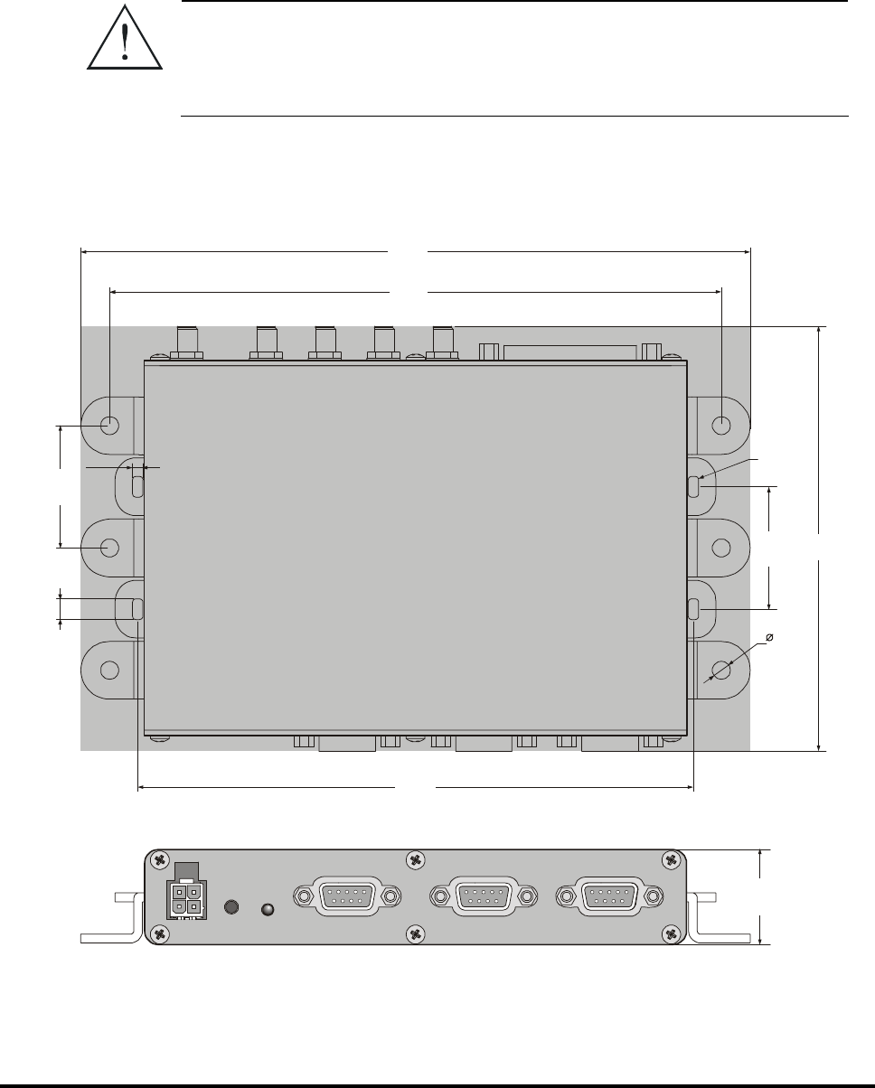
2.2.3 Mechanical Data
Figure 2-2 provides mechanical data for planning the installation of an FP-300RA unit.
27.5
DC IN
8-30V
AUX HOST MAINTENANCE
RESET IND
3
4PL
35.4
4PL
6
4PL
5.2
6PL.
R1
TYP
35.4
2PL
160.8
2PL.
177
3PL.
193.7
123
Figure 2-2: FP-300RA Mechanical Data

FP300RA User Manual
2140-72018-00-0A REV: A Page 16 Of 38
2.3 Installation Guidelines
The FP-300RA is intended for installation in protected cabinets that prevent direct exposure to
sun radiation, rain, dust and dirt. It does not require forced air cooling.
The following sections provide additional information needed for successful utilization of the
FP-300RA.
2.3.1 Power Requirements
The FP-300RA operates on 8 to 30 VDC, and its maximum power drain is 5W. A suitable
power source must be provided as part of the installation.
Separate power supply lines should be routed to each FP-300RA unit.
The FP-300RA does not have an ON/OFF power switch, and will start operating as soon as
power is connected. Therefore, it is recommended to install a circuit breaker, which will also
serve as an ON/OFF switch, to protect the supply line of each FP-300RA.
2.3.2 Antennas
The type of antenna to be used with the FP-300RA is generally determined by the FP-300RA
application and communication zone requirements.
In most installations, two types of antenna are used:
• For wide communication zone applications, a wide beam antenna is
recommended. The antenna can be mounted above the lane or beside the road.
• For narrow communication zones, where lane-to-lane and/or cross-lane
discrimination is required, a narrow beam antenna can be used. This antenna must
be mounted over the center of the lane.
For either type of antenna, the positioning of the antenna must be carefully set to achieve the
required communication zone pattern. For installations subject to external interference, lower
gain antennas can be used.
Contact Telematics Wireless if you need help in selecting suitable antennas.
Note: The antenna (ANT) connectors of the FP-300RA must always be terminated
in matched (50Ω) loads. Connect 50Ω loads with minimal rating of 1W to any
FP-300RA ANT connector not connected to an antenna.
When the installation procedures call for connecting RF cables to the
FP-300RA antenna connectors before the corresponding antennas are
installed, connect the loads at the antenna ends of the cables.

FP300RA User Manual
2140-72018-00-0A REV: A Page 17 Of 38
2.3.2.1 Antenna Mounting Position Requirements
FP-300RA antennas are mounted in accordance with the application requirements and antenna
manufacturer's instructions. Consider the following position requirements:
• Height: for above-the-lane installation, the antennas can be mounted on a gantry,
overpass, or other above-the-lane facility. Each antenna must be mounted at a
sufficient height to meet local vertical clearance requirements.
Any antenna can be damaged and/or misaligned if struck. If snow buildup on vehicles is
possible, mounting height must include clearance for snow buildup for the highest
anticipated vehicle using the lane(s).
• Multilane applications: each antenna should be mounted over the center of its
lane. For lane discrimination, antennas should be mounted over the center of the
highway or group of lanes to be included in the FP-300RA communication zone.
• Beside-the-road installation: the antenna(s) can be pole mounted.
Antennas must be mechanically positioned to provide the appropriate beam orientation for the
communication zone wanted. Suitable arrangements must be provided to permit mechanical
adjustment of antenna direction, to achieve the beam pattern and communication zone wanted.
2.3.2.2 FP-300RA-to-Antenna Cabling
The maximum distance between the FP-300RA and its antenna is limited by cable signal loss.
Generally, the total signal loss between the antenna and the FP-300RA must be less than 3 dB.
Any losses on antenna patch panels or switching matrices must also be taken into
consideration.
For installations where the FP-300RA-to-antenna cable length is less than 125 feet (38 meters),
you may use Times LMR 600/400, Andrew type LD F4-50A 1/2-inch Heliax, or other cables
with similar or better characteristics.
Cable routes should be carefully planned, to ensure they follow the shortest path yet are far
from sources of strong electrical interference such as electrical motors, air conditioning
equipment, two-way radios, etc. Make sure that cables are physically protected, for example,
by routing them within cable ducts: sharp bends, distortion of the cable outer shield, etc., may
increase the attenuation by an unpredictable amount.
2.3.3 Communication Cables
The cables connecting the FP-300RA communication ports (auxiliary, maintenance and in
particular the connection to the host computer) must be shielded. Communication-grade cables
consisting of twisted pairs with external shield should be used, and the shield must be
grounded at one end.
Cables should be run through grounded conduits, to minimize external interference.

FP300RA User Manual
2140-72018-00-0A REV: A Page 18 Of 38
2.3.4 Grounding and Lightning Protection Requirements
All the FP-300RAs, antennas, mounting poles, cabinets, cable conduits and cables must be
properly grounded in accordance with the applicable regulations, to prevent injury to personnel
or damage to equipment from lightning or other high voltage sources.
Ground bonding points must be free of paint and corrosion. Star washers should be placed on
screws to ensure good electrical contact.
For installations where a complete bonded ground connection is not possible for the entire
antenna-to-FP-300RA cabling, a separate lightning arrester must be installed for each antenna
cable at a point near the RF connection to the FP-300RA cabinet.
2.4 Installation Procedure
2.4.1 Tools and Materials
No special tools and materials are required for FP-300RA installation.
2.4.2 Preparation for Installation
Refer to the site installation plan, and make sure all the required components, cables, and
accessories are available.
Identify the prescribed physical location of each system component, and find the grounding
points.
Before installing any item (FP-300RA, cabinet, mounting accessory, antenna, cable conduit,
etc.), thoroughly clean the surface on which it will be mounted.
2.4.3 FP-300RA Installation Procedure
2.4.3.1 Physical Installation
Use the following general procedure to install the FP-300RA in the prescribed location:
1. Identify the exact location and position of the FP-300RA.
2. Mark the 6 holes to be drilled in accordance with the information appearing in
Figure 2-2, and then drill using an appropriate drill tip.
3. Thoroughly clean the surface on which the FP-300RA will be mounted. Make
sure to remove any burrs.
4. Insert a flat washer and a star washer on each of the 6 fastening screws. Prepare
additional flat washers and star washers for insertion under the nuts.
5. Place the FP-300RA on the mounting position, and fasten it with the 6 screws
and nuts.

FP300RA User Manual
2140-72018-00-0A REV: A Page 19 Of 38
2.4.3.2 Cable Connections
Caution
The FP-300RA does not have an ON/OFF power switch, and will start
operating as soon as power is connected. Make sure that no power is
supplied until authorization to start operations is received.
1. Identify the cables to be connected to the FP-300RA in accordance with the site
installation plan.
2. Visually inspect the connectors for any signs of damage: do not attempt to
connect if shell or pins are bent. Thoroughly clean using a soft, clean brush to
remove dirt and foreign matter.
3. Route each cable to the prescribed connector and mate the connectors. For each
D-type connector, secure the connection by tightening the two screws; use a
wrench to tighten RF connectors. Do not exert excessive force.
4. Four cable tying points are provided around the FP-300RA: use cable ties to
secure the cables. To prevent stress caused by bending, make sure to leave
enough slack.
2.4.3.3 Final Inspection
1. Visually inspect the installation for proper execution, good workmanship and
compliance with the applicable practices and regulations.
2. Check cable connections, and check their routes. Make sure that cables are
securely routed and fastened.
3. Inspect the installation of the other system components in accordance with the
applicable instructions.
4. Correct any problems detected during the inspection.
5. After the inspection is successfully completed, refer to Chapter 3 to continue
with the preliminary configuration.
Warning
Do not apply power to the FP-300RA before explicit authorization is
received from the person in charge. The FP-300RA may start
transmitting as soon as power is applied, resulting in possible
exposure of personnel working near the antennas to microwave
radiation.
The FP-300RA must not be allowed to transmit without being
connected to an antenna, or to other matched (50Ω) load.

FP300RA User Manual
2140-72018-00-0A REV: A Page 20 Of 38
Chapter 3: Operation
3.1 Scope
This Chapter provides the information needed to prepare a new FP-300RA for operation in
your system, using the FP-300RA maintenance utility provided by Telematics Wireless. The
information appearing in this Chapter is organized as follows (this is also the recommended
order of execution):
• Power-up instructions – see Section 3.2.
• FP-300RA configuration – see Section 3.3.
• Preparing hot lists – see Section 3.4.
• Calibration of communication zone – see Section 3.5.
• Software and firmware downloading – see Section 3.6.
The information appearing in this Chapter assumes that you are familiar with the FP-300RA
maintenance utility. If necessary, refer to Appendix B for information on this utility.
3.2 Power-Up
Before performing the other activities described in this Chapter, power up the FP-300RA and
connect it to the PC running the maintenance utility.
Warning
Do not apply power to the FP-300RA before explicit authorization is
received from the person in charge. The FP-300RA may start
transmitting as soon as power is applied, resulting in possible
exposure of personnel working near the antennas to microwave
radiation.
The FP-300RA must not be allowed to transmit without being
connected to antenna, or to a suitable (50Ω) load.
To avoid transmitting when personnel works near the antennas
and/or when no antennas are connected, for example, during
preparations for first time-operation and during maintenance,
connect 50Ω, 1W loads to the FP-300RA antenna connectors. Do not
disconnect the loads as long as the FP-300RA is powered.
To apply power to the FP-300RA:
1. Check that power may be applied to the FP-300RA.
2. Apply power and monitor the FP-300RA IND indicator: it should start
flashing in green.

FP300RA User Manual
2140-72018-00-0A REV: A Page 21 Of 38
Notes: • Orange flashing indicates that transponders have been detected within
the communication zone of the FP-300RA. This is possible only when
the FP-300RA is connected to antennas.
• Fast red flashing indicates that transmission has been disabled
(muted). This is a normal indication. However, steady red means that
a malfunction has been detected: press the RESET push-button of the
FP-300RA and check that the problem disappears after the FP-300RA
restarts. If the indicator lights steadily in red, service is required.
To connect the FP-300RA to the maintenance PC:
1. Identify the serial COM port of the PC that is configured for communication
with the FP-300RA (if necessary, see details in Appendix B).
2. Connect a 9-pin/9-pin null modem cable between the COM port of the PC and
the MAINTENANCE connector of the FP-300RA.
3. Start the maintenance utility.
4. After the PC establishes communication with the FP-300RA, the monitoring
window of the maintenance utility should show the information retrieved from
the FP-300RA.
At this stage, you may continue to the other preparation and configuration activities.
3.3 FP-300RA Configuration
Before starting, obtain the list of prescribed parameters for the FP-300RA being installed from
the person in charge.
Start the configuration procedure by clicking the Setting – Config button of the main window
of the maintenance utility to display the RVCC Configuration window.
Make sure that the FP-300RA configuration is set to the default parameters. You can click the
Return to Factory Default button (the FP-300RA will restore the default values and reboot
itself).
3.3.1 Setting Host Interface Parameters
Set the host interface baud rate and word format, and then click Set.
3.3.2 Setting Initial Tx Mode
Setting the initial Tx mode to Mute enables a slow host to boot before receiving messages
from the FP-300RA.
When using the Mute initial Tx mode, the host must change the FP-300RA mode to Normal.
FP300RA User Manual
2140-72018-00-0A REV: A Page 22 Of 38
3.3.3 Setting TDMA Mode
The TDMA mode enables:
• Set TDMA frame type to either Open Road (default) or Lane Based.
• Internal Act, External Act: Enable/disable internal/external activation messages
from transponders.
• “F” EH: Set the extended header type: “1111…” or “10101…” (default).
• Sleep Time: Set the sleep interval used when commanding a transponder to “sleep”.
3.3.4 Setting Transponder Access Parameters
The transponder access parameters are as follows:
• Net Re-entry Delay: Set the time transponder activation messages are ignored after
transponder sleep command.
• Max Access Retries: Set the number of times the FP-300RA tries to access a
transponder before it is declared lost.
• Ping Function, Ping rate: Enable/disable the ping function and set the ping rate.
• Tag Lost Timeout: Set the number of frames in which transponder activation
messages have not been detected before a transponder declared lost. If the
transponder was previously accessed (either by ping, auto-function or a host
request), then the tag will be declared lost 10 seconds after the last access.
3.3.5 Setting Burst Mode
The primary use of the burst mode is during communication zone calibration. When the burst
mode is enabled, the FP-300RA will be in the normal Tx mode for the number of frames
selected by Frames ON and will then enter the mute Tx mode for the number of frames
selected by Frames OFF. To make sure that all the transponders will lose synchronization to
the FP-300RA, set Frames OFF to more than 15.
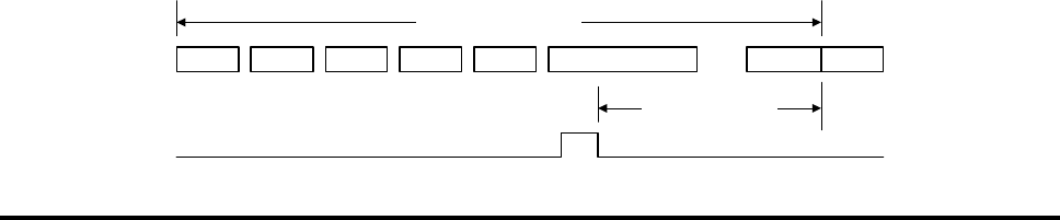
3.3.6 Setting SYNC Mode
The PF300RA SYNC mode can be set to None, Master or Slave, by click the corresponding radio
button. The default SYNC pulse timing values are set according to field tests.
If required, the SYNC pulse timing can be adjusted as explained below.
• SYNC Slave Mode: in this mode, you can adjust the delay between the falling edge
of the SYNC pulse and the start of a new frame, designated SYNC to FCM, can be
adjusted in the range of 800 ±15 µsec.
FCM SDM1 SDM2 SDM3 SDM14 Activation FCMEH
9676 -0+580
µ
sec
SYNC to FCM

FP300RA User Manual
2140-72018-00-0A REV: A Page 23 Of 38
• SYNC Master Mode: in this mode, the SYNC pulse duration and timing can be
adjusted.
FCM SDM1 SDM2 SDM3 SDM14 Activation FCMEH
SYNC on time
SYNC off time
9800
µ
sec
If the Master reader is in burst mode then it will send the SYNC pulse while it in OFF state
and block the SYNC pulse while in ON state.
3.3.7 Setting Multilane Mode
The FP-300RA can support up to 4 lanes. The default setting is single lane using the MAIN
antenna connector for Tx and Rx. The multilane setting enables:
• Set multilane mode using the MAIN antenna for Tx and MULTILANE antennas for
Rx
• Set multilane mode using MULTILANE antennas for Tx and Rx.
The multilane parameters are:
• Lane: Number of active lanes (1 to 4).
• Lane Switch: Number of frames the FP-300RA will use an antenna before
switching to the next antenna.
3.3.8 Setting Lane Discrimination
The lane discrimination function enables to determine the lane in which the transponder has
been detected. The lane discrimination can be made in two ways:
• Try to determine the lane when the transponder enters the communication zone
• Try to determine the lane when the transponder leaves the communication zone.
• Try to determine the lane as soon as possible or when the transponder leaves the
communication zone.
The lane discrimination parameters are:
• Window: the number of frames, counted from the first detection of a transponder,
in which the FP-300RA tries to determine the lane. This parameter is ignored if
lane discrimination is made when the transponder leaves the communication zone.
• Min. Act. Msg: minimum number of activation message, required for reliable lane
determination.
• Min. Delta: minimum difference in the number of activation messages received
from each lane that is required for reliable lane determination.

FP300RA User Manual
2140-72018-00-0A REV: A Page 24 Of 38
3.3.9 Setting Digital I/O
The digital I/O setting enables:
• Set the digital output setting when the FP-300RA is powered up
• Set the input sense function by:
• Selecting the required input, Sense mask.
• Set the polarity for each selected input, Sense polarity.
3.3.10 Save Current Settings
After completing the FP-300RA configuration, click the Save current setting button. The FP-
300RA will save the settings and reboot.
3.4 Hot List Configuration
The hot list function enables the FP-300RA to activate a predefined transponder access
function when a transponder enters the FP-300RA communication zone. To configure the hot
list, click the Setting – Hot Lists button of the main window of the maintenance utility to
display the Hot List Control window.
3.4.1 Get Hot List Status
• Click the Get Hot Lists to get the list of currently-defined hot lists
• Select the desired hot list in the HL ID – AF ID window to view the hot list
members and the predefined auto-function.
3.4.2 Remove Hot List
• Select the desired hot list in the HL ID – AF ID window, or type the hot list ID in
the Selected HL field.
• Click the Clear hot list(s) button. If the selected hot list is 255, default hot list,
then all the hot lists will be removed, and the auto-function of the hot list 255
(default hot list), will be set to No Auto Function.
3.4.3 Add New Hot List
A new hot list is added by setting its auto function, or by adding a transponder.

FP300RA User Manual
2140-72018-00-0A REV: A Page 25 Of 38
3.4.4 Set Hot List Auto Function
• Select the desired hot list in the HL ID – AF ID window, or type the hot list ID in
the Selected HL field.
• Select the auto-function type and its parameters in the Auto Function area.
• Select the digital output setting in the Auto Function area.
• Click the Set Auto Function button.
• If the hot list is already defined, then its auto-function is replaced.
• If not, then a new hot list is defined.
3.4.5 Add Transponder to Hot List
• Select the desired hot list in the HL ID – AF ID window, or type the hot list ID in
the Selected HL field.
• Enter the transponder ID in the Selected Tag ID.
• Click Add TAG button:
• If the transponder is already a member of the specified hot list, the FP-
300RA will reject the command (reject code 07)
• If the transponder is already a member of the another hot list, the FP-
300RA will change the transponder hot list
• If the hot list is not defined, then a new hot list is defined.
3.4.6 Remove Transponder from Hot List
• Select the transponder in the Members window or enter the transponder ID in the
Selected Tag ID.
• Click the Rem TAG button. If the transponder is not in the specified hot list, the
FP-300RA will reject the command (reject code 0A).
3.4.7 Saving the Hot List
Click the Set Hot list button to make the current hot lists setting the FP-300RA default hot list.

FP300RA User Manual
2140-72018-00-0A REV: A Page 26 Of 38
Appendix A: Connection Data
A-1 Antenna Connectors
The FP-300RA has five SMA female antenna connectors, one designated MAIN and four
additional connectors designated MULTILANE 1, 2, 3 and 4.
The antenna functions depend on the selected operation mode (single lane, multiple lanes with
single transmit zone or multiple lanes with separate lane zones).
A-2 Power Input Connector
The FP-300RA has one 4-pin connector, designated DC IN, used to connect the DC input
voltage, and to enable external resetting by dry-contact closure to ground. Table A-1 lists the
pin functions.
Table A-1: DC IN Connector, Pin Functions
Pin Function
1 Input voltage
2 Ground
3 External reset (active low, with internal pull-up)
4 Ground
A-3 Digital Interface Connector
The digital interface connector is a 25-pin D-type female connector, designated I/O. The
connector is used to connect to the FP-300RA digital interface, which includes 8 inputs and 7
outputs, all referenced to ground. Table A-2 lists the connector pin functions.
Table A-2: I/O Connector, Pin Functions
Pin Designation Pin Designation Pin Designation
1 IN1 15 IN4 21 OUT4
2 IN3 16 IN6 22 OUT5
3 IN5 17 IN8 23 OUT6
4 IN7 18 OUT1 24 OUT7
5 to 13 GND 19 OUT2 25 GND
14 IN2 20 OUT3

FP300RA User Manual
2140-72018-00-0A REV: A Page 27 Of 38
A-4 Host Interface Connector
The host interface connector is 9-pin D-type female connector designated HOST. Its
communication parameters are configured by means of the MAINTENANCE interface.
The connector includes a serial asynchronous DTE interface used for connection to the host
computer. Two interfaces can be selected:
• RS-232 interface: Table A-3 lists the connector pin functions for this mode.
• RS-422 interface: Table A-4 lists the connector pin functions for this mode.
Table A-3: HOST Connector, Pin Functions for RS-232 Interface
Pin Designation Function
1 N.C. Not connected
2 TxD Transmit data output
3 RxD Receive data input
4 N.C. Not connected
5 GND Signal ground
6 N.C. Not connected
7 CTS Clear to send input
8 RTS Request to send output
9 N.C. Not connected
Table A-4: HOST Connector, Pin Functions for RS-422 Interface
Pin Designation Function
1 RxD- Receive data input (-)
2 TxD+ Transmit data output (+)
3 RxD+ Receive data input (+)
4 TxD- Transmit data output (-)
5 GND Signal ground
6 RTS- Request to send output (-)
7 CTS+ Clear to send input (+)
8 RTS+ Request to send output (+)
9 CTS- Clear to send input (-)

FP300RA User Manual
2140-72018-00-0A REV: A Page 28 Of 38
A-5 Maintenance Interface Connector
The maintenance interface connector is 9-pin D-type female connector designated
MAINTENANCE. The connector includes the serial asynchronous RS-232 DTE interface used
for connection to a PC running the maintenance utility. Its communication parameters are 9600
bps, 1 start bit, 8 data bits, no parity, one stop bit. Table A-5 lists the connector pin functions.
Table A-5: MAINTENANCE Connector, Pin Functions
Pin Designation Function
1 N.C. Not connected
2 TxD Transmit data output
3 RxD Receive data input
4 N.C. Not connected
5 GND Signal ground
6 N.C. Not connected
7 RTS Request to send output
8 CTS Clear to send input
9 N.C. Not connected
A-6 Auxiliary Interface Connector
The auxiliary interface connector is 9-pin D-type female connector designated AUX. The
connector includes a serial asynchronous RS-232 DTE interface used for connection to
auxiliary devices, or for synchronization pulses. Its communication parameters are configured
by means of the MAINTENANCE interface.
• RS-232 interface: A-6 lists the connector pin functions for this mode.
• RS-422 interface: A-4 lists the connector pin functions for this mode.
Table A-6: AUX Connector, Pin Functions for RS-232 Interface
Pin Designation Function
1 N.C. Not connected
2 TxD Transmit data output or SYNC pulse output
3 RxD Receive data input or SYNC pulse input
4 N.C. Not connected
5 GND Signal ground
6 N.C. Not connected
7 CTS Request to send output
8 RTS Clear to send input
9 N.C. Not connected

FP300RA User Manual
2140-72018-00-0A REV: A Page 29 Of 38
Table A-7: AUX Connector, Pin Functions for RS-422 Interface
Pin Designation Function
1 RxD- Receive data input (-)
2 TxD+ Transmit data output (+)
3 RxD+ Receive data input (+)
4 TxD- Transmit data output (-)
5 GND Signal ground
6 RTS- Request to send output (-)
7 CTS+ Clear to send input (+)
8 RTS+ Request to send output (+)
9 CTS- Clear to send input (-)
FP300RA User Manual
2140-72018-00-0A REV: A Page 30 Of 38
Appendix B: Maintenance Utility
B-1. Scope
This Appendix provides installation and general operating instructions for the FP-300RA
maintenance utility, version 1.0.
The FP-300RA maintenance utility runs under Microsoft Windows 2000, and uses the
standard Windows user interface. The utility is provided on a standard CD.
The information presented in this Appendix assumes that the user is familiar with the use of
Windows applications. If additional information is necessary, refer to the Windows 2000
User’s Reference Manual, available from Microsoft Corp.
B-2. Installation
B-2.1 Hardware and Software Requirements
The PC used to run the maintenance utility must have Windows 2000 already installed and
running before starting the installation of the utility.
Make sure the PC has a free serial communication (COM) port for communication with the
FP-300RA.
B-2.2 Installation Procedure
• Copy the files provided on the CD to the desired folder.
• Prepare a shortcut to the utility .EXE file on the desktop.
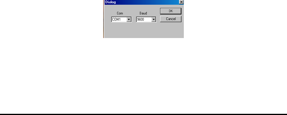
B-2.3 Preliminary Configuration
• Start the utility, e.g., by clicking the desktop shortcut.
• You will see a dialog box that prompts you to select the serial communication
(COM) port that will be used for communication with the FP-300RA.
• Select the desired port, e.g., COM1, on the Com option menu, and then click
the OK button to confirm and close the dialog box.
Figure B-1. COM Port Selection Box
You will see the main window.
FP300RA User Manual
2140-72018-00-0A REV: A Page 31 Of 38
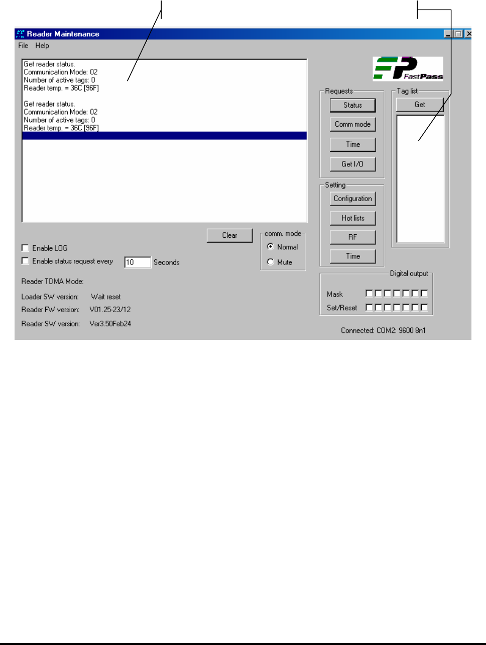
B-3. Main Window
Figure B-2 shows a typical main window, as seen after the PC is connected to an operational
FP-300RA. The window has a menu bar with two items: File and Help. The following sections
explain the various areas of the window.
Figure B-2 Typical Main Window
B-3.1 Monitor Area
The monitor area displays the request/command messages sent to the FP-300RA and its
response.
B-3.2 Active List Area
The active list area displays the transponders that are currently in the FP-300RA
communication zone. The active list is stored in the FP-300RA and can be read by clicking the
Get button in the Tag List area.
Monitor area
Active list area

FP300RA User Manual
2140-72018-00-0A REV: A Page 32 Of 38
B-3.3 Log File
The information displayed in the monitor area can be recorded in a log file by checking the
Enable Log box.
The log file is saved in the current directory. The file name is FP-300RA, followed by file
opening date and time. The current log file will be closed and a new one will be opened
according to the parameters defined by means of the Log Control window.
B-3.4 Sending Periodic Status Request
The maintenance utility can be configured to automatically send status requests by checking
the Enable Status Request Every box, and then entering the desired interval, in seconds, in
the adjacent field.
B-3.5 Setting the Communication Mode
The radio buttons in the Comm Mode are used to select the FP-300RA communication mode:
• Normal – normal operation.
• Mute – transmission disabled. For your safety, before replacing an antenna, the
FP-300RA must be turned off or set to Mute.
B-3.6 Setting/Resetting the Digital Output Port
The maintenance utility can set or reset any one of the seven FP-300RA digital outputs by
setting the required bit mask in the Digital Output are:
• To set a bit (“1”), check the bit box.
• To reset a bit (“0”), uncheck the bit box.
B-3.7 Information Fields
The main window contains the following information fields:
• Connected: displays the configured COM port, its data rate and the word format
(data bits – parity – stop bits).
• Reader TDMA mode
• FP-300RA loader software version (updated after cold reset)
• FP-300RA firmware version (updated by self-test result)
• FP-300RA application software version (updated by self-test result).

FP300RA User Manual
2140-72018-00-0A REV: A Page 33 Of 38
B-3.8 Requests Area
The user can click buttons in the Requests area to cause the maintenance utility to send the
following request for information to the FP-300RA:
• Status
• Current FP-300RA communication mode
• FP-300RA current time
• Digital I/O settings.
The FP-300RA response is displayed in the monitor window and, if applicable, updates the
main window information field.
B-3.9 Setting Area
The buttons in the Setting area are used to configure the following FP-300RA parameters:
• Configuration (system parameters)
• Hot list parameters
• RF parameters
• Set FP-300RA time.
Each button, except Time, opens a control window. The Time setting uses the PC time.

FP300RA User Manual
2140-72018-00-0A REV: A Page 34 Of 38
B-4. File Menu
Figure B-3 shows the File menu of the maintenance utility.
Figure B-3: File Menu Structure
The functions of the items included on the File menu are as follows:
Config COM Configure the PC COM port to be connected to the FP-300RA.
Reset Reader Send a reset command to the FP-300RA.
Self Test Send a self-test command to the FP-300RA.
Upgrade Start FP-300RA software/firmware upgrade process.
Msg monitor Display the command/response messages details.
Log control Enable selecting the maximum number of lines in the log file, or the
maximum time the log file remains open, even when the specified number
of lines has not yet been reached. In either case, the current log file is
closed and anew one is opened.
Exit End the FP-300RA maintenance utility.
FP300RA User Manual
2140-72018-00-0A REV: A Page 35 Of 38
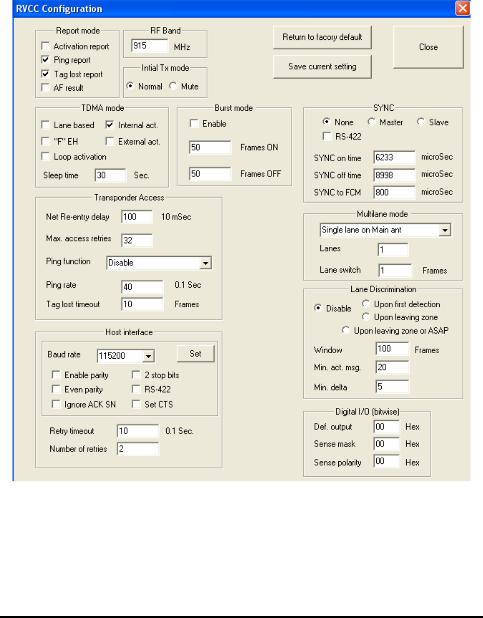
B-5. FP-300RA Configuration Window
The FP-300RA Configuration window, shown in Figure B-4, is used to select the system
configuration parameters. In most cases, the configuration change is made when the focus is moved
from the changed parameter’s field.
For a description of the system parameters and their range of values, refer to the FP-300RA
Configuration Table section in Appendix C.
Figure B-4: Typical FP-300RA Configuration Window
FP300RA User Manual
2140-72018-00-0A REV: A Page 36 Of 38
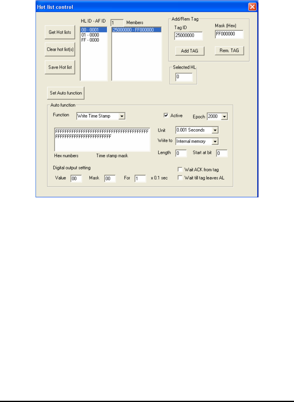
B-6. Hot List
The hot list functionality is described in Chapter 3. A typical Hot List Control window is shown in
Figure B-5
Figure B-5: Typical Hot List Control Window
The window includes the following buttons:
Get Hot Lists Get currently set hot lists.
Clear hot list(s) Clear the selected hot list. Select 0 to clear all the hot lists.
Save HL Save the current hot list setting as default setting.
Load HL from file Load the hot list settings from a script file.
Add TAG Add a selected transponder with Mask to a selected hot list.
Rem. TAG Remove a transponder with Mask from a hot list.
Set Auto function Set the auto-function for the selected hot list.
B-6.1 Auto-Function
The auto-function is selected from the Function list. When a function is selected, the relevant data
field will be opened.
The Digital output setting is not applicable and the mask field should be 0.
FP300RA User Manual
2140-72018-00-0A REV: A Page 37 Of 38
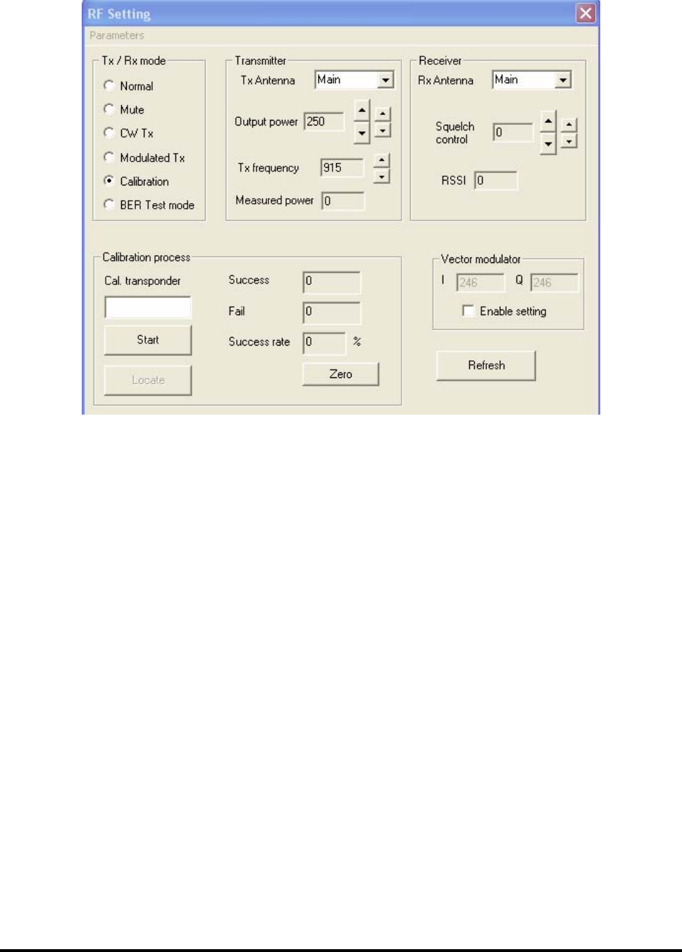
B-7. RF Setting Window
Figure B-6 shows a typical RF Setting window.
Figure B-6: Typical RF Setting Window
B-7.1 Get Button
Its function it to get the current RF parameters. When using the CW or modulated mode, the
actual transmit output power is measured and reported.
B-7.2 Set Default Button
Its function is to set the current RF parameters as the FP-300RA default RF parameters.
B-7.3 Tx Mode
Selects the transmitter operating mode:
Normal The TDMA air interface is active according to the current configuration.
Mute The TDMA air interface is inactive (no transmission, no reception).
CW The FP-300RA continuously transmits a CW signal.
Modulated Tx The FP-300RA continuously transmits a modulated signal.
Calibration The TDMA air interface is active; the transmission is made via the antenna
selected with Tx Antenna and the reception is made via the antenna selected
with Rx Antenna.
BER Test
mode
Used for FP-300RA receiver testing

FP300RA User Manual
2140-72018-00-0A REV: A Page 38 Of 38
B-7.4 Transmitter
Enables selecting the Tx antenna and the transmitter output power:
• In the normal mode, the selected setting will take effect when the FP-300RA will
switch to this antenna.
• In the calibration mode, the FP-300RA will switch to the selected antenna and the
selected output power will be adjusted to the new value on next frame.
B-7.5 Receiver
Enables selecting the Rx antenna and the receiver digital squelch:
• In the normal mode, the selected setting will take effect when the FP-300RA will
switch to this antenna.
• In the calibration mode, the FP-300RA will switch to the selected antenna and the
selected digital squelch will be adjusted to the new value on next frame.
B-7.6 Vector Modulator
The vector modulator is configured by the manufacturer and must not be changed unless
explicitly instructed to do so by an authorized Telematics Wireless representative.
B-7.7 Calibration Process
The calibration process section of the RF setting window is open when calibration Tx mode is
selected. The calibration procedure is explained in Appendix E