Telemotive Controls E10647 Remote Control Transmitter User Manual telePilotTR12B
Telemotive Industrial Controls Remote Control Transmitter telePilotTR12B
Exhibit D Users Manual per 2 1033 b3

TR12 AND TX12 10/19/2001
I
IN
NS
ST
TA
AL
LL
LA
AT
TI
IO
ON
N
A
AN
ND
D
U
US
SE
ER
RS
S
M
MA
AN
NU
UA
AL
L
TELEMOTIVE
telePilotTM SERIES
TR12 AND TX12
R
RA
AD
DI
IO
O
C
CO
ON
NT
TR
RO
OL
L
S
SY
YS
ST
TE
EM
M
telemotive®
Industrial Controls
175 Wall Street
Glendale Heights, IL 60139-1985
Phone: 630-582-1111, Toll Free: 888-687-4400
Website: www.telemotive.com
This page intentionally left blank.

Table of Contents
1
1- Service Information...........................................................................................................................2
2- Radio Controlled Safety ....................................................................................................................3
3- General System Information .............................................................................................................9
4- Installation Procedure......................................................................................................................11
5- Operation .................................................................................................................. 14
6- Wiring Diagram...............................................................................................................................18
7- Programming...................................................................................................................................21
8- Servicing .........................................................................................................................................21
9- Spare Parts.......................................................................................................................................29

Section 1 – Service Information
2
1-1. Service Information.
For questions regarding service or technical
information or ordering replacement parts, ask for
Telemotive Customer Care. Telemotive’s normal
business hours are Monday through Friday 8:00 AM
to 5:00 PM Central Standard Time. After hours
emergency technical service is available.
For new product orders or quotations, ask for
Telemotive Sales.
Telemotive Industrial Controls
175 Wall Street
Glendale Heights, IL 60139-1985
USA
Telephone: (630) 582-1111
In the USA toll free: (888) 687-4400
Website: http://www.telemotive.com/
Manuals for downloading are available for many
products at the Telemotive website.
E-mail info@telemotive.com
Telemotive Fax Numbers:
Main: (630) 582-1195
Sales: (630) 582-1204
Customer Care: (630) 582-1205
Section 2 – Radio Controlled Safety
3
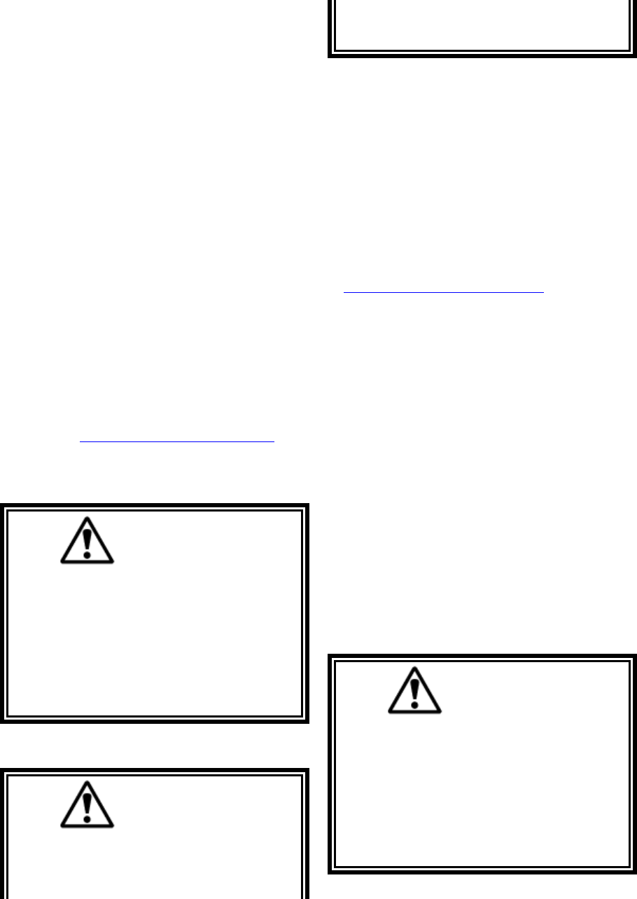
2-1. Warnings, Cautions and Notes.
Through out this document WARNING, CAUTION
and NOTE statements have been deliberately placed
to highlight items critical to the protection of
personnel and equipment.
WARNING – A warning highlights a essential
operating or maintenance procedure, practice, etc.
which if not strictly observed, could result in injury
or death of personnel, or long term physical hazards.
Warnings are highlighted as shown below:
WARNING
CAUTION – A caution highlights an essential
operating or maintenance procedure, practice, etc.
which if not strictly observed, could result in damage
to, or destruction of equipment, or loss of functional
effectiveness. Cautions are highlighted as shown
below:
CAUTION
NOTE – A note highlights an essential operating or
maintenance procedure, condition or statement. Notes
are shown as below:
NOTE
WARNINGS, CAUTIONS AND NOTES SHOULD
NEVER BE DISREGARDED.
The safety rules in this section are not intended to
replace any rules or regulations of any applicable
local, state, or federal governing organizations. The
following information is intended to be used in
conjunction with other rules or regulations already in
existence. It is important to read all of the safety
information contained in this section before installing
or operating the Radio Control System.
2-2. Critical Installation Considerations.
WARNING
ALL EQUIPMENT MUST HAVE A MAINLINE
CONTACTOR INSTALLED AND ALL TRACKED
CRANES AND SIMILAR EQUIPMENT MUST
HAVE A BRAKE INSTALLED. FAILURE TO
FOLLOW THIS WARNING COULD RESULT IN
SERIOUS INJURY OR DEATH AND DAMAGE
TO EQUIPMENT.
WARNING
ON ALL REMOTE CONTROLLED CRANES AN
AUDIBLE AND/OR VISUAL WARNING MEANS
MUST BE PROVIDED. THESE AUDIBLE
AND/OR VISUAL WARNING DEVICES MUST
MEET ALL GOVERNMENTAL REQUIRE-
MENTS. FAILURE TO FOLLOW THIS WARN-
ING COULD RESULT IN SERIOUS INJURY OR
DEATH AND DAMAGE TO EQUIPMENT.
WARNING
REMOVE ALL ELECTRICAL POWER FROM
THE CRANE OR MACHINERY BEFORE AT-
TEMPTING ANY INSTALLATION PROCE-
DURES. DE-ENERGIZE AND TAG OUT ALL
SOURCES OF ELECTRICAL POWER BEFORE
TOUCH TESTING ANY EQUIPMENT. FAILURE
TO FOLLOW THIS WARNING COULD RESULT
IN SERIOUS INJURY OR DEATH AND DAM-
AGE TO EQUIPMENT.

Section 2 – Radio Controlled Safety (Continued)
4
WARNING
THE DIRECT OUTPUTS OF THIS PRODUCT
ARE NOT DESIGNED TO INTERFACE DI-
RECTLY TO TWO STATE SAFETY CRITICAL
MAINTAINED FUNCTIONS, I.E., MAGNETS,
VACUUM LIFTS, PUMPS, EMERGENCY
EQUIPMENT, ETC. A MECHANICALLY LOCK-
ING INTERMEDIATE RELAY SYSTEM WITH
SEPARATE POWER CONSIDERATIONS MUST
BE PROVIDED. FAILURE TO FOLLOW THIS
WARNING COULD RESULT IN SERIOUS IN-
JURY OR DEATH AND DAMAGE TO EQUIP-
MENT.
2-3. General.
Radio controlled overhead cranes and other material
handling equipment operate in several directions.
They are large, bulky pieces of equipment that handle
heavy loads efficiently at high speeds. Quite
frequently, the equipment is operated in areas where
people are working on the floor below. The crane
operator must exercise extreme caution at all times.
Workers must constantly be alert to avoid accidents.
The following rules have been included to indicate
how your careful and thoughtful actions may prevent
injuries, damage to equipment, or even save a life. If
radio controlled material-handling equipment is
operated from the cab, special care must be taken to
secure the transmitter. Refer to section titled Section
2-10. Boarding The Crane for specific safety rules.
2-4. Persons Authorized To Operate Radio
Controlled Cranes.
Only properly trained persons designated by
management should be permitted to operate radio-
controlled cranes.
Radio controlled cranes should not be operated by
any person who cannot read or understand signs,
notices and operating instructions that pertain to the
crane.
Radio controlled cranes should not be operated by
any person with insufficient eyesight or hearing or by
any person who may be suffering from a disorder or
illness or is taking any medication that may cause
loss of crane control.
2-5. Training Checklist For Crane Operators.
Anyone being trained to operate a radio-controlled
crane should possess as a minimum the following
knowledge and skills before operating the crane:
The operator should have knowledge of hazards
peculiar to crane operation.
The operator should have knowledge of the safety
rules for radio-controlled cranes.
The operator should have the ability to judge distance
or moving objects.
The operator should have knowledge of the radio
transmitter.
The operator should know the limit switch test
procedure.
The operator should know, where authorized,
instructions for plugging motions.
The operator should have knowledge of the use of
crane warning lights and alarms.
The operator should have knowledge of observing
crane signal lights.
The operator should be trained to avoid striking any
obstructions.
The operator should have knowledge of the proper
clearance of lifts or hooks before moving bridge or
trolley.
The operator should have knowledge of the proper
storage space for radio control box when not in use.
The operator should be trained in transferring radio
control box to another person.
The operator should be trained how and when to
report unsafe or unusual operating conditions.
The operator should be trained how to exhibit caution
in approaching bridge or trolley bumpers.
The operator should know equipment capacity.
The operator should be trained in making lifts below
floor level.
The operator should be trained in making side pulls.
The operator should know how to keep himself and
other people clear of lifts and to avoid "pinch" points.
Section 2 – Radio Controlled Safety (Continued)
5
The operator should know cable and hook inspection
procedures.
The operator should know procedures for testing
hoist, trolley, and bridge brakes.
2-6. Operating Area.
Aisles between equipment, stock, etc., should be free
of obstructions so the crane operator can move freely.
These aisles should be a minimum of meter wide, or
meet local regulations.
Crane operators should always position themselves
for the best view of the crane they are controlling.
The crane should never be operated blindly. The
operator should stay as close to the crane load as
possible. Operators should never position themselves
in a "pinch" point.
2-7. Transmitter Unit.
Transmitter switches should never be mechanically
blocked ON or OFF for any crane motion. When not
in use turn the transmitter OFF. A secure storage
space should be provided for the transmitter unit and
the transmitter unit should always be placed there
when not in use. This precaution will prevent
unauthorized people from operating the crane.
Spare transmitters should be stored in a secure
storage space and only removed from the storage
space after the current transmitter in use has been
turned OFF, taken out of the service area and
secured.
2-8. Operating The Crane.
2-8.1. Pre-operation Test.
At the start of each work shift, or when a new op-
erator takes control of the crane, operators shall do as
a minimum the following steps before making lifts
with any crane or hoist:
Test the upper-limit switch. Slowly raise the
unloaded hook block until the limit switch trips.
When checking limit switches the hoist should be
centered over an area free of personnel and
equipment.
Visually inspect the hook, load lines, trolley, and
bridge as much as possible from the operator's
station; in most instances, this will be the floor of the
building.
The bridge and trolley brakes should be tested. On
transmitter units equipped with two or more speeds,
use the "lowest" speed when testing braking devices.
When lifting maximum loads, the crane operator
should test the hoist brakes by raising the load a few
inches from the floor. If the brakes do not hold, the
load should immediately be lowered to the floor.
If provided, test the lower-limit switch.
Test all warning devices.
Test all direction and speed controls for both bridge
and trolley travel.
Test all bridge and trolley limit switches, where
provided, if operation will bring the equipment in
close proximity to the limit switches.
Test the transmitter emergency stop.
Test the hoist brake to verify there is no drift without
a load.
If any crane or hoist that fails any of the above tests
notify the supervisor and lock out and tag for repair.
2-8.2. General rules for operation.
Consult the crane manufacturer, local and
governmental regulations for complete rules of
operation. In general the following rules apply to
remotely controlled cranes:
The limit switches should never be used as a regular
stopping device. They are intended to be protective
devices.
Do not make lifts in excess of the equipment rated
capacity.
The bridge and trolley should be centered directly
over the load when the load is raised to prevent
swinging when making lifts.
A crane designed for this purpose and only with
supervisor permission should make side pulls. When
a lift is being made, the crane operator should not be
positioned in the line of travel. The crane or hoist
should be operated from a position either to the side
or opposite from the direction of travel.
When raising or lowering a load, proceed slowly and
make certain the load is under control. Tag lines
should be used for handling unusual lengths or bulky
loads. Remove slack from chains or slings gradually.
Section 2 – Radio Controlled Safety (Continued)
6
Make certain all personnel are clear before making a
lift.
The crane operator should keep all body parts away
from the lift and should never be positioned under the
lift.
Do not make a lift or move a load if anyone is in a
location where they could be struck by the crane or
the load.
If the crane operator is being helped, the crane should
not be moved until the helper signals they are clear of
the crane and its load.
When a load is hanging from the crane hook and the
crane is being moved, the crane operator should
sound all warning devices frequently.
Loads should not be carried over workers heads. If a
worker is in the path of crane travel, the crane
operator should stop the crane and clear the area
before proceeding.
Runway stops or other cranes should never be
bumped into.
When moving the crane, the crane operator should be
sure that the hook block and attachments or cables
would not catch on nearby equipment. Slings, chains,
or cables should never be dragged along the floor.
Unless required for operator safety, gloves should not
be worn when operating the transmitter unit.
All loose materials or parts should be removed from
the load before starting the lift.
The crane operator should always hoist lifts high
enough to clear all equipment and workers.
The crane operator should never permit anyone to
ride on the load or hook except when authorized by
the supervisor.
When another crane on the same runway is stationary
with a load hanging, the crane operator should
maintain a safe distance between the stationary crane
and the one under their control.
Never leave suspended loads unattended. In an
emergency, if the crane is inoperative and a load
suspended, notify the supervisor immediately,
barricade and post signs on the floor beneath crane
and load.
If power to the crane is removed, the crane operator
should turn the transmitter unit OFF and keep it OFF
until power is restored.
If the crane fails to respond properly, the crane
operator should stop operation, turn the transmitter
unit OFF and immediately report the condition to
their supervisor.
Outdoor cranes, which are subject to movement by
wind, should be securely anchored when left
unattended. If the crane is equipped with bridge
brakes, the parking brake should be set immediately.
2-9. Boarding The Crane.
The crane should not be boarded without permission
of the supervisor.
The crane operator should turn off the transmitter and
take it with them when boarding the crane.
If more than one person is boarding the crane, one
person should be made responsible for ensuring all
personnel are off the crane before the system is
returned to operation.
2-10. Crane Maintenance and Repair.
Qualified personnel must maintain a regularly, i.e.,
such as monthly, scheduled crane inspection. During
this crane inspection the functionally and safety of
the crane remote control must also be tested. The
inspection shall include, but be not limited to items
listed in Section 2-13. Condition Of The Radio
Controlled Crane. Consult crane manufacturer, local
and governmental regulations for recommended
inspection intervals and proper inspection
procedures. Problems noted during this inspection
must be repaired before using the crane or the remote
control.
Minor repairs include routine maintenance and
repairs such as greasing, cleaning and control
troubleshooting. All other repairs should be con-
sidered major. If the repair crew consists of more
than one person, one person should be designated as
the repair crew leader with the following
responsibilities. If the repair crew consists of only
one person, that person has the following
responsibilities:
For minor repairs warning signs should be placed on
the floor beneath the crane or suspended from the
crane. For major repairs, the floor area below the
crane should be roped off.

Section 2 – Radio Controlled Safety (Continued)
7
When major repairs are to take place, all persons
operating other cranes on the same or adjacent
runways, if any, must be notified prior to starting
repairs. Notification should include the nature of the
repair, safeguards provided, and movement
limitations while repairs are in progress.
When practical, radio controlled cranes which cannot
be moved during repairs must be protected against
being bumped by other cranes on the runway.
Bumpers should be installed on the exposed side or
sides of the crane under repair. They should be
placed as far away as possible. The location of these
bumpers should be indicated by red lights placed so
that they are clearly visible to other crane operators
traveling on the same runway. When it is not possible
to use bumpers, red lights must be placed so they are
clearly visible to other crane operators traveling on
the same runway to indicate the restricted travel zone.
All crane operators on the same runway must be
informed of the repair effort and thoroughly
instructed to what their operations are limited to and
informed they will be notified when repairs are
completed.
If any hazard involving the repairmen exists when
there is a runway adjacent to the crane under repair,
the adjacent runway should be blocked off as
described above. When it is necessary to continue
crane operation on the adjacent runways warning
lights must be installed and be visible to operators of
cranes on those runways. All cranes should come to a
complete stop prior to entering the restricted area and
should proceed through this area only after receiving
permission from a signal person designated for this
purpose. Access of persons to and from the crane
being repaired should be under control of the repair
crew leader.
When boarding the crane, the transmitter should be
turned OFF and the transmitter should remain with
the repair crew leader. The leader should board the
crane first, open and lock out the main switch, and
then signal the other members of the crew it is safe to
board the crane.
If work on the crane is to be done in areas not
protected by standard handrails, the repair crew
should wear approved safety belts.
All tools and equipment should be moved onto the
crane by the use of hand lines. The tools and
equipment should be adequately secured to the hand
lines.
If it is necessary to have the crane control circuits
energized, all power circuits for crane movement
must be opened prior to energizing the control
circuits.
All personnel and tools should be moved to a safe
spot before moving the crane during repairs.
Headroom is at a minimum in some crane cabs and
on some crane walkways. Caution should be
exercised when boarding or working on cranes. Hard
hats should be worn whenever possible.
When repairs are finished, all personnel, tools and
repair equipment should be removed before
energizing the crane circuits.
2-11. Using The Crane As A Work Platform.
When the crane is to be used as a stationary work
platform, follow all rules provided in Section 2-11.
Crane Maintenance and Repair. When it is necessary
for the crane to be moved from time to time, the
crane operator should board the crane with the
transmitter unit. The crane operator should ensure all
personnel working on the crane are in a secure
position before moving the crane to the next
workstation. It should also be the crane operators
responsibility to ensure the main switch is open and
locked down before work is resumed.
WARNING
THE CRANE OPERATOR SHOULD NOT AT-
TEMPT TO REPAIR ANY OF THE ITEMS
STATED BELOW. THE CRANE CONDITION
SHOULD BE REPORTED TO THE SUPERVISOR.
FAILURE TO FOLLOW THIS WARNING COULD
RESULT IN SERIOUS INJURY OR DEATH AND
DAMAGE TO EQUIPMENT.
2-12. Condition Of The Radio Controlled Crane.
If the crane fails to respond properly, the crane
operator(s) should notify their supervisor. When
serious conditions are noticed (conditions that make
the crane unsafe to operate), the crane should be shut
down immediately and the supervisor notified. The
following is a list of some of the items that should be
included in the report. (See the crane manufacturer
for specifics and possible additional items):

Section 2 – Radio Controlled Safety (Continued)
8
Condition of hoisting cable and hook block (broken
strands, clipped sheave wheels, etc.).
Condition of brakes (hoist, trolley, and bridge). (no
bluing, rivets on shoes showing, glazing, etc.).
Condition of trolley and rail stops.
Condition of bridge structure.
Condition of festoon system.
Broken welds in any part of the crane structure.
Proper fluid levels and lubrication.
Condition of bridge and trolley stops.
Carbon dust or signs burning on the covers of motors.
Indication of fluid, oil or grease leaks.
Condition of rail sweeps.
Walkways required handrails and ladders are in
place, sturdy and not loose.
Protective guards are in place for all moving parts.
Alignment of bridge (screeching or squealing wheels
indicate bridge is out of line).
Broken, cracked, or chipped rails on trolley or
runway.
Condition of limit switches.
Condition of electrical and mechanical control
(electrical or mechanical defects which cause faulty
operation such as un-commanded stopping or starting
of any crane motions, warning devices, lights, or
auxiliary functions).
Condition of gears (grinding or squealing may
indicate foreign materials in gear teeth or a lack of
lubrication.
All controls especially E-STOPS are in place and in
working order.
Frequent relay tripping of power circuits.
Mechanical parts loosened by vibration (loose rivets,
covers, bolts, etc.).
Uneven riding (worn or damaged wheels).
Condition of collector shoes or bars.
Condition of warning or signal lights and horns.
(burned out or broken).
2-13. Batteries
WARNING
KNOW AND FOLLOW PROPER BATTERY
HANDLING, CHARGING AND DISPOSAL PRO-
CEDURES. IMPROPER BATTERY PROCE-
DURES CAN CAUSE BATTERIES TO EXPLODE
OR DO OTHER SERIOUS DAMAGE. FAILURE
TO FOLLOW THIS WARNING COULD RESULT
IN SERIOUS INJURY OR DEATH AND DAM-
AGE TO EQUIPMENT.
2-13.1. Battery Handling.
Use only batteries approved by Telemotive for the
specific product.
Do not dispose of a battery pack in fire; it may
explode.
Do not attempt to open the battery pack.
Do not short circuit battery.
For intrinsically safe environments only used
specified Telemotive intrinsically safe batteries.
Keep the battery pack environment cool during
charging operation and storage, (i.e., not in direct
sunlight or close to a heating source).
2-13.2. Battery Charging.
Please familiarize all users with the instructions of
the charger before attempting to use.
Use only Telemotive approved chargers for the
appropriate battery pack.
Do not attempt to charge non-rechargeable battery
packs.
Avoid charging the battery pack for more than 24
hours.
Do not charge batteries in a hazardous environment.
Do not short charger.
Section 2 – Radio Controlled Safety (Continued)
9
Do not attempt to charge a damaged battery.
Do not attempt to use a battery that is leaking,
swollen or corroded.
Charger units are not intended for outdoor use. Use
only indoors.
2-13.3. Battery Disposal.
Before disposing of batteries consult local and
governmental regulatory requirements for proper
disposal procedures.

Section 3 – General System Information
10
3-1. General System Information.
The Telemotive Radio Control System (system)
provides remote control of overhead cranes using
radio signals. The system consists of a hand held
portable battery operated transmitter unit and a fixed
station receiver unit.
A unique 16-bit code (Access Code) for each system
is preset in every transmitter and receiver. The
receiver considers any received signal, which does
not match the receiver access code setting, invalid.
The Access Code is made up of 16-bits (65,000
combinations) and no two similar codes are assigned
to any two Telemotive systems.
Up to four systems may be used with the same
frequency in a 600-foot area (220 meters). Each
transmitter operating on the same frequency may be
operated in close proximity, not less than six feet (1.9
meters), to each other.
3-2. TMS Low Power Signaling.
TMS (Time Multiplexed Signaling) is a Telemotive
propriety high-speed packet data system. The system
software is structured to minimize "on the air"
transmission time of any transmitter. This allows for
multiple transmitters to share a common frequency.
The TMS system is designed so that a transmitter will
send a signal for a predetermined ON time, and then
will turn OFF. The length of transmitter ON time is
referred to as data burst or packet. The packet length
is a function of the quantity of data to be sent, and the
data rate (baud). Once the packet is sent, the
transmitter will turn OFF. This allows for other
transmitters to time-share the same frequency when a
transmitter has turned OFF. The TMS system soft-
ware determines the OFF period and repetition rate of
the ON period. Since each system has its own access
code, up to 4 transmitters can share and have equal
access to the same frequency. TMS also allows for
reduced battery consumption and extended battery
life.
These systems have low power pulsed signaling,
FCC certified under Part 15 Telecommunications
Code of Regulations, no license is required. The
transmitter unit is frequency modulated, low power
and is certified under the appropriate regulations. A
license is not required for the transmitter or operator.
Modifications to the RF section of this system are not
permitted and could void FCC certification.
3-3. System Specifications.
Channel Designations:
AK01 - 439.8 MHz AK06 - 438.8 MHz
AK02 - 439.6 MHz AK07 - 438.6 MHz
AK03 - 439.4 MHz AK08 - 438.4 MHz
AK04 - 439.2 MHz AK09 - 438.2 MHz
AK05 - 439.0 MHz AK10 - 438.0 MHz
AK11 - 437.8 MHz AK16 - 436.8 MHz
AK12 - 437.6 MHz AK17 - 436.6 MHz
AK13 - 437.4 MHz AK18 - 436.4 MHz
AK14 - 437.2 MHz AK19 - 436.2 MHz
AK15 - 437.0 MHz AK20 - 436.0 MHz
For special applications only:
AKA00 433.100 MHz
Operating Temperature: –22° F to +158° F (-30º C to
+70º C) ambient.
Humidity: up to 95 % (non-condensing).
Typical Operating Range: 200 feet (70 meters).
Rating of output relays (including Master Relay): 16
Amp 277 VAC/24 VDC, 1 HP 240 VAC.
3-4. Transmitter Unit.
The transmitter is battery operated has an ON and
OFF switch, E-STOP, motor controls and auxiliary
controls used for such item warning indicators.
LED’s mounted on the front panel provide indication
of battery voltage, ON/OFF, Modes and data
transmission status.
A power down feature allows the transmitter and the
receiver unit to turn OFF if no keys are pressed for
predetermined number of minutes. The transmitter
unit must again be turned ON. The unit uses pulsed
operation for extremely long battery life. A
configuration of the system is available without
automatic timeout.
Housings are designed of high impact, chemical
resistant, materials. The antenna for the unit is
internal. A strap or belt is provided for carrying the
transmitter.
Section 3 – General System Information (Continued)
11
3-5. Receiver Unit.
The receiver unit consists of a synthesized RF
module, built in antenna, integral power supply,
microprocessor controlled output motor control and
auxiliary function relays and mainline contactor
relay. The receiver unit contains circuitry, which
matches the frequency and access code of the
transmitter.
Section 4 – Installation Procedure
12
4-1. Pre-Installation Considerations.
To ensure reliable and safe operation of the
system, the following items must be considered
before installing the receiver unit.
If the receiver is mounted outdoors or in a
corrosive environment, the receiver unit cabinet
must be housed in a protective enclosure.
The receiver unit should not be subjected to
moisture.
WARNING
THE RECEIVER UNIT OR RELAYS ARE
NOT RATED AS EXPLOSION PROOF. THE
RECEIVER UNIT MUST NOT BE IN-
STALLED IN EXPLOSIVE ENVIRONMENTS
UNLESS APPROPRIATE SECONDARY EN-
CLOSURE MEASURES ARE TAKEN. FAIL-
URE TO FOLLOW THIS WARNING COULD
RESULT IN SERIOUS INJURY OR DEATH
AND DAMAGE TO EQUIPMENT.
4-2. Receiver Unit Mounting Location
Considerations.
Ensure the mounting location is as far as possible
from exposed trolley wires and sources of
electromagnetic or radiated noise
The receiver unit requires a mounting area
approximately xxxx 8" (20 cm) wide by 11" (28
cm) high. A depth of at least 6" (15 cm) must be
provided to allow the cabinet door to open.
The mounting surface must be smooth and
continuous. Mounting the cabinet on uneven
surfaces could cause warpage or stress internal
components.
The receiver unit may be mounted in any
position. Greatest radio control range is obtained
when the receiver unit is mounted with the
antenna pointed straight up.
If possible, avoid installing receiver unit to a
surface where high vibration or shock is present.
If this cannot be avoided, use appropriate shock
mounts.
4-3. Antenna Mounting Considerations.
The antenna is internal and requires no
additional mounting. The antenna is at the top of
the receiver cabinet and should not be placed
near large metal objects that could be close to or
cover the top of the box. Allow at least six
inches above the top of the box for clearance.
4-4. Line Input Considerations.
WARNING
THE UNIT MUST BE WIRED TO THE COR-
RECT VOLTAGE, AND BE CONNECTED TO
THE CORRECT TERMINAL AS REQUIRED
BY THE ACTUAL LINE VOLTAGE, FAIL-
URE FOLLOW THIS WARNING COULD RE-
SULT IN SERIOUS INJURY OR DEATH AND
DAMAGE TO EQUIPMENT.
The receiver unit has direct connect provisions
for operation from 120 (nominal), 50-60 Hz
power.
For applications where line voltage deviation
exceeds 20% of nominal values if line voltage is
not between
95-130 VAC or 190-260 VAC or if 440 VAC
power is used, a step up or step down
transformer must be used.
NOTE
THE RECEIVER UNIT SHOULD NOT BE
CONNECTED TO LINES CONTAINING
EXCESSIVE POWER UP TRANSIENTS OR
CONTINUOUS COMMUTATOR NOISE. A
LINE CONDITIONER MAY BE NECESSARY
IN SOME INSTALLATIONS.
4-5. Wiring Considerations.
1. Read this manual before installation.
2. Please observe appropriate local and
National Electrical Codes when wiring electrical
devices.
3. Do not connect or disconnect wiring, or
perform circuit checks while the power is turned
on.
Section 4 – Installation Procedure (Continued)
13
4. The motor wiring should be in a separate
metal conduit from the power wiring, which
should also be in metal conduit.
5. Low voltage wires shall be wired with
proper low voltage class wiring procedures.
6. Control wiring as well as antenna wiring
shall be in separate conduit and shall be kept as
short as possible.
7. All terminals shall be tightened to specified
terminal torque 4.4 IN-LBS (.5 N·m). unless
otherwise specified.
8. Remove excess metal screws, metal filings
and wire clippings from inside of unit.
9. Inspect to make sure no exposed wire has
contact with any other wiring or terminals.
10. Suppressors are strongly recommended on
all contactors.
4-6. Receiver/Equipment Interface
Considerations.
All output relay contacts are rated at 16 amps
250 VAC, however the system rating for the
contacts is 5A. Connection to equipment or
contactors with higher voltage or current
requirements will require intermediate relays.
All relay outputs are normally open, momentary
contact. Since a relay closure is only active while
the transmitter unit key is pressed and held,
devices such as lights or lifting magnet must use
a mechanical auxiliary latching relay.
NOTE
FOR INFORMATION ON INTERFACING
WITH SYSTEMS WITH HIGH IMPEDANCE
INPUTS SEE SECTION 6-4. CONNECTING
OUTPUTS TO DRIVES OR CONTACT
TELEMOTIVE.
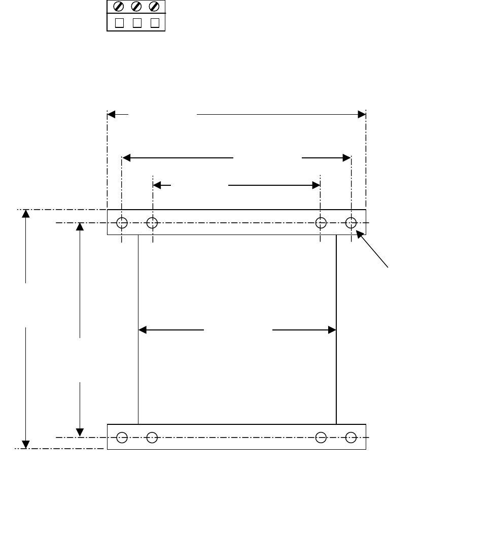
4-7. Receiver Unit Cabinet Mounting.
Mounting hardware is provided. See next page
Figure 4-1A. Installation Hardware. The door is
not attached when the unit is shipped to make it
easier to install the mounting screws. After the
unit is mounted the door should be attached.
Mount receiver unit cabinet securely to mounting
surface. Actual cabinet mounting dimensions and
a mounting template are shown on page 29
Figure 4-2.
4-8. Receiver Installation.
1. Set the Access code per the instructions on
pages xxxx 24-25 Section 7. Servicing and
Programming
2. Position the receiver. Locate as far as
possible from exposed trolley wire and
sources of electromagnetic or radiated noise.
Cabinet mounting dimensions and mounting
template is on page 29 Figure 4-2. Antenna
at top of unit should be kept as clear as
possible of any metal object.
3. Mount the receiver. Through the four deep
mounting holes in corners of the receiver
housing use quantity four #10-24 slotted
round head screws 1” in length, four #10
lock washers and four #10-24 hex nuts.
Lock washers should be used in front of hex
nuts. (Five sets of mounting hardware are
provided; one set is a spare). See Figure 4-
1A. Installation Hardware.
4. Attach door. Put two door screws in door.
(Included in your unit are two pairs of door
screws. One pair slotted and one pair wing
head.) Pick the screws that are preferred,
line up the slots in the door holes with the
tapered part of the screw tip and firmly press
the screws through the holes in the door
until they snap through. (Lightly tapping
them with a hard object will help to snap
them in). Use the special door hinge
screwdriver provided to screw in the door
hinges to the main box. See Figure 4-1A.
Installation Hardware.
5. Wire the unit using the appropriate electrical
drawings for the specific transmitter and
crane orientation selected on pages 17-19
Section 6. – Wiring Diagrams. For crane
orientation determine if the direction pair
Forward or Reverse better describes the
equipment movement. Use this pair to wire
the motor directionals respectively. Make
sure to replace connectors in the correct
locations).
6. Wire the power to J1 input power connector.
The connections are Ground (GND), Neutral
(N) and 120 VAC 50-60 Hz (120V). See
Figure 4-1B. Input Power Connections.
Section 4 – Installation Procedure (Continued)
14
7. Wiring of the system should now be
complete.
8. Stand clear of the crane and apply AC power
to receiver unit. Turn switch SW2 OFF (MR
relay control) and SW1 ON (main power
switch). Check to see if three green LEDs
are lit (DS22, DS23 and DS24). If none are
lit check AC power, power switch SW1 and
fuse.
9. Turn transmitter ON. Check to see if the
yellow LED is now lit (DSMR1). At this
point the MR relay is disabled, the functions
of the transmitter can be checked by noting
the turning ON of the appropriate red LEDs
next to the control relays (DS7 to DS11).
After checking out the functions, turn switch
SW2 ON to enable the MR relay, check
function and direction by jogging each
motion. Now Installation should now be
complete.
10. If there are any problems see pages 20-23
Section 7. – Servicing and Programming.
Figure 4-1. Input Power Connections.
GND N 120V
J1
1
12”
305 mm
11”
280 mm
10”
254 mm
9”
229 mm
7”
179 mm
8”
203 mm
.281” DIA.
7.14 mm
Hole 4 places
Figure 4-2. Receiver Mounting Details
Section 5– Operation
15
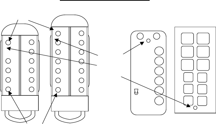
5-1. Transmitter Functions.
ON – (ON/OFF) Turns the transmitter ON and
then sends the ON command to the receiver. (On
Slider ON and OFF button is activated by the
lanyard key. On the Pendant Transmitter ON and
OFF is the same button. On the Pendant the
ON/OFF button turns the unit ON.
OFF – (ON/OFF) Sends the OFF command to
the receiver and then turns the transmitter OFF.
On the Pendant the ON/OFF button turns the unit
OFF.
E-STOP (EMS) – Stops all equipment
movement and disables all functions. Reset the
system for normal operation by turning the
transmitter “OFF” then “ON”. Use for
emergencies only. (NOT FOR NORMAL SHUT
DOWN).
UP (HST UP) – Selects hoist movement in the
UP direction speed one (first switch position) or
speed two (second switch position). For the
Slider the HST UP is pressed and the finger is
slid to the center (2SP) for 2nd speed. The first
direction is maintained while the second speed
key is held.
DN (HST DN and DOWN) – Selects hoist
movement in the DOWN direction speed one
(first switch position) or speed two (second
switch position). For the Slider the HST DN is
pressed and the finger is slid to the center (2SP)
for 2nd speed. The first direction is maintained
while the second speed key is held.
E (FWD, BRIDGE E and EAST) – Selects the
appropriate direction of the bridge or trolley
(depending how unit is wired at installation)
speed one (first switch position) or speed two
(second switch position). For the Slider the
BRIDGE E is pressed and the finger is slid to the
center (2SP). The first direction is maintained
while the second speed key is held for 2nd speed.
W (REV, BRIDGE W and WEST) – Selects
the appropriate direction of the bridge or trolley
(depending how unit is wired at installation)
speed one (first switch position) or speed two
(second switch position). For the Slider the
BRIDGE W is pressed and the finger is slid to
the center (2SP) for 2nd speed. The first direction
is maintained while the second speed key is held.
N (TROLL N and NORTH) – Selects the
appropriate direction of the bridge or trolley
(depending how unit is wired at installation)
speed one (first switch position) or speed two
(second switch position). For the Slider the
UP DN
E W
N S
1 2
3
ON OFF
E
STOP
AUX 1
UP
DOWN
NORTH
SOUTH
EAST
WEST
ON/OFF E-STOP
ON/OFF
LED
Indicator
Figure 5-1. telePilot Pendant and Membrane Transmitters.
ON/OFF
Pushbutton
E-STOP
Section 5 – Operation (Continued)
16 10/19/2001
TROLL N is pressed and the finger is slid to the
center (2SP) for 2nd speed. The first direction is
maintained while the second speed key is held.
S (TROLL S and SOUTH) – Selects the
appropriate direction of the bridge or trolley
(depending how unit is wired at installation)
speed one (first switch position) or speed two
(second switch position). For the Slider the
TROLL S is pressed and the finger is slid to the
center (2SP) for 2nd speed. The first direction is
maintained while the second speed key is held.
1, 2 and 3 (AUX 1, AUX 2, and AUX 3) –
Selects the Auxiliary relay(s), which may be
used for a warning device as a horn or other
function.
5-2. Transmitter LED Indicator.
When the transmitter is ON the red LED flashes
slowly. When the unit transmits, the red LED
flashes rapidly.
If there is no LED indicator at all after turning
ON the transmitter or while operating crane with
the transmitter, replace the batteries, they are
weak. See Section 5-4. Battery Replacement on
this page for battery replacement.
5-3. Operation.
WARNING
BEFORE TURNING ON OR OPERATING
THE CRANE, MAKE SURE ALL
PERSONNEL ARE CLEAR OF THE
OPERATING AREA AND NO ONE IS
STANDING UNDER THE LOAD. FAILURE
TO FOLLOW THIS WARNING COULD
RESULT IN SERIOUS INJURY OR DEATH
AND DAMAGE TO EQUIPMENT.
WARNING
WHEN OPERATING THE CRANE FOLLOW
LOCAL AND GOVERNMENTAL RULES ON
THE USE OF HORNS AND ALARMS.
FAILURE TO FOLLOW THIS WARNING
COULD RESULT IN SERIOUS INJURY OR
DEATH AND DAMAGE TO EQUIPMENT.
Make sure that all personnel are clear of the
crane movement and no one is under the crane or
load.
Turn unit ON by pressing the ON (ON/OFF)
button. The red LED should flash rapidly for a
few seconds indicating the ON command is
being sent to the receiver. After the receiver is
turned ON the red LED should flash slowly
indicating the transmitter is now ready to send
commands.
Perform whatever safety checks are required. See
Section 2. Radio Controlled Safety. Operate any
horns or alarms as required by local and
governmental regulations.
To operate the crane, press and hold the desired
function button to maintain operation. Press the
directional buttons harder to second position to
engage second speed for those cranes having
two-speed motors.
Always turn system OFF by pressing the OFF
(ON/OFF) button on the transmitter when done
with crane operation.
In an emergency always hit E-STOP (EMS)
immediately. To clear the emergency condition,
turn the transmitter OFF and ON again to resume
normal operation.
The receiver will time-out after approximately
15 minutes if there is no activity. The transmitter
is programmed to time-out if not used for 15
minutes also.
WARNING
IN AN EMERGENCY HIT “E-STOP” TO
STOP ALL CRANE MOVEMENT. WHEN
EMERGENCY HAS CLEARED TURN THE
TRANSMITTER OFF THEN ON AGAIN TO
RESUME NORMAL OPERATION. FAILURE
TO FOLLOW THIS WARNING COULD
RESULT IN SERIOUS INJURY OR DEATH
AND DAMAGE TO EQUIPMENT.
5-4. Battery Replacement.

Section 5 – Operation (Continued)
17 10/19/2001
To replace the batteries, turn transmitter over to
access back cover. Twist half moon shaped
battery latch to remove cover. Take out old
batteries; replace ALL batteries with new cells.
For the Membrane Transmitter note battery
orientation, batteries in backwards will blow
fuse. Replace cover and turn transmitter ON to
use. See Section 9. Spare Parts for battery and
fuse part numbers.

Section 6 – Wiring
18
6-1. Wiring Diagrams.
The following pages in this section have
individual wiring diagrams for different crane
configurations. Find the appropriate wiring
diagram and set the Configuration Switch (SW3
in the receiver) in the appropriate receiver(s) to
match the SW3 Receiver Configuration Switch
settings shown in the diagram. The location of
the Configuration Switch is shown in Figure 8-1.
Receiver Layout. Terminal designators are
marked on the wiring diagram corresponding to
designators found on the Receiver Board. For
terminal locations see Figure 8-1. Receiver
Layout. The proper connections to use for the
bridge and for the trolley are best determined by
that pair of directional designators (North/South
or East/West) best describes the crane’s
movement. Does the bridge travel East/West or
North/South? The trolley would use the other
directional pair as the bridge. Care should be
taken after a directional pair is selected to make
sure the specific motor directional inputs match
the desired direction of the bridge or trolley, i.e.,
if North/South is picked for the bridge make sure
the South traveling bridge motor directional is
wired to the South terminal of the unit.
Typically in the following wiring diagrams, the
bridge is shown as E/W (East/West) and Trolley
as N/S (North/South). Since the labeling cannot
be easily moved on the Membrane Transmitter
keypad, the two directional pairs can be easily
exchanged by turning the dipswitch SW3
position 1 in the Membrane Transmitter to
“ON”. See Section 8-2.6. Repositioning of
Membrane Transmitter Motion Switch Functions
for more details.
6-2. Installation.
Follow Section 4. Installation Information for
instructions on how to install the receiver.
6-3. Alarms and Horns.
Make sure that the installation includes the
proper alarms, horns, indicator lights and their
associated controls as required by local and
governmental regulations.
6-4. Membrane Transmitter Wiring.
The wiring diagrams output connections shown
in the following pages match the nomenclature
on the single and Two-Speed Membrane per
their respective diagrams.
6-5. Single-Speed Pendant Transmitter
Wiring.
For the Single-Speed Pendant Transmitter the
only wiring configuration is the diagram in
Figure 6-9. 10K6 Single Receiver with Single-
Speed Pendant, Single-Speed Bridge, Trolley
and Hoist.
6-6. Two-Speed Pendant Transmitter Wiring.
For the Two-Speed 10K12 Pendant Transmitter
the functional labeling is different than the Two-
Speed Membrane. E/W and N/S are exchanged.
By setting dipswitch SW3 position 1 in the “ON”
position the pushbuttons of the Pendant
Transmitter match the directional notations on
the two-speed wiring diagrams in Section 6.
Wiring. Failure to turn switch SW3 position 1 to
“ON” will cause EAST/WEST and
NORTH/SOUTH to be exchanged respectively.
All other functions will remain the same.
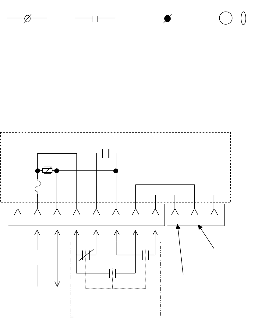
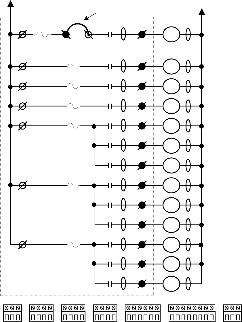
6-7. Relay Sequencing
When the second speed position is activated the
appropriate directional relay is still engaged.
6-8. Connecting Outputs to Drives.
MOV’s (transient protectors) are on all the
output relays to protect the relays from power
surges. MOV’s allow a small leakage current
that can affect some high impedance circuits.
When connecting output relays to drives, it may
be required to remove the MOV to prevent the
leakage current through the MOV from holding
in the drive. See Figure 8-1. Receiver Layout for
the location of the MOV's. The MOV’s are
numbered correspondingly to the relays they
protect. The MOV’s can be cut out of the circuit
with a wire cutter. Remember to do this with
ALL power OFF on the crane and all associated
controls.
Section 6 – Wiring (Continued)
19 10/19/2001
Legend
The following is the legend for the wiring
diagrams below:
6-9. Optional Transfer Switch Wiring
Configuration.
If a transfer switch is desired, the additional
connectors on the board facilitate the wiring of a
transfer switch. The schematic of the transfer
switch interface is shown for reference.
Matching relay contacts
in radio receiver panel
by number.
#
An input with the terminal
number # matching the con-
nector in the receiver.
#
An output with the terminal
number # matching the con-
nector in the receiver.
Customer supplied
contactor coil with arc
suppressor in parallel.
C#
K#
Figure 6-1. Legend.
Optional Transfer Switch
(2-pole double-throw)
To Main
Line
Contactor
Switched Power
From Hardwired
Pendant To Main
Line Contactor
Figure 6-2. Optional Transfer Switch Wiring
J6-1 J6-2 J6-3 J6-4 J6-5 J6-6 J6-7 J6-8 J7-1 J7-2 J7-3
Power To
Hardwired
Pendant
HOT
K13 MR
MOV
Fuse
Receiver Panel
N/C N/C
Section 6 - Wiring (Continued)
20
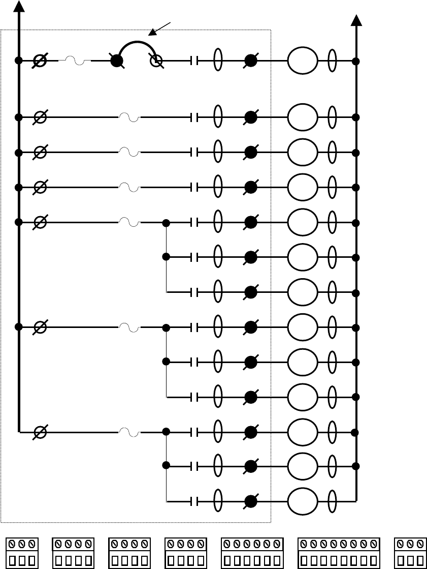
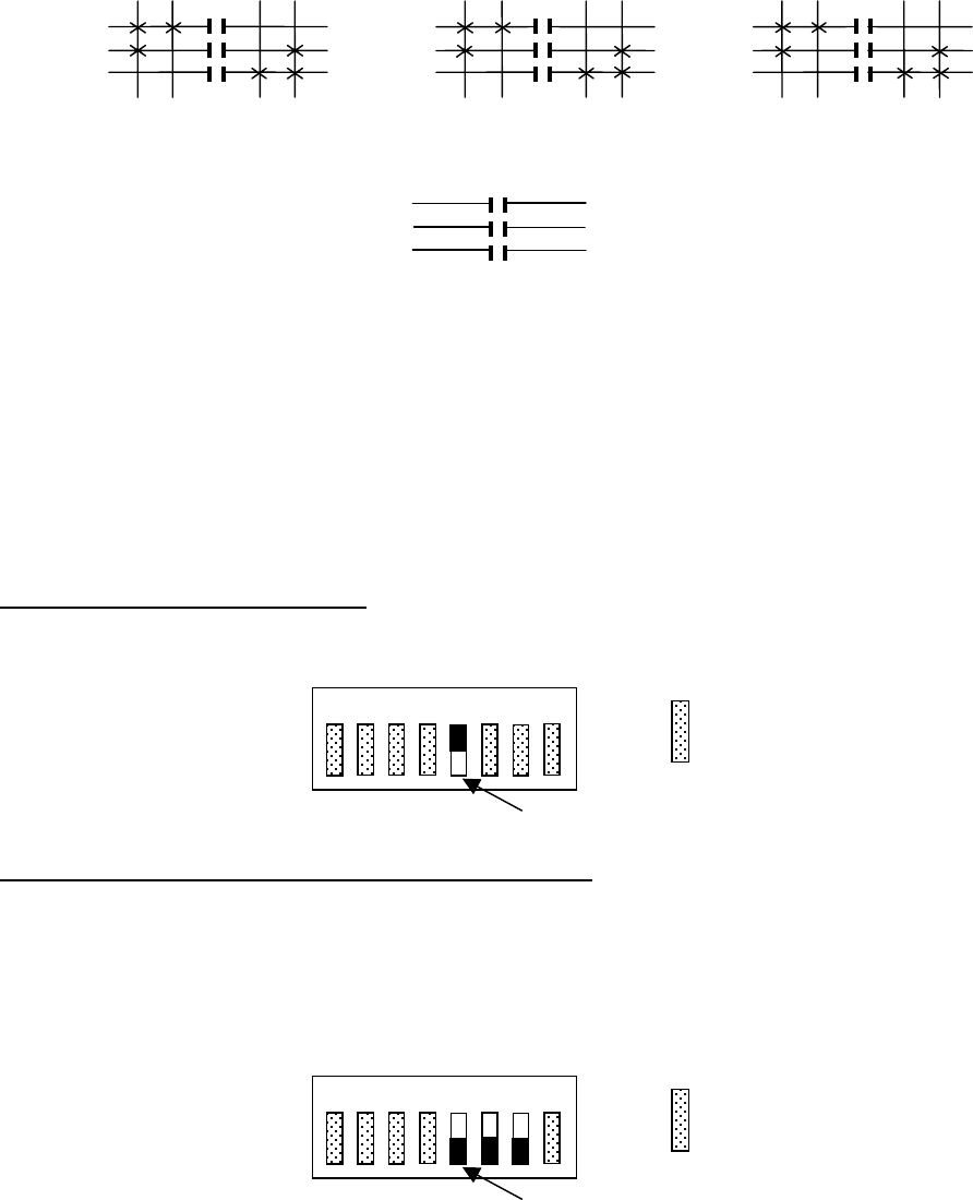
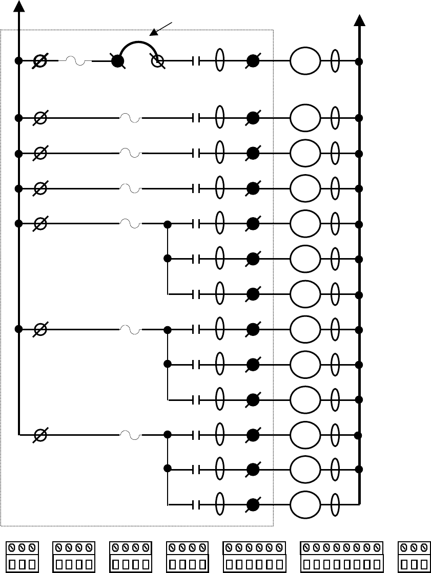
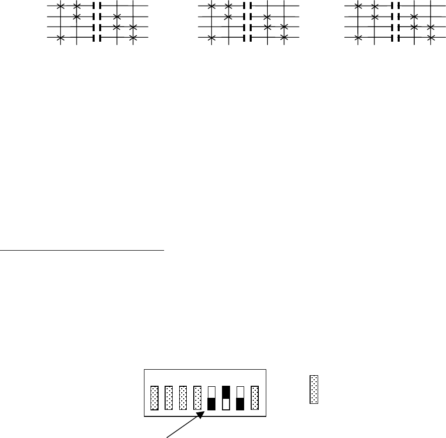
TABLE 1 TR12 SINGLE SPEED WIRING DIAGRAM.
STANDARD CONFIGURATION HOIST, TROLLEY AND BRIDGE
MASTER
RELAY
MAIN LINE
CONTACTOR
AUX 5
ALARM
AUX 6
(latchable S4-3)
AUX 4
(latchable S4-2)
MOTOR 1 (M1)
(M1) DIR 1
AUX 3
(M1) DIR 2
MOTOR 2 (M2)
(M2) DIR 1
AUX 2
(M2) DIR 2
MOTOR 3 (M3)
(M3) DIR 1
AUX 1
(M3) DIR 2
Receiver Panel
J6-2
J5-5
J5-3
J5-1
J4-4
J3-4
J2-4
J6-3
J5-6
J5-4
J5-2
J4-3
J4-2
J4-1
J3-3
J3-2
J3-1
J2-3
J2-2
J2-1
HOT RETURN
K13
K12
K11
K10
K9
K8
K7
K6
K5
K4
K3
K2
K1
MLC
C12
C11
C10
C9
C8
C7
C6
C5
C4
C3
C2
C1
F7
F6
F5
F4
F3
F2
J7-3
J7-2
J7-1
J6-8
J6-7
J6-6
J6-5
J6-4
J6-3
J6-2
J6-1
J5-6
J5-5
J5-4
J5-3
J5-2
J5-1
J4-4
J4-3
J4-2
J4-1
J3-4
J3-3
J3-2
J3-1
J2-4
J2-3
J2-2
J2-1
J1-3
J1-2
J1-1
External jumper
in J6 connector
J6-4 J6-5
F8
Section 6 - Wiring (Continued)
21
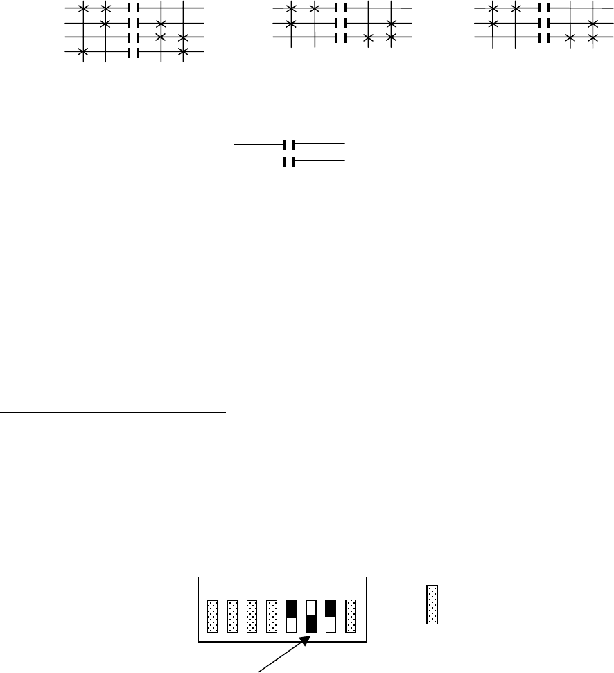
TABLE 1 TR12 SINGLE SPEED PROGRAMMING DIAGRAM.
STANDARD CONFIGURATION HOIST, TROLLEY AND BRIDGE
MOTOR 1 CONNECTIONS MOTOR 2 CONNECTIONS MOTOR 3 CONNECTIONS
J4-3 HOIST UP J3-3 TROLLEY DIR 1 J2-3 BRIDGE DIR 1
J4-2 AUX 3 J3-2 AUX 2 J2-2 AUX 1
J4-1 HOIST DOWN J3-1 TROLLEY DIR 2 J2-1 BRIDGE DIR 2
J4-4 HOT (J4-1, 2 & 3) J3-4 HOT (J3-1, 2 & 3) J2-4 HOT (J2-1, 2 & 3)
INDEPENDENT CONNECTIONS
J5-2 AUX 4 (LATCHABLE S4-2) J5-1 HOT AUX 4
J5-4 AUX 6 (LATCHABLE S4-3) J5-3 HOT AUX 6
J5-6 AUX 5 ALARM J5-5 HOT AUX 5
TRANSMITTER SWITCH SETTINGS
telePilot USE PDA SCREEN (Program the configuration switches 5, 6 & 7 to match the settings
shown below).
MEMBRANE USE SW3 “C”
PENDANT, JLTX AND SLTX USE SW4 “D”
TRANSMITTER SWITCH SETTINGS: Position-5 Position -6 Position -7
OFF OFF OFF
*NOTE: Hoist, Trolley and Bridge are listed here as traditional configurations, the
installer may choose to define the motors differently.
OFF
1 2 3 4 5 6 7 8 ON
For these switch
positions see
previous section.
Indicates Switch in OFF Position.
OUTPUTS
J2-3
J2-1
BRIDGE*
MOTOR 3 1ST
Dir 1 Dir 2
OUTPUTS
J4-3
J4-1
HOIST*
MOTOR 1 1ST
UP DN
1ST 1ST
J2-2
J3-2
J4-2
AUX 1
AUX 2
AUX 3
INDEPENDENT OUTPUTS
OUTPUTS
J3-3
J3-1
TROLLEY*
MOTOR 2 1ST
Dir 1 Dir 2
1ST
J5-2
J5-6
J5-4
AUX 4
AUX 5
AUX 6

Section 6 - Wiring (Continued)
22
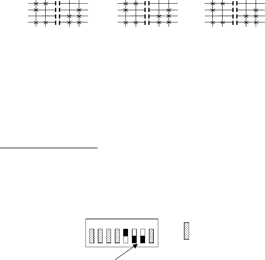
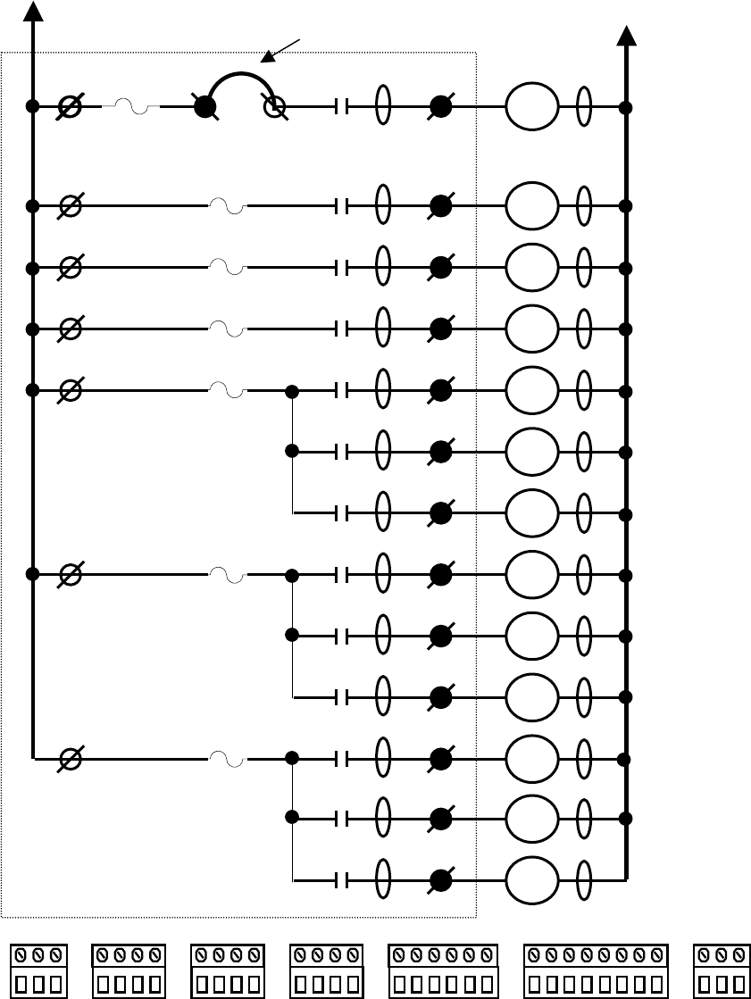
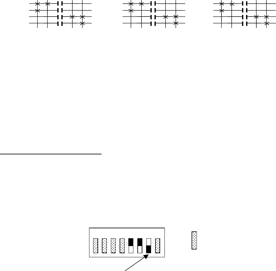
TABLE 2(A) TR12 2-SPEED WIRING DIAGRAM.
STANDARD CONFIGURATION HOIST, TROLLEY AND BRIDGE
MASTER
RELAY
MAIN LINE
CONTACTOR
AUX 3
ALARM
AUX 2
(latchable S4-3)
AUX 1
(latchable S4-2)
MOTOR 1 (M1)
(M1) DIR 1
(M1) 2ND SPD
(M1) DIR 2
MOTOR 2 (M2)
(M2) DIR 1
(M2) 2ND SPD
(M2) DIR 2
MOTOR 3 (M3)
(M3) DIR 1
(M3) 2ND SPD
(M3) DIR 2
Receiver Panel
J6-2
J5-5
J5-3
J5-1
J4-4
J3-4
J2-4
J6-3
J5-6
J5-4
J5-2
J4-3
J4-2
J4-1
J3-3
J3-2
J3-1
J2-3
J2-2
J2-1
HOT RETURN
K13
K12
K11
K10
K9
K8
K7
K6
K5
K4
K3
K2
K1
MLC
C12
C11
C10
C9
C8
C7
C6
C5
C4
C3
C2
C1
F7
F6
F5
F4
F3
F2
J7-3
J7-2
J7-1
J6-8
J6-7
J6-6
J6-5
J6-4
J6-3
J6-2
J6-1
J5-6
J5-5
J5-4
J5-3
J5-2
J5-1
J4-4
J4-3
J4-2
J4-1
J3-4
J3-3
J3-2
J3-1
J2-4
J2-3
J2-2
J2-1
J1-3
J1-2
J1-1
External jumper
in J6 connector
J6-4 J6-5
F8
Section 6 - Wiring (Continued)
23
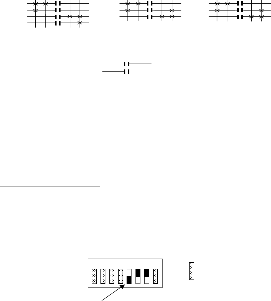
TABLE 2(A) TR12 2-SPEED PROGRAMMING DIAGRAM.
STANDARD CONFIGURATION HOIST, TROLLEY AND BRIDGE
MOTOR 1 CONNECTIONS MOTOR 2 CONNECTIONS MOTOR 3 CONNECTIONS
J4-3 HOIST UP J3-3 TROLLEY DIR 1 J2-3 BRIDGE DIR 1
J4-2 HOIST 2ND SPEED J3-2 TROLLEY 2ND SPEED J2-2 BRIDGE 2ND SPEED
J4-1 HOIST DOWN J3-1 TROLLEY DIR 2 J2-1 BRIDGE DIR 2
J4-4 HOT (J4-1, 2 & 3) J3-4 HOT (J3-1, 2 & 3) J2-4 HOT (J2-1, 2 & 3)
INDEPENDENT CONNECTIONS
J5-2 AUX 1 (LATCHABLE S4-2) J5-1 HOT AUX 1
J5-4 AUX 2 (LATCHABLE S4-3) J5-3 HOT AUX 2
J5-6 AUX 3 ALARM J5-5 HOT AUX 3 ALARM
RECEIVER SWITCH SETTINGS SW3: SW3 Position-5
ON
SINGLE SPEED ONLY TRANSMITTERS SWITCH SETTINGS
SINGLE SPEED telePilot USE PDA SCREEN (select single speed transmitter style).
SINGLE SPEED MEMBRANE USE SW3 “C”, SINGLE SPEED PENDANT USE SW “D”
TRANSMITTER SWITCH SETTINGS: Position-5 Position -6 Position -7
OFF OFF OFF
*NOTE: Hoist, Trolley and Bridge are listed here as traditional configurations, the installer may choose to define the
motors differently.
OFF
1 2 3 4 5 6 7 8 ON
For these switch
positions see
previous section.
Indicates Switch in OFF Position.
OUTPUTS
J2-3
J2-2
J2-1
BRIDGE*
MOTOR 3 1ST 2ND
Dir 1 Dir 2
OUTPUTS
J4-3
J4-2
J4-1
HOIST*
MOTOR 1 1ST 2ND
UP DN
2ND 1ST 2ND 1ST
J5-2
J5-4
J5-6
AUX 1
AUX 2
AUX 3 ALARM
INDEPENDENT OUTPUTS
OUTPUTS
J3-3
J3-2
J3-1
TROLLEY*
MOTOR 2 1ST 2ND
Dir 1 Dir 2
2ND 1ST
OFF
1 2 3 4 5 6 7 8 ON
For these switch
positions see
previous section.
Indicates Switch in ON Position.
Section 6 - Wiring (Continued)
24
TABLE 2(B) TR12 2-SPEED WIRING DIAGRAM.
2-SPEED with DIRECTIONAL CONTROLS: ALL MOTIONS
MASTER
RELAY
MAIN LINE
CONTACTOR
MOTOR 1
DIR1/DIR2
MOTOR 2
DIR1/DIR2
MOTOR 3
DIR1/DIR2
MOTOR 1 (M1)
(M1) DIR 1
(M1) 2ND SPD
(M1) DIR 2
MOTOR 2 (M2)
(M2) DIR1
(M2) 2ND SPD
(M2) DIR 2
MOTOR 3 (M3)
(M3) DIR 1
(M3) 2ND SPD
(M3) DIR 2
Receiver Panel
J6-2
J5-5
J5-3
J5-1
J4-4
J3-4
J2-4
J6-3
J5-6
J5-4
J5-2
J4-3
J4-2
J4-1
J3-3
J3-2
J3-1
J2-3
J2-2
J2-1
HOT RETURN
K13
K12
K11
K10
K9
K8
K7
K6
K5
K4
K3
K2
K1
MLC
C12
C11
C10
C9
C8
C7
C6
C5
C4
C3
C2
C1
F7
F6
F5
F4
F3
F2
J7-3
J7-2
J7-1
J6-8
J6-7
J6-6
J6-5
J6-4
J6-3
J6-2
J6-1
J5-6
J5-5
J5-4
J5-3
J5-2
J5-1
J4-4
J4-3
J4-2
J4-1
J3-4
J3-3
J3-2
J3-1
J2-4
J2-3
J2-2
J2-1
J1-3
J1-2
J1-1
External jumper
in J6 connector
J6-4 J6-5
F8
Section 6 - Wiring (Continued)
25
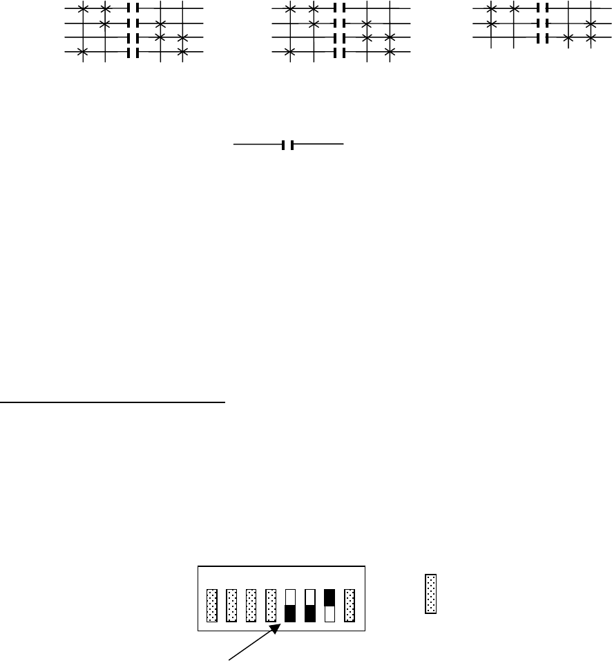
TABLE 2(B) TR12 2-SPEED PROGRAMMING DIAGRAM.
2-SPEED with DIRECTIONAL CONTROLS: ALL MOTIONS
MOTOR 1 CONNECTIONS MOTOR 2 CONNECTIONS MOTOR 3 CONNECTIONS
J4-3 HOIST UP J3-3 TROLLEY DIR 1 J2-3 BRIDGE DIR 1
J4-2 HOIST 2ND SPEED J3-2 TROLLEY 2ND SPEED J2-2 BRIDGE 2ND SPEED
J4-1 HOIST DOWN J3-1 TROLLEY DIR 2 J2-1 BRIDGE DIR 2
J4-4 HOT (J4-1, 2 & 3) J3-4 HOT (J3-1, 2 & 3) J2-4 HOT (J2-1, 2 & 3)
J5-6 HOIST DIR1/DIR2 J5-4 TROLLEY DIR1/DIR2 J5-2 BRIDGE DIR1/DIR2
J5-5 HOT HOIST DIR1/DIR2 J5-3 HOT TROLLEY DIR1/DIR2 J5-1 HOT BRIDGE DIR1/DIR2
NOTE
CHECK GOVERNMENTAL AND LOCAL REGULATIONS ON THE REQUIREMENTS OF HORNS OR ALARMS
BEFORE USING THIS CONFIGURATION, AS THERE IS NOT A SEPARATE ALARM CONTROL.
TRANSMITTER SWITCH SETTINGS
telePilot USE PDA SCREEN (Program the configuration switches 5, 6 & 7 to match the settings shown below).
MEMBRANE USE SW3 “C”
PENDANT, JLTX AND SLTX USE SW4 “D”
TRANSMITTER SWITCH SETTINGS: Position-5 Position -6 Position -7
ON OFF OFF
*NOTE: Hoist, Trolley and Bridge are listed here as traditional configurations, the installer may choose to define the
motors differently.
OFF
1 2 3 4 5 6 7 8 ON
For these switch
positions see
previous section.
Indicates Switch in OFF Position.
OUTPUTS
J2-3
J2-2
J2-1
BRIDGE*
MOTOR 3 1ST 2ND
Dir 1 Dir 2
OUTPUTS
J4-3
J4-2
J4-1
HOIST*
MOTOR 1 1ST 2ND
UP DN
2ND 1ST 2ND 1ST
OUTPUTS
J3-3
J3-2
J3-1
TROLLEY*
MOTOR 2 1ST 2ND
Dir 1 Dir 2
2ND 1ST
J5-2
J5-6 J5-4
Section 6 - Wiring (Continued)
26
TABLE 1(C) TR12 WIRING DIAGRAM.
2-SPEED, 2-WINDINGS: ALL MOTIONS
MASTER
RELAY
MAIN LINE
CONTACTOR
MOTOR 1
2ND SPD
MOTOR 2
2ND SPD
MOTOR 3
2ND SPD
MOTOR 1 (M1)
(M1) DIR 1
(M1) 1ST SPD
(M1) DIR 2
MOTOR 2 (M2)
(M2) DIR 1
(M2) 1ST SPD
(M2) DIR 2
MOTOR 3 (M3)
(M3) DIR 1
(M3) 1ST SPD
(M3) DIR 2
Receiver Panel
J6-2
J5-5
J5-3
J5-1
J4-4
J3-4
J2-4
J6-3
J5-6
J5-4
J5-2
J4-3
J4-2
J4-1
J3-3
J3-2
J3-1
J2-3
J2-2
J2-1
HOT RETURN
K13
K12
K11
K10
K9
K8
K7
K6
K5
K4
K3
K2
K1
MLC
C12
C11
C10
C9
C8
C7
C6
C5
C4
C3
C2
C1
F7
F6
F5
F4
F3
F2
J7-3
J7-2
J7-1
J6-8
J6-7
J6-6
J6-5
J6-4
J6-3
J6-2
J6-1
J5-6
J5-5
J5-4
J5-3
J5-2
J5-1
J4-4
J4-3
J4-2
J4-1
J3-4
J3-3
J3-2
J3-1
J2-4
J2-3
J2-2
J2-1
J1-3
J1-2
J1-1
External jumper
in J6 connector
J6-4 J6-5
F8
Section 6 - Wiring (Continued)
27
TABLE 2(C) TR12 2-SPEED PROGRAMMING DIAGRAM.
2-SPEED, 2-WINDINGS: ALL MOTIONS
MOTOR 1 CONNECTIONS MOTOR 2 CONNECTIONS MOTOR 3 CONNECTIONS
J4-3 HOIST UP J3-3 TROLLEY DIR 1 J2-3 BRIDGE DIR 1
J4-2 HOIST 1 ST SPEED J3-2 TROLLEY 1 ST SPEED J2-2 BRIDGE 1 ST SPEED
J4-1 HOIST DOWN J3-1 TROLLEY DIR 2 J2-1 BRIDGE DIR 2
J4-4 HOT (J4-1, 2 & 3) J3-4 HOT (J3-1, 2 & 3) J2-4 HOT (J2-1, 2 & 3)
J5-6 HOIST 2ND SPEED J5-4 TROLLEY 2ND SPEED J5-2 BRIDGE 2ND SPEED
J5-5 HOT HOIST 2ND SPEED J5-3 HOT TROLLEY 2ND SPEED J5-1 HOT BRIDGE 2ND SPEED
NOTE
CHECK GOVERNMENTAL AND LOCAL REGULATIONS ON THE REQUIREMENTS OF HORNS OR ALARMS
BEFORE USING THIS CONFIGURATION, AS THERE IS NOT A SEPARATE ALARM CONTROL.
TRANSMITTER SWITCH SETTINGS
telePilot USE PDA SCREEN (Program the configuration switches to match the pattern and position shown).
MEMBRANE USE SW3 “C”
PENDANT, JLTX AND SLTX USE SW4 “D”
TRANSMITTER SWITCH SETTINGS: Position-5 Position -6 Position -7
OFF ON OFF
*NOTE: Hoist, Trolley and Bridge are listed here as traditional configurations, the installer may choose to define the
motors differently.
OFF
1 2 3 4 5 6 7 8 ON
For these switch
positions see
previous section.
Indicates Switch in OFF Position.
OUTPUTS
J2-3
J2-2
J2-1
BRIDGE*
MOTOR 3 1ST 2ND
Dir 1 Dir 2
OUTPUTS
J4-3
J4-2
J4-1
HOIST*
MOTOR 1 1ST 2ND
UP DN
2ND 1ST 2ND 1ST
OUTPUTS
J3-3
J3-2
J3-1
TROLLEY*
MOTOR 2 1ST 2ND
Dir 1 Dir 2
2ND 1ST
J5-2
J5-6 J5-4

Section 6 - Wiring (Continued)
28
TABLE 1(D) TR12 WIRING DIAGRAM.
ACCO CONTROLS: ALL MOTIONS
MASTER
RELAY
MAIN LINE
CONTACTOR
MOTOR 1
2ND SPD DIR 2
MOTOR 2
2ND SPD DIR 2
MOTOR 3
2ND SPD DIR 2
MOTOR 1 (M1)
(M1) DIR 1
(M1) 2ND SPD
DIR 1
(M1) DIR 2
MOTOR 2 (M2)
(M2) DIR 1
(M2) 2ND SPD
DIR 1
(M2) DIR 2
MOTOR 1 (M3)
(M3) DIR 1
(M3) 2ND SPD
DIR 1
(M3) DIR 2
Receiver Panel
J6-2
J5-5
J5-3
J5-1
J4-4
J3-4
J2-4
J6-3
J5-6
J5-4
J5-2
J4-3
J4-2
J4-1
J3-3
J3-2
J3-1
J2-3
J2-2
J2-1
HOT RETURN
K13
K12
K11
K10
K9
K8
K7
K6
K5
K4
K3
K2
K1
MLC
C12
C11
C10
C9
C8
C7
C6
C5
C4
C3
C2
C1
F7
F6
F5
F4
F3
F2
J7-3
J7-2
J7-1
J6-8
J6-7
J6-6
J6-5
J6-4
J6-3
J6-2
J6-1
J5-6
J5-5
J5-4
J5-3
J5-2
J5-1
J4-4
J4-3
J4-2
J4-1
J3-4
J3-3
J3-2
J3-1
J2-4
J2-3
J2-2
J2-1
J1-3
J1-2
J1-1
External jumper
in J6 connector
J6-4 J6-5
F8
Section 6 - Wiring (Continued)
29
TABLE 2(D) TR12 2-SPEED PROGRAMMING DIAGRAM.
ACCO CONTROLS: ALL MOTIONS
MOTOR 1 CONNECTIONS MOTOR 2 CONNECTIONS MOTOR 3 CONNECTIONS
J4-3 HOIST UP J3-3 TROLLEY DIR 1 J2-3 BRIDGE DIR 1
J4-2 HOIST 2ND SPEED DIR 1 J3-2 TROLLEY 2ND SPEED DIR 1 J2-2 BRIDGE 2ND SPEED DIR 1
J4-1 HOIST DOWN J3-1 TROLLEY DIR 2 J2-1 BRIDGE DIR 2
J4-4 HOT (J4-1, 2 & 3) J3-4 HOT (J3-1, 2 & 3) J2-4 HOT (J2-1, 2 & 3)
J5-6 HOIST 2ND SPEED DIR 2 J5-4 TROLLEY 2ND SPEED DIR 2 J5-2 BRIDGE 2ND SPEED DIR 2
J5-5 HOT HOIST 2ND SPD DIR 2 J5-3 HOT TROLLEY 2ND SPD DIR 2 J5-1 HOT BRIDGE 2ND SPD DIR 2
NOTE
CHECK GOVERNMENTAL AND LOCAL REGULATIONS ON THE REQUIREMENTS OF HORNS OR ALARMS
BEFORE USING THIS CONFIGURATION, AS THERE IS NOT A SEPARATE ALARM CONTROL.
TRANSMITTER SWITCH SETTINGS
telePilot USE PDA SCREEN (Program the configuration switches 5, 6 & 7 to match the settings shown below).
MEMBRANE USE SW3 “C”
PENDANT, JLTX AND SLTX USE SW4 “D”
TRANSMITTER SWITCH SETTINGS: Position-5 Position -6 Position -7
ON ON OFF
*NOTE: Hoist, Trolley and Bridge are listed here as traditional configurations, the installer may choose to define the
motors differently.
OFF
1 2 3 4 5 6 7 8 ON
For these switch
positions see
previous section.
Indicates Switch in OFF Position.
OUTPUTS
J2-3
J2-2
J2-1
BRIDGE*
MOTOR 3 1ST 2ND
Dir 1 Dir 2
OUTPUTS
J4-3
J4-2
J4-1
HOIST*
MOTOR 1 1ST 2ND
UP DN
2ND 1ST 2ND 1ST
OUTPUTS
J3-3
J3-2
J3-1
TROLLEY*
MOTOR 2 1ST 2ND
Dir 1 Dir 2
2ND 1ST
J5-2
J5-6 J5-4

Section 6 - Wiring (Continued)
30
TABLE 1(E) TR12 WIRING DIAGRAM.
P&H: 2-SPEED, 2-WINDINGS for HOIST and TROLLEY;
STANDARD BRIDGE
MASTER
RELAY
MAIN LINE
CONTACTOR
MOTOR 1
2ND SPD
MOTOR 2
2ND SPD
AUX 1
(latchable S4-2)
MOTOR 1 (M1)
(M1) DIR 1
(M1) 2ND SPD
(M1) DIR 2
MOTOR 2 (M2)
(M2) DIR 1
(M2) 1ST SPD
(M2) DIR 2
MOTOR 3 (M3)
(M3) DIR 1
(M3) 1ST SPD
(M3) DIR 2
Receiver Panel
J6-2
J5-5
J5-3
J5-1
J4-4
J3-4
J2-4
J6-3
J5-6
J5-4
J5-2
J4-3
J4-2
J4-1
J3-3
J3-2
J3-1
J2-3
J2-2
J2-1
HOT RETURN
K13
K12
K11
K10
K9
K8
K7
K6
K5
K4
K3
K2
K1
MLC
C12
C11
C10
C9
C8
C7
C6
C5
C4
C3
C2
C1
F7
F6
F5
F4
F3
F2
J7-3
J7-2
J7-1
J6-8
J6-7
J6-6
J6-5
J6-4
J6-3
J6-2
J6-1
J5-6
J5-5
J5-4
J5-3
J5-2
J5-1
J4-4
J4-3
J4-2
J4-1
J3-4
J3-3
J3-2
J3-1
J2-4
J2-3
J2-2
J2-1
J1-3
J1-2
J1-1
External jumper
in J6 connector
J6-4 J6-5
F8
Section 6 - Wiring (Continued)
31
TABLE 2(E) TR12 2-SPEED PROGRAMMING DIAGRAM.
P&H: 2-SPEED, 2-WINDINGS for HOIST and TROLLEY;
STANDARD BRIDGE
MOTOR 1 CONNECTIONS MOTOR 2 CONNECTIONS MOTOR 3 CONNECTIONS
J4-3 HOIST UP J3-3 TROLLEY DIR 1 J2-3 BRIDGE DIR 1
J4-2 HOIST 1ST SPEED J3-2 TROLLEY 1ST SPEED J2-2 BRIDGE 2ND SPEED
J4-1 HOIST DOWN J3-1 TROLLEY DIR 2 J2-1 BRIDGE DIR 2
J4-4 HOT (J4-1, 2 & 3) J3-4 HOT (J3-1, 2 & 3) J2-4 HOT (J2-1, 2 & 3)
J5-6 HOIST 2ND SPEED J5-4 TROLLEY 2ND SPEED
J5-5 HOT HOIST 2ND SPEED J5-3 HOT TROLLEY 2ND SPEED
INDEPENDENT CONNECTIONS
J5-2 AUX 1 (LATCHABLE S4-2) J5-1 HOT AUX 1
TRANSMITTER SWITCH SETTINGS
telePilot USE PDA SCREEN (Program the configuration switches 5, 6 & 7 to match the settings shown below).
MEMBRANE USE SW3 “C”
PENDANT, JLTX AND SLTX USE SW4 “D”
TRANSMITTER SWITCH SETTINGS: Position-5 Position -6 Position -7
OFF OFF ON
*NOTE: Hoist, Trolley and Bridge are listed here as traditional configurations, the installer may choose to define the
motors differently.
OFF
1 2 3 4 5 6 7 8 ON
For these switch
positions see
previous section.
Indicates Switch in OFF Position.
OUTPUTS
J2-3
J2-2
J2-1
BRIDGE*
MOTOR 3
1ST 2ND
Dir 1 Dir 2
OUTPUTS
J4-3
J4-2
J4-1
HOIST*
MOTOR 1 1ST 2ND
UP DN
2ND 1ST
2ND 1ST
OUTPUTS
J3-3
J3-2
J3-1
TROLLEY*
MOTOR 2 1ST 2ND
Dir 1 Dir 2
2ND 1ST
J5-6 J5-4
J5-2 AUX 1
INDEPENDENT OUTPUTS
Section 6 - Wiring (Continued)
32
TABLE 1(F) TR12 WIRING DIAGRAM.
P&H: 2-SPEED, 2-WINDINGS for HOIST;
STANDARD TROLLEY and BRIDGE
MASTER
RELAY
MAIN LINE
CONTACTOR
MOTOR 1
2ND SPD
AUX 2
(latchable S4-3)
AUX 1
(latchable S4-2)
MOTOR 3 (M1)
(M1) DIR 1
(M1) 2ND SPD
(M1) DIR 2
MOTOR 2 (M2)
(M2) DIR 1
(M2) 2ND SPD
(M2) DIR 2
MOTOR 1 (M3)
(M3) DIR 1
(M3) 1ST SPD
(M3) DIR 2
Receiver Panel
J6-2
J5-5
J5-3
J5-1
J4-4
J3-4
J2-4
J6-3
J5-6
J5-4
J5-2
J4-3
J4-2
J4-1
J3-3
J3-2
J3-1
J2-3
J2-2
J2-1
HOT RETURN
K13
K12
K11
K10
K9
K8
K7
K6
K5
K4
K3
K2
K1
MLC
C12
C11
C10
C9
C8
C7
C6
C5
C4
C3
C2
C1
F7
F6
F5
F4
F3
F2
J7-3
J7-2
J7-1
J6-8
J6-7
J6-6
J6-5
J6-4
J6-3
J6-2
J6-1
J5-6
J5-5
J5-4
J5-3
J5-2
J5-1
J4-4
J4-3
J4-2
J4-1
J3-4
J3-3
J3-2
J3-1
J2-4
J2-3
J2-2
J2-1
J1-3
J1-2
J1-1
External jumper
in J6 connector
J6-4 J6-5
F8
Section 6 - Wiring (Continued)
33
TABLE 2(F) TR12 2-SPEED PROGRAMMING DIAGRAM.
P&H: 2-SPEED, 2-WINDINGS for HOIST;
STANDARD TROLLEY and BRIDGE
MOTOR 1 CONNECTIONS MOTOR 2 CONNECTIONS MOTOR 3 CONNECTIONS
J4-3 HOIST UP J3-3 TROLLEY DIR 1 J2-3 BRIDGE DIR 1
J4-2 HOIST 1ST SPEED J3-2 TROLLEY 2ND SPEED J2-2 BRIDGE 2ND SPEED
J4-1 HOIST DOWN J3-1 TROLLEY DIR 2 J2-1 BRIDGE DIR 2
J4-4 HOT (J4-1, 2 & 3) J3-4 HOT (J3-1, 2 & 3) J2-4 HOT (J2-1, 2 & 3)
J5-6 HOIST 2ND SPD
J5-5 HOT HOIST 2ND SPEED
INDEPENDENT CONNECTIONS
J5-2 AUX 1 (LATCHABLE S4-2) J5-1 HOT AUX 1
J5-4 AUX 2 (LATCHABLE S4-3) J5-3 HOT AUX 2
TRANSMITTER SWITCH SETTINGS
telePilot USE PDA SCREEN (Program the configuration switches 5, 6 & 7 to match the settings shown below).
MEMBRANE USE SW3 “C”
PENDANT, JLTX AND SLTX USE SW4 “D”
TRANSMITTER SWITCH SETTINGS: Position-5 Position -6 Position -7
ON OFF ON
*NOTE: Hoist, Trolley and Bridge are listed here as traditional configurations, the installer may choose to define the
motors differently.
OFF
1 2 3 4 5 6 7 8 ON
For these switch
positions see
previous section.
Indicates Switch in OFF Position.
OUTPUTS
J2-3
J2-2
J2-1
BRIDGE*
MOTOR 3
1ST 2ND
Dir 1 Dir 2
OUTPUTS
J4-3
J4-2
J4-1
HOIST*
MOTOR 1 1ST 2ND
UP DN
2ND 1ST
2ND 1ST
OUTPUTS
J3-3
J3-2
J3-1
TROLLEY*
MOTOR 2
1ST 2ND
Dir 1 Dir 2
2ND 1ST
J5-6
INDEPENDENT OUTPUTS
J5-2 AUX 1
J5-4 AUX 2

Section 6 - Wiring (Continued)
34
TABLE 1(G) TR12 WIRING DIAGRAM.
DEMAG: 2-SPEED, 2-WINDINGS for HOIST;
STANDARD TROLLEY and BRIDGE
MASTER
RELAY
MAIN LINE
CONTACTOR
MOTOR 1
2ND SPD DIR 2
AUX 2
(latchable S4-3)
AUX 1
(latchable S4-2)
MOTOR 1 (M1)
(M1) DIR 1
(M1) 2ND SPD
(M1) DIR 2
MOTOR 2 (M2)
(M2) DIR 1
(M2) 2ND SPD
(M2) DIR 2
MOTOR 3 (M3)
(M3) DIR 1
(M3) 2ND SPD
DIR 1
(M3) DIR 2
Receiver Panel
J6-2
J5-5
J5-3
J5-1
J4-4
J3-4
J2-4
J6-3
J5-6
J5-4
J5-2
J4-3
J4-2
J4-1
J3-3
J3-2
J3-1
J2-3
J2-2
J2-1
HOT RETURN
K13
K12
K11
K10
K9
K8
K7
K6
K5
K4
K3
K2
K1
MLC
C12
C11
C10
C9
C8
C7
C6
C5
C4
C3
C2
C1
F7
F6
F5
F4
F3
F2
J7-3
J7-2
J7-1
J6-8
J6-7
J6-6
J6-5
J6-4
J6-3
J6-2
J6-1
J5-6
J5-5
J5-4
J5-3
J5-2
J5-1
J4-4
J4-3
J4-2
J4-1
J3-4
J3-3
J3-2
J3-1
J2-4
J2-3
J2-2
J2-1
J1-3
J1-2
J1-1
External jumper
in J6 connector
J6-4 J6-5
F8
Section 6 - Wiring (Continued)
35
TABLE 2(G) TR12 2-SPEED PROGRAMMING DIAGRAM.
DEMAG: 2-SPEED, 2-WINDINGS for HOIST;
STANDARD TROLLEY and BRIDGE
MOTOR 1 CONNECTIONS MOTOR 2 CONNECTIONS MOTOR 3 CONNECTIONS
J4-3 HOIST UP J3-3 TROLLEY DIR 1 J2-3 BRIDGE DIR 1
J4-2 HOIST 2ND SPEED DIR 1 J3-2 TROLLEY 2ND SPEED J2-2 BRIDGE 2ND SPEED
J4-1 HOIST DOWN J3-1 TROLLEY DIR 2 J2-1 BRIDGE DIR 2
J4-4 HOT (J4-1, 2 & 3) J3-4 HOT (J3-1, 2 & 3) J2-4 HOT (J2-1, 2 & 3)
J5-6 HOIST 2ND SPEED DIR 2
J5-5 HOT HOIST 2ND SPEED DIR 2
INDEPENDENT CONNECTIONS
J5-2 AUX 1 (LATCHABLE S4-2) J5-1 HOT AUX 1
J5-4 AUX 2 (LATCHABLE S4-3) J5-3 HOT AUX 2
TRANSMITTER SWITCH SETTINGS
telePilot USE PDA SCREEN (Program the configuration switches 5, 6 & 7 to match the settings shown below).
MEMBRANE USE SW3 “C”
PENDANT, JLTX AND SLTX USE SW4 “D”
TRANSMITTER SWITCH SETTINGS: Position-5 Position -6 Position -7
OFF ON ON
*NOTE: Hoist, Trolley and Bridge are listed here as traditional configurations, the installer may choose to define the
motors differently.
OFF
1 2 3 4 5 6 7 8 ON
For these switch
positions see
previous section.
Indicates Switch in OFF Position.
OUTPUTS
J2-3
J2-2
J2-1
BRIDGE*
MOTOR 3
1ST 2ND
Dir 1 Dir 2
OUTPUTS
J4-3
J4-2
J4-1
HOIST*
MOTOR 1 1ST 2ND
UP DN
2ND 1ST
2ND 1ST
OUTPUTS
J3-3
J3-2
J3-1
TROLLEY*
MOTOR 2
1ST 2ND
Dir 1 Dir 2
2ND 1ST
J5-6
INDEPENDENT OUTPUTS
J5-2 AUX 1
J5-4 AUX 2
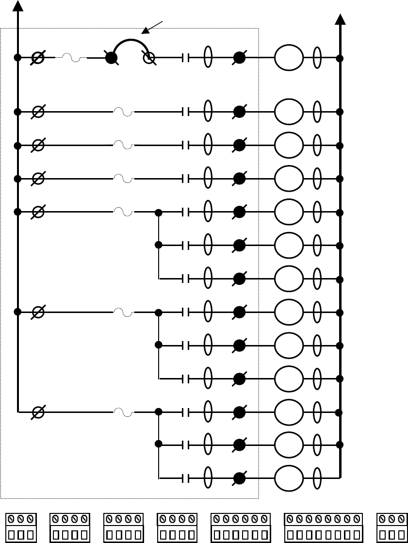
Section 6 - Wiring (Continued)
36
TABLE 1(H) TR12 WIRING DIAGRAM.
STANDARD 2-SPEED 4 MOTOR SYSTEM
MASTER
RELAY
MAIN LINE
CONTACTOR
MOTOR 4 (M4)
(M4) DIR 1
(M4) 2ND SPD
(M4) DIR 2
MOTOR 1 (M1)
(M1) DIR 1
(M1) 2ND SPD
(M1) DIR 2
MOTOR 2 (M2)
(M2) DIR 1
(M2) 2ND SPD
(M2) DIR 2
MOTOR 3 (M3)
(M3) DIR 1
(M3) 2ND SPD
DIR 1
(M3) DIR 2
Receiver Panel
J6-2
J5-5
J5-3
J5-1
J4-4
J3-4
J2-4
J6-3
J5-6
J5-4
J5-2
J4-3
J4-2
J4-1
J3-3
J3-2
J3-1
J2-3
J2-2
J2-1
HOT RETURN
K13
K12
K11
K10
K9
K8
K7
K6
K5
K4
K3
K2
K1
MLC
C12
C11
C10
C9
C8
C7
C6
C5
C4
C3
C2
C1
F7
F6
F5
F4
F3
F2
J7-3
J7-2
J7-1
J6-8
J6-7
J6-6
J6-5
J6-4
J6-3
J6-2
J6-1
J5-6
J5-5
J5-4
J5-3
J5-2
J5-1
J4-4
J4-3
J4-2
J4-1
J3-4
J3-3
J3-2
J3-1
J2-4
J2-3
J2-2
J2-1
J1-3
J1-2
J1-1
External jumper
in J6 connector
J6-4 J6-5
F8
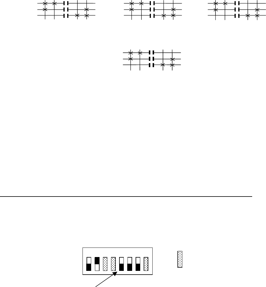
Section 6 - Wiring (Continued)
37
TABLE 2(H) TR12 2-SPEED PROGRAMMING DIAGRAM.
STANDARD 2-SPEED 4 MOTOR SYSTEM
MOTOR 1 CONNECTIONS MOTOR 2 CONNECTIONS MOTOR 3 CONNECTIONS
J4-3 MAIN HOIST UP J3-3 TROLLEY DIR 1 J2-3 BRIDGE DIR 1
J4-2 MAIN HOIST 2ND SPEED J3-2 TROLLEY 2ND SPEED J2-2 BRIDGE 2ND SPEED
J4-1 MAIN HOIST DOWN J3-1 TROLLEY DIR 2 J2-1 BRIDGE DIR 2
J4-4 HOT (J4-1, 2 & 3) J3-4 HOT (J3-1, 2 & 3) J2-4 HOT (J2-1, 2 & 3)
MOTOR 4 CONNECTIONS
J5-6 AUX HOIST UP J5-5 HOT AUX HOIST UP
J5-4 AUX HOIST 2ND SPEED J5-3 HOT AUX HOIST 2ND SPEED
J5-2 AUX HOIST DOWN J5-1 HOT AUX HOIST DOWN
NOTE
CHECK GOVERNMENTAL AND LOCAL REGULATIONS ON THE REQUIREMENTS OF HORNS OR ALARMS
BEFORE USING THIS CONFIGURATION, AS THERE IS NOT A SEPARATE ALARM CONTROL.
TRANSMITTER SWITCH SETTINGS (This configuration does not apply to the Membrane transmitter).
telePilot USE PDA SCREEN (Program the configuration switches 5, 6 and 7 to OFF. Under MAIN/AUX select the
motor desired to be the AUX ; MOT 1, MOT 2 or MOT 3. For a Main and Aux Hoist select MOT 1).
PENDANT, JLTX AND SLTX TRANSMITTER SWITCH SW4 “D” SETTINGS:
Position-1 Position-2 Position-5 Position -6 Position –7
OFF ON OFF OFF OFF
*NOTE: Hoist, Trolley and Bridge are listed here as traditional configurations, the installer may choose to define the
motors differently.
OUTPUTS
J2-3
J2-2
J2-1
BRIDGE*
MOTOR 3
1ST 2ND
Dir 1 Dir 2
OUTPUTS
J4-3
J4-2
J4-1
MAIN HOIST*
MOTOR 1
1ST 2ND
UP DN
2ND 1ST 2ND 1ST
OUTPUTS
J3-3
J3-2
J3-1
TROLLEY*
MOTOR 2
1ST 2ND
Dir 1 Dir 2
2ND 1ST
OUTPUTS
J5-6
J5-4
J5-2
AUX HOIST*
MOTOR 4 1ST 2ND
UP DN
2ND 1ST
OFF
1 2 3 4 5 6 7 8 ON
For these switch
positions see
previous section.
Indicates Switch in OFF Position.
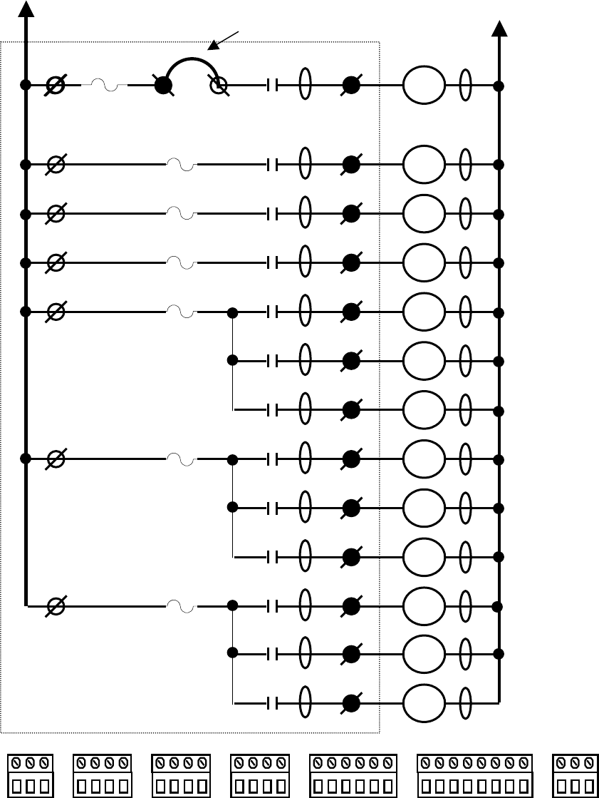
Section 6 - Wiring (Continued)
38
TABLE 1(I) TR12 WIRING DIAGRAM.
STANDARD 2-SPEED 3, 4 & 5 MOTOR SYSTEM using SELECT
MASTER
RELAY
MAIN LINE
CONTACTOR
AUX 3
ALARM
SELECT 1
SELECT 2
MOTOR 1 (M1)
(M1) DIR 1
(M1) 2ND SPD
(M1) DIR 2
MOTOR 2 (M2)
(M2) DIR 1
(M2) 2ND SPD
(M2) DIR 2
MOTOR 3 (M3)
(M3) DIR 1
(M3) 2ND SPD
DIR 1
(M3) DIR 2
Receiver Panel
J6-2
J5-5
J5-3
J5-1
J4-4
J3-4
J2-4
J6-3
J5-6
J5-4
J5-2
J4-3
J4-2
J4-1
J3-3
J3-2
J3-1
J2-3
J2-2
J2-1
HOT RETURN
K13
K12
K11
K10
K9
K8
K7
K6
K5
K4
K3
K2
K1
MLC
C12
C11
C10
C9
C8
C7
C6
C5
C4
C3
C2
C1
F7
F6
F5
F4
F3
F2
J7-3
J7-2
J7-1
J6-8
J6-7
J6-6
J6-5
J6-4
J6-3
J6-2
J6-1
J5-6
J5-5
J5-4
J5-3
J5-2
J5-1
J4-4
J4-3
J4-2
J4-1
J3-4
J3-3
J3-2
J3-1
J2-4
J2-3
J2-2
J2-1
J1-3
J1-2
J1-1
External jumper
in J6 connector
J6-4 J6-5
F8
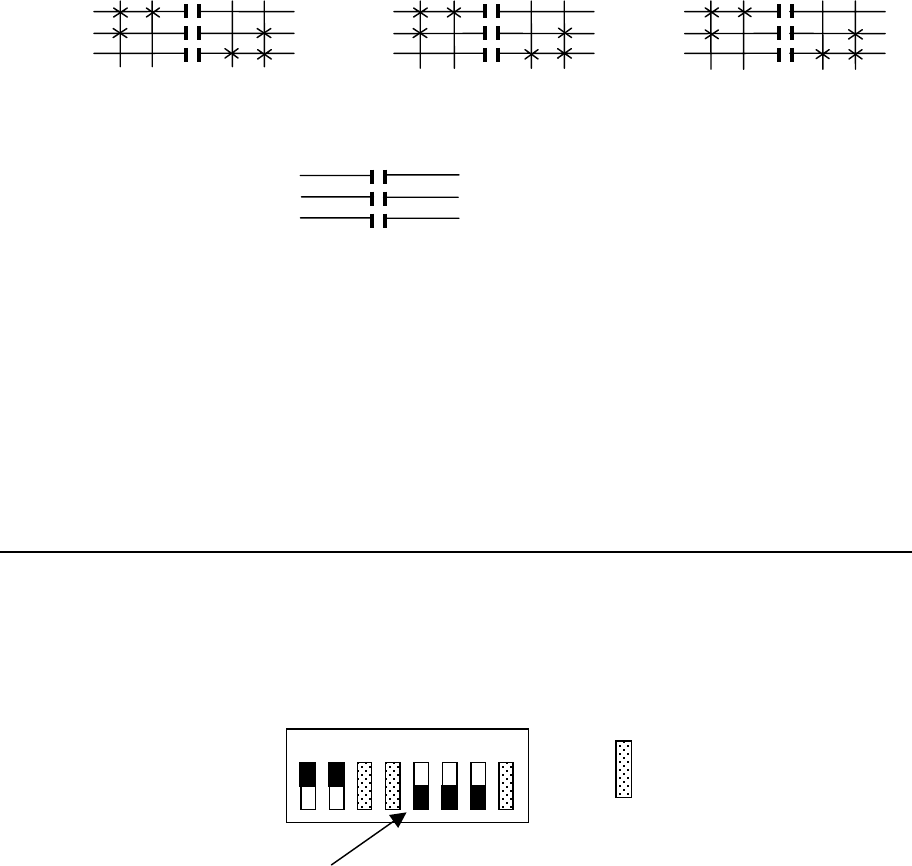
Section 6 - Wiring (Continued)
39
TABLE 2(I) TR12 2-SPEED PROGRAMMING DIAGRAM.
STANDARD 2-SPEED 3, 4 & 5 MOTOR SYSTEM using SELECT
MOTOR 1 CONNECTIONS MOTOR 2 CONNECTIONS MOTOR 3 CONNECTIONS
J4-3 MAIN HOIST UP J3-3 TROLLEY DIR 1 J2-3 BRIDGE DIR 1
J4-2 MAIN HOIST 2ND SPEED J3-2 TROLLEY 2ND SPEED J2-2 BRIDGE 2ND SPEED
J4-1 MAIN HOIST DOWN J3-1 TROLLEY DIR 2 J2-1 BRIDGE DIR 2
J4-4 HOT (J4-1, 2 & 3) J3-4 HOT (J3-1, 2 & 3) J2-4 HOT (J2-1, 2 & 3)
INDEPENDENT CONNECTIONS
J5-2 SELECT 2 J5-1 HOT SELECT 2
J5-4 SELECT 1 J5-3 HOT SELECT 1
J5-6 AUX 3 ALARM J5-5 HOT AUX 3 ALARM
TRANSMITTER SWITCH SETTINGS (This configuration does not apply to the Membrane transmitter).
telePilot USE PDA SCREEN (Program the configuration switches 5, 6 and 7 to OFF. Under MAIN/AUX select the
word “SELECT”).
PENDANT, JLTX AND SLTX TRANSMITTER SWITCH SW4 “D” SETTINGS:
Position-1 Position-2 Position-5 Position -6 Position –7
ON ON OFF OFF OFF
*NOTE: Hoist, Trolley and Bridge are listed here as traditional configurations, the installer may choose to define the
motors differently.
Additional programming available:
The select function can be inverted by turning switch position 4 to ON (the Configuration Switch on the telePilot or SW4
“D” for the Pendant, JLTX and SLTX).
Tandem select operation, both select 1 and 2 on at the same time, can be disabled by turning switch position 3 to ON (the
Configuration Switch on the telePilot or SW 4 “D” for the Pendant, JLTX and SLTX).
OFF
1 2 3 4 5 6 7 8 ON
For these switch
positions see
previous section.
Indicates Switch in OFF Position.
OUTPUTS
J2-3
J2-2
J2-1
BRIDGE*
MOTOR 3 1ST 2ND
Dir 1 Dir 2
OUTPUTS
J4-3
J4-2
J4-1
MAIN HOIST*
MOTOR 1 1ST 2ND
UP DN
2ND 1ST 2ND 1ST
OUTPUTS
J3-3
J3-2
J3-1
TROLLEY*
MOTOR 2
1ST 2ND
Dir 1 Dir 2
2ND 1ST
J5-2
J5-4
J5-6
SELECT 2
SELECT 1
AUX 3 ALARM
INDEPENDENT OUTPUTS
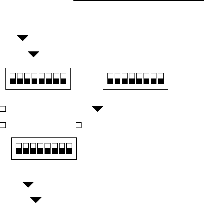
Section 7 – Programming
40
7-1. Programming Access Codes.
The access code is set at the factory and should not be
changed unless absolutely necessary. If you are
reprogramming a spare or “Minuteman” transmitter
make sure the other transmitter is securely taken out of
service.
WARNING
TWO OPERATIONAL TRANSMITTERS WITH THE
SAME ACCESS CODES OPERATING AT THE
SAME TIME IS A DEFINITE SAFETY HAZARD.
TeleMotion receivers are shipped with the access code
settings for the transmitter marked on the receiver door
for both styles of transmitters.
Also a label on the transmitter lists the access code
settings inside. The positions on the transmitter label
match the switch settings. The “1” by A1 means the
switch position A1 should be ”ON” and “0” means A1
should be “OFF”.
7-2. Changing Transmitter Access Codes.
System “10K”
Frequency
A1 B1
0
1
0
1
Receiver Access Code
Multibox Tx #
Auto Turn Off Auto Alarm
1
Main/Aux “Aux”
S3- 1 1
0
Switch Conf. H, T, B
Timer

Section 7 - Programming (Continued)
41
WARNING
AFTER CHANGING THE ACCESS CODES ON THE
TRANSMITTER, TEST THE UNIT BY TURNING IT
ON AND OFF NEAR THE APPROPRIATE
RECEIVER. IF THE RECEIVER DOES NOT
RESPOND, DO NOT ACTIVATE A FUNCTION
BUTTON! THE TRANSMITTER MAY HAVE THE
WRONG ACCESS CODE, WHICH COULD MOVE
ANOTHER CRANE. RE-CHECK THE ACCESS
CODE IN THE TRANSMITTER AND RETEST.
7-2.1. Transmitter.
Open the back battery door and take out the batteries as a
safety precaution.
Remove the 6 screws on the front cover. Lift out switch-
pad, logic board and turn logic board over.
Locate the dipswitches marked “A” and “B”. With a pen
or pointed object toggle the switches to match the
Membrane Transmitter Code Diagram on the door of the
receiver. A dot on the switch diagram means that switch
position is ON.
CAUTION
DO NOT USE A PENCIL TO TOGGLE THE
SWITCHES. THE LOOSE GRAPHITE FROM THE
PENCIL CAN DAMAGE THE SWITCH.
Reassemble unit; replace the batteries and test.
7-3. Transmitter.
Open the back battery door and take out the batteries as a
safety precaution.
Remove the 8 screws on the front cover. Turn transmitter
over and remove back cover.
Locate the dipswitches marked “A” and “B”. With a pen
or pointed object toggle the switches to match the
Pendant Transmitter Code Diagram on the door of the
receiver. A dot on the switch diagram means that switch
position is ON.
Reassemble unit; replace the batteries and test.Receiver
Unit Access Code Setting.
The access code is preset at the factory and should not be
changed unless absolutely necessary. There are two
separate microprocessors in the TeleMotion unit. Each
microprocessor has its own pair of access code switches
for additional reliability. The two pairs of access code
switches are labeled “A1, B1” and “A2, B2”. A1 must
match the settings of A2 and B1 must match the settings
of B2 or the unit will not work. See Figure 7-2. Access
Code Setting.
The programming in the receiver must match the
transmitter. If looking at the label on the outside of the
transmitter, take note that positions “A” and “B” number
from the left 1 through 8. In the receiver 8 is closer to the
bottom of the unit and 1 is closer to the top.
NOTE
IN EVENT PROGRAMMING OF ACCESS CODES IS
REQUIRED, TAKE SPECIAL CARE TO
CORRECTLY LOCATE ACCESS CODE SWITCHES
A AND B. LOOK FOR THE LABELS A AND B ON
THE PRINTED CIRCUIT BOARD NEAR THE
RESPECTIVE SWITCHES. DETERMINE THEIR
ORIENTATION. THE SWITCHES MAY NUMBER
FROM LEFT TO RIGHT OR RIGHT TO LEFT. LOOK
FOR THE NUMBERING ON THE SWITCHES.
MATCH ACCESS CODES A1, A2, - -- B1, B2 ETC.
After changing the access code test the receiver with a
matching transmitter. (If only one of the two red LEDs
DS12 and DS20 come on, then check the access code
settings on the receiver. (Check A1-B1 if DS20 is lit or
A2-B2 if DS12 is lit). If both LEDs are lit, both sets of
access codes do not match the transmitter.
7-5. Transmitter Programming (Other).
This applies to Membrane and Pendant transmitter
dipswitches SW3 and SW4. These are transmitter-
programming switches (not the access code switches) in
both types of transmitters these should always all be in
the “OFF” position for use with a TeleMotion unit.
These switches are used for other Telemotive receivers.
If replacing a Membrane transmitter with a Pendant
transmitter on an existing installation or making them
interchangeable and keeping the existing receiver wiring,
open the Pendant transmitter, find dip switch SW3 and
move position 1 (SW3) to “ON”. The Pendant
transmitters labeling and functions North and South, East
and West will match the Membrane transmitter.
If replacing a Pendant transmitter with a Membrane
transmitter on an existing installation or to making them
interchangeable and keeping the existing receiver wiring,
open the Membrane transmitter, find dip switch SW3
and move position 1 (SW3) to “ON”. The Membrane
transmitters labeling and functions North and South, East
and West will match the Pendant transmitter.
Section 7 - Programming (Continued)
42
Section 7 - Programming (Continued)
43
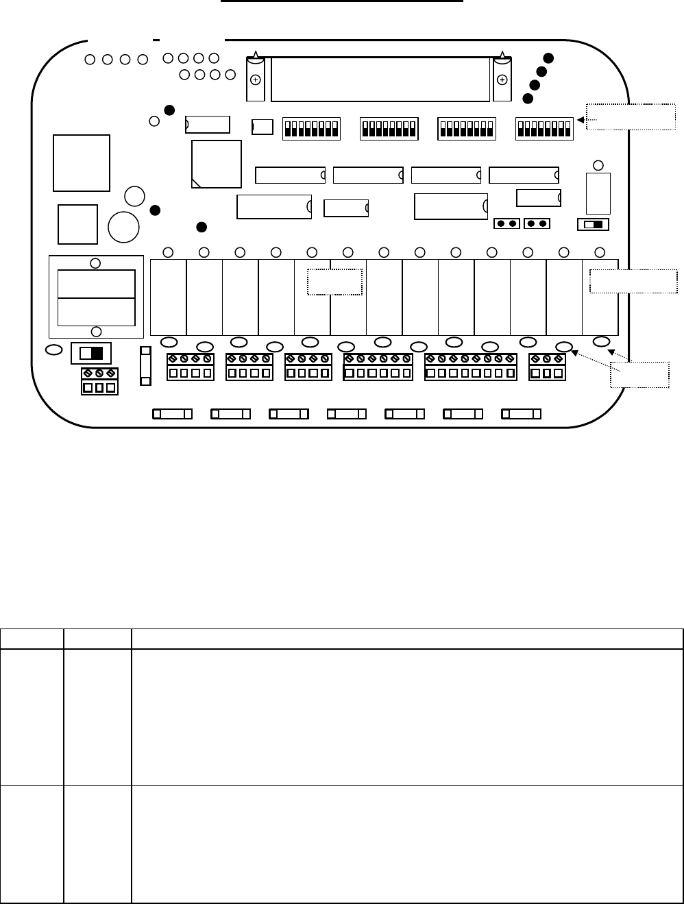
Section 8 – Servicing
44
NOTE
IF THE SYSTEM STOPS WORKING CHECK THE RED INDICATOR ON THE TRANSMITTER. IF IT
DOES NOT COME ON WITH PUSHING THE ON BUTTON OR THE RED WEAK BATTERY LIGHT
IS ON (FOR THE telePilot TRANSMITTER) REPLACE THE TRANSMITTER BATTERIES.
Table 8-1. Receiver Diagnostic LED Functions. (See Figure 8-1. Receiver Layout for LED locations).
LED COLOR FUNCTION
DSMR1 Yellow Monitors closure of the Security Relay output (KMR1).
The LED will be illuminated when the Security Relay has been enabled by an ON command
received from the Transmitter Unit. LED will extinguish when an OFF command is transmitted,
or an EMS condition is present.
The Security Relay controls the 12 VDC power to the MCR relay (K13) and the power to the coils
of the control relays (K1 through K12) on the Relay Output Modules.
DSMR2 Red Monitors closure of the Master Control Relay (MCR) relay (K13).
LED will be illuminated when the MCR relay has been enabled by an ON command recieved
from the Transmitter Unit. Led will extinguish, when an OFF command has been transmitted, an
EMS condition is present, or SW2 is set to OFF.
The MCR controls the 12 VDC power to the Master Relay on the Power Supply Board.
GND N 120V
F1
8 7 6 5 4 3 2 1 8 7 6 5 4 3 2 1 8 7 6 5 4 3 2 1 8 7 6 5 4 3 2 1
SW4 ON
SW3 ON
A SW2 ON
B SW1 ON
DS1 DS2 DS3 DS4 DS5 DS6 DS7 DS8 DS9 DS10 DS11 DS12 DSMR2
TP4
TP5 AGC
TP7 DATA
TP6 ANALOG
TP2 GND
DS13
DS23
DS22
DS24
DS21
DS20
DS18
DS16
TP3
+12V
TP1
+5V
DS15
+5V
RF Receiver Assembly
MOV’s
Dip Switches
KMR1
EPROM
WAC1
EMS1
+12V
5V DC
K1 K2 K3 K4 K5 K6 K7 K8 K9 K10 K11 K12 K13
DSMR1
SW2 ON
ON SW1
DS19
DS17
DS15
DS14
F2 F3 F4 F5 F6 F7 F8
J2 J3 J4 J5 J6 J7
JU2 JU1
Relays Master Relay
1 1 1 1 1 1
1
Figure 8-1. Receiver Layout

Section 8 – Servicing (Continued)
45
DS1-DS12 Red Monitors closure of the output relays (K1-K12).
Normally ON for a function when that specific function is enabled.
The LED will be illuminated when a specific relay has been enabled by the respective command
received from the Transmitter Unit. The LED will extinguish, when the command is no longer
detected.
DS13 Red Monitors the watchdog timer.
Normally OFF.
The LED will illuminate momentarily when power is applied to or removed from the system. If
the LED is continuously flashing or on, the computer is not working properly. If LED is
illuminated constantly (no flashing), the +5 VDC is probably too low. This could be caused by
shorts on the board or by a defective voltage regulator. If the LED flashes at a constant rate, the
microcomputer chip or EPROM may be defective.
DS14 Yellow Monitors data synchronization. (Flashes when a properly formatted data signal is received from
the transmitter).
This LED will flash rapidly when data is transmitted. The LED can be used with DS16 to analyze
incoming data. If DS16 is illuminated or flashing when DS14 also is flashing, another
Transmitter Unit on the same frequency may be present. This is normal. As more Transmitter
Units operated on the same frequency, LED will flash brighter and more often.
DS15 Yellow Monitors continuity between receiver RF module and CPU module.
Normally ON.
Off indicates a malfunctioning receiver.
DS16 Red Monitors received data errors.
Normally OFF.
A flashing LED during data transmission may indicate interference of the received data. If LED
is illuminated continuously when data is transmitted and the system will not respond the Access
Code of the Receiver and Transmitter Units may not match. If LED is illuminated when data is
not transmitted, another Transmitter Unit may be present on the same frequency with a different
Access Code. The presence of activity on this LED does not necessarily indicate a problem. It
should be used with other indicators in analyzing system status.
DS17 Yellow Monitors system acitivty.
Normally FLASHING.
If not flashing the microprocessor is dead.
DS18 Red Monitors the ON command from the Transmitter.
LED will flash when an ON command is being received from the Transmitter.
While pushing the ON button on the Transmitter this should light.
DS19 Red Monitors EMS condition.
Normally OFF.
LED will flash when an EMS command is transmitted and illuminate continuousl
y
when the EMS

Section 8 – Servicing (Continued)
46
condition is in effect. An EMS condition may be created when an EMS command is transmitted
or when a failure mode is detected by the slave microcomputer. If both DS18 and DS19 are
illuminated, a contact monitoring error has been detected. If both DS16 and DS19 are
illuminated, the incoming data on the ICC bus has been corrupted.
DS20 Red Monitors the OFF command from the Transmitter.
LED will flash when an OFF command is being received from the Transmitter Unit.
While pushing the OFF button on the Transmitter this should light.
DS21 Yellow Monitors the activity for the Security Relay (KMR1).
Normally ON when the receiver is enabled.
If the system is ON and the light is not lit there is a serious microprocessor error.
DS22
Green
Monitors the unregulated DC power to the 12 volt regulator
Normally ON when AC line is present.
If AC Power is present and the AC to DC converter is working then the LED is illuminated. The
LED is off if DC power is not present. Check power supply, fuses and if power is applied to the
receiver.
DS23 Green
Monitors the regulated 12 VDC power to the Board (receiver board).
Normally ON when AC line is present.
If 12 VDC power is present then the LED is illuminated. The LED is off if 12 VDC power is not
present. Check the 12 VDC regulator and for shorts on the Board.
DS24 Green
Monitors regulated 5 VDC power to the Board.
Normally ON when AC line is present.
If 5 VDC power is present then the LED is illuminated. The LED is off if 5 VDC power is not
present. Check the 5 VDC regulator and for shorts on the Board.
8-1. Receiver Test Points.
Test points are shown as stars on Figure 8-1. Receiver Layout.
TP1 – Monitors regulated 5 VDC
TP2 – Ground for monitoring other test points.
TP3 – Monitors regulated 12VDC.
TP4 – Not used.
TP5 – Monitors AGC (Automatic Gain Control) from RF Receiver module.
TP6 – Monitors analog signal from RF Receiver module.
TP7 – Monitors received data from RF Receiver module.
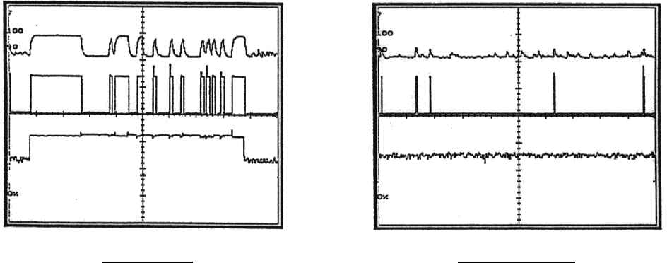
Section 8 – Servicing (Continued)
47
8-2. Typical Wave Forms on an Oscilloscope.
Receiving Data Not Receiving Data
Scope Settings:
Sweep – 1 millisecond per division.
Sensitivity – TP6 1 volt per division 10X probe.
TP7 2 volts per division 10X probe.
TP5 1 volt per division 10X probe.
TP6
ANALOG
TP7
DATA
TP5
AGC
Figure 8-2. Receiver Scope Wave Forms.

Section 9 – Spare Parts
48
PART NUMBER DESCRIPTION
RECEIVER
FW2911-0 EPROM
E13151-3.2-01 RF RECEIVER MODULE ASSEMBLY
H310-0 RF RECEIVER MODULE ASSEMBLY MOUNTING SCREWS (4)
MP18005-0 RF RECEIVER MODULE MOUNTING BRACKET TOP SIDE (LEFT)
MP18005-1 RF RECEIVER MODULE MOUNTING BRACKET TOP SIDE (RIGHT)
H906-0 RF RECEIVER MODULE MOUNTING BRACKET BOLT (2)
H934-0 RF RECEIVER MODULE MOUNTING BRACKET NUT (2)
E10100-1 MAIN BOARD
H1224-1 MAIN BOARD MOUNTING SCREWS (5)
E10197-0 ANTENNA ASSEMBLY (INTERNAL)
CONNECTOR PLUG IN:
TS1060-3 3 POSITION (2)
J4655-0 6 POSITION
TS1060-8 8 POSITION
CR260-0 MOV
K1304-0 RELAY (OUTPUT) (7)
S2721-8 DIP SWITCH (ACCESS CODE) (4)
MP10267-0 HOUSING ASSEMBLY, CASE DOORS, SCREWS
E10196-0 FILTER ASSEMBLY
H1223-0 SCREW ROUND HEAD #10-24 X 1”
H1226-0 HEX NUT #10-24
H2079-0 LOCK WASHER #10 SPLIT
TC10K-TR6 INSTRUCTION MANUAL
F2711-2 FUSE ½ AMP, SLO BLO 250V
F2711-0 FUSE 10 AMP SLO BLO 250V
MEMBRANE TRANSMITTER
F2712-1.5 FUSE 1.5 AMP, 250V FAST ACTING 2 AG
FW2836-0 TWO SPEED TACTILE MEMBRANE EPROM FOR TRANSMITTER M/C
MODULE E10635
A9654-0 STRAP ASSEMBLY
A10662-1 TRANSMITTER CASE ASSEMBLY
E9654-0 BATTERY HOLDER ASSEMBLY
A10664-2 BATTERY DOOR ASSEMBLY
E10640-2 BEZEL ASSEMBLY (TWO-SPEED TRANSMITTER)
S22803-0 MEMBRANE SWITCH PAD (TACTILE)
MP9656-0 VINYL POUCH
A9665-0 RUBBER BOOT ASSEMBLY
AA CELL 1.5 VOLTS BATTERY (5)
PENDANT TRANSMITTER
E10668-11 CASE, TOP PENDANT TRANSMITTER, COMPLETE WITH SWITCHES,
DECALS, BOOTS
MP10668-1 CASE ONLY, TOP PENDANT TRANSMITTER
H634-0 BOOT, GRAY (PUSHBUTTON)
H635-0 BOOT, RED (PUSHBUTTON)
H2055-3 LENS/MOUNT, LED W/SPACER, RED
S1058-0 SWITCH, PUSHBUTTON, TWO-SPEED SBRU-SD
S1026-0 SWITCH, PUSHBUTTON, MOM N/0
S1041-0 SWITCH, TOGGLE, SPDT, CTR OFF
MP10666-0 KNOB, ROTARY 1/2" DIA., BLACK

Section 9 – Spare Parts (Continued)
49
MP10661-0 BOOT, TOGGLE SW., BLACK
A10667-5 BOTTOM CASE W/O BATTERY DOOR
A10669-1 BATTERY DOOR W/FOAM, W/O SCREWS AND LATCH
MP10676-0 FOAM, BATTERY DOOR
PART NUMBER DESCRIPTION
PENDANT TRANSMITTER (CONTINUED)
MP10677-0 GASKET FOR BOTTOM CASE
H1047-0 COVER SCREWS (8)
MP1049-0 SWITCH GUARD WITH SCREWS
E10668-11LT SAME AS E1066-11 BUT WITH SWITCH GUARD AND LARGE TOGGLES
MP10668-3 CASE TOP ONLY, LARGE TOGGLES
S605-0 SWITCH, TOGGLE SPDT CENTER OFF, LARGE
A1011–X BOOTS (6) (SEE *NOTE 1 BELOW FOR THE PROPER SUFFIX)
MP10650-1 LATCH FOR BATTERY DOOR
S605-0 SWITCH, TOGGLE SPDT CENTER OFF, LARGE
A1011–X BOOTS (6) (SEE *NOTE 1 BELOW FOR THE PROPER SUFFIX)
H251-0 SCREW FOR BATTERY DOOR LATCH
H252-0 WAVE WASHER FOR BATTERY DOOR LATCH
H2034-0 FLAT WASHER FOR BATTERY DOOR LATCH
N13653-2 FCC LABEL
E10688-0 BATTERY HOLDER ASSEMBLY, W/CABLE
MP10680-0 O'RING
MP10678-0 SHOULDER STRAP
BT10KP-0 BATTERY, ALKALINE
BT10KP-1 BATTERY, NICAD
E10670-1 BATTERY CHARGER
A10669-1 BATTERY DOOR
*NOTE 1 UP DOWN EAST WEST NORTH SOUTH
YELLOW 23 24 31 32 29 30
BLACK 3 4 11 12 9 10