Telensa 2NXN Telecell with location User Manual Installation Guide
Telensa Ltd. Telecell with location Installation Guide
Telensa >
User Manual Installation Guide

COMMERCIAL IN CONFIDENCE
6LT041 05 29 Oct 2014 Page 1 of 9
QP4016 06 - Tech Note Template
Technical Note
Subject:
User Manual and instructions for the EU & US Telecell
Date:
29 Oct 2014
Document ref:
6LT041 05
Intentionally Blank
6LT041 05 29 Oct 2014
QP4016 07- Tech Note Template
Telensa
Telecell 2 User Manual
6LT041 05 29 Oct 2014
QP4016 07- Tech Note Template
Contents
CONTENTS ................................................................................................................................................................ 3
1 OPERATIONAL SAFETY NOTICES ............................................................................................................ 4
2 TELECELL VARIANTS .................................................................................................................................. 4
3 SPECIFICATIONS ........................................................................................................................................... 4
3.1 EU TYPE PRODUCTS, T2E… ....................................................................................................................... 4
3.2 US TYPE PRODUCTS, T2A… ....................................................................................................................... 4
3.3 NOTES ON DIMMING CONTROL OUTPUTS ...................................................................................................... 5
4 INSTALLATION INSTRUCTIONS ............................................................................................................... 5
4.1 DIMMING CONTROL TELECELL .................................................................................................................... 5
4.2 STANDARD (NON DIMMING) TELECELL ........................................................................................................ 5
5 TELECELL CONNECTION DIAGRAMS .................................................................................................... 6
6 NOTICES FOR PRODUCTS OPERATED IN THE USA & CANADA ...................................................... 9
6LT041 05 29 Oct 2014
QP4016 07- Tech Note Template
1 Operational Safety Notices
Installer
Installers must be suitably trained and qualified for electrical work, according to the laws and local codes
for the locality and country where the unit will be installed.
This unit must only be installed by personnel that have been trained by Telensa or their representatives to
carry out this work.
Power Supply
In the case of field installation the supply voltage present on the luminaire NEMA socket is hazardous
and all necessary precautions must be taken to ensure the safety of the installer. Isolate the supply to the
NEMA socket before removing an old photocontrol, or installing the telecell.
2 Telecell Variants
There are two variants of the Telecell 2 model; dimming control and standard / non-dimming control.
Dimming control products are identified by the text “0-10V & DALI” on the product label.
Telecell products are built and supplied to either the EU or US standards:
EU product part numbers start with: T2E... US part numbers start with T2A…
The products are supplied with NEMA pin connections for insertion into the photocell socket on top of a
luminaire.
3 Specifications
3.1 EU Type Products, T2E…
Electrical Parameters: Supply voltage: 100 - 253 VAC, 50-60Hz
Maximum switching current: 10A
Radio: Transmit Power: 25mW EIRP, <1% transmit duty cycle.
Operating band: 868MHz license free ISM band
Operating Temperature: NEMA variants: -40 to 70 °C Ambient
3.2 US Type Products, T2A…
Electrical Parameters: Supply voltage: 100 - 277 VAC, 50-60Hz
Maximum switching current: 10A
Radio: Transmit Power: 100mW EIRP
Operating band: 915MHz license free ISM band
Operating Temperature: NEMA variants: -40 to 70 °C Ambient
6LT041 05 29 Oct 2014
QP4016 07- Tech Note Template
3.3 Notes on dimming control outputs
These notes apply to products with the integrated dimming control function:
Suitable for use with dimmable ballasts with an isolated or non-isolated control input
DALI or 0-10V control mode is configured over the air by the Telensa Central System
0-10V control requires the normally fitted internal pull-up resistor in the ballast
DALI control includes the DALI supply function within the telecell and is suitable for
controlling from one to three dimmable ballasts.
4 Installation Instructions
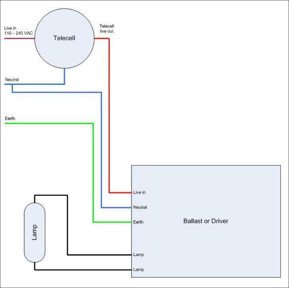
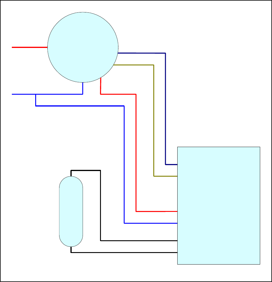
Instructions for the installation of each of the different variants of Telecell are given below. Figure 2
shows a wiring diagram for a standard lamp with a non-dimmable ballast. Figure 3 shows dimming
control using a dimmable ballast.
4.1 Dimming Control Telecell
This product will ONLY control a lamp that incorporates a 5 or 7 pin NEMA socket compliant
with ANSI C136.41 2013.
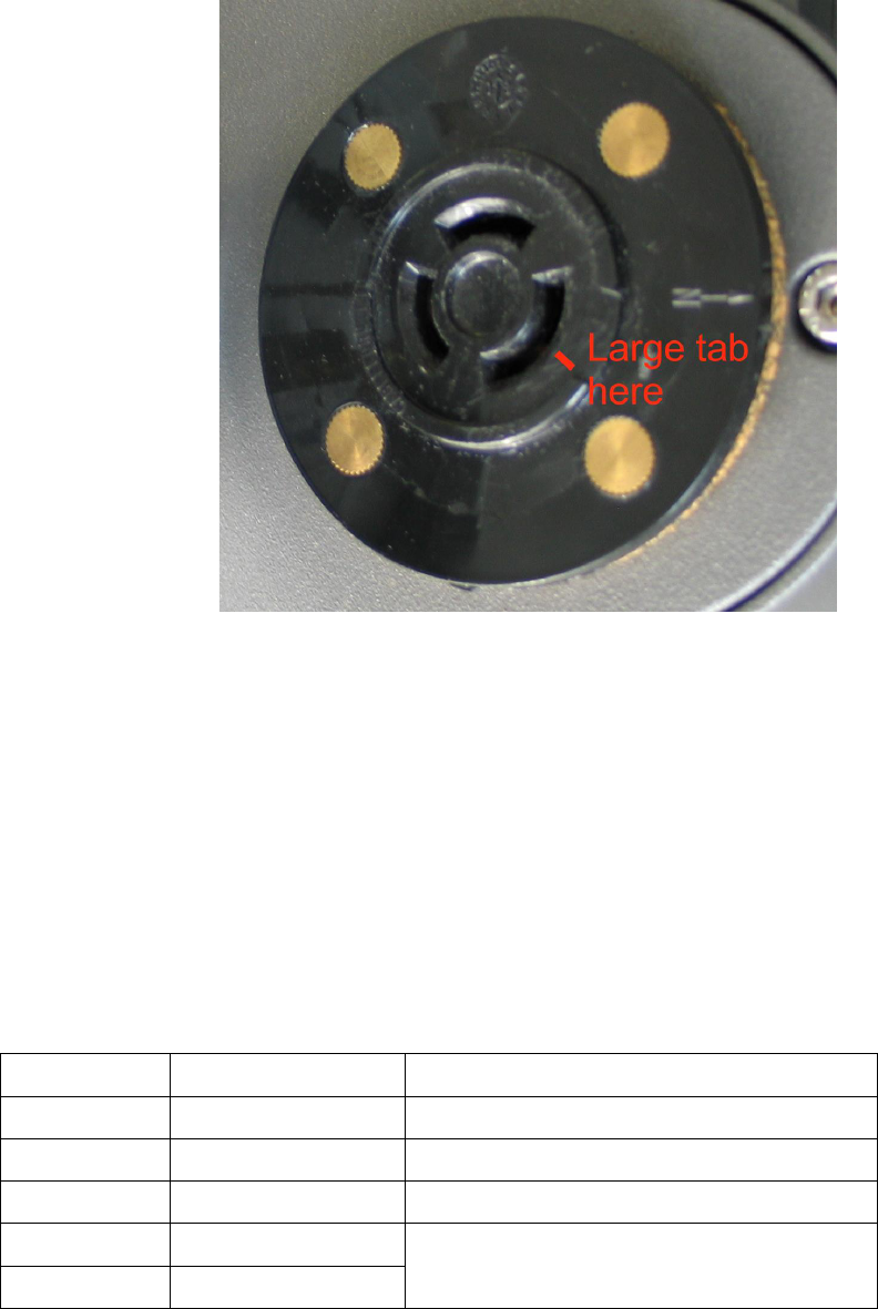
Insert unit into NEMA socket on street light ensuring the largest tab on the unit places into the largest tab
recess on the NEMA socket on the street light. Turn by hand clockwise typically 30 degrees to lock in
place.
4.2 Standard (non dimming) Telecell
Insert unit into NEMA socket on street light ensuring the largest tab on the unit places into the largest tab
recess on the NEMA socket on the street light. Turn by hand clockwise typically 30 degrees to lock in
place.
6LT041 05 29 Oct 2014
QP4016 07- Tech Note Template
Fig 1: Example NEMA socket showing alignment
5 Telecell Connection Diagrams
Refer to figures 2 and 3 overleaf.
Colour code
Function
Notes
Brown
LIVE/LINE in
Blue
NEUTRAL in
Red
LIVE switched out
Relay switched inside telecell
Violet
+ Dimmer control
Integrated dimming function telecells only.
DALI control is not polarity sensitive.
Grey
- Dimmer control
6LT041 05 29 Oct 2014
QP4016 07- Tech Note Template
Figure 2: Wiring Diagram for Telecell - No Dimming Function
6LT041 05 29 Oct 2014
QP4016 07- Tech Note Template
Telecell
Dimmable
Ballast
Lamp
Live in
Neutral Live out
Dimmer control
Lamp
Lamp
Neutral
Live in
Ctrl 1
Ctrl 2
Figure 3: Wiring Diagram for Integral Dimming Control Telecell
6LT041 05 29 Oct 2014
QP4016 07- Tech Note Template
6 Notices for products operated in the USA & Canada
This device complies with Part 15 of the FCC Rules. Operation is subject to the following two
conditions:
(1) this device may not cause harmful interference, and
(2) this device must accept any interference received, including interference that may cause undesired
operation.
This equipment has been tested and found to comply with the limits for a class B digital device, pursuant
to Part 15 of FCC rules. These limits are designed to provide reasonable protection against harmful
interference in a residential environment. This equipment generates, uses and can radiate radio frequency
energy and, if not installed and used in accordance with the instructions, may cause harmful interference
to radio communications. However, there is no guarantee that interference will not occur in a particular
installation If this equipment does cause harmful interference to radio or television reception, which can
be determined by turning the equipment off and on, the user is encouraged to try to correct the
interference by one of the following measures:
Reorient or relocate the receiving antenna
Increase the separation between the equipment and receiver
Consult a dealer or an experienced radio/TV technician for help.
Note that no changes shall be made to the equipment without the manufacturer’s permission as this may
void the user’s authority to operate the equipment.
This transmitter must not be co-located or operated with any other antenna or transmitter
This device complies with Part 2.1091 of the FCC Rules for an uncontrolled environment. This
equipment should be installed and operated with a minimum distance of 20cm between the radiator and
your body.
This device complies with RSS-310 of Industry Canada. Operation is subject to the condition that this
device does not cause harmful interference.