Telensa 2TXD Telecell with dimming control and external antenna User Manual Tech Note

Telensa Ltd. Telecell with dimming control and external antenna Tech Note

Contents

User Manual and Instructions

User Manual and Instructions for the US Telecell 2 Operational Safety Notices TL-004391-TN Issue 3 © Telensa Ltd 2017 Page 1                                         User Manual and Instructions for the US Telecell 2 Technical Note  CDox Original Author: Mike Martindell Other Authors: [free text field] CDox Latest Issuer: Mark Bailey Issue Date: 2017-11-16       Document Ref: TL-004391-TN  Issue 3
User Manual and Instructions for the US Telecell 2 Operational Safety Notices TL-004391-TN Issue 3 © Telensa Ltd 2017 Page 2
User Manual and Instructions for the US Telecell 2 Operational Safety Notices TL-004391-TN Issue 3 © Telensa Ltd 2017 Page 3  Notices  This document is provided to you by or on behalf of Telensa Ltd.  © Telensa Ltd 2017. The documentation and any software described herein and/or provided to you in conjunction with this documentation contain proprietary and confidential information of Telensa Ltd and may only be used subject to a license agreement containing restrictions on use and disclosure. They are also protected by copyright, patent rights and other intellectual and industrial property laws. The information contained in this document and any software described herein is subject to change without notice. If you find any problems in the documentation and/or the software, please report them to us in writing. The document and/or the software are not warranted to be error-free. No right, title, license or interest in any physically or electronically distributed materials is transferred to you by such distribution. No part of this document and/or the software may be reproduced, displayed, copied, translated, adapted, downloaded, electronically transmitted, used or reproduced in any form including (without limitation) distribution or storage in a system for retrieval without our express written permission (which may be subject to conditions). The documentation and/or software may provide links to Web sites and access to content, products, and services from third parties. Telensa Ltd is not responsible for the availability of, or any content provided on, third-party Web sites. You bear all risks associated with the use of such content. If you choose to purchase any products or services from a third party, the relationship is directly between you and the third party. Telensa Ltd is not responsible for: (a) the quality of third-party products or services; or (b) fulfilling any of the terms of the agreement with the third party, including delivery of products or services and warranty obligations related to purchased products or services. Telensa Ltd is not responsible for any loss or damage of any sort that you may incur from dealing with any third party. Telensa Ltd is the owner of the “Telensa” trademark and all associated trade names, logos and devices unless indicated to the contrary. Any other trademarks, logos and names appearing on in this document may be the property of their respective owners. Telensa Ltd is a Private Limited Company Registered in England and Wales Company No. 4498125  Registered Office: Telensa Ltd Iconix 3 London Road Pampisford CB22 3EG UK Tel: +44 (0) 1799 588 800  Further company information may be found at www.telensa.com.
User Manual and Instructions for the US Telecell 2 Operational Safety Notices TL-004391-TN Issue 3 © Telensa Ltd 2017 Page 4  Table of Contents 1 Operational Safety Notices ........................................................................... 5 1.1 Installer ........................................................................................................... 5 1.2 Power Supply .................................................................................................. 5 2 Product function............................................................................................ 6 3 Telecell Variants ............................................................................................ 7 4 Specifications ................................................................................................ 8 4.1 US Type Products, T2A… ............................................................................... 8 4.2 Notes on dimming control outputs ................................................................... 8 5 Installation Instructions ................................................................................ 9 5.1 Dimming Control NEMA Telecell T2A1N ......................................................... 9 5.2 Standard (non dimming) NEMA Telecell T2A1N .............................................. 9 5.3 Post Top Telecell Type T2A1P ........................................................................ 9 5.4 Two-part Telecell Type T2A1T ........................................................................ 9 5.5 External Antennas ......................................................................................... 10 6 Installation Logging .................................................................................... 11 7 Telecell Connection Diagrams ................................................................... 12 8 Notices for North America Region ............................................................. 14 8.1 United States of America ............................................................................... 14 8.2 Canada ......................................................................................................... 14
User Manual and Instructions for the US Telecell 2 Operational Safety Notices TL-004391-TN Issue 3 © Telensa Ltd 2017 Page 5  1  Operational Safety Notices 1.1  Installer Installers must be suitably trained and qualified for electrical work, according to the laws and local codes for the locality and country where the unit will be installed. This unit must only be installed by personnel that have been trained by Telensa or their representatives to carry out this work. 1.2  Power Supply In the case of field installation, the supply voltage present on the luminaire NEMA socket is hazardous and all necessary precautions must be taken to ensure the safety of the installer. Isolate the supply to the NEMA socket before removing an old photocontrol, and installing the Telecell.
User Manual and Instructions for the US Telecell 2 Product function TL-004391-TN Issue 3 © Telensa Ltd 2017 Page 6  2  Product function The Telecell is a radio controlled device and will only function as part of a Telensa Central Management System (CMS). Telecells are assigned to a specific CMS and cannot be transferred to another CMS without being re-assigned by Telensa. The Telecell operating program is set by the CMS and dusk/dawn lamp switching is remote controlled over the radio link by the associated CMS base stations. Typical maximum radio link distances are 2-3km in a urban areas and 3-10km in rural areas, depending on the terrain.
User Manual and Instructions for the US Telecell 2 Telecell Variants TL-004391-TN Issue 3 © Telensa Ltd 2017 Page 7  3  Telecell Variants There are two key variants of the Telecell 2 model; dimming control and standard / non-dimming control. Dimming control products are identified by the text “0-10V & DALI” on the product label. Telecell products are built and supplied to either the EU or US standards: US product part numbers start with T2A… The products are supplied with NEMA pin connections for insertion into the photocell socket on top of a luminaire. The Telecell variants included in this document are: Model Number Also Known As T2A1N NEMA Telecell T2A1P Post top Telecell T2A1U 2 part Telecell
User Manual and Instructions for the US Telecell 2 Specifications TL-004391-TN Issue 3 © Telensa Ltd 2017 Page 8  4  Specifications 4.1  US Type Products, T2A… Electrical Parameters: Supply voltage:      100 - 277 VAC, 50-60Hz   Maximum switching current:  10A             Radio: Transmit Power:      100mW EiRP Operating band:      902 to 928 MHz license free ISM band Operating Temperature:     NEMA variants:  -40 to 70 °C Ambient 4.2  Notes on Dimming Control Outputs These notes apply to products with the integrated dimming control function:   Suitable for use with dimmable ballasts with an isolated or non-isolated control input   DALI or 0-10V control mode is auto-selected by the Telecell by communicating with the connected ballast.    0-10V control requires the normally fitted internal pull-up resistor in the ballast   DALI control includes the DALI supply function within the Telecell and is suitable for controlling from one to three dimmable ballasts.
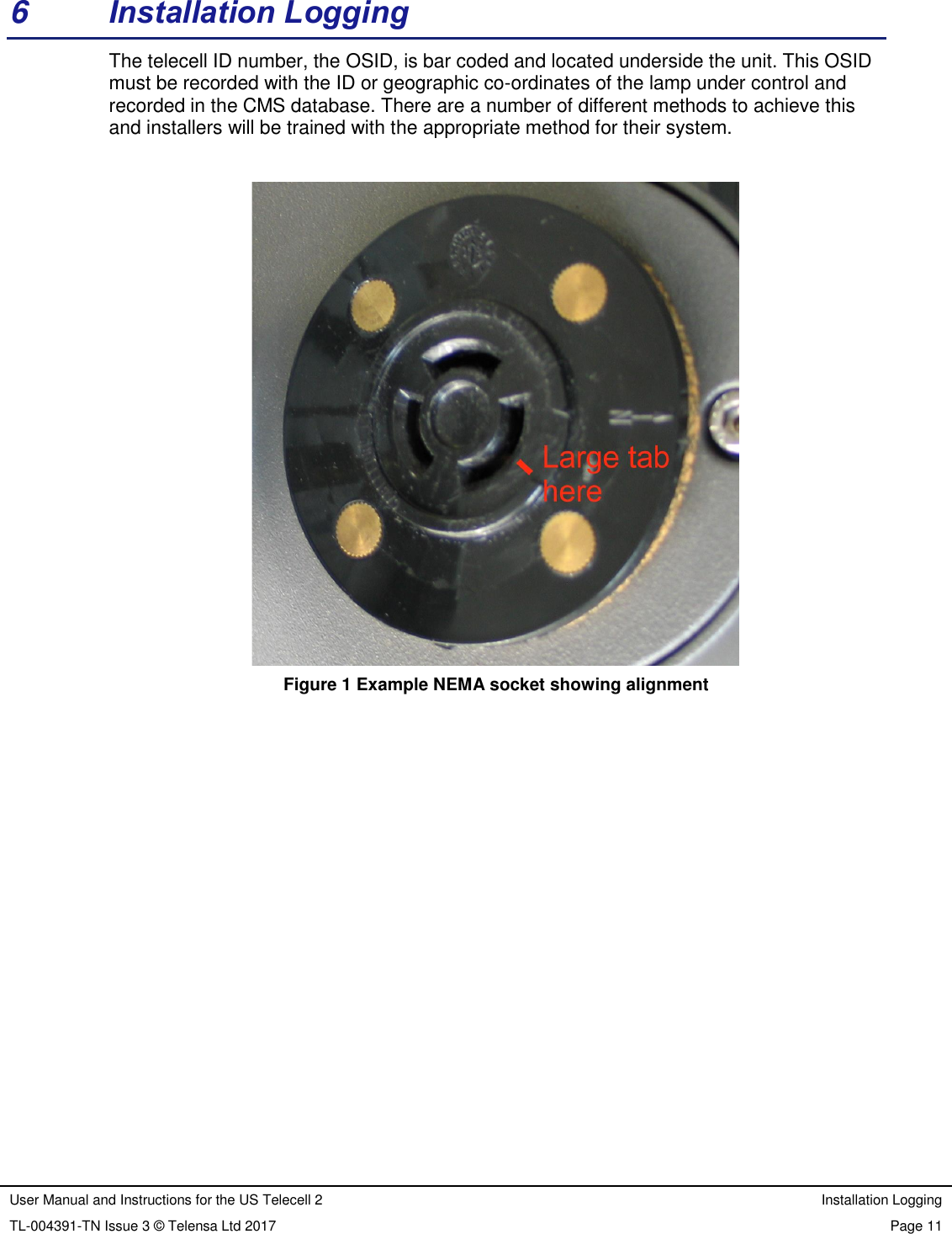
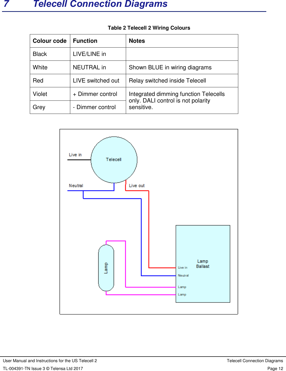
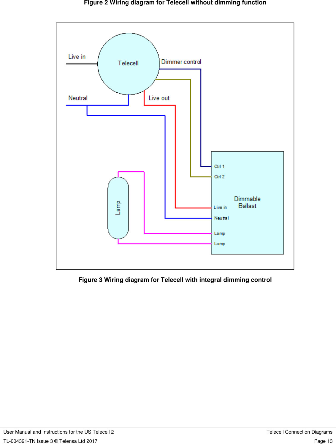
User Manual and Instructions for the US Telecell 2 Installation Instructions TL-004391-TN Issue 3 © Telensa Ltd 2017 Page 9  5  Installation Instructions Instructions for the installation of each of the different variants of Telecell are given below. Figure 2 shows a wiring diagram for a standard lamp with a non-dimmable ballast. Figure 3 shows dimming control using a dimmable ballast. Once installed and power is applied then the Telecell will automatically switch on to apply power to the lamp as an installation test. After one minute the lamp will be switched off and the Telecell will search and lock to the radio control signals from the system base stations. 5.1  Dimming Control NEMA Telecell T2A1N A dimming control Telecell will ONLY control a lamp that incorporates a 5 or 7 pin NEMA socket compliant with ANSI C136.41 2013. Insert unit into NEMA socket on street light ensuring the largest tab on the unit places into the largest tab recess on the NEMA socket on the street light. Turn by hand clockwise typically 30 degrees to lock in place. 5.2  Standard (Non-dimming) NEMA Telecell T2A1N Insert unit into NEMA socket on street light ensuring the largest tab on the unit places into the largest tab recess on the NEMA socket on the street light. Turn by hand clockwise typically 30 degrees to lock in place. 5.3  Post Top Telecell Type T2A1P This product is for installation within the photocontrol cavity of post top mounted heritage style lanterns. A separate “twig” style antenna must be installed with this Telecell, which has no internal antenna. First, do a trial installation of the Telecell in the lantern socket to check the location of the Telecell antenna socket. The antenna cable will have to reach to this socket. Mark a suitable location for the antenna on the outside of the luminaire and unplug and remove the Telecell.  Drill a half inch (12.5mm) hole in the luminaire case to mount the antenna and fit it in place. When fitting the antenna use all the waterproofing gaskets as provided and ensure that the metal grounding teeth on the antenna base make contact inside the luminaire case.  Fit the Telecell to its socket then attach the antenna lead connector to the Telecell antenna connector. Tighten by hand gently, there is no need for a high torque. If necessary, use a 5/16in wrench. The maximum torque is 3in-lbf. Use only antennas supplied by Telensa for this application, see Table 1. 5.4  Two-part Telecell Type T2A1U This product is intended for installation within a luminaire that has no NEMA socket, or insufficient space for fitting a NEMA socket. An external antenna must be fitted for the Telecell to function.
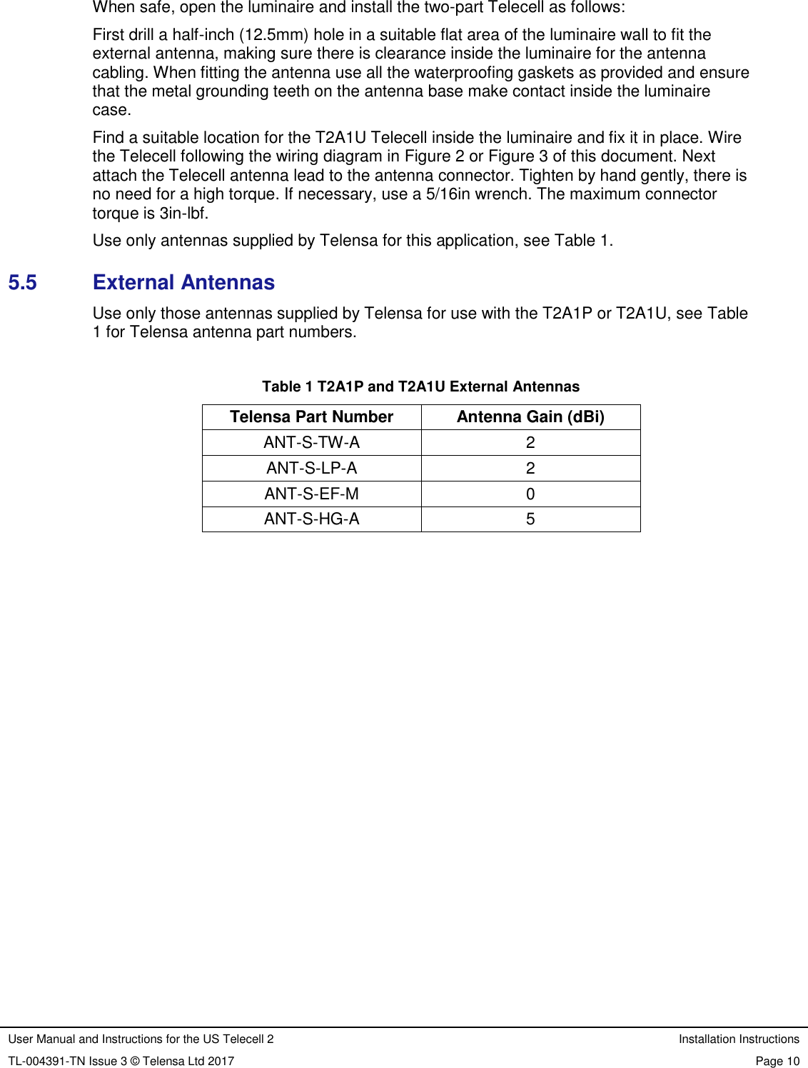
User Manual and Instructions for the US Telecell 2 Installation Instructions TL-004391-TN Issue 3 © Telensa Ltd 2017 Page 10  When safe, open the luminaire and install the two-part Telecell as follows: First drill a half-inch (12.5mm) hole in a suitable flat area of the luminaire wall to fit the external antenna, making sure there is clearance inside the luminaire for the antenna cabling. When fitting the antenna use all the waterproofing gaskets as provided and ensure that the metal grounding teeth on the antenna base make contact inside the luminaire case.  Find a suitable location for the T2A1U Telecell inside the luminaire and fix it in place. Wire the Telecell following the wiring diagram in Figure 2 or Figure 3 of this document. Next attach the Telecell antenna lead to the antenna connector. Tighten by hand gently, there is no need for a high torque. If necessary, use a 5/16in wrench. The maximum connector torque is 3in-lbf. Use only antennas supplied by Telensa for this application, see Table 1. 5.5  External Antennas Use only those antennas supplied by Telensa for use with the T2A1P or T2A1U, see Table 1 for Telensa antenna part numbers.  Table 1 T2A1P and T2A1U External Antennas Telensa Part Number Antenna Gain (dBi) ANT-S-TW-A 2 ANT-S-LP-A 2 ANT-S-EF-M 0 ANT-S-HG-A 5
User Manual and Instructions for the US Telecell 2 Installation Logging TL-004391-TN Issue 3 © Telensa Ltd 2017 Page 11  6  Installation Logging The telecell ID number, the OSID, is bar coded and located underside the unit. This OSID must be recorded with the ID or geographic co-ordinates of the lamp under control and recorded in the CMS database. There are a number of different methods to achieve this and installers will be trained with the appropriate method for their system.                  Figure 1 Example NEMA socket showing alignment
User Manual and Instructions for the US Telecell 2 Telecell Connection Diagrams TL-004391-TN Issue 3 © Telensa Ltd 2017 Page 12  7  Telecell Connection Diagrams  Table 2 Telecell 2 Wiring Colours Colour code Function Notes Black LIVE/LINE in  White  NEUTRAL in Shown BLUE in wiring diagrams Red LIVE switched out Relay switched inside Telecell Violet + Dimmer control Integrated dimming function Telecells only. DALI control is not polarity sensitive. Grey - Dimmer control
User Manual and Instructions for the US Telecell 2 Telecell Connection Diagrams TL-004391-TN Issue 3 © Telensa Ltd 2017 Page 13  Figure 2 Wiring diagram for Telecell without dimming function     Figure 3 Wiring diagram for Telecell with integral dimming control
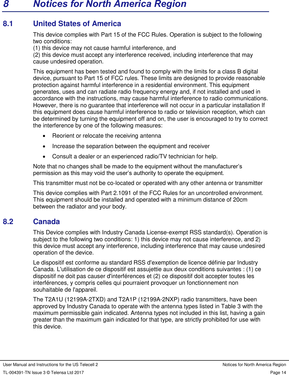
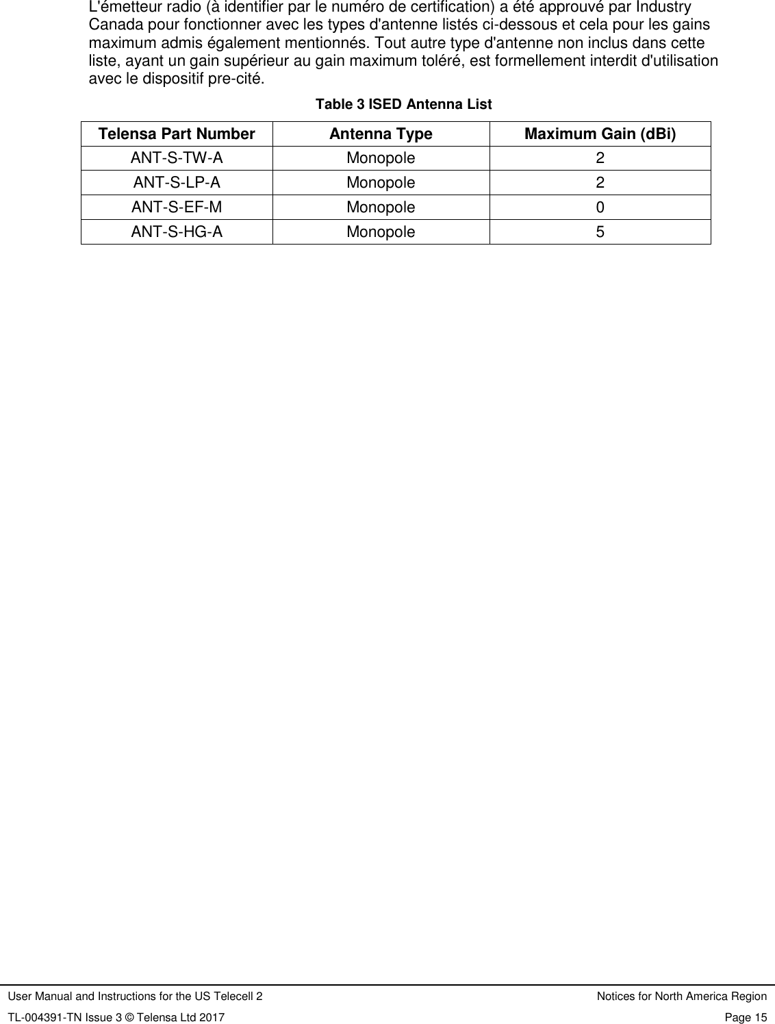
User Manual and Instructions for the US Telecell 2 Notices for North America Region TL-004391-TN Issue 3 © Telensa Ltd 2017 Page 14  8  Notices for North America Region 8.1  United States of America This device complies with Part 15 of the FCC Rules. Operation is subject to the following two conditions: (1) this device may not cause harmful interference, and (2) this device must accept any interference received, including interference that may cause undesired operation. This equipment has been tested and found to comply with the limits for a class B digital device, pursuant to Part 15 of FCC rules. These limits are designed to provide reasonable protection against harmful interference in a residential environment. This equipment generates, uses and can radiate radio frequency energy and, if not installed and used in accordance with the instructions, may cause harmful interference to radio communications. However, there is no guarantee that interference will not occur in a particular installation If this equipment does cause harmful interference to radio or television reception, which can be determined by turning the equipment off and on, the user is encouraged to try to correct the interference by one of the following measures:   Reorient or relocate the receiving antenna   Increase the separation between the equipment and receiver   Consult a dealer or an experienced radio/TV technician for help. Note that no changes shall be made to the equipment without the manufacturer’s permission as this may void the user’s authority to operate the equipment. This transmitter must not be co-located or operated with any other antenna or transmitter This device complies with Part 2.1091 of the FCC Rules for an uncontrolled environment. This equipment should be installed and operated with a minimum distance of 20cm between the radiator and your body. 8.2  Canada This Device complies with Industry Canada License-exempt RSS standard(s). Operation is subject to the following two conditions: 1) this device may not cause interference, and 2) this device must accept any interference, including interference that may cause undesired operation of the device. Le dispositif est conforme au standard RSS d'exemption de licence définie par Industry Canada. L'utilisation de ce dispositif est assujettie aux deux conditions suivantes : (1) ce dispositif ne doit pas causer d'interférences et (2) ce dispositif doit accepter toutes les interférences, y compris celles qui pourraient provoquer un fonctionnement non souhaitable de l'appareil. The T2A1U (12199A-2TXD) and T2A1P (12199A-2NXP) radio transmitters, have been approved by Industry Canada to operate with the antenna types listed in Table 3 with the maximum permissible gain indicated. Antenna types not included in this list, having a gain greater than the maximum gain indicated for that type, are strictly prohibited for use with this device.
User Manual and Instructions for the US Telecell 2 Notices for North America Region TL-004391-TN Issue 3 © Telensa Ltd 2017 Page 15  L'émetteur radio (à identifier par le numéro de certification) a été approuvé par Industry Canada pour fonctionner avec les types d'antenne listés ci-dessous et cela pour les gains maximum admis également mentionnés. Tout autre type d'antenne non inclus dans cette liste, ayant un gain supérieur au gain maximum toléré, est formellement interdit d'utilisation avec le dispositif pre-cité. Table 3 ISED Antenna List Telensa Part Number Antenna Type Maximum Gain (dBi) ANT-S-TW-A Monopole 2 ANT-S-LP-A Monopole 2 ANT-S-EF-M Monopole 0 ANT-S-HG-A Monopole 5

Navigation menu