Telensa 2TXD Telecell with dimming control and external antenna User Manual
Telensa Ltd. Telecell with dimming control and external antenna
Telensa >
Contents
- 1. User Manual
- 2. User Manual and Instructions
User Manual

COMMERCIAL IN CONFIDENCE
6LT071 02 13 Jun 2016 Page 1 of 10
QP4016 06 - Tech Note Template
Technical Note
Subject:
User Manual and instructions for Telecell 2 - N. America
Date:
13 Jun 2016
Document ref:
6LT071 02
Intentionally Blank
6LT071 02 13 Jun 2016
QP4016 07- Tech Note Template
Telensa
Telecell 2 User Manual
N. America Products
6LT071 02 13 Jun 2016
QP4016 07- Tech Note Template
Contents
CONTENTS ................................................................................................................................................................ 3
1 OPERATIONAL SAFETY NOTICES ............................................................................................................ 4
2 PRODUCT FUNCTION ................................................................................................................................... 4
3 TELECELL VARIANTS .................................................................................................................................. 4
4 SPECIFICATIONS ........................................................................................................................................... 4
4.1 US TYPE PRODUCTS, T2A… ....................................................................................................................... 4
4.2 NOTES ON DIMMING CONTROL OUTPUTS ...................................................................................................... 5
5 INSTALLATION INSTRUCTIONS ............................................................................................................... 5
5.1 DIMMING CONTROL NEMA TELECELL T2A1N .......................................................................................... 5
5.2 STANDARD (NON DIMMING) NEMA TELECELL T2A1N .............................................................................. 5
5.3 POST TOP TELECELL TYPE T2A1P ............................................................................................................... 5
5.4 TWO-PART TELECELL TYPE T2A1T ............................................................................................................. 6
6 INSTALLATION LOGGING .......................................................................................................................... 6
7 TELECELL CONNECTION DIAGRAMS .................................................................................................... 7
8 NOTICES FOR PRODUCTS OPERATED IN THE USA & CANADA .................................................... 10
6LT071 02 13 Jun 2016
QP4016 07- Tech Note Template
1 Operational Safety Notices
Installer
Installers must be suitably trained and qualified for electrical work, according to the laws and local codes
for the locality and country where the unit will be installed.
This unit must only be installed by personnel that have been trained by Telensa or their representatives to
carry out this work.
Power Supply
In the case of field installation the supply voltage present on the luminaire NEMA socket is hazardous
and all necessary precautions must be taken to ensure the safety of the installer. Isolate the supply to the
NEMA socket before removing an old photocontrol, and installing the telecell.
2 Product function
The telecell is a radio controlled device and will only function as part of a Telensa Central Management
System (CMS). Telecells are assigned to a specific CMS and cannot be transferred to another CMS
without being re-assigned by Telensa.
The telecell operating program is set by the CMS and dusk/dawn lamp switching is remote controlled
over the radio link by the associated CMS base stations. Typical maximum radio link distances are 2-
3km in a urban areas and 3-10km in rural areas, depending on the terrain.
3 Telecell Variants
There are two key variants of the Telecell 2 model; dimming control and standard / non-dimming
control. Dimming control products are identified by the text “0-10V & DALI” on the product label.
Telecell products are built and supplied to either the EU or US standards:
US product part numbers start with T2A…
The products are supplied with NEMA pin connections for insertion into the photocell socket on top of a
luminaire.
4 Specifications
4.1 US Type Products, T2A…
Electrical Parameters: Supply voltage: 100 - 277 VAC, 50-60Hz
Maximum switching current: 10A
Radio: Transmit Power: 100mW EIRP
Operating band: 915MHz license free ISM band
Operating Temperature: NEMA variants: -40 to 70 °C Ambient
6LT071 02 13 Jun 2016
QP4016 07- Tech Note Template
4.2 Notes on dimming control outputs
These notes apply to products with the integrated dimming control function:
Suitable for use with dimmable ballasts with an isolated or non-isolated control input
DALI or 0-10V control mode is auto-selected by the telecell by communicating with the
connected ballast.
0-10V control requires the normally fitted internal pull-up resistor in the ballast
DALI control includes the DALI supply function within the telecell and is suitable for
controlling from one to three dimmable ballasts.
5 Installation Instructions
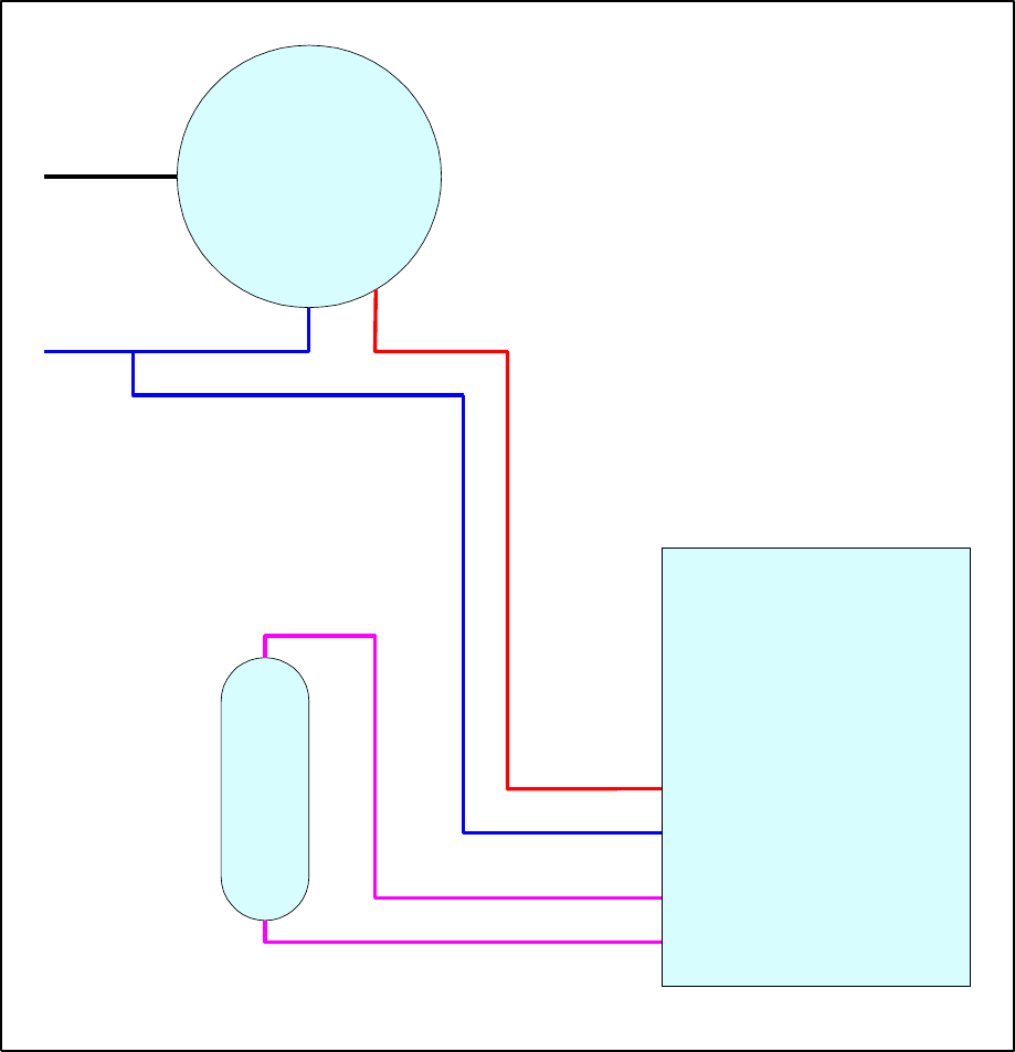
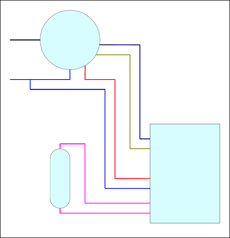
Instructions for the installation of each of the different variants of Telecell are given below. Figure 2
shows a wiring diagram for a standard lamp with a non-dimmable ballast. Figure 3 shows dimming
control using a dimmable ballast.
Once installed and power is applied then the telecell will automatically switch on to apply power to the
lamp as an installation test. After one minute the lamp will be switched off and the telecell will search
and lock to the radio control signals from the system base stations.
5.1 Dimming Control NEMA Telecell T2A1N
A dimming control telecell will ONLY control a lamp that incorporates a 5 or 7 pin NEMA socket
compliant with ANSI C136.41 2013.
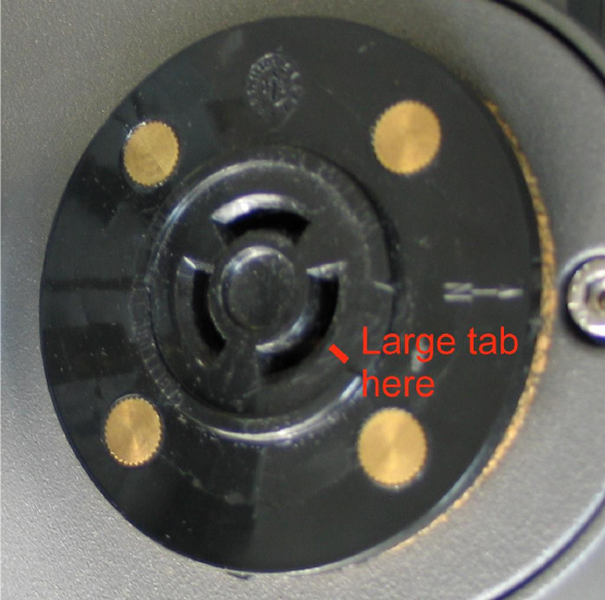
Insert unit into NEMA socket on street light ensuring the largest tab on the unit places into the largest tab
recess on the NEMA socket on the street light. Turn by hand clockwise typically 30 degrees to lock in
place.
5.2 Standard (non dimming) NEMA Telecell T2A1N
Insert unit into NEMA socket on street light ensuring the largest tab on the unit places into the largest tab
recess on the NEMA socket on the street light. Turn by hand clockwise typically 30 degrees to lock in
place.
5.3 Post Top Telecell type T2A1P
This product is for installation within the photocontrol cavity of post top mounted heritage style lanterns.
A separate “twig” style antenna must be installed with this telecell, which has no internal antenna.
First, do a trial installation of the telecell in the lantern socket to check the location of the telecell antenna
socket. The antenna cable will have to reach to this socket. Mark a suitable location for the antenna on
the outside of the luminaire and unplug and remove the telecell.
Drill a half inch (12.5mm) hole in the luminaire case to mount the antenna and fit it in place. When
fitting the antenna use all the waterproofing gaskets as provided and ensure that the metal grounding
teeth on the antenna base make contact inside the luminaire case.
Fit the telecell to its socket then attach the antenna lead connector to the telecell antenna connector.
Tighten by hand gently, there is no need for a high torque. If necessary, use a 5/16in wrench. The
maximum torque is 3in-lbf.
Use only the antenna supplied by Telensa for this application. Antenna part no: IN 1608.
6LT071 02 13 Jun 2016
QP4016 07- Tech Note Template
5.4 Two-part Telecell type T2A1T
This product is intended for installation within a luminaire that has no NEMA socket, or insufficient
space for fitting a NEMA socket. An external antenna must be fitted for the telecell to function.
When safe, open the luminaire and install the two-part telecell as follows:
First drill a half-inch (12.5mm) hole in a suitable flat area of the luminaire wall to fit the external
antenna, making sure there is clearance inside the luminaire for the antenna cabling. When fitting the
antenna use all the waterproofing gaskets as provided and ensure that the metal grounding teeth on the
antenna base make contact inside the luminaire case.
Find a suitable location for the two-part telecell inside the luminaire and fix it in place. Wire the telecell
following the wiring diagram in fig 2 or fig 3 of this document. Next attach the telecell antenna lead to
the antenna connector. Tighten by hand gently, there is no need for a high torque. If necessary, use a
5/16in wrench. The maximum connector torque is 3in-lbf.
Use only the antenna supplied by Telensa for this application. Antenna part no: IN 1608.
6 Installation logging
The telecell ID number, the OSID, is bar coded and located underside the unit. This OSID must be
recorded with the ID or geographic co-ordinates of the lamp under control and recorded in the CMS
database. There are a number of different methods to achieve this and installers will be trained with the
appropriate method for their system.
Fig 1: Example NEMA socket showing alignment

6LT071 02 13 Jun 2016
QP4016 07- Tech Note Template
7 Telecell Connection Diagrams
Refer to figures 2 and 3.
Colour code
Function
Notes
Black
LIVE/LINE in
White
NEUTRAL in
Shown BLUE in wiring diagrams
Red
LIVE switched out
Relay switched inside telecell
Violet
+ Dimmer control
Integrated dimming function telecells only.
DALI control is not polarity sensitive.
Grey
- Dimmer control
6LT071 02 13 Jun 2016
QP4016 07- Tech Note Template
Telecell
Lamp
Ballast
Lamp
Live in
Neutral Live out
Lamp
Lamp
Neutral
Live in
Figure 2: Wiring Diagram for Telecell - No Dimming Function
6LT071 02 13 Jun 2016
QP4016 07- Tech Note Template
Telecell
Dimmable
Ballast
Lamp
Live in
Neutral Live out
Dimmer control
Lamp
Lamp
Neutral
Live in
Ctrl 1
Ctrl 2
Figure 3: Wiring Diagram for Integral Dimming Control Telecell
6LT071 02 13 Jun 2016
QP4016 07- Tech Note Template
8 Notices for products operated in the USA & Canada
This device complies with Part 15 of the FCC Rules. Operation is subject to the following two
conditions:
(1) this device may not cause harmful interference, and
(2) this device must accept any interference received, including interference that may cause undesired
operation.
This equipment has been tested and found to comply with the limits for a class B digital device, pursuant
to Part 15 of FCC rules. These limits are designed to provide reasonable protection against harmful
interference in a residential environment. This equipment generates, uses and can radiate radio frequency
energy and, if not installed and used in accordance with the instructions, may cause harmful interference
to radio communications. However, there is no guarantee that interference will not occur in a particular
installation If this equipment does cause harmful interference to radio or television reception, which can
be determined by turning the equipment off and on, the user is encouraged to try to correct the
interference by one of the following measures:
Reorient or relocate the receiving antenna
Increase the separation between the equipment and receiver
Consult a dealer or an experienced radio/TV technician for help.
Note that no changes shall be made to the equipment without the manufacturer’s permission as this may
void the user’s authority to operate the equipment.
This transmitter must not be co-located or operated with any other antenna or transmitter
This device complies with Part 2.1091 of the FCC Rules for an uncontrolled environment. This
equipment should be installed and operated with a minimum distance of 20cm between the radiator and
your body.
This device complies with RSS-310 of Industry Canada. Operation is subject to the condition that this
device does not cause harmful interference.