Telensa TBSA1 Part 15 Spread Spectrum Transmitter User Manual for the BS A US Basestation
Telensa Ltd. Part 15 Spread Spectrum Transmitter for the BS A US Basestation
Telensa >
User Manual

COMMERCIAL IN CONFIDENCE
LLT289 02 14 Jun 2012 Page 1 of 7
QP4016 09- Tech Note Template
Title:
User Manual for the BS-A US Basestation
Date:
14 Jun 2012
Document ref:
LLT289 02
Telensa
Lighting Control
COMMERCIAL IN CONFIDENCE
LLT289 02 14 Jun 2012 Page 2 of 7
QP4016 09- Tech Note Template
Contents
OPERATIONAL SAFETY NOTICES ..................................................................................................................... 3
INSTALLER ................................................................................................................................................................ 3
RADIO TRANSMITTER - CAUTION .......................................................................................................................... 3
POWER SUPPLY CONNECTION ................................................................................................................................... 3
INTERNAL POWER SUPPLY ......................................................................................................................................... 3
FCC STATEMENT .................................................................................................................................................... 3
1 ACCESSORIES REQUIRED ........................................................................................................................... 4
2 INSTALLATION PROCEDURE .................................................................................................................... 4
3 BS-A SPECIFICATIONS ................................................................................................................................. 5
3.1 ELECTRICAL PARAMETERS: ......................................................................................................................... 5
3.2 ENVIRONMENTAL ........................................................................................................................................ 5
3.3 SAFETY COMPLIANCE .................................................................................................................................. 5
4 EQUIPMENT DESCRIPTION ........................................................................................................................ 6
5 CONTACT DETAILS ....................................................................................................................................... 7

COMMERCIAL IN CONFIDENCE
LLT289 02 14 Jun 2012 Page 3 of 7
QP4016 09- Tech Note Template
Operational Safety Notices
Installer
Installers must be suitably trained and qualified for electrical work, according to the laws and local codes
for the locality and country.
This unit must only be installed by personnel that have been trained by Telensa or their representatives to
carry out this work.
Radio Transmitter - CAUTION
The base station unit described in this guide emits radio frequency energy through its antenna. Although
the power level is low, concentrated energy from a directional antenna may pose a health hazard. Only
outdoor antennas certified with this transmitter should be used and must be installed to provide a
separation distance of at least 20.5cm (8 inches) from all persons who could be nearby when the base
station is operating.
Power Supply Connection
The supply voltage for the base station is hazardous and all necessary precautions must be taken to
ensure the safety of the installer, maintenance staff and any person that may come into contact with the
unit or its wiring.
The supply connection must be protected by an MCB or fuse, rated at 6A maximum
Supply connections must be made water and weatherproof against the weather conditions encountered at
the location area.
Internal power supply
Note that the operating voltages within the base station compartment are at 24V DC or below.
FCC Statement
This equipment complies with Part 15 of the FCC Rules. Operation is subject to the following two
conditions: (1) This device may not cause harmful interference, and (2) this device must accept any
interference received, including interference that may cause undesired operation.
This equipment complies with FCC radiation exposure limits set forth for an uncontrolled environment.
Installers and end users must follow the specific installation and operating instructions for satisfying RF
exposure compliance. The antenna used with this transmitter must be maintained at least 20.5 cm (8
inches) from any person when the equipment is operating.
More information on RF exposure is available on the Internet at:
www.fcc.gov/oet/info/documents/bulletins.
This equipment is specifically designed to be used under Section 15.247 of the FCC Rules and
Regulations. Any unauthorised modification or changes to this device without the express approval of
Telensa Limited may void the user’s authority to operate this device.
Furthermore, this device is intended to be used only when installed in accordance with the instructions
outlined in this manual. Failure to comply with these instructions may also void the user’s authority to
operate this device.

COMMERCIAL IN CONFIDENCE
LLT289 02 14 Jun 2012 Page 4 of 7
QP4016 09- Tech Note Template
1 Accessories required
Antenna, 890-930MHz, 8dBi gain ref: Jaybeam 7556910
Do not use any other antenna type!
Antenna fixing bolts x 4
Mounting buckles x 2
Mounting clip to suit pole diameter or mounting strap, stainless steel x 2
Bird repelling spikes x 3
Bird repelling spike mounting moulding x 1
Fixing screws for above x 2
Door key
Tools as required
2 Installation Procedure
Unpack the unit and inspect for exterior damage
Attach the pole antenna to the side of the unit using the four supplied M5 fixing bolts
Connect the antenna lead to the large antenna socket at the bottom of the case and tighten. Push
the flexible weather protection sleeve fully up and over the antenna connection
Fit the bird spike retaining moulding to the top using the two fixing screws and clip the three bird
spikes into the moulding
Cut the mains power lead to the desired length for the installation, strip back and fit a
weatherproof power connector
Isolate and test the source mains supply and prepare the connection for the base station as
appropriate for the installation. Note that a local circuit isolator and circuit protection of 6A max
must be used for connection to the base station
Prepare the mounting buckles and mounting clips at the rear of the unit
Fit the base station unit to the mounting pole or lighting column using the mounting clips.
Note: Make sure that the light sensor (white lens) is above the luminaire of the lighting column
to prevent faulty operation due to light leakage
Tighten and secure the mounting clips
Make the power supply connection
Terminate the local internet connection using the weatherproof RJ45 connector and plug into the
comms connector at the bottom of the unit
Open the door of the case and plug the back-up battery connector into its PCB mounted
connector. LEDs should begin blinking at the top of the PCB
Close the case and switch on the main supply power
Check the function of the unit by logging in to the PLANet system as per the system training.

COMMERCIAL IN CONFIDENCE
LLT289 02 14 Jun 2012 Page 5 of 7
QP4016 09- Tech Note Template
3 BS-A Specifications
3.1 Electrical Parameters:
Supply Voltage: 102 - 276 VAC, 50-60Hz
Power Consumption: 20W max (<1A, 120-240V AC)
Radio Transmit Power: 4W EIRP using the specified antenna
NiMh backup battery time: Typically 30-60 minutes after loss of power
3.2 Environmental
Operating Temperature: -30 to 60 °C Ambient
Protection Rating: IP65
3.3 Safety Compliance
This equipment complies with the electrical safety requirements of the international safety standard IEC
60950.
COMMERCIAL IN CONFIDENCE
LLT289 02 14 Jun 2012 Page 6 of 7
QP4016 09- Tech Note Template
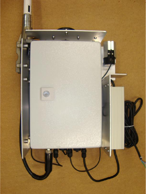
4 Equipment Description
The Telensa basestation (BS) contains a single board computer, radio transceiver, power supply and
interface PCB with backup battery. The unit is directly powered off the mains AC supply and uses an
Ethernet port for connection to the internet. The internet connection is encrypted over a VPN (Virtual
Private Network) to a remote server. The remote server is accessed using the Telensa PLANet interface.
On the top of the unit is the GPS sensor used for location and timing, and to the top right is the light
sensor used for controlling the telecell switching.
Telensa Basestation Exterior - Model: BS-A

COMMERCIAL IN CONFIDENCE
LLT289 02 14 Jun 2012 Page 7 of 7
QP4016 09- Tech Note Template
5 Contact Details
Address: Telensa Ltd,
Plextek Building,
London Road,
Great Chesterford,
Essex,
CB10 1NY.
UK.
Telephone: +44 (0) 1799 533200
Fax: +44 (0) 1799 533201
Email: enquiries@telensa.com
Website: http://www.telensa.com