Telephonics Wireless 8504HI0001000 GSM850 NanoCell User Manual Theory of Operations
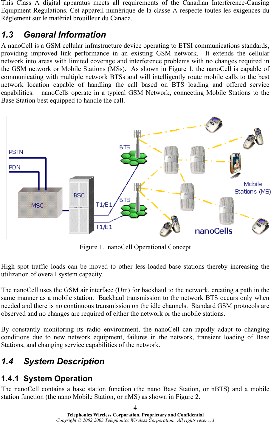
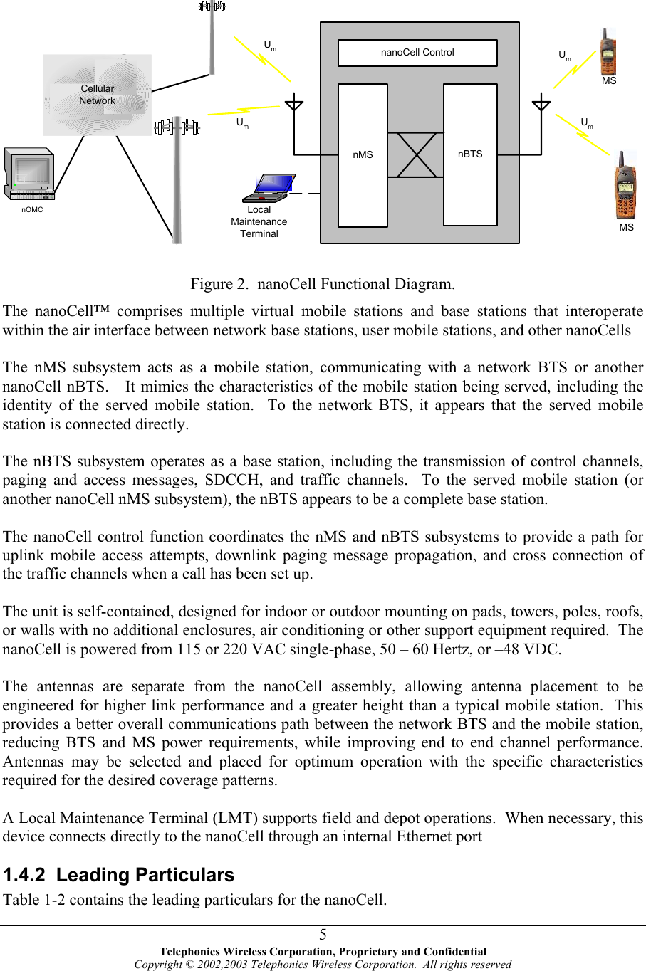
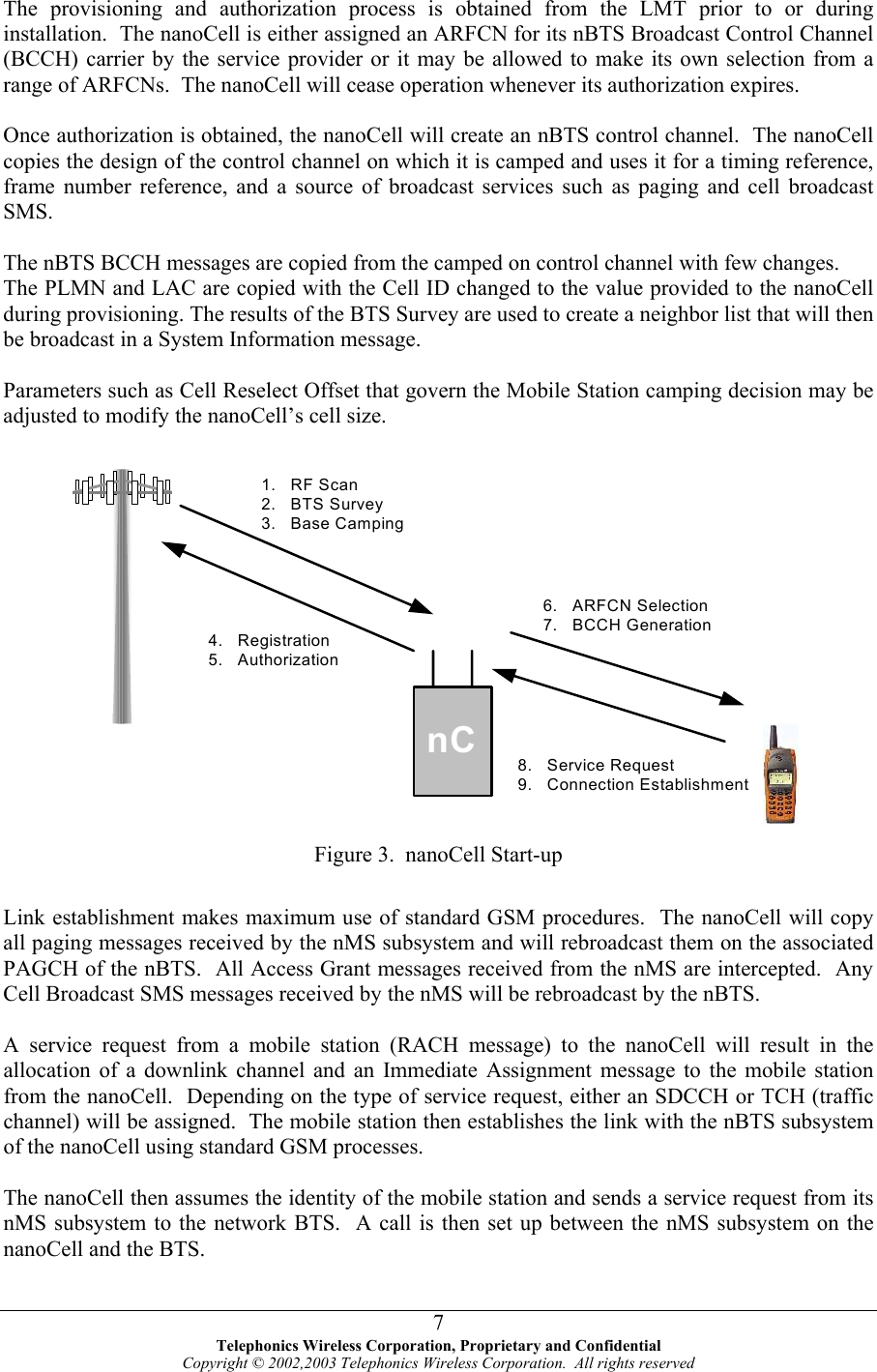
Telephonics Wireless Corporation GSM850 NanoCell Theory of Operations
UserManual.wiki
>
Telephonics Wireless
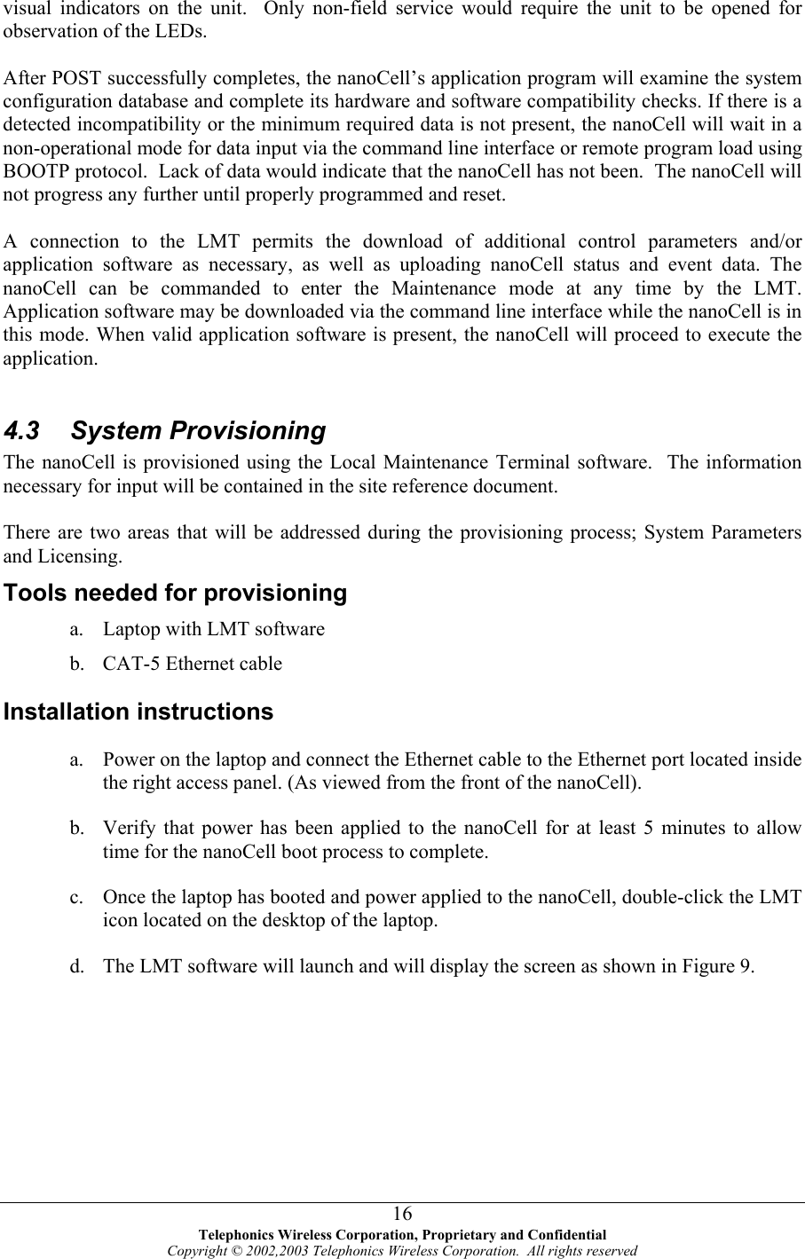
>
8504HI0001000 User Manual
users manaul
Navigation menu
Upload a User Manual
Namespaces
Wiki Guide
HTML
PDF
Info
Views
User Manual
Discussion / Help
Navigation