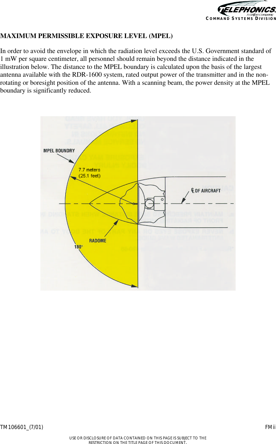
Telephonics MCB-RT-1601 Color Weather and Search and Rescue Radar User Manual 106601 601
Telephonics Corporation Color Weather and Search and Rescue Radar 106601 601
UserManual.wiki
>
Telephonics
>
MCB-RT-1601 User Manual
>
installation manual
Contents
1.
maintenance manual
2.
installation manual
3.
manual
installation manual
Navigation menu
Upload a User Manual
Namespaces
Wiki Guide
HTML
PDF
Info
Views
User Manual
Discussion / Help
Navigation
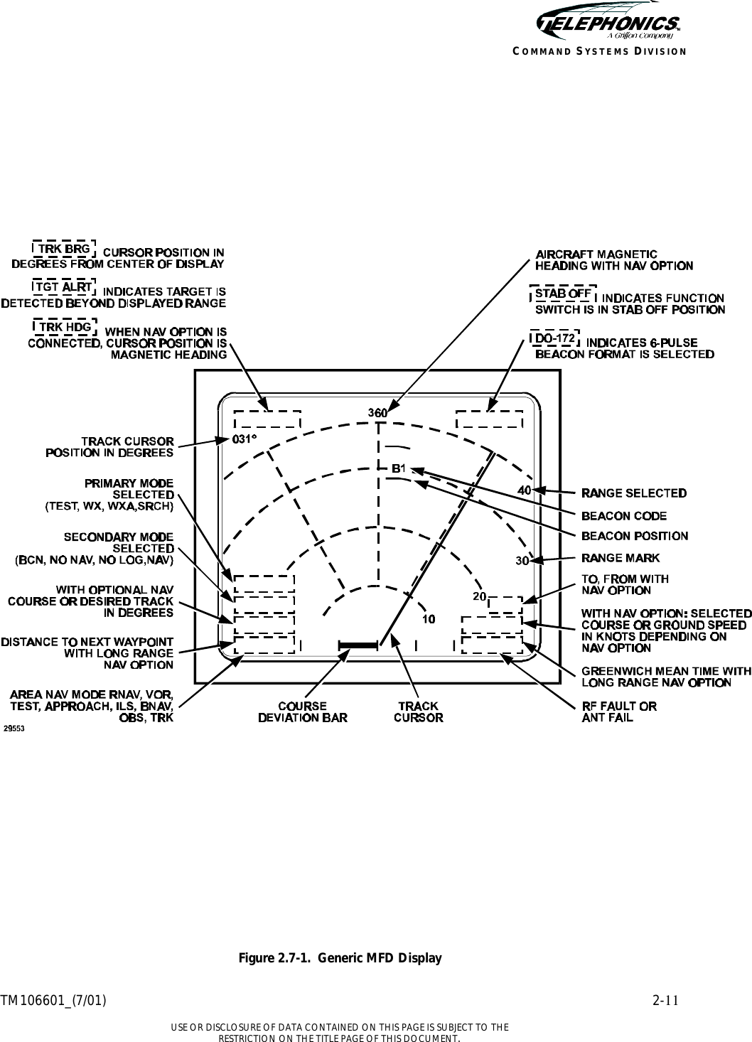
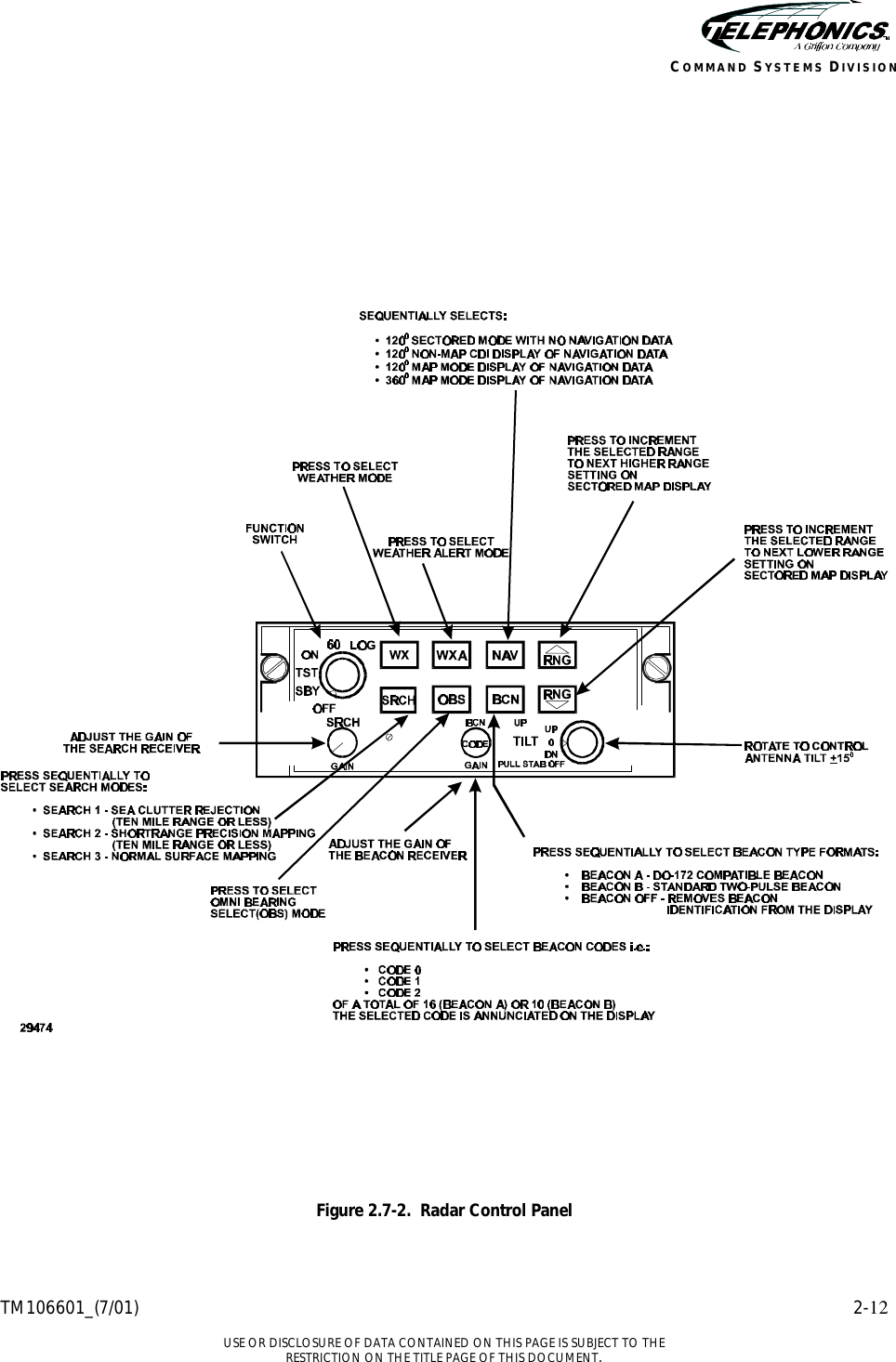
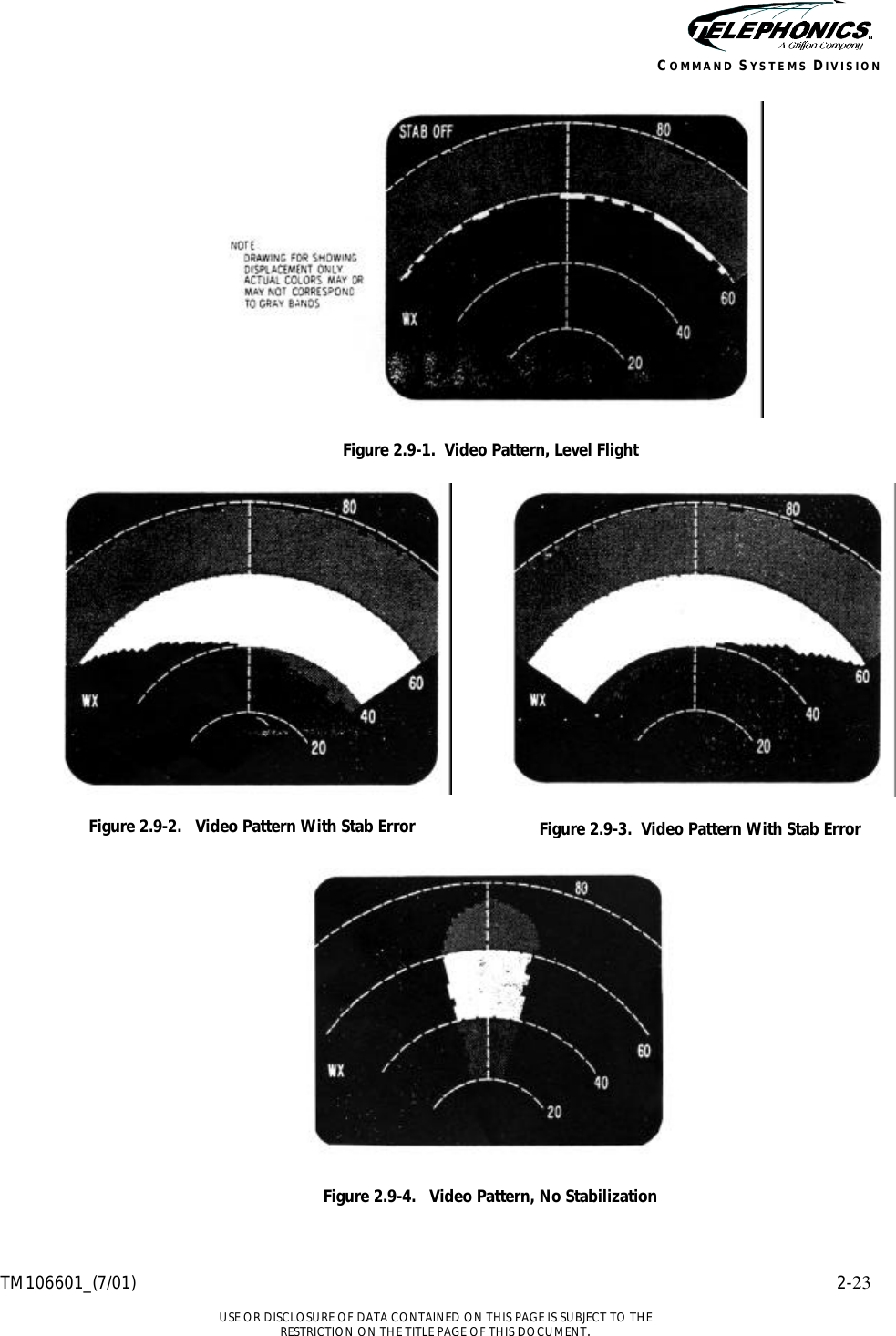
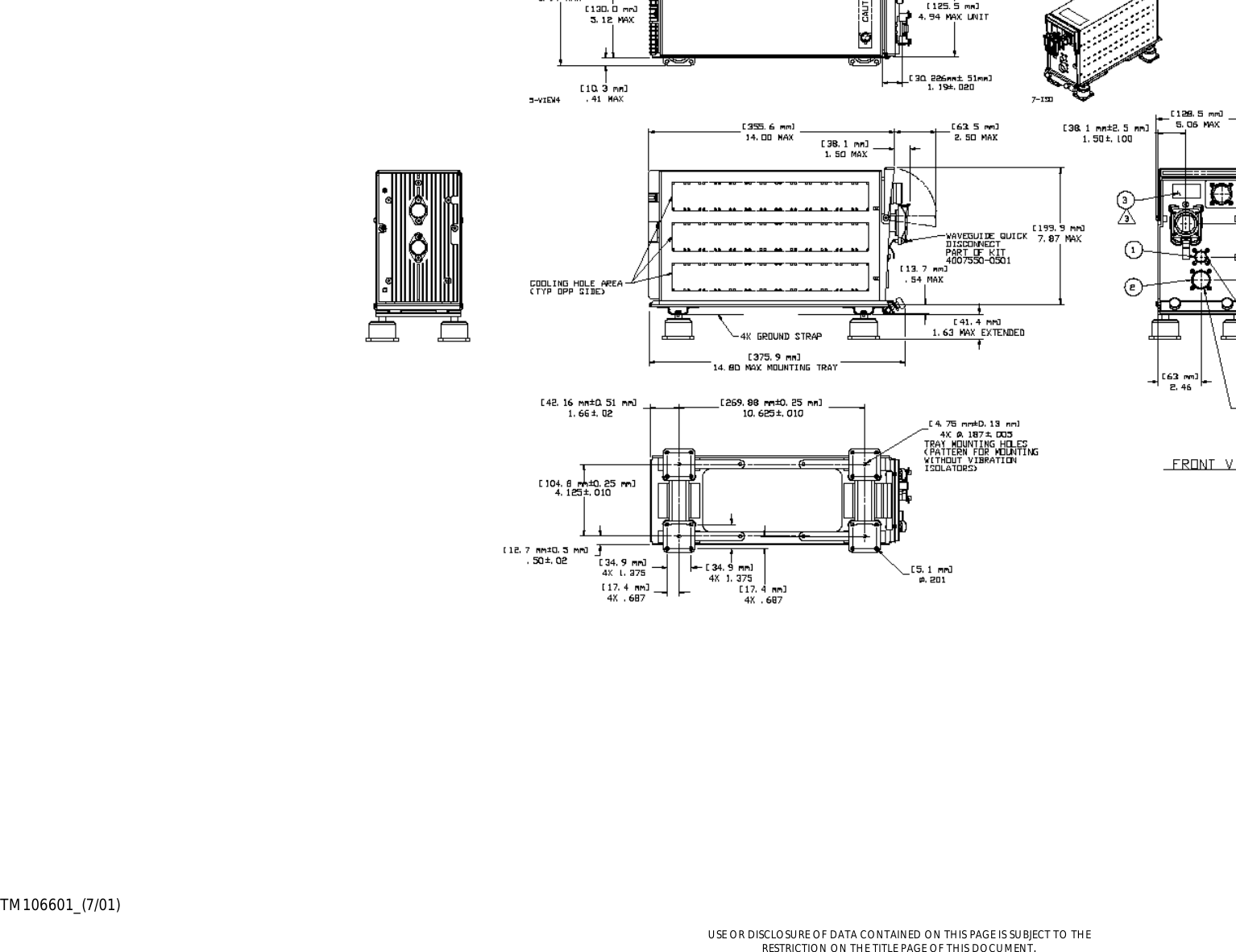
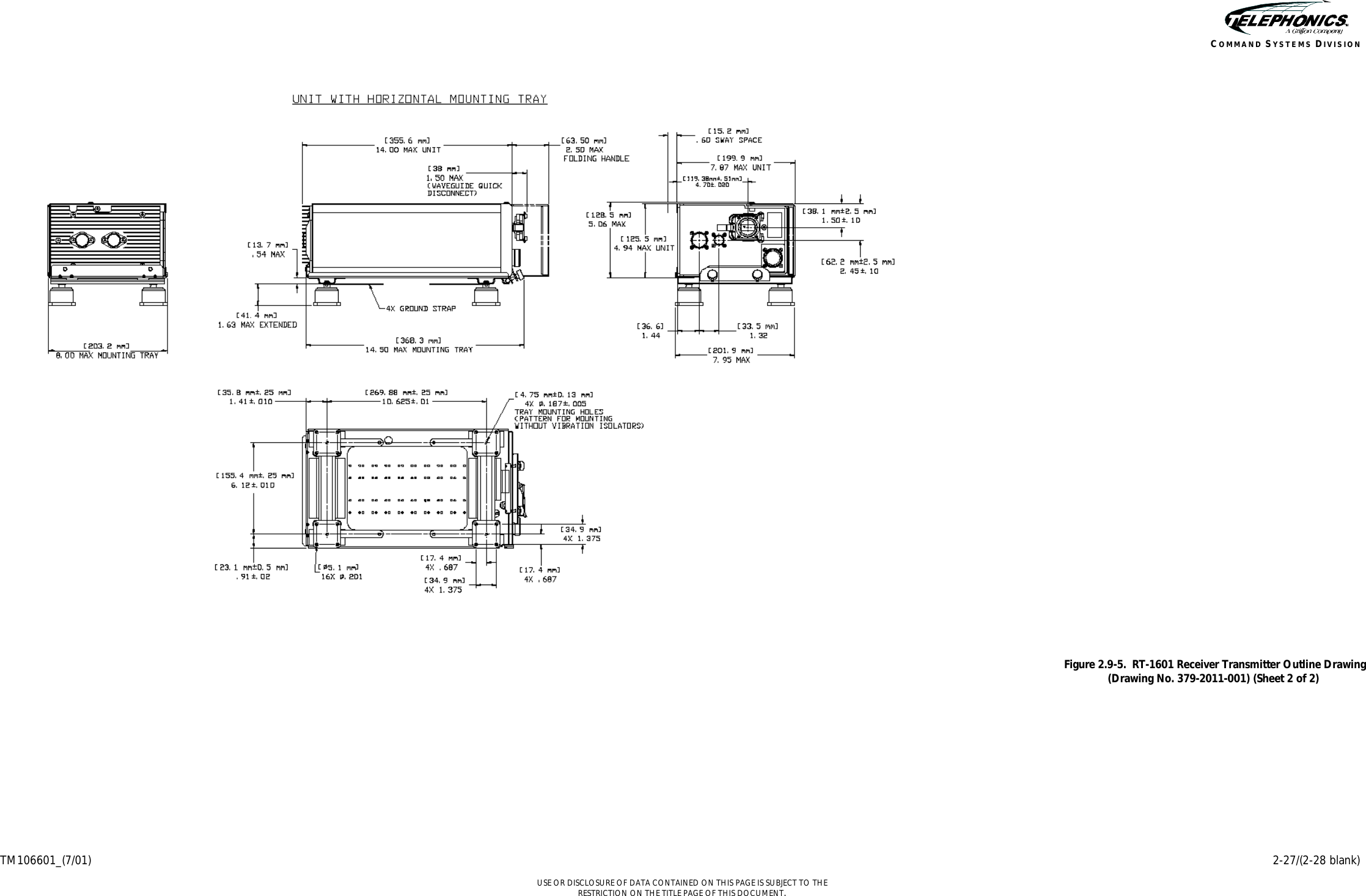
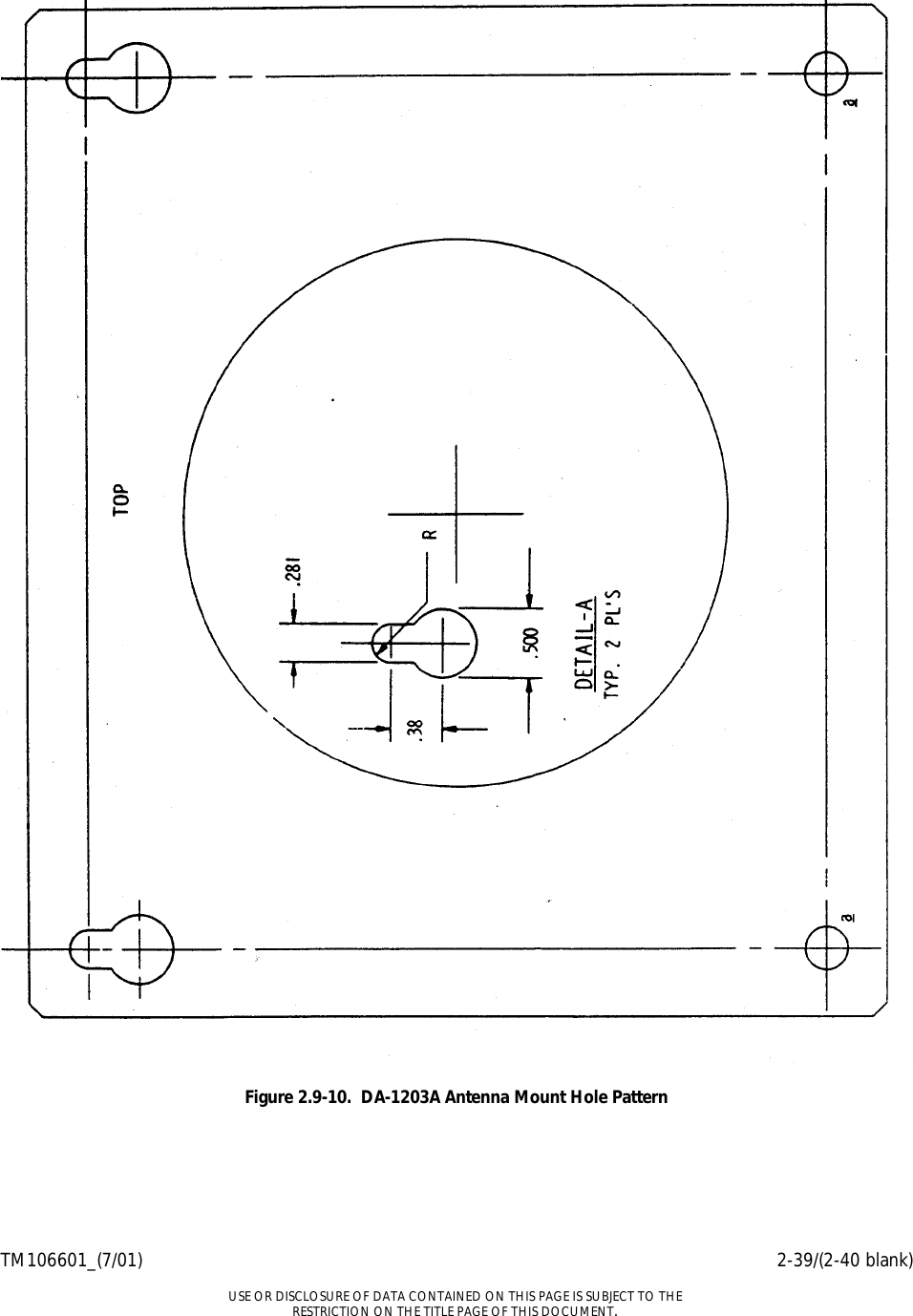
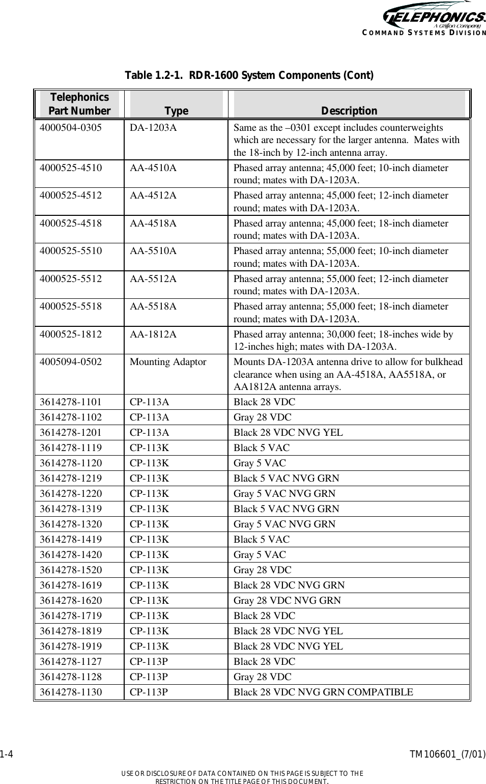
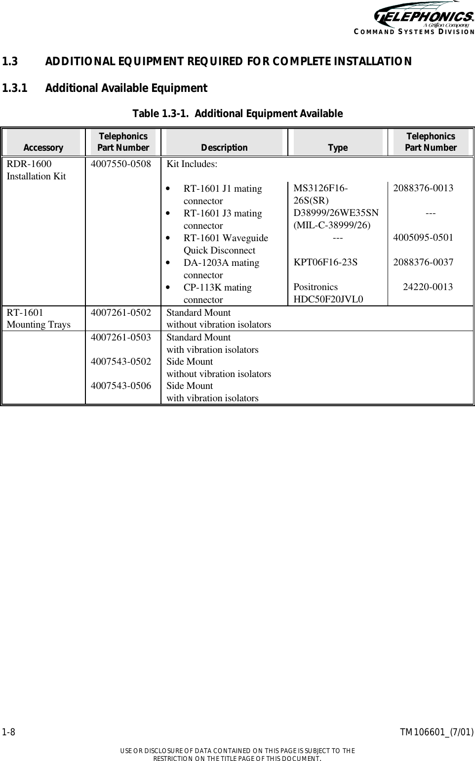
![TM106601_(7/01) iii USE OR DISCLOSURE OF DATA CONTAINED ON THIS PAGE IS SUBJECT TO THE RESTRICTION ON THE TITLE PAGE OF THIS DOCUMENT. COMMAND SYSTEMS DIVISION TABLE OF CONTENTS [continued] PARAGRAPH TITLE PAGE 1.6.4.10 DO-172 Six-Pulse Beacon Interrogation........................1-Error! Bookmark not defined. 1.6.4.11 Target Alert Function......................................................................................................1-31 1.7 ASSOCIATED PUBLICATIONS ...........1-3ERROR! BOOKMARK NOT DEFINED. CHAPTER 2. INSTALLIATION.......................................................................................................... 2-1 2.1 GENERAL........................................................................................................................2-1 2.2 UNPACKING ...................................................................................................................2-1 2.3 PRE-INSTALLATION CHECK......................................................................................2-1 2.4 INSTALLATION PLANNING........................................................................................2-1 2.4.1 Outline and Interconnect Drawings ..................................................................................2-1 2.4.2 Location of Equipment......................................................................................................2-2 2.4.3 Primary Power Requirements ...........................................................................................2-2 2.4.4 Roll and Pitch Information................................................................................................2-2 2.5 INSTALLATION OF SYSTEM COMPONENTS .........................................................2-3 2.5.1 Radar Antenna...................................................................................................................2-3 2.5.1.1 Assembly of Antenna Array and Antenna Drive Assembly Procedure............................2-3 2.5.1.2 Installation of DA-1203A Antenna Assembly Procedure................................................2-3 2.6 POST-INSTALLATION CHECK ...................................................................................2-4 2.6.1 Installation of RT-1601 Receiver Transmitter .................................................................2-5 2.6.2 Installation of CP-113 Radar Control Panel.....................................................................2-5 2.6.3 Installation of Waveguide and Cables ..............................................................................2-6 2.6.3.1 Cabling..............................................................................................................................2-6 2.6.3.2 Waveguide.........................................................................................................................2-6 2.7 POST-INSTALLATION CHECK ...................................................................................2-8 2.7.1 Visual Inspection Procedure .............................................................................................2-9 2.7.2 Control Panel and MFD Display Check Procedure in Test Mode....................................2-9 2.7.3 Antenna Stabilization Check...........................................................................................2-10 2.7.4 Antenna Checkout Aids ..................................................................................................2-13 2.7.4.1 Tilt Check Procedure.......................................................................................................2-13 2.7.4.2 Pitch Calibration Check Procedure.................................................................................2-13 2.7.4.3 Roll Calibration Check Procedure ..................................................................................2-14 2.7.5 RF Operation Check Procedure ......................................................................................2-15 2.7.6 Interference Test Procedure ............................................................................................2-16 2.8 PREFLIGHT CHECK AND FLIGHT CHECK PROCEDURES................................2-16 2.8.1 Preflight Check Procedure ..............................................................................................2-16 2.8.1.1 Single Indicators..............................................................................................................2-16 2.8.1.2 Multiple Displays............................................................................................................2-19 2.8.2 Flight Check Procedure...................................................................................................2-19 2.8.2.1 Check Test Pattern..........................................................................................................2-19 2.8.2.2 Check And Adjust Antenna Stabilization.......................................................................2-20 2.8.2.3 Check Weather Alert Mode ............................................................................................2-21 2.8.2.4 Check Target Alert..........................................................................................................2-21 2.8.2.5 Testing Completed..........................................................................................................2-22 2.9 ILLUSTRATIONS AND DRAWINGS.........................................................................2-22](https://usermanual.wiki/Telephonics/MCB-RT-1601.installation-manual/User-Guide-271075-Page-13.png)
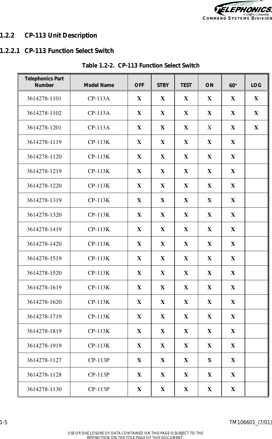
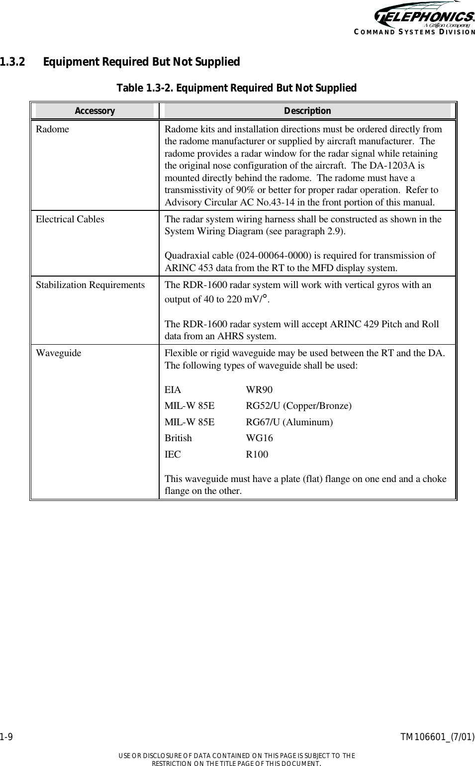
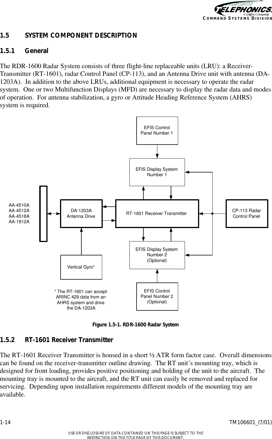
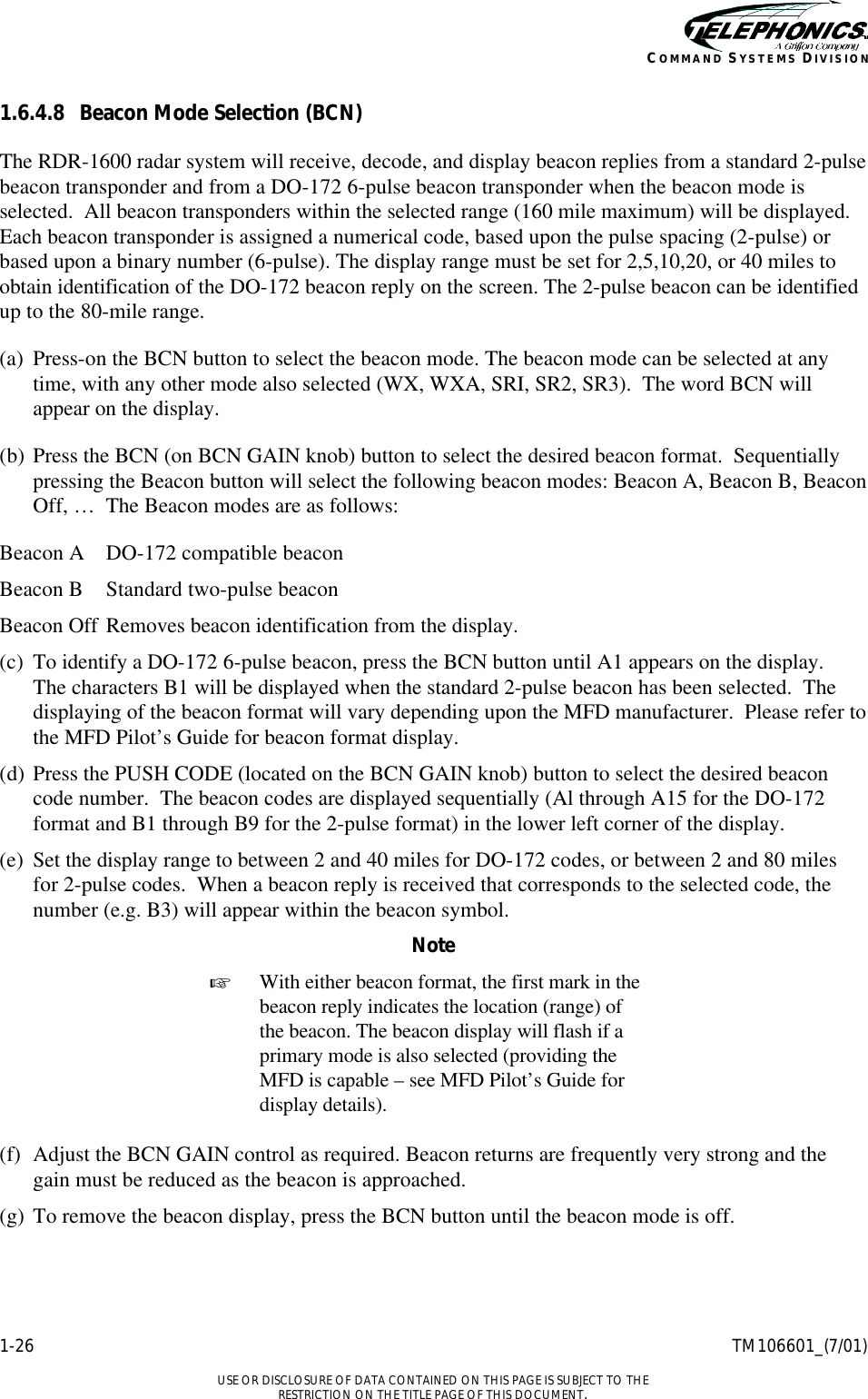
![1-10 TM106601_(7/01) USE OR DISCLOSURE OF DATA CONTAINED ON THIS PAGE IS SUBJECT TO THE RESTRICTION ON THE TITLE PAGE OF THIS DOCUMENT. COMMAND SYSTEMS DIVISION 1.4 LEADING PARTICULARS 1.4.1 RDR-1600 Radar System Table 1.4-1. RDR-1600 Radar System Characteristic Description System Power Requirements System 5.0 Amps at 28 VDC. 3.0 VA at 115 VAC, 400 Hz (power factor 0.68) Panel Lighting 0.4 Amps at 5 Volt 0.1 Amps at 28 VDC Display Range / Range Marks [nm] 0.5 0.25, 0.5 1 0.5, 1 2 0.5, 1, 1.5, 2 5 1.25, 2.5, 3.75, 5 10 2.5, 5, 7.5, 10 20 5, 10, 15, 20 40 10, 20, 30, 40 80 20, 40, 60, 80 160 40, 80, 120, 160 240 60, 120, 180, 240 Minimum Tracking Range 500 feet Displayed Modes of Operation Standby (STBY) Test (TEST) Weather (WX) Weather Alert (WXA) Search 1 (SR1) Search 2 (SR2) Search 3 (SR3) System Self Test Initiated BIT Test Mode – The display will show the radar test pattern. Continuous BIT Monitors faults in the Receiver Transmitter, Antenna Drive, and Radar Control Panel. Transmitted Power 10 KW Peak Power Transmit and Receive Frequencies Transmit Receive Weather Mode 9375 ± 5 MHz 9375 ± 5 MHz Search Mode 9375 ± 5 MHz 9375 ± 5 MHz Beacon Mode 9375 ± 5 MHz 9310 ± 5 MHz](https://usermanual.wiki/Telephonics/MCB-RT-1601.installation-manual/User-Guide-271075-Page-27.png)
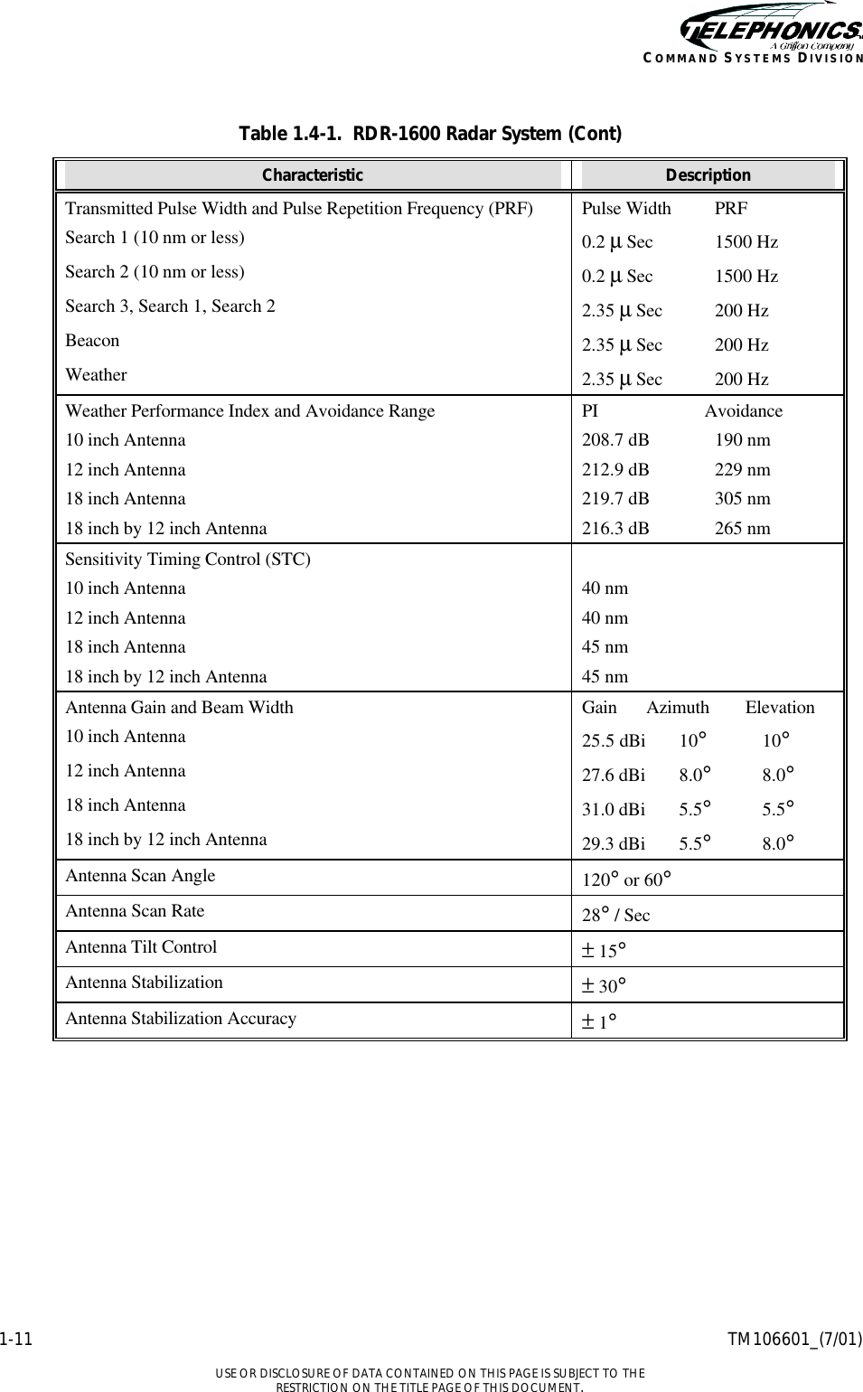
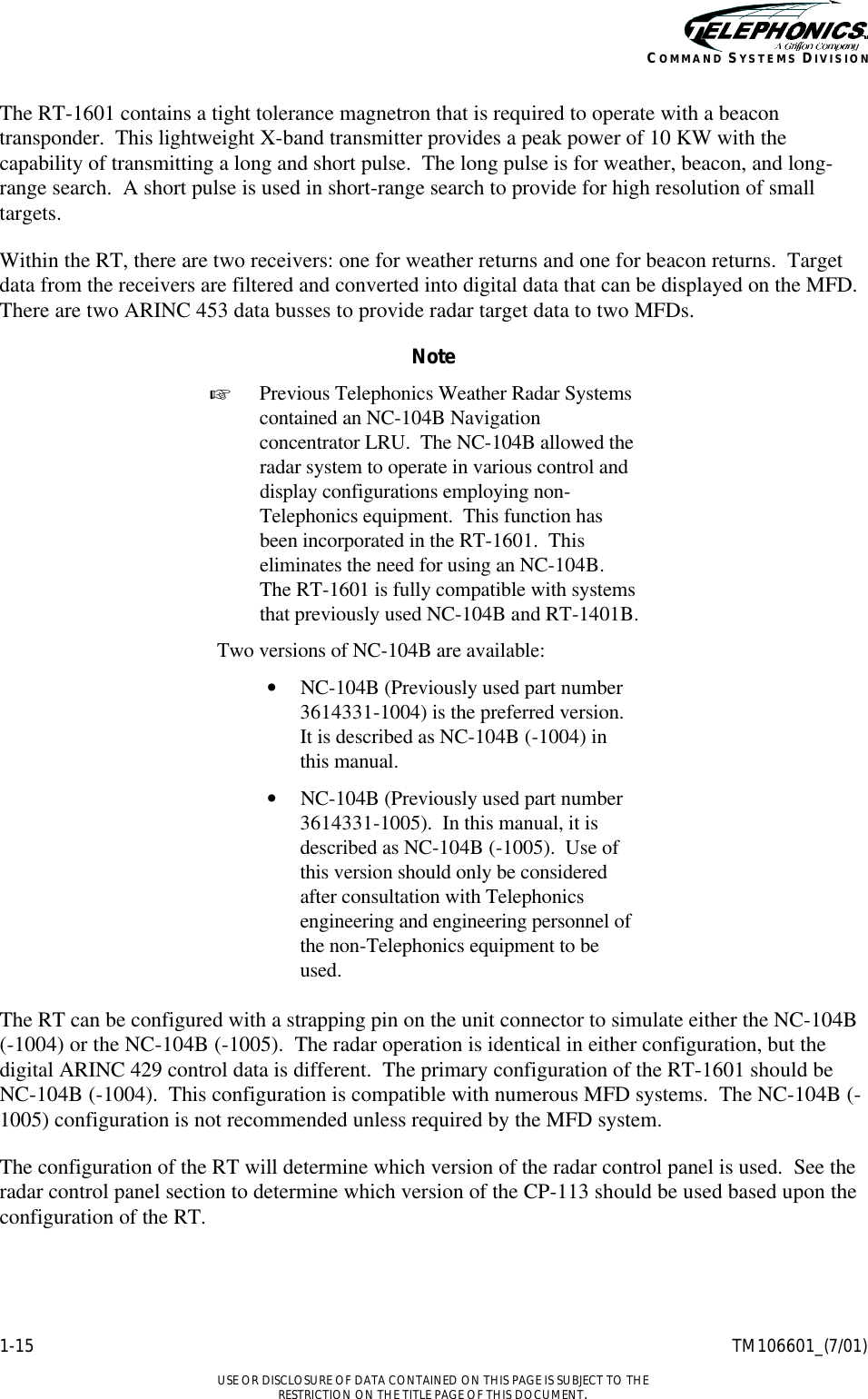
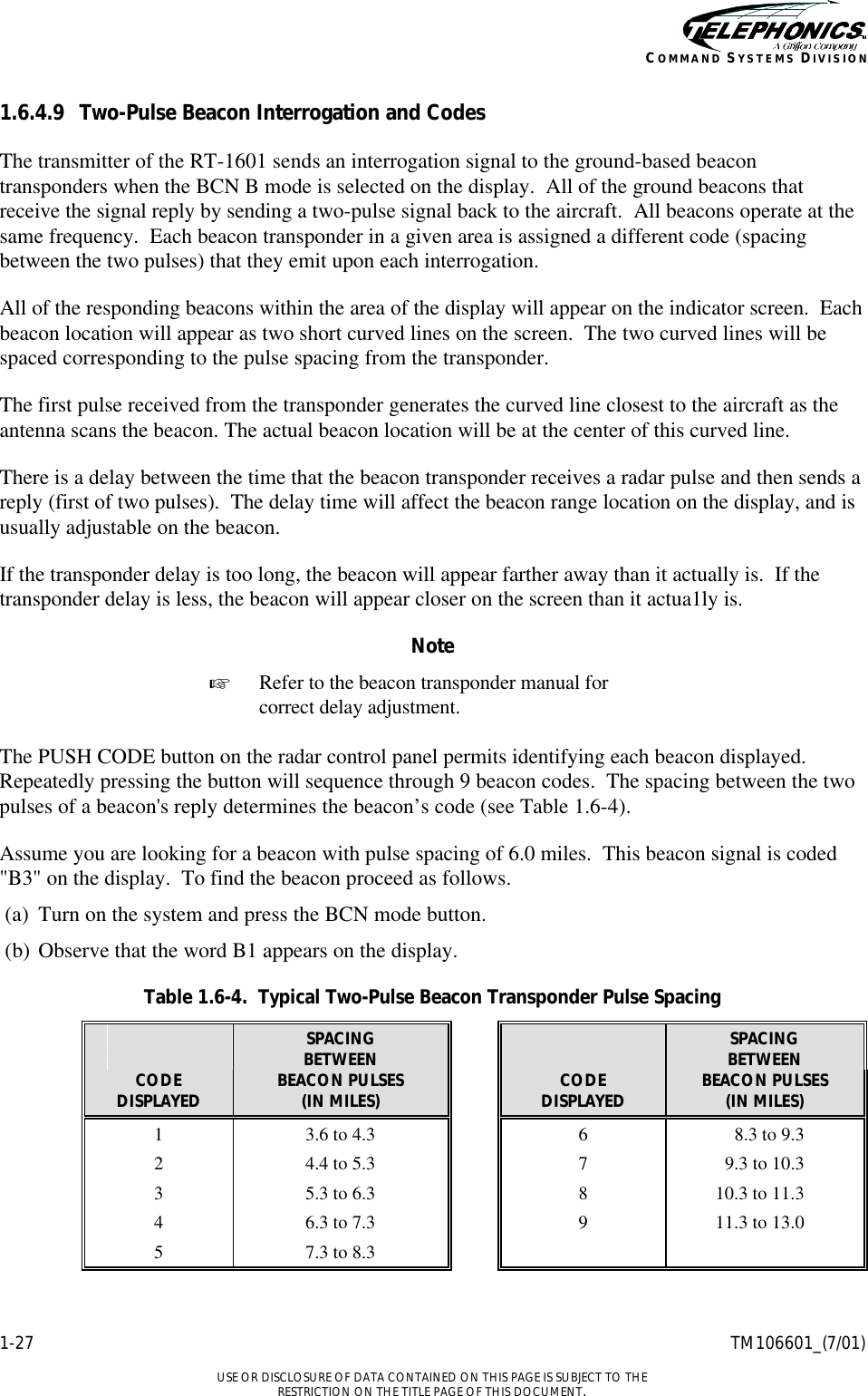
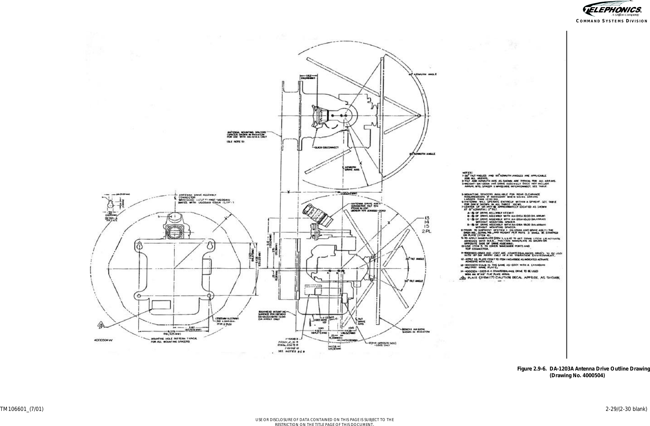
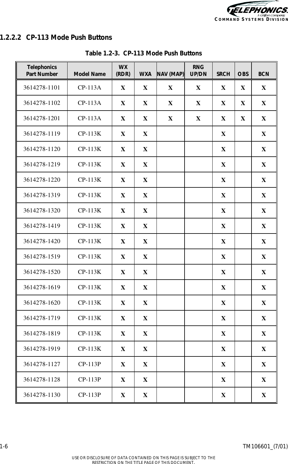
![1-12 TM106601_(7/01) USE OR DISCLOSURE OF DATA CONTAINED ON THIS PAGE IS SUBJECT TO THE RESTRICTION ON THE TITLE PAGE OF THIS DOCUMENT. COMMAND SYSTEMS DIVISION 1.4.2 RT-1601 Receiver Transmitter Table 1.4-2. Leading Particulars RT-1601 Receiver Transmitter Characteristic Description Size Short ½ ATR Weight (maximum) 17.3 lbs (7.8 kg) Mounting Mounting Tray Pressurization None Required TSO C63c, Class 7 C102 RTCA Documents DO-172 DO-173 DO-178A, Level 2 DO-160A DO-160A Environmental Categories D1A/MON/XXXXXXBBABA DO-160C Environmental Categories [D1]WBA(MON)XXXXXXBBABAAAXXX 1.4.3 DA-1203A Antenna Drive Table 1.4-3. DA-1203A Antenna Drive Characteristic Description Size See Figure 2.9-6 DA-1203A Antenna Drive Outline Drawing Weight (maximum) See Figure 2.9-6 DA-1203A Antenna Drive Outline Drawing Mounting Directly to bulkhead, inverted or standard, 18” and 18”x12” antennas require special mounting adaptor. TSO C63b RTCA Documents DO-172 DO-173 DO-160A DO-160A Environmental Categories F2A/JLY/XXXXXXABABA (-50°C)](https://usermanual.wiki/Telephonics/MCB-RT-1601.installation-manual/User-Guide-271075-Page-29.png)