TelergyHD THD601DC0001 Android OTT Box User Manual THD601DC KOP 2013 11 01
TelergyHD BV Android OTT Box THD601DC KOP 2013 11 01
User Manual

THD601DC Set-top box
1. Safety............................................................................................................................
2. Appearance..................................................................................................................
3. Rear Panel Connection................................................................................................
4. Remote.........................................................................................................................
5 First Time Set-Up..........................................................................................................
6. Network Settings..........................................................................................................
6.1 Available Networks and Checking Current Network Status........................................
6.2 Connecting to Cable Network.....................................................................................
6.3 Connecting to WiFi.....................................................................................................
7. Video Settings...............................................................................................................
7.1 Available Video Interfaces..........................................................................................
7.2 Screen size settings...................................................................................................
8 Specification..................................................................................................................
Contents
1
2
3
4
7
8
8
8
8
10
10
10
12

!
1
1 Safety
End-user Agreement
Please read this Agreement carefully before operating, and guarantee that:
1. Do not disassemble this product without authorization;
2. Do not read or refresh the firmware through non-normal channels;
3. Do not perform reverse-engineering or disassembling to any software and codes
of this product;
4. This product and the Agreement can be transferred to a third party only when the
terms and conditions in this Agreement are accepted.
When you transfer all or any part of this product to a third party, the permission to
use this product terminates automatically.
Instructions for User’s Manual:
Before operating, please read the User’s Manual carefully. We are not responsible
for any direct or indirect losses caused by hardware damage, application damage,
file lost or system crash due to improper operation.
It is assumed that you have carefully read and understood the Agreement, and will
abide by the terms and conditions.
Notice:
Dear users, thanks for purchasing this product. Before operating, please read the
following notice:
Do not expose this unit to the rain or moist environment to avoid fire or electric
shock.
To avoid fire, electric shock or product damage, please keep this unit away from
rain, moisture, and water drops or spray.
Safety Guide
1. Please use dedicated adapter only; do not share with other units.
2. Keep the adapter power cord and plug away from heat sources.
3. Do not place any heavy object on the power cord or plug.
4. Do not disassemble the adapter or power cord.
5. To ensure your safety, do not open the shell; please ask qualified personnel for
repair.
Maintenance Tips
1. The product structure is complicated; please ask qualified personnel for
maintenance.
2. Do not remove any parts without permission, or else the warranty will be void.
3. For maintenance, please contact local service center.
4. Replace the component or part with genuine ones only.
!
2
2 Appearance
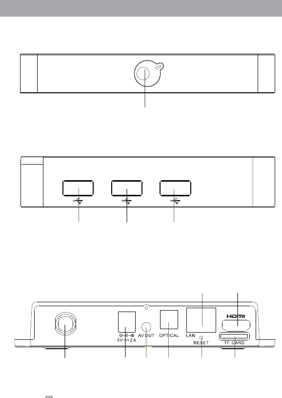
Front Panel
Rear Panel
1. Power indicator
1
;9(;9(;9(
123456
8
7
12 3
1. WiFi antenna
2. 5V 2A
3. A/V out
4. Optical fiber out
5. Reset key
6. TF card
7. RJ45 network interface
8. HDMI out
!
3
3 Rear Panel Connection
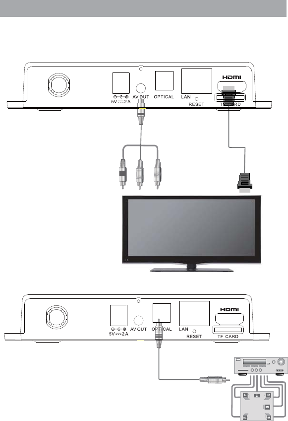
Rear Panel Connection
.*3/IUTTKIZOUTIGHRK
'<IUTTKIZOUTIGHRK
Optical fiber connection cable
White Red Yellow
!
4
3 Rear Panel Connection
Rear Panel Connection
Tips:
Some applications require mouse operation!
Tips:
Certain functions may be added or deleted due to software
update. The unit shall prevail.
Internet
Broadband Internet connection
Broadband Router/Modem
Wired Network
WAN 1 2 LAN 3 4
5
4 Remote
1
2
3
4
6
7
8
5
10
14
15
9
11
13
12
17
18
19
21
24
20
22
23
25 26
16 27
6
4 Remote
1
2
3
4
5
6
7
8
9
10
11
12
13
14
15
16
17
18
21
22
23
24
25
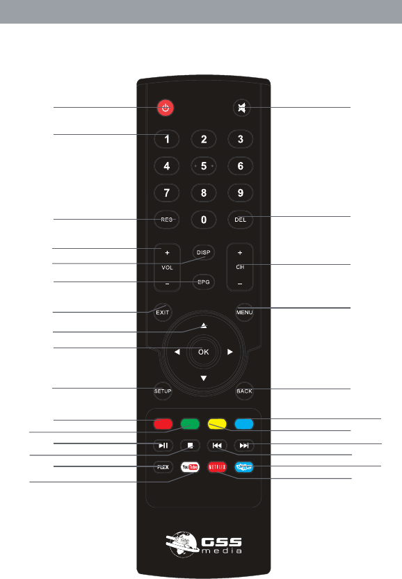
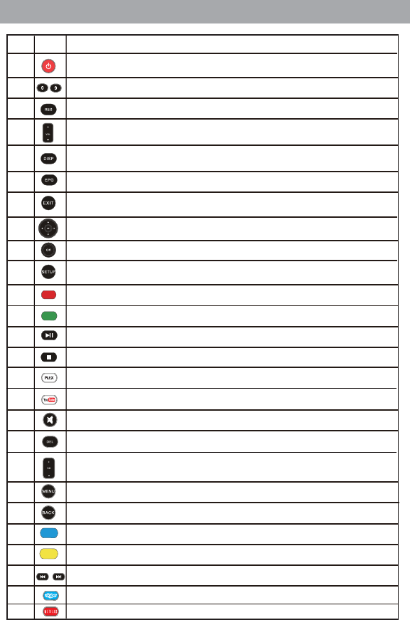
Shortcut to the Main Menu
Go in and out of Standby
Volume Up/Dn
Shortcut to the System Setup menu
Mute/Un-Mute sound
Skip to next file/Skip to previous file
Red button. Functionality depends on the application
19
20
No.
Key Function
Numeric input
Generic exit button. Functionality depends on the application
Move left, right, up, down
OK
Green button. Functionality depends on the application
Play/Pause
Stop
Blue button. Functionality depends on the application
Yellow button. Functionality depends on the application
26
Change the screen resolution on the fly
Show additional information when available
Show EPG when available
Shortcut to the PLEX APP
Shortcut to the YouTube APP
Multipurpose delete button
Channel Up/Dn
Back one level
Shortcut to the Skype APP
Shortcut to the Netflix APP
5 First Time Set-Up
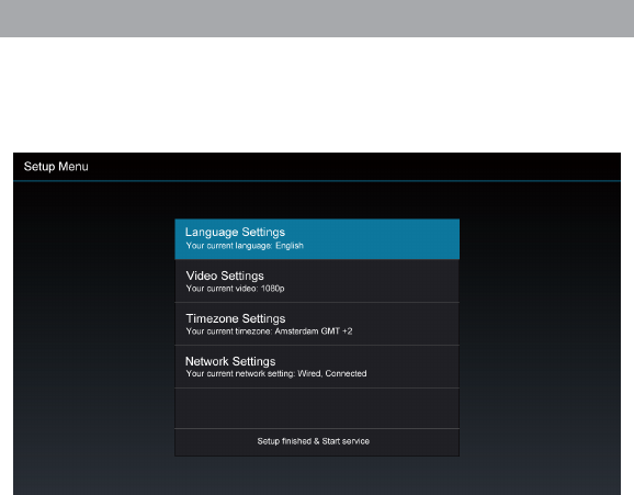
When operating the box for the first time, you will be asked to set-up a basic set of features that
are essential for having a good IPTV experience. Be advised that without a proper internet
connection you cannot proceed to the main menu. Chapter 6 describes in detail on how to set-up
the network.
7
6 Network Settings
6.1 Available Networks and Checking Current Network Status
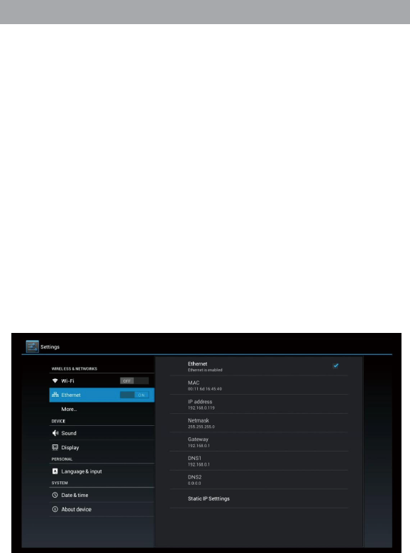
Check the available guaranteed bandwidth with your ISP.
Recommended bandwidth: To ensure smooth playing of Internet video resources, the bandwidth
should be at least 2Mbps.
Router: For easy and quick connection, a wireless router is recommended. A common wireless
router can meet the bandwidth requirement for ITPV. The THD601DC Set-Top-Box integrates
a Wi-Fi module, which can connect to wireless router directly.
When you intend to stream high quality movies from internal network, an Ethernet cable connection
is recommended.
6.2 Connecting to Cable Network
6.2.1 Connecting to the router
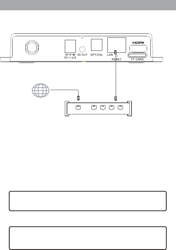
1. Connect the network cable to the LAN port of this unit, and connect the other end to the LAN
port of the router.
2. Turn on the unit, select Settings – Cable Network, check the option “Cable Network” or press
OK on the remote control to set this option to “ON”.
3. After turning on the cable network, check if the “Cable Network” is selected; if DHCP (Dynamic
Host Configuration Protocol) is enabled in the router, this unit will obtain IP address automatically.
4. After connecting to the network, the “Cable Network” option shows: Cable network is turned on;
IP address, gateway, subnet mask and other information are listed below.
8
6.3 Connecting to Wi-Fi
6.3.1 Connecting to wireless router
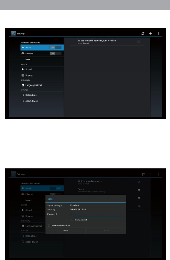
1. Enter “Settings” in the home screen, select “Wi-Fi” in the left, which has a switch in the right;
please turn the switch to “ON” or press OK on the remote control to set this option to “ON”.
6 Network Settings
3. In the picture below, two Wi-Fi sources are available. The text below the name (SSID) indicates
the encryption mode of the Wi-Fi connection. The icon to the right indicates the signal strength .
The small lock indicates that the connection is encrypted and password is needed.
4. If the wireless network isn’t encrypted, you can connect to it directly.
5. If the network is encrypted, select the Wi-Fi name to pop up the window for password, press OK
on the remote control and call out the soft keypad on the screen, enter the password, select
“Next” on the keypad or press the Return key on the remote control to hide the keypad, and then
select “Connect” to connect to it. (Note: to hide the keypad on the TV box, press the Return key
on the remote control.)
9
below:
2. When Wi-Fi is turned on, the right will show the available Wi-Fi connections (if any), as shown
7 Video Settings
10
7.1 Available Video Interfaces
1. Connecting to TV through HDMI cable
If the TV set has HDMI interface, the unit can be connected to the TV set with HDMI cable. After
connecting, turn on the unit. the LED on the front panel is turned on, the screen shows boot
logos and then enters the home screen after several seconds.
2. Connecting to TV through TV cable
Connect the AV cable to the AV OUT port, connect the yellow video input plug of the TV
set to the yellow CVBS video interface, and connect the white and red plug to the left and right
audio interfaces respectively. Turn on the TV, switch to AV input mode, turn on the unit, the LED
on the front panel is turned on, the screen shows boot logos and then enters the home screen
after several seconds.
Note: Not all models come with the special AV cable. Ask your supplier for details.
7.2 Video Output Settings
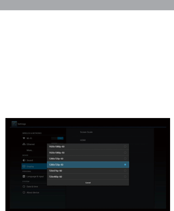
7.2.1 Resolution settings
Before operating for the first time, please adjust the screen resolution to achieve the optimal display:
In Settings, enter Display - Output Resolution:
This option is mainly intended for HDMI interface output.
If AV port output is used, enter Display - AV Output to set.
Note: When the selected resolution is not supported by TV-Set, the system will automatically return
to the latest good resolution. As an extra safety net, the “RES” button on the remote control can be
used at all times to change the resolution without having visual contact with the setting menu.
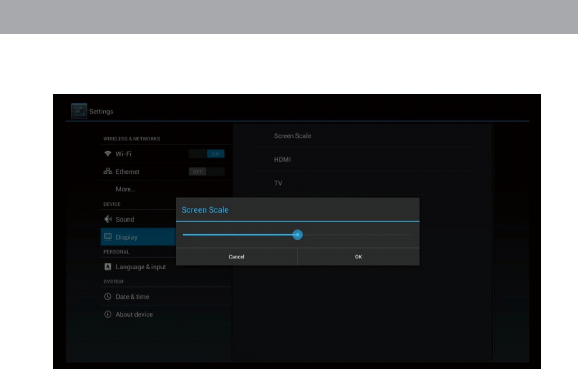
7.2.2 Screen size settings
After adjusting the resolution, the screen edges will be cut or have black borders. Enter Settings -
Display - Aspect Ratio, and press the Left/Right key on the remote control in the aspect ratio
window and adjust.
Tips: Zoom out the screen to the smallest (adjust the slider to the left), and then zoom in the
7 Video Settings
11
screen (adjust the slider to the right), check the screen edges, and it is optimal when the screen
edges coincide with the TV edges.

!
12
Interfaces
AV output
USB LAN
HDMI TF expansion slot
Power supply
Dimensions
Weight
Optical fiber Wi-Fi
5V/2A
150x110x33mm
0.2kg
8. Specifications
FCC STATEMENT
1. This device complies with Part 15 of the FCC Rules. Operation is subject to the
following two conditions:
(1) This device may not cause harmful interference.
(2) This device must accept any interference received, including interference that may
cause undesired operation.
Any changes or modifications not expressly approved by the party responsible
for compliance could void the user's authority to operate this equipment.
NOTE: This equipment has been tested and found to comply with the limits for a Class B
digital device, pursuant to Part 15 of the FCC Rules. These limits are designed to provide
reasonable protection against harmful interference in a residential installation.
This equipment generates uses and can radiate radio frequency energy and, if not
installed and used in accordance with the instructions, may cause harmful interference to
radio communications. However, there is no guarantee that interference will not occur in a
particular installation. If this equipment does cause harmful interference to radio or
television reception, which can be determined by turning the equipment off and on, the
user is encouraged to try to correct the interference by one or more of the following
measures:
Reorient or relocate the receiving antenna.
Increase the separation between the equipment and receiver.
Connect the equipment into an outlet on a circuit different from that to which the
receiver is connected.
Consult the dealer or an e xperienced radio/TV technician for help.
FCC Radiation Exposure Statement
The antennas used for this transmitter must be installed to provide a separation distance of at least 20 cm from all persons and must not be
co-located for operating in conjunction with any other antenna or transmitter.