Teles Informationstechnologien CDMA32VOIPUS Cellular/PCS CDMA Gateway User Manual TELES iGATE V16 2
Teles AG Informationstechnologien Cellular/PCS CDMA Gateway TELES iGATE V16 2
Users Manual

CELLX
Reference Manual
Software version 16.2

TELES AG | HEADQUARTERS
Ernst-Reuter-Platz 8
10587 Berlin
GERMANY
Phone +49 30 399 28-066
Fax +49 30 399 28-051
E-mail sales@teles.com
http www.teles.com
© Copyright 2010 TELES AG Informationstechnologien. All rights reserved.
TELES®, IntraSTAR®, Intra*®, iGATE®, and iSWITCH® are registered trademarks of TELES AG
Informationstechnologien. All other trademarks used are the property of their respective owners.
The supplied hardware/software systems are protected by copyright and can be used solely by their lawful
owners.
All text and figures in this publication have been compiled with great attention to detail. Nonetheless,
inaccuracies and typographical errors cannot be entirely avoided. TELES AG Informationstechnologien
provides this document 'as is' without warranty of any kind, expressed or implied. TELES AG
Informationstechnologien reserves the right to make changes in product design or specifications without
notice.
Reference Manual
CELLX
CELLX 16.2
Revised:18 November 2011Software version: 16.2

Page 1CELLX 16.2
1 About this manual . . . . . . . . . . . . . . . . . . . . . . . . . . . . . . . . . . . 6
1.1 Organization . . . . . . . . . . . . . . . . . . . . . . . . . . . . . . . . . . . . . . . . . . . . . . . . . . . . . . . . . .7
1.2 Conventions. . . . . . . . . . . . . . . . . . . . . . . . . . . . . . . . . . . . . . . . . . . . . . . . . . . . . . . . . . .7
1.3 Safety symbols . . . . . . . . . . . . . . . . . . . . . . . . . . . . . . . . . . . . . . . . . . . . . . . . . . . . . . . .8
2 Safety and security precautions . . . . . . . . . . . . . . . . . . . . . . . . 9
2.1 Safety measures . . . . . . . . . . . . . . . . . . . . . . . . . . . . . . . . . . . . . . . . . . . . . . . . . . . . . .10
2.2 FCC / Industry Canada Notice . . . . . . . . . . . . . . . . . . . . . . . . . . . . . . . . . . . . . . . . . . .10
2.3 EMC protection . . . . . . . . . . . . . . . . . . . . . . . . . . . . . . . . . . . . . . . . . . . . . . . . . . . . . . .11
2.4 System security . . . . . . . . . . . . . . . . . . . . . . . . . . . . . . . . . . . . . . . . . . . . . . . . . . . . . . .11
2.5 Servicing the system . . . . . . . . . . . . . . . . . . . . . . . . . . . . . . . . . . . . . . . . . . . . . . . . . . .11
2.5.1 Replacing components . . . . . . . . . . . . . . . . . . . . . . . . . . . . . . . . . . . . . . . . . . . . . . . . .12
2.5.2 Protecting the operating system . . . . . . . . . . . . . . . . . . . . . . . . . . . . . . . . . . . . . . . . .12
2.6 CDR files. . . . . . . . . . . . . . . . . . . . . . . . . . . . . . . . . . . . . . . . . . . . . . . . . . . . . . . . . . . . .13
2.7 Network security. . . . . . . . . . . . . . . . . . . . . . . . . . . . . . . . . . . . . . . . . . . . . . . . . . . . . .13
3 Overview. . . . . . . . . . . . . . . . . . . . . . . . . . . . . . . . . . . . . . . . . . 15
3.1 What’s new in version 16.2 . . . . . . . . . . . . . . . . . . . . . . . . . . . . . . . . . . . . . . . . . . . . .16
3.2 New Access Gateway product names starting version 16.1 . . . . . . . . . . . . . . . . . . .16
3.3 How CELLX works . . . . . . . . . . . . . . . . . . . . . . . . . . . . . . . . . . . . . . . . . . . . . . . . . . . . .17
3.4 Supported implementation scenarios . . . . . . . . . . . . . . . . . . . . . . . . . . . . . . . . . . . . .17
4 Installation . . . . . . . . . . . . . . . . . . . . . . . . . . . . . . . . . . . . . . . . 19
4.1 Checklist. . . . . . . . . . . . . . . . . . . . . . . . . . . . . . . . . . . . . . . . . . . . . . . . . . . . . . . . . . . . .20
4.2 Package contents. . . . . . . . . . . . . . . . . . . . . . . . . . . . . . . . . . . . . . . . . . . . . . . . . . . . . .20
4.3 Hardware description . . . . . . . . . . . . . . . . . . . . . . . . . . . . . . . . . . . . . . . . . . . . . . . . . .20
4.4 Installation requirements . . . . . . . . . . . . . . . . . . . . . . . . . . . . . . . . . . . . . . . . . . . . . . .21
4.4.1 Ethernet wiring . . . . . . . . . . . . . . . . . . . . . . . . . . . . . . . . . . . . . . . . . . . . . . . . . . . . . . .21
4.4.2 PRI wiring. . . . . . . . . . . . . . . . . . . . . . . . . . . . . . . . . . . . . . . . . . . . . . . . . . . . . . . . . . . .22
4.4.2.1 TELES to TBR12 . . . . . . . . . . . . . . . . . . . . . . . . . . . . . . . . . . . . . . . . . . . . . . . . . . . . . . .22
4.4.3 Antenna connection . . . . . . . . . . . . . . . . . . . . . . . . . . . . . . . . . . . . . . . . . . . . . . . . . . .22
4.4.4 SIM card assignment . . . . . . . . . . . . . . . . . . . . . . . . . . . . . . . . . . . . . . . . . . . . . . . . . . .22
4.5 Preparing for installation . . . . . . . . . . . . . . . . . . . . . . . . . . . . . . . . . . . . . . . . . . . . . . .25
4.6 Hardware connection . . . . . . . . . . . . . . . . . . . . . . . . . . . . . . . . . . . . . . . . . . . . . . . . . .25
4.7 Startup with Quickstart . . . . . . . . . . . . . . . . . . . . . . . . . . . . . . . . . . . . . . . . . . . . . . . .25
4.7.1 Installing Quickstart . . . . . . . . . . . . . . . . . . . . . . . . . . . . . . . . . . . . . . . . . . . . . . . . . . .25
4.7.2 Configuration with Quickstart . . . . . . . . . . . . . . . . . . . . . . . . . . . . . . . . . . . . . . . . . . .26
4.8 Startup via GUI . . . . . . . . . . . . . . . . . . . . . . . . . . . . . . . . . . . . . . . . . . . . . . . . . . . . . . .28
4.9 LED functionality. . . . . . . . . . . . . . . . . . . . . . . . . . . . . . . . . . . . . . . . . . . . . . . . . . . . . .29
4.9.1 Ethernet port LEDs . . . . . . . . . . . . . . . . . . . . . . . . . . . . . . . . . . . . . . . . . . . . . . . . . . . .29
4.9.2 Base Board PRI port LEDs . . . . . . . . . . . . . . . . . . . . . . . . . . . . . . . . . . . . . . . . . . . . . . .29
4.9.3 Mobile Board SIM card LEDs. . . . . . . . . . . . . . . . . . . . . . . . . . . . . . . . . . . . . . . . . . . . .29
4.10 Remote access and access security. . . . . . . . . . . . . . . . . . . . . . . . . . . . . . . . . . . . . . . .31
4.10.1 GATE Manager. . . . . . . . . . . . . . . . . . . . . . . . . . . . . . . . . . . . . . . . . . . . . . . . . . . . . . . .31
4.10.2 Graphical user interface (GUI) . . . . . . . . . . . . . . . . . . . . . . . . . . . . . . . . . . . . . . . . . . .32
4.10.3 FTP . . . . . . . . . . . . . . . . . . . . . . . . . . . . . . . . . . . . . . . . . . . . . . . . . . . . . . . . . . . . . . . . .33
4.10.4 Setting a password for remote access . . . . . . . . . . . . . . . . . . . . . . . . . . . . . . . . . . . . .34

Page 2CELLX 16.2
5 Configuration files . . . . . . . . . . . . . . . . . . . . . . . . . . . . . . . . . . 36
5.1 Configuration file ip.cfg . . . . . . . . . . . . . . . . . . . . . . . . . . . . . . . . . . . . . . . . . . . . . . . .38
5.1.1 System section configuration . . . . . . . . . . . . . . . . . . . . . . . . . . . . . . . . . . . . . . . . . . . .38
5.1.2 Ethernet interface configuration . . . . . . . . . . . . . . . . . . . . . . . . . . . . . . . . . . . . . . . . .39
5.1.3 GUI settings . . . . . . . . . . . . . . . . . . . . . . . . . . . . . . . . . . . . . . . . . . . . . . . . . . . . . . . . . .39
5.1.4 Bridge configuration. . . . . . . . . . . . . . . . . . . . . . . . . . . . . . . . . . . . . . . . . . . . . . . . . . .40
5.1.5 NAT configuration. . . . . . . . . . . . . . . . . . . . . . . . . . . . . . . . . . . . . . . . . . . . . . . . . . . . .40
5.1.6 PPPoE configuration . . . . . . . . . . . . . . . . . . . . . . . . . . . . . . . . . . . . . . . . . . . . . . . . . . .41
5.1.7 Firewall settings. . . . . . . . . . . . . . . . . . . . . . . . . . . . . . . . . . . . . . . . . . . . . . . . . . . . . . .42
5.1.8 Bandwidth control. . . . . . . . . . . . . . . . . . . . . . . . . . . . . . . . . . . . . . . . . . . . . . . . . . . . .44
5.1.9 DHCP server settings . . . . . . . . . . . . . . . . . . . . . . . . . . . . . . . . . . . . . . . . . . . . . . . . . . .46
5.1.10 DNSmasq settings . . . . . . . . . . . . . . . . . . . . . . . . . . . . . . . . . . . . . . . . . . . . . . . . . . . . .47
5.1.11 PPP configuration for mobile and ISDN dial-up . . . . . . . . . . . . . . . . . . . . . . . . . . . . .48
5.1.12 VLAN configuration. . . . . . . . . . . . . . . . . . . . . . . . . . . . . . . . . . . . . . . . . . . . . . . . . . . .49
5.1.13 Examples . . . . . . . . . . . . . . . . . . . . . . . . . . . . . . . . . . . . . . . . . . . . . . . . . . . . . . . . . . . .50
5.1.13.1 Default configuration . . . . . . . . . . . . . . . . . . . . . . . . . . . . . . . . . . . . . . . . . . . . . . . . . .50
5.1.13.2 Active ethernet bridge . . . . . . . . . . . . . . . . . . . . . . . . . . . . . . . . . . . . . . . . . . . . . . . . .50
5.1.13.3 Integrated DSL-router scenario for VoIP . . . . . . . . . . . . . . . . . . . . . . . . . . . . . . . . . . .51
5.1.13.4 VLAN scenario . . . . . . . . . . . . . . . . . . . . . . . . . . . . . . . . . . . . . . . . . . . . . . . . . . . . . . . .52
5.2 Configuration file pabx.cfg . . . . . . . . . . . . . . . . . . . . . . . . . . . . . . . . . . . . . . . . . . . . .52
5.2.1 System settings . . . . . . . . . . . . . . . . . . . . . . . . . . . . . . . . . . . . . . . . . . . . . . . . . . . . . . .52
5.2.1.1 Global Settings. . . . . . . . . . . . . . . . . . . . . . . . . . . . . . . . . . . . . . . . . . . . . . . . . . . . . . . .52
5.2.1.2 Log files . . . . . . . . . . . . . . . . . . . . . . . . . . . . . . . . . . . . . . . . . . . . . . . . . . . . . . . . . . . . .53
5.2.1.3 Night configuration. . . . . . . . . . . . . . . . . . . . . . . . . . . . . . . . . . . . . . . . . . . . . . . . . . . .55
5.2.1.4 Controllers . . . . . . . . . . . . . . . . . . . . . . . . . . . . . . . . . . . . . . . . . . . . . . . . . . . . . . . . . . .56
5.2.1.5 Subscribers . . . . . . . . . . . . . . . . . . . . . . . . . . . . . . . . . . . . . . . . . . . . . . . . . . . . . . . . . . .59
5.2.1.6 Global settings. . . . . . . . . . . . . . . . . . . . . . . . . . . . . . . . . . . . . . . . . . . . . . . . . . . . . . . .62
5.2.2 SMTP-client configuration . . . . . . . . . . . . . . . . . . . . . . . . . . . . . . . . . . . . . . . . . . . . . .65
5.2.3 Number portability settings . . . . . . . . . . . . . . . . . . . . . . . . . . . . . . . . . . . . . . . . . . . . .67
5.2.4 SNMP settings . . . . . . . . . . . . . . . . . . . . . . . . . . . . . . . . . . . . . . . . . . . . . . . . . . . . . . . .68
5.2.5 Time-controlled configuration settings . . . . . . . . . . . . . . . . . . . . . . . . . . . . . . . . . . . .68
5.2.6 .CASR2 settings . . . . . . . . . . . . . . . . . . . . . . . . . . . . . . . . . . . . . . . . . . . . . . . . . . . . . . .68
5.3 Configuration file route.cfg . . . . . . . . . . . . . . . . . . . . . . . . . . . . . . . . . . . . . . . . . . . . .70
5.3.1 Entries in the [System] section . . . . . . . . . . . . . . . . . . . . . . . . . . . . . . . . . . . . . . . . . . .70
5.3.1.1 Restrict . . . . . . . . . . . . . . . . . . . . . . . . . . . . . . . . . . . . . . . . . . . . . . . . . . . . . . . . . . . . . .70
5.3.1.2 MapAll . . . . . . . . . . . . . . . . . . . . . . . . . . . . . . . . . . . . . . . . . . . . . . . . . . . . . . . . . . . . . .72
5.3.1.3 Redirect . . . . . . . . . . . . . . . . . . . . . . . . . . . . . . . . . . . . . . . . . . . . . . . . . . . . . . . . . . . . .74
5.3.1.4 Setting the time-controlled sections . . . . . . . . . . . . . . . . . . . . . . . . . . . . . . . . . . . . . .75
5.3.2 VoIP profiles. . . . . . . . . . . . . . . . . . . . . . . . . . . . . . . . . . . . . . . . . . . . . . . . . . . . . . . . . .76
5.3.3 Gatekeeper profiles. . . . . . . . . . . . . . . . . . . . . . . . . . . . . . . . . . . . . . . . . . . . . . . . . . . .79
5.3.4 Registrar profiles . . . . . . . . . . . . . . . . . . . . . . . . . . . . . . . . . . . . . . . . . . . . . . . . . . . . . .80
5.3.5 Radius profiles . . . . . . . . . . . . . . . . . . . . . . . . . . . . . . . . . . . . . . . . . . . . . . . . . . . . . . . .81
6 Routing examples. . . . . . . . . . . . . . . . . . . . . . . . . . . . . . . . . . . 83
6.1 CELLX integration in an H.323 carrier network. . . . . . . . . . . . . . . . . . . . . . . . . . . . . .84
6.2 CELLX as a second-generation LCR with VoIP. . . . . . . . . . . . . . . . . . . . . . . . . . . . . . .85
7 Mobile configuration options . . . . . . . . . . . . . . . . . . . . . . . . . 87
7.1 Network-specific mobile routing . . . . . . . . . . . . . . . . . . . . . . . . . . . . . . . . . . . . . . . . .88
7.1.1 Routing decisions for calls to the mobile network . . . . . . . . . . . . . . . . . . . . . . . . . . .88

Page 3CELLX 16.2
7.1.2 Using the LAIN as the mobile port address . . . . . . . . . . . . . . . . . . . . . . . . . . . . . . . . .89
7.1.3 Fixed LAIN for a mobile port . . . . . . . . . . . . . . . . . . . . . . . . . . . . . . . . . . . . . . . . . . . .90
7.2 Incoming voice calls from mobile. . . . . . . . . . . . . . . . . . . . . . . . . . . . . . . . . . . . . . . . .90
7.3 Blocking ports . . . . . . . . . . . . . . . . . . . . . . . . . . . . . . . . . . . . . . . . . . . . . . . . . . . . . . . .90
7.4 Mobile user PBX callback . . . . . . . . . . . . . . . . . . . . . . . . . . . . . . . . . . . . . . . . . . . . . . .91
7.5 Optional mobile quality parameters . . . . . . . . . . . . . . . . . . . . . . . . . . . . . . . . . . . . . .92
7.6 Deactivating mobile rerouting . . . . . . . . . . . . . . . . . . . . . . . . . . . . . . . . . . . . . . . . . . .95
7.7 Setting autodial. . . . . . . . . . . . . . . . . . . . . . . . . . . . . . . . . . . . . . . . . . . . . . . . . . . . . . .96
7.8 Disconnecting calls after ring. . . . . . . . . . . . . . . . . . . . . . . . . . . . . . . . . . . . . . . . . . . .96
7.9 Checking ports/mobile channels . . . . . . . . . . . . . . . . . . . . . . . . . . . . . . . . . . . . . . . . .96
7.10 Defining special characters for voice calls. . . . . . . . . . . . . . . . . . . . . . . . . . . . . . . . . .97
8 Signaling and routing features . . . . . . . . . . . . . . . . . . . . . . . . 98
8.1 Least cost routing . . . . . . . . . . . . . . . . . . . . . . . . . . . . . . . . . . . . . . . . . . . . . . . . . . . . .99
8.1.1 Carrier selection. . . . . . . . . . . . . . . . . . . . . . . . . . . . . . . . . . . . . . . . . . . . . . . . . . . . . . .99
8.1.1.1 Routing entries . . . . . . . . . . . . . . . . . . . . . . . . . . . . . . . . . . . . . . . . . . . . . . . . . . . . . . .99
8.1.2 Alternative routing settings . . . . . . . . . . . . . . . . . . . . . . . . . . . . . . . . . . . . . . . . . . . .100
8.1.3 Charge models. . . . . . . . . . . . . . . . . . . . . . . . . . . . . . . . . . . . . . . . . . . . . . . . . . . . . . .101
8.2 Online traffic monitor. . . . . . . . . . . . . . . . . . . . . . . . . . . . . . . . . . . . . . . . . . . . . . . . .102
8.2.1 ASR calculation and resetting statistic values and counters. . . . . . . . . . . . . . . . . . .102
8.2.1.1 Saving and sending statistics . . . . . . . . . . . . . . . . . . . . . . . . . . . . . . . . . . . . . . . . . . .103
8.2.1.2 Saving statistics . . . . . . . . . . . . . . . . . . . . . . . . . . . . . . . . . . . . . . . . . . . . . . . . . . . . . .104
8.2.1.3 Resetting statistic counters . . . . . . . . . . . . . . . . . . . . . . . . . . . . . . . . . . . . . . . . . . . . .104
8.2.2 Generating and retrieving CDRs. . . . . . . . . . . . . . . . . . . . . . . . . . . . . . . . . . . . . . . . .105
8.2.2.1 Call log . . . . . . . . . . . . . . . . . . . . . . . . . . . . . . . . . . . . . . . . . . . . . . . . . . . . . . . . . . . . .106
8.2.2.2 Missed calls list. . . . . . . . . . . . . . . . . . . . . . . . . . . . . . . . . . . . . . . . . . . . . . . . . . . . . . .111
8.2.2.3 Sending CDRs via e-mail . . . . . . . . . . . . . . . . . . . . . . . . . . . . . . . . . . . . . . . . . . . . . . .112
8.3 Ported number screening . . . . . . . . . . . . . . . . . . . . . . . . . . . . . . . . . . . . . . . . . . . . . .113
8.4 Digit collection (enblock/overlap receiving) . . . . . . . . . . . . . . . . . . . . . . . . . . . . . . .114
8.5 Rejecting data calls and specified numbers . . . . . . . . . . . . . . . . . . . . . . . . . . . . . . .115
8.5.1 Blacklist routing. . . . . . . . . . . . . . . . . . . . . . . . . . . . . . . . . . . . . . . . . . . . . . . . . . . . . .115
8.5.2 Whitelist routing . . . . . . . . . . . . . . . . . . . . . . . . . . . . . . . . . . . . . . . . . . . . . . . . . . . . .115
8.5.3 Rejecting calls with ISDN bearer capability data. . . . . . . . . . . . . . . . . . . . . . . . . . . .116
8.5.4 Specific routing of data calls via VoIP . . . . . . . . . . . . . . . . . . . . . . . . . . . . . . . . . . . .117
8.6 CLIP and CLIR . . . . . . . . . . . . . . . . . . . . . . . . . . . . . . . . . . . . . . . . . . . . . . . . . . . . . . . .117
8.6.1 Routing CLIP and CLIR calls. . . . . . . . . . . . . . . . . . . . . . . . . . . . . . . . . . . . . . . . . . . . .117
8.6.2 Routing calls without CLIR . . . . . . . . . . . . . . . . . . . . . . . . . . . . . . . . . . . . . . . . . . . . .118
8.6.2.1 Setting CLIR . . . . . . . . . . . . . . . . . . . . . . . . . . . . . . . . . . . . . . . . . . . . . . . . . . . . . . . . .118
8.6.2.2 Setting CLIP . . . . . . . . . . . . . . . . . . . . . . . . . . . . . . . . . . . . . . . . . . . . . . . . . . . . . . . . .119
8.7 Conversion of call numbers . . . . . . . . . . . . . . . . . . . . . . . . . . . . . . . . . . . . . . . . . . . .119
8.8 Overwriting OAD . . . . . . . . . . . . . . . . . . . . . . . . . . . . . . . . . . . . . . . . . . . . . . . . . . . .119
8.9 Setting number type in OAD/DAD. . . . . . . . . . . . . . . . . . . . . . . . . . . . . . . . . . . . . . .120
8.10 Setting the screening indicator . . . . . . . . . . . . . . . . . . . . . . . . . . . . . . . . . . . . . . . . .122
8.11 Setting a default OAD. . . . . . . . . . . . . . . . . . . . . . . . . . . . . . . . . . . . . . . . . . . . . . . . .123
8.12 Setting or removing sending complete byte in setup . . . . . . . . . . . . . . . . . . . . . . .123
8.12.1 Exclusion from SIM minutes counter . . . . . . . . . . . . . . . . . . . . . . . . . . . . . . . . . . . . .124
8.13 Miscellaneous routing methods. . . . . . . . . . . . . . . . . . . . . . . . . . . . . . . . . . . . . . . . .124
8.13.1 Routing calls without a destination number. . . . . . . . . . . . . . . . . . . . . . . . . . . . . . .124
8.13.2 Routing calls based on extension prefix or the length of the DAD . . . . . . . . . . . . .125
8.14 Changing cause values . . . . . . . . . . . . . . . . . . . . . . . . . . . . . . . . . . . . . . . . . . . . . . . .126
8.15 Call forking . . . . . . . . . . . . . . . . . . . . . . . . . . . . . . . . . . . . . . . . . . . . . . . . . . . . . . . . .126

Page 4CELLX 16.2
9 Additional VoIP parameters. . . . . . . . . . . . . . . . . . . . . . . . . . 128
9.1 Signaling parameters . . . . . . . . . . . . . . . . . . . . . . . . . . . . . . . . . . . . . . . . . . . . . . . . .129
9.2 Registrar parameters. . . . . . . . . . . . . . . . . . . . . . . . . . . . . . . . . . . . . . . . . . . . . . . . . .136
9.3 Routing parameters . . . . . . . . . . . . . . . . . . . . . . . . . . . . . . . . . . . . . . . . . . . . . . . . . .137
9.4 Quality parameters . . . . . . . . . . . . . . . . . . . . . . . . . . . . . . . . . . . . . . . . . . . . . . . . . . .138
9.5 Compression parameters . . . . . . . . . . . . . . . . . . . . . . . . . . . . . . . . . . . . . . . . . . . . . .142
9.6 Fax/modem parameters . . . . . . . . . . . . . . . . . . . . . . . . . . . . . . . . . . . . . . . . . . . . . . .143
9.7 DTMF parameters . . . . . . . . . . . . . . . . . . . . . . . . . . . . . . . . . . . . . . . . . . . . . . . . . . . .144
10 System maintenance and software update . . . . . . . . . . . . . 145
10.1 Configuration errors . . . . . . . . . . . . . . . . . . . . . . . . . . . . . . . . . . . . . . . . . . . . . . . . . .146
10.2 Status and error messages . . . . . . . . . . . . . . . . . . . . . . . . . . . . . . . . . . . . . . . . . . . . .146
10.3 Software update . . . . . . . . . . . . . . . . . . . . . . . . . . . . . . . . . . . . . . . . . . . . . . . . . . . . .151
10.4 SNMP agent . . . . . . . . . . . . . . . . . . . . . . . . . . . . . . . . . . . . . . . . . . . . . . . . . . . . . . . . .152
10.5 DNS forwarder. . . . . . . . . . . . . . . . . . . . . . . . . . . . . . . . . . . . . . . . . . . . . . . . . . . . . . .155
10.6 ipupdate - DynDNS client . . . . . . . . . . . . . . . . . . . . . . . . . . . . . . . . . . . . . . . . . . . . . .156
10.7 Trace . . . . . . . . . . . . . . . . . . . . . . . . . . . . . . . . . . . . . . . . . . . . . . . . . . . . . . . . . . . . . . .157
10.7.1 ISDN trace output . . . . . . . . . . . . . . . . . . . . . . . . . . . . . . . . . . . . . . . . . . . . . . . . . . . .160
10.7.2 GSM/CDMA/UMTS trace output . . . . . . . . . . . . . . . . . . . . . . . . . . . . . . . . . . . . . . . . .161
10.7.3 VoIP trace output . . . . . . . . . . . . . . . . . . . . . . . . . . . . . . . . . . . . . . . . . . . . . . . . . . . .162
10.7.3.1 Interface IP network . . . . . . . . . . . . . . . . . . . . . . . . . . . . . . . . . . . . . . . . . . . . . . . . . .163
10.7.3.2 Internal protocol interface (to ISDN, mobile) . . . . . . . . . . . . . . . . . . . . . . . . . . . . . .171
10.7.3.3 H.245 messages . . . . . . . . . . . . . . . . . . . . . . . . . . . . . . . . . . . . . . . . . . . . . . . . . . . . . .173
10.7.3.4 RAS (registration, admission, status) . . . . . . . . . . . . . . . . . . . . . . . . . . . . . . . . . . . . .177
10.7.3.5 ENUM output. . . . . . . . . . . . . . . . . . . . . . . . . . . . . . . . . . . . . . . . . . . . . . . . . . . . . . . .181
10.7.3.6 Examples . . . . . . . . . . . . . . . . . . . . . . . . . . . . . . . . . . . . . . . . . . . . . . . . . . . . . . . . . . .182
10.7.4 Remote output . . . . . . . . . . . . . . . . . . . . . . . . . . . . . . . . . . . . . . . . . . . . . . . . . . . . . .185
10.7.5 SMTP trace output. . . . . . . . . . . . . . . . . . . . . . . . . . . . . . . . . . . . . . . . . . . . . . . . . . . .186
10.7.6 Number portability trace output . . . . . . . . . . . . . . . . . . . . . . . . . . . . . . . . . . . . . . . .189
10.7.7 DTMF tone trace output . . . . . . . . . . . . . . . . . . . . . . . . . . . . . . . . . . . . . . . . . . . . . . .189
11 Feature packages . . . . . . . . . . . . . . . . . . . . . . . . . . . . . . . . . . 192
11.1 Activating the license . . . . . . . . . . . . . . . . . . . . . . . . . . . . . . . . . . . . . . . . . . . . . . . . .193
11.2 Two stage dialing/callback server functionality. . . . . . . . . . . . . . . . . . . . . . . . . . . .194
11.2.1 Announcements. . . . . . . . . . . . . . . . . . . . . . . . . . . . . . . . . . . . . . . . . . . . . . . . . . . . . .195
11.2.2 Two stage dialing with DTMF. . . . . . . . . . . . . . . . . . . . . . . . . . . . . . . . . . . . . . . . . . .195
11.2.3 Callback with DTMF and OAD as callback number . . . . . . . . . . . . . . . . . . . . . . . . . .197
11.2.4 Callback with DTMF and preconfigured callback number . . . . . . . . . . . . . . . . . . . .198
11.2.5 Callback to OAD with predefined destination number . . . . . . . . . . . . . . . . . . . . . .199
11.2.6 Callback with PIN and preconfigured callback number . . . . . . . . . . . . . . . . . . . . . .199
11.3 Least cost routing . . . . . . . . . . . . . . . . . . . . . . . . . . . . . . . . . . . . . . . . . . . . . . . . . . . .200
11.3.1 Carrier selection. . . . . . . . . . . . . . . . . . . . . . . . . . . . . . . . . . . . . . . . . . . . . . . . . . . . . .201
11.3.1.1 Routing entries . . . . . . . . . . . . . . . . . . . . . . . . . . . . . . . . . . . . . . . . . . . . . . . . . . . . . .201
11.3.2 Alternative routing settings . . . . . . . . . . . . . . . . . . . . . . . . . . . . . . . . . . . . . . . . . . . .201
11.3.3 Charge models. . . . . . . . . . . . . . . . . . . . . . . . . . . . . . . . . . . . . . . . . . . . . . . . . . . . . . .202
11.3.4 Generating charges with the . . . . . . . . . . . . . . . . . . . . . . . . . . . . . . . . . . . . . . . . . . .203
11.4 Online traffic monitor. . . . . . . . . . . . . . . . . . . . . . . . . . . . . . . . . . . . . . . . . . . . . . . . .206

Page 5CELLX 16.2
11.4.1 Generating and retrieving CDRs. . . . . . . . . . . . . . . . . . . . . . . . . . . . . . . . . . . . . . . . .206
11.4.1.1 Call log . . . . . . . . . . . . . . . . . . . . . . . . . . . . . . . . . . . . . . . . . . . . . . . . . . . . . . . . . . . . .207
11.4.1.2 Missed calls list. . . . . . . . . . . . . . . . . . . . . . . . . . . . . . . . . . . . . . . . . . . . . . . . . . . . . . .211
11.4.1.3 Sending CDRs via e-mail . . . . . . . . . . . . . . . . . . . . . . . . . . . . . . . . . . . . . . . . . . . . . . .213
11.5 Ported number screening . . . . . . . . . . . . . . . . . . . . . . . . . . . . . . . . . . . . . . . . . . . . . .213
11.6 Call recording. . . . . . . . . . . . . . . . . . . . . . . . . . . . . . . . . . . . . . . . . . . . . . . . . . . . . . . .215
11.6.1 Call recording procedure . . . . . . . . . . . . . . . . . . . . . . . . . . . . . . . . . . . . . . . . . . . . . .216
11.6.2 Call recording configuration. . . . . . . . . . . . . . . . . . . . . . . . . . . . . . . . . . . . . . . . . . . .216
12 Troubleshooting . . . . . . . . . . . . . . . . . . . . . . . . . . . . . . . . . . . 220
12.1 No connection to the system . . . . . . . . . . . . . . . . . . . . . . . . . . . . . . . . . . . . . . . . . . .221
12.1.1 System does not start correctly. . . . . . . . . . . . . . . . . . . . . . . . . . . . . . . . . . . . . . . . . .221
12.1.2 Web interface is not accessible. . . . . . . . . . . . . . . . . . . . . . . . . . . . . . . . . . . . . . . . . .222
12.1.3 IP address settings . . . . . . . . . . . . . . . . . . . . . . . . . . . . . . . . . . . . . . . . . . . . . . . . . . . .223
12.1.4 Firewall issues and NAT / PAT settings . . . . . . . . . . . . . . . . . . . . . . . . . . . . . . . . . . . .223
12.1.5 ISDN access: dial-in number missing or wrong . . . . . . . . . . . . . . . . . . . . . . . . . . . . .223
12.1.6 ISDN port not loaded correctly / not active . . . . . . . . . . . . . . . . . . . . . . . . . . . . . . . .224
12.2 No calls are possible . . . . . . . . . . . . . . . . . . . . . . . . . . . . . . . . . . . . . . . . . . . . . . . . . .225
12.2.1 Call does not arrive on the gateway . . . . . . . . . . . . . . . . . . . . . . . . . . . . . . . . . . . . .225
12.2.2 Call is rejected or not routed to the right destination address . . . . . . . . . . . . . . . .228
12.2.3 Call is rejected elsewhere . . . . . . . . . . . . . . . . . . . . . . . . . . . . . . . . . . . . . . . . . . . . . .231
12.3 Software update problems. . . . . . . . . . . . . . . . . . . . . . . . . . . . . . . . . . . . . . . . . . . . .231

1 About this manual

1 About this manual
Page 7CELLX 16.2
Congratulations on the purchase of your new CELLX! This manual is set up to guide you
through the step-by-step installation of your CELLX, so that you can follow it through from
the front to the back. Quick-installation instructions appear in Chapter 4.7 Startup with
Quickstart on page 25.
Make sure you familiarize yourself thoroughly with the safety and security precautions de-
tailed in Chapter 2 Safety and security precautions before you begin to install your CELLX.
TELES is not liable for any damage or injury resulting from a failure to follow these safety and
security instructions!
1.1 Organization
This manual is organized into the following chapters.
Chapter 1 About this manual introduces the CELLX Systems Manual and how it is set
up.
Chapter 2 Safety and security precautions contains information about security issues
relevant to connection with the IP network.
Chapter 3 Overview briefly describes the CELLX and its implementation scenarios.
Chapter 4 Installation contains information on how to connect and configure the
system so that it is ready for operation.
Chapter 5 Configuration files describes the CELLX’s individual configuration files and
parameters.
Chapter 7 Mobile configuration options describes mobile configuration entries.
Chapter 8 Signaling and routing features describes configuration settings in the
route.cfg used for adjusting PRI signaling and customizing the configuration for
specific scenarios.
Chapter 9 Additional VoIP parameters contains additional configuration entries to fine-
tune communication with the VoIP peer.
Chapter 10 System maintenance and software update describes system messages that
are saved in the protocol file, as well as trace options.
Chapter 12 Troubleshooting contains troubleshooting suggestions.
1.2 Conventions
This document uses the following typographic conventions:
Bold – items from the GUI menu.
Halfbold – items from the GUI and the menu.
Code – file names, variables and constants in configuration files or commands in body
text.
"Conventions" on page 7 – cross-references can be accessed in the PDF files by a single
mouse click.
Configuration data or extracts are written in single-column tables with a gray background.

1 About this manual
Page 8CELLX 16.2
1.3 Safety symbols
The following symbols are used to indicate important information and to describe levels of
possible danger.
Note
Useful information with no safety implications.
Attention
Information that must be adhered to as it is necessary to ensure that the system functions cor-
rectly and to avoid material damage.
Warning
Danger. Could cause personal injury or damage to the system.
Dangerous voltage
Could cause injury by high voltage and/or damage the system.
Electrostatic discharge
Components at risk of discharge must be grounded before being touched.
i
i
!
!
!
!

2 Safety and security precautions
2 Safety and security precautions
Page 10CELLX 16.2
Please be sure and take time to read this section to ensure your personal safety and proper
operation of your TELES Infrastructure System.
To avoid personal injury or damage to the system, please follow all safety instructions before
you begin working on your TELES Infrastructure System.
TELES Infrastructure Systems are CE certified and fulfill all relevant security requirements. The
manufacturer assumes no liability for consequential damages or for damages resulting from
unauthorized changes.
This chapter applies for all Access Gateways. Information that applies only for individual
Access Gateways specifies the system for which it applies.
2.1 Safety measures
2.2 FCC / Industry Canada Notice
This equipment complies with FCC radiation exposure limits set forth for an uncontrolled en-
vironment. This equipment must be installed and operated with a minimum distance between
the antennas and persons of:
58 cm for iGATE and CELLX GSM or
20 cm for CELLX CDMA.
The minimum distance between gateway antenna and other antennas must be:
262cm for iGATE and CELLX GSM or
20 cm for CELLX CDMA.
The CELLX has been tested and found to comply with the limits for a Class B digital device,
pursuant to Part 15 of the FCC Rules. These limits are designed to provide reasonable pro-
tection against harmful interference in a residential installation. This equipment generates,
uses and can radiate radio frequency energy and, if not installed and used in accordance with
the instructions, may cause harmful interference to radio communications. However, there
is no guarantee that interference will not occur in a particular installation. If this equipment
does cause harmful interference to radio or television reception, which can be determined by
Danger of electric shock - the power supplies run on 230 V. Unplug the TELES Infrastructure
System from its power source before working on the power supply or extension socket.
Bear in mind that telephone and WAN lines are also energized and can cause electric shocks.
Do not insert foreign objects into openings in the device. Conductible objects can cause short
circuits that result in fire, electric shock or damage to the device.
Do not open the TELES Infrastructure System except to install an additional TELES.Component.
Changes in the device are not permitted.
Make sure to install the system near the power source and that the power source is easily ac-
cessible. Wire your system using only the cables included in the package contents. Use only
proper ISDN and Ethernet cables. Be sure to respect country-specific regulations, standards or
guidelines for accident prevention. Failure to follow these guidelines could result in system fail-
ure or damage.
The following information applies for CELLX gateways only. Changes or modifications not ex-
pressly approved by the party responsible for compliance could void the user's authority to op-
erate the equipment.
!
!
!
!
2 Safety and security precautions
Page 11CELLX 16.2
turning the equipment off and on, the user is encouraged to try to correct the interference
by one or more of the following measures:
Reorient or relocate the receiving antenna.
Increase the separation between the equipment and receiver.
Connect the equipment into an outlet on a circuit different from that to which the
receiver is connected.
Consult the dealer or an experienced radio/TV technician for help.
2.3 EMC protection
2.4 System security
This section describes all points crucial to the TELES Infrastructure System’s system security.
The system’s location must support normal operation of TELES Infrastructure Systems accord-
ing to EN ETS 300 386. Be sure to select the location with the following conditions in mind.
2.5 Servicing the system
Regular servicing ensures that your TELES.System runs trouble-free. Servicing also includes
looking after the room in which the system is set up. Ensure that the air-conditioning and its
filter system are regularly checked and that the premises are cleaned on a regular basis.
Use shielded cables.
Do not remove any housing components. They provide EMC protection.
Location: Make sure you install the system horizontally in a clean, dry, dust-free location. If
possible, use an air-conditioned site. The site must be free of strong electrical or magnetic
fields, which cause disrupted signals and, in extreme cases, system failure.
Temperature: The site must maintain a temperature between 32 and 113°F and provide ade-
quate ventilation. Be sure to guard against temperature fluctuations. Resulting condensation
can cause short circuiting. The humidity level may not exceed 80%.
To avoid overheating the system, make sure the site provides adequate ventilation.
Power: The site must contain a central emergency switch for the entire power source.
The site’s fuses must be calculated to provide adequate system security. The electrical facilities
must comply with applicable regulations.
The operating voltage and frequency may not exceed or fall below what is stated on the label.
Antenna: CELLX contains no provision or protective device against power surges or lightning
strikes.
The installation of the antenna must fulfill all necessary safety requirements. Employ the ser-
vices of a professional antenna installer.
!
!
!
!

2 Safety and security precautions
Page 12CELLX 16.2
2.5.1 Replacing components
If your system contains any of the following components, replace them according to the fol-
lowing table:
2.5.2 Protecting the operating system
Changing configuration data and/or SIM card positions may lead to malfunctions and/or mis-
routing, as well as possible consequential damage. Make changes at your own risk. TELES is
not liable for any possible damage resulting from or in relation to such changes. Please thor-
oughly check any changes you or a third party have made to your configuration!
To make changes in or perform tests on the database, make sure your hard disk or flash disk
contains enough storage space. Downloading the log files and deleting them from the system
on a regular basis will ensure your system’s reliability.
Be careful when deleting files that you do not delete any files necessary for system opera-
tion.To check storage space and/or delete files, use GATE Manager. For more information see
the document TELES.GATE Manager.
All files with the extension *.log can be deleted. To save files before deleting them, use the
Receive File option in GATE Manager.
The following files, if included, must not be deleted:
Table 2.1 Component life span
Component Life span
Filter pads 6 months
Power adapter 5 years
Fan 5 years
Table 2.2 Mandatory files
Mandatory files
Mandatory system files
boot.rc
crypto.vnd
crypto5.vnd
gbox.tz1
gbox5.tz1
igate.tz1
IMEIs.lst
license.key
netbsd5fs.vnd
netbsd5i
netbsd5z

2 Safety and security precautions
Page 13CELLX 16.2
2.6 CDR files
Call Detail Records are intended for analysis of the system’s activity only. They are not de-
signed to be used for billing purposes, as it may occur that the times they record are not exact.
2.7 Network security
Every day hackers develop new ways to break into systems through the Internet. While TELES
takes great care to ensure the security of its systems, any system with access through the In-
ternet is only as secure as its user makes it. Therefore, to avoid unwanted security breaches
and resulting system malfunctions, you must take the following steps to secure your TELES
system if you connect it to the Internet:
Use an application gateway or a packet firewall.
To limit access to the system to secure remote devices, delete the default route and add
individual secure network segments.
Access to the system via Telnet, FTP, GUI, or GATE Manager must be password
protected. Do not use obvious passwords (anything from sesame to your mother-in-
laws maiden name). Remember: the password that is easiest to remember is also likely
to be easiest to crack.
The firewall must be able to check the following information and only allow trusted users to
access the TELES system:
IP source address
IP destination address
Protocol (whether the packet is TCP, UDP, or ICMP)
TCP or UDP source port
TCP or UDP destination port
ICMP message type
netbsdfs.gz
netbsdi
netbsdz
start
tools.tz0
xgate.tz1
xgate.vnd
Mandatory configuration files
ip.cfg
pabx.cfg
route.cfg
Table 2.2 Mandatory files (continued)
Mandatory files

2 Safety and security precautions
Page 14CELLX 16.2
For operation and remote administration of your TELES.System, open only the following ports
only when the indicated services are used:
Table 2.3 Default ports used for specific services
Service Protocol Port
For all systems
FTP TCP 21 (default, can be set)
Telnet (for TELES debug access
only)
TCP 23 (default, can be set)
SMTP TCP 25
DNS forward UDP 53
HTTP TCP 80 (default, can be set)
SNTP UDP 123
SNMP UDP 161 (default, can be set)
H.225 registration, admission,
status
UDP 1719 (default, can be set)
H.225 signaling TCP 1720 (default, can be set)
Radius UDP 1812 (default, can be set)
Radius accounting UDP 1813 (default, can be set)
GATE Manager TCP 4445 (default, can be set)
SIP signaling UDP / TCP 5060 (default, can be set)
RTP UDP 29000-29120 (default, can be
set)
For NMS
FTP TCP 21
Telnet TCP 23
MySQL database TCP 3306
NMS protocol TCP 5000
NMS update TCP 5001
NMS task TCP 5002
NMS task TCP 5003
NMS Listen TCP 4444
For RoutingManager
Radius authentication UDP 1812
Radius accounting UDP 1813

3 Overview

3Overview
Page 16CELLX 16.2
Mobile phone charges have become an important cost factor for many companies.
The CELLX can help reduce these costs, because calls cost significantly less when they occur
between cell phones that share the same plan.
Depending on whether your system includes 4 GSM Boards, CDMA Boards, each CELLX can
provide direct access to the GSM, CDMA or UMTS mobile network with up to 32 mobile
channels – 4 mobile channels per Mobile Board or up to 8 Mobile Boards per CELLX. The
Antenna Splitter Board combines the antennas so that only one or two antennas leave the
system.
The CELLX has 2 PRI ports and VoIP functionality for up to 32 channelsCELLXs can be set up
in various national or international locations.
3.1 What’s new in version 16.2
Enhanced TLS stability in bad IP network conditions.
Initial charge now sent immediately after connect by using the InitialCharge=ON
option.
New payload G726/40 introduced.
DSS1: Improved handling of call forwarding / partial rerouting. Facility messages with 2
facility info elements are forwarded transparently from ISDN to ISDN; facility info
element in Setup message is forwarded transparently from ISDN to ISDN.
For calls from or to ISDN or VoIP, a second OAD can now be transmitted.
Improved number manipulation with VoipOad and VoipDad commands.
New system file tools.tz0 now exists in addition to netbsdfs.gz.
System files ipv4.vnd, xgate.vnd, and netbsdi discontinued starting version 16.2.
3.2 New Access Gateway product names starting version 16.1
Starting from release 16.1., TELES is dividing it’s access gateway product portfolio into
VoIPBox VoIP-ISDN gateways, compact ECOTEL mobile radio gateways and flexibly config-
urable iGATE mobile radio gateway systems in a 19” chassis. The product names now clearly
reflect the three different product lines. The following table lists the old and new access gate-
way product names.
Table 3.1 New Access Gateway product names
Old AGW Product Names New AGW Product Names since version 16.1.
VoIPBOX BRI VoIPBox BRI
VoIPBOX PRI VoIPBox PRI
VoIPBOX GSM ECOTEL GSM
VoIPBOX UMTS ECOTEL 3G
iGATE GSM iGATE GSM
iGATE 3G iGATE 3G
3Overview
Page 17CELLX 16.2
3.3 How CELLX works
The CELLX is connected to the PBX and to the mobile network.
During outgoing calls from the PBX or IP network to mobile, dialed digits are compared
with the routing-table entries for various mobile networks. The calls are then routed
through the corresponding SIMs in the CELLX and forwarded to the number dialed.
Only the connection from the SIM in the CELLX to the mobile number in the same
mobile network is charged.
Inbound c alls are forwarded to your PBX
The CELLX contains SIM cards with your company’s billing plan
3.4 Supported implementation scenarios
In each of the following scenarios, calls are routed through individual gateways into the mo-
bile network:
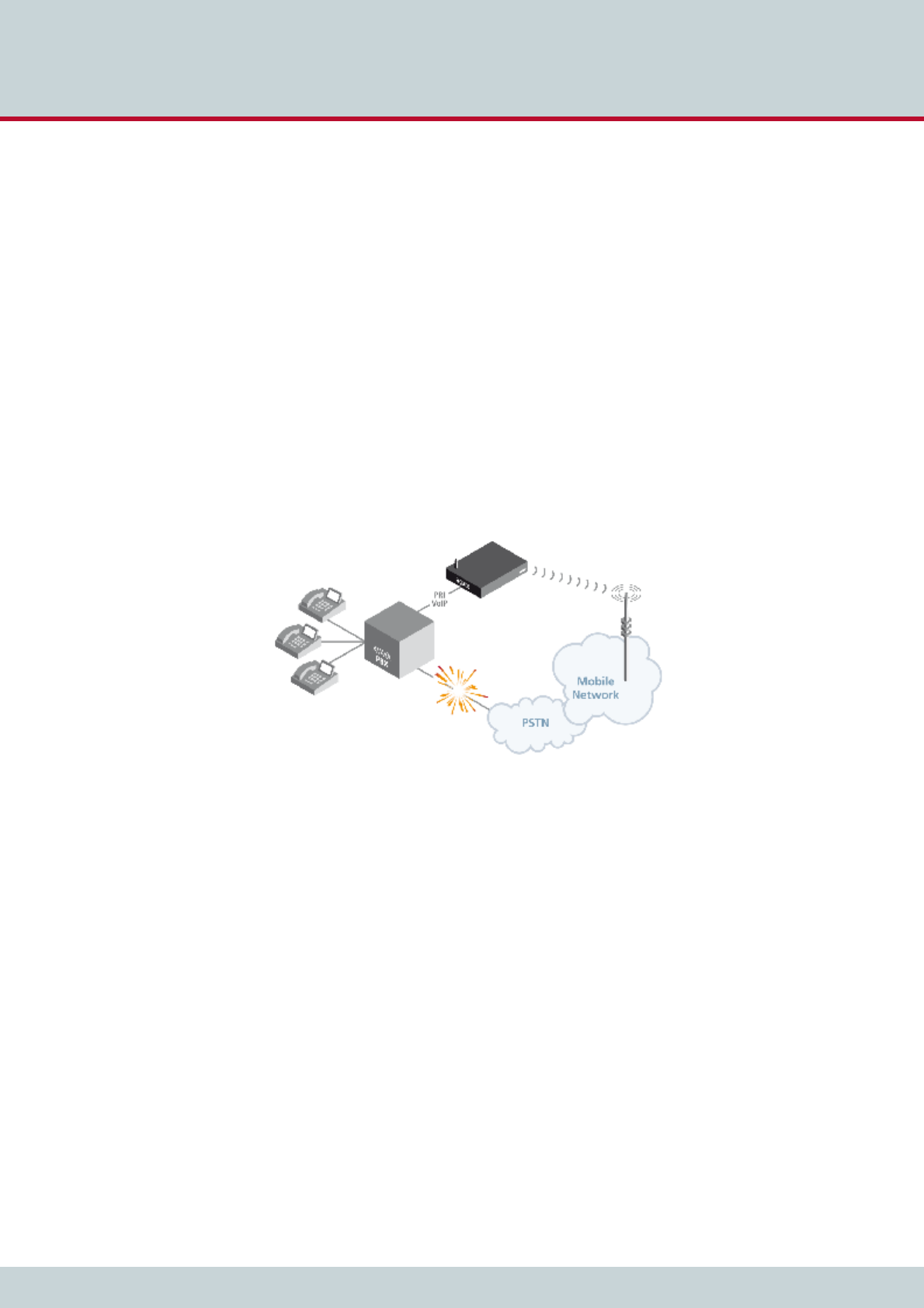
a) Failover application
In case of a landline connectivity failure, the PBX routes outgoing calls to the CELLX
which in turn forwards the calls directly to the mobile network.
Figure 3.1 Failover application
3Overview
Page 18CELLX 16.2
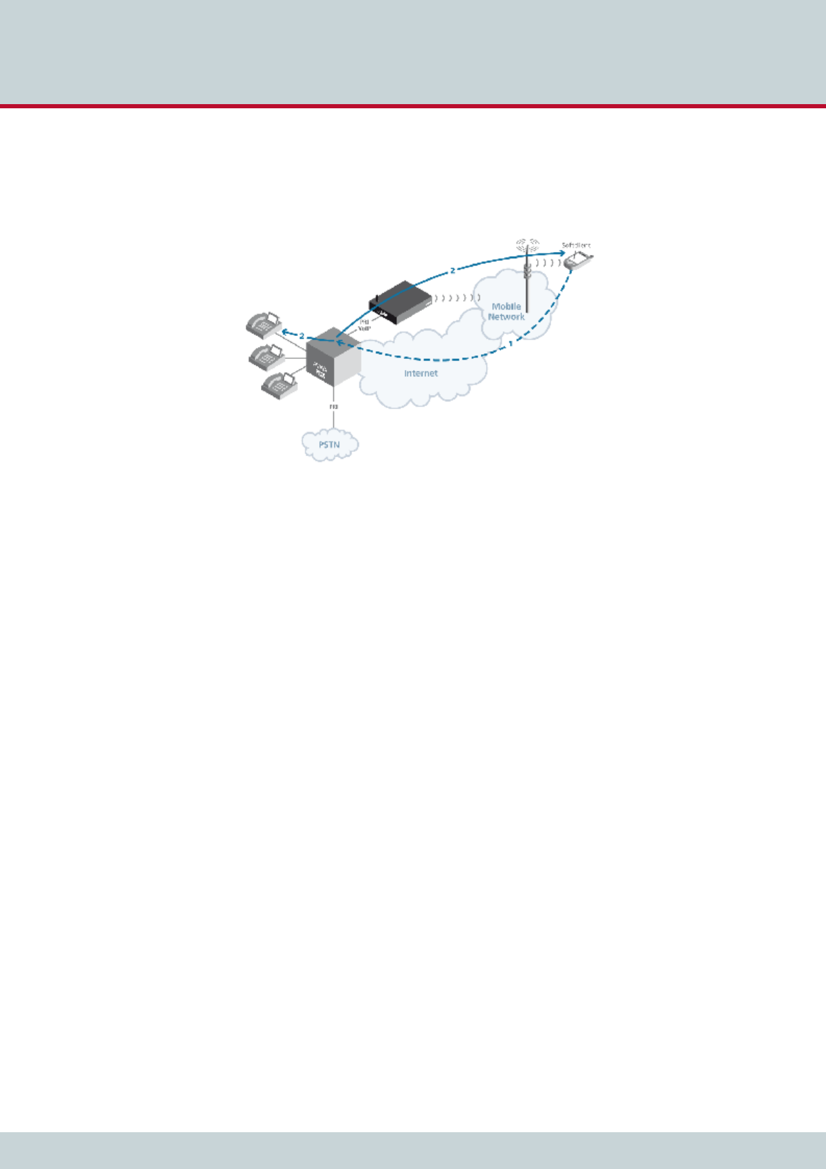
b) one-x mobile UC integration
A company’s cell-phone users have smart phones running Avaya’s one-X Mobile client.
The one-X mobile client requests a callback from the PBX via IP whenever these users
make a call. This callback is then routed through the CELLX. As soon as the callback is
answered, the PBX calls the B party and connects the call.
Figure 3.2 one-x mobile UC integration

4 Installation

4 Installation
Page 20CELLX 16.2
Follow the easy instructions to set up your CELLX in a matter of minutes. Implementation of
individual scenarios requires adjustments to the appropriate interfaces. Tips for basic settings
are described here. Links to relevant chapters are provided for more specific configuration
changes.
4.1 Checklist
The following checklist provides step-by-step installation instructions.
1. Check the package contents
2. Install the device
3. Connect the Ethernet
4. Connect the T1/E1 trunks (optional)
5. Connect the antennas
6. Using Quickstart, set the configuration (IP address)
7. Check functionality (using the LEDs)
8. Secure the LAN connection
9. Secure connection with the configuration program
4.2 Package contents
Your CELLX package contains the following components. Check the contents to make sure
everything is complete and undamaged. Immediately report any visible transport damages to
customer service. If damage exists, do not attempt operation without customer-service ap-
proval:
1 CELLX
1 power supply cable
1 crossover PRI cable
1 RJ-45 LAN cable with gray connectors; 3 meters
1 copy of quick installation instructions
1 CD containing Quickstart, GATE Manager, system manual and default configuration
files
Mobile antennas (optional)
4.3 Hardware description
Throughout this manual, the following boards will be referred to as Mobile Board, unless oth-
erwise specified:
4 GSM Board
CDMA Board
The CELLX is available in expansion levels from 4 to 32 mobile channels. The following pages
describe installation of the CELLX .
Figure 4.1 shows the rear view of a CELLX, which contains the following boards:
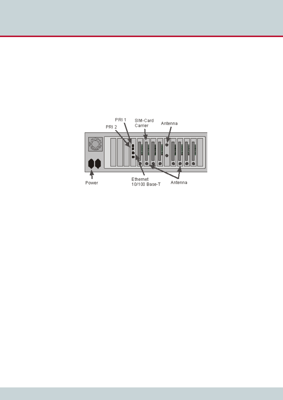
4 Installation
Page 21CELLX 16.2
From left to right:
Base Board
Mobile Board (for mobile channels 1-4)
Mobile Board (for mobile channels 5-8)
Mobile Board (for mobile channels 9-12)
Mobile Board (for mobile channels 13-16)
Optional Antenna Splitter Board
Mobile Board (for mobile channels 17-20)
Optional Mobile Board (for mobile channels 21-24)
Optional Mobile Board (for mobile channels 25-28)
Optional Mobile Board (for mobile channels 29-32)
Figure 4.1 4HU CELLX
4.4 Installation requirements
Before installing your CELLX, make sure you have the following connections in place:
Ethernet connection
Antenna connection(s)
Optional ISDN PRI connection to PBX
Power
Insert the SIM cards into the SIM card carrier, the SIM card carrier into the Mobile Board.
4.4.1 Ethernet wiring
To connect the CELLX’s Ethernet port to your local network, connect the system to an Ether-
net switch in your network. Use the three meter cable with gray connectors.
4 Installation
Page 22CELLX 16.2
4.4.2 PRI wiring
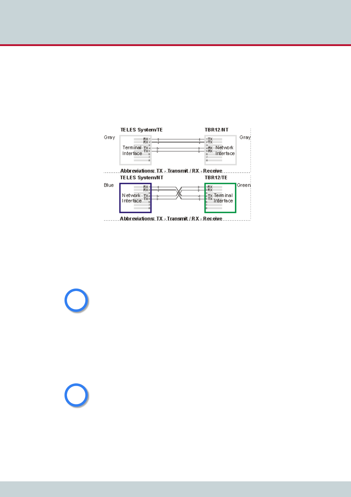
4.4.2.1 TELES to TBR12
If you are connecting an CELLX to T1/E1 and need to change the assignment of an adapter,
assign the pins as follows. Connectors on cables included with the CELLX will be gray for
TELES TE and gray for NT on the remote device, blue for TELES NT, and green for TE on the
remote device:
Figure 4.2 TELES to TBR12
4.4.3 Antenna connection
Plug an antenna cable into each of the SMA jacks. If the system contains a Antenna
Splitter Board, plug the antenna(s) in there. If not, plug them into the jacks on the
Mobile Board.
4.4.4 SIM card assignment
If your gateway is connected to a vGATE, the following information does not apply.
Each gateway has one or more slots for SIM card carriers. The SIM card carrier contains the
SIM cards for the individual mobile channels. Insert the SIM cards in the SIM card carrier and
then insert the SIM card carrier into the gateway.
SIM card carriers are available in two versions, SIM24 and SIM4, whereby the number shows
the number of available SIM card positions.
Antennas connected to the CELLX must be installed by a qulaified technician according to all
necessary safety requirements and the antenna’s installation specifications. The antenna
adaptor does not provide power surge protection.
i
i
You must configure the PINs in the pabx.cfg before inserting the SIM card carrier unless the
SIM has no PIN or the PIN is 0000.
i
i
4 Installation
Page 23CELLX 16.2
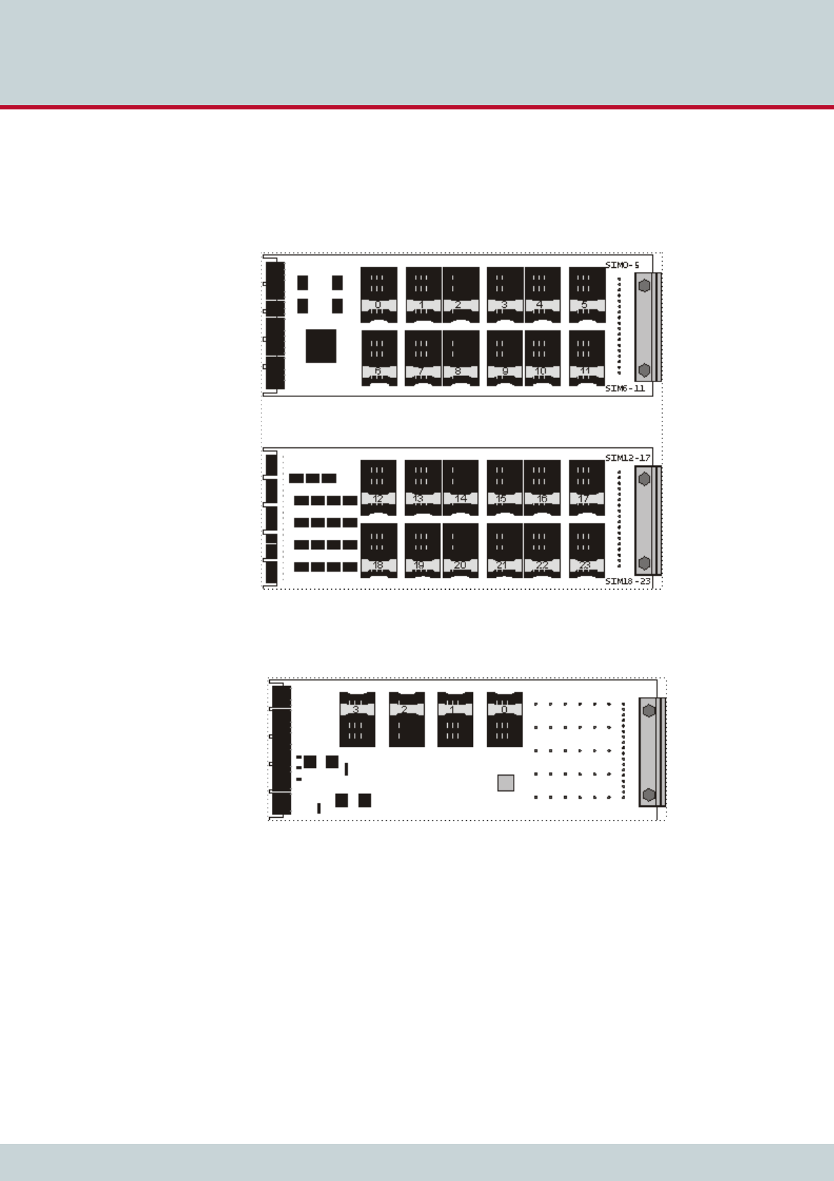
SIM cards are mounted on the front and back of the SIM24 module (Figure 4.3) or the front
of the SIM4 module (Figure 4.4). As a guide to help you distinguish top from bottom on the
SIM24 module, SIM0-5 and SIM12-17 are printed in the upper corner near the module’s han-
dle, as can be seen in Figure 4.3. The SIMs on the SIM4 module are numbered from right to
left, with one SIM assigned to each mobile channel in ascending order.
Figure 4.3 SIM24 module: front and rear view
Figure 4.4 SIM4 module
If a SIM24 carrier is used, one out of six SIM cards can be assigned to a mobile controller. To
configure that, an index has to be set in the pabx.cfg Subscriber line.
The following examples show how a SIM card at a certain position on the SIM24 carrier is
assigned to a defined mobile controller and what index it needs for assignment.
Table 4.1 shows the assignment to the mobile controllers 00 to 03. The 24 available SIM card
positions on the SIM24 carrier are listed in the body rows. The 6 different SIM cards which
are available for each mobile controller are indexed in the heading row. This index needs to
be entered in the pabx.cfg Subscriber line behind the SMSC entry. Example 4.1 shows that
the SIM card at position 0 on the SIM24 carrier is assigned to mobile controller 00 by giving

4 Installation
Page 24CELLX 16.2
it the index 1. The SIM card which is at position 1 on the SIM24 carrier is assigned to the mo-
bile controller 01 by also giving it the index 1. SIM card number 10 on the SIM24 carrier is
assigned to mobile controller 02 with the index 3. Analogously, SIM card number 11 is as-
signed to mobile controller 03 with the index 3.
The following corresponding example shows how SIM cards at position 4, 5, 6, and 7 on the
SIM24 carrier are assigned to the mobile controller 08 to 11. They all get the index 2 in the
Subscriber line.
Table 4.1 SIM card assignment to mobile controllers 1 (SIM24 carrier)
Index in Subscriber line 1 2 3 4 5 6
Controller/Subscriber00 0 4 8 12 16 20
Controller/Subscriber01 15 9 13 17 21
Controller/Subscriber02 2610 14 18 22
Controller/Subscriber03 3 7 11 15 19 23
Example 4.1 SIM card assignment to mobile controllers 1 (SIM24 carrier)
Subscriber00=TRANSPARENT GSM[0000,00000,+491770610000,1,1,1,SIM24] ALARM
Subscriber01=TRANSPARENT GSM[0000,00000,+491770610000,1,1,1,SIM24] ALARM
Subscriber02=TRANSPARENT GSM[0000,26202,+491770610000,3,1,1,SIM24] ALARM
Subscriber03=TRANSPARENT GSM[0000,00000,+491770610000,3,1,1,SIM24] ALARM
Table 4.2 SIM card assignment to mobile controllers 2 (SIM24 carrier)
Index in Subscriber line 1 2 3 4 5 6
Controller/Subscriber08 0 48121620
Controller/Subscriber09 15913 17 21
Controller/Subscriber10 2 610 14 18 22
Controller/Subscriber11 3711 15 19 23
Example 4.2 SIM card assignment to mobile controllers 2 (SIM24 carrier)
Subscriber08=TRANSPARENT GSM[0000,00000,+491770610000,2,1,1,SIM24] ALARM
Subscriber09=TRANSPARENT GSM[0000,00000,+491770610000,2,1,1,SIM24] ALARM
Subscriber10=TRANSPARENT GSM[0000,26202,+491770610000,2,1,1,SIM24] ALARM
Subscriber11=TRANSPARENT GSM[0000,00000,+491770610000,2,1,1,SIM24] ALARM

4 Installation
Page 25CELLX 16.2
In a SIM4 carrier, each SIM card corresponds with one mobile controller. In the pabx.cfg
Subscriber line each SIM card always gets the index 1, as shown in the example below.
4.5 Preparing for installation
Each computer that is to communicate with the CELLX requires a network connection. DHCP
can be used to automatically assign an IP address and the netmask. If you don’t use DHCP,
please have the following information for connection to your network available:
IP address in the local network for the CELLX to be configured
Netmask for the CELLX to be configured
Default gateway for CELLX to be configured
4.6 Hardware connection
Connect your computer with the local network
Connect the CELLX with the local network
If you choose to connect the CELLX to ISDN, use the ISDN connection cables included
in the package contents to connect the CELLX with your PBX and/or the PSTN according
to the required port configuration.
Connect the CELLX to the power supply.
4.7 Startup with Quickstart
Quickstart is an application that helps you to configure the IP settings of your CELLX quickly
and conveniently without changing any network settings on your computer.
Quickstart can be installed on any of the following operating systems:
Windows 2000
Windows XP
Windows Vista
Windows 7
If you are using any of these operating systems, please follow the instructions in this chapter.
4.7.1 Installing Quickstart
Make sure the GATE Manager is not running on your computer. To install Quickstart on your
computer, insert the CD and select Quickstart from the menu.
Example 4.3 SIM card assignment to mobile controllers (SIM4 carrier)
Subscriber00=TRANSPARENT GSM[0000,00000,+491770610000,1,1,1,SIM4] ALARM
Subscriber01=TRANSPARENT GSM[0000,00000,+491770610000,1,1,1,SIM4] ALARM
Subscriber02=TRANSPARENT GSM[0000,26202,+491770610000,1,1,1,SIM4] ALARM
Subscriber03=TRANSPARENT GSM[0000,00000,+491770610000,1,1,1,SIM4] ALARM
Bear in mind that the preconfigured CELLX’s default IP address is 192.168.1.2. If it is already
being used in your local network, you must run Quickstart without a connection to your local
network. This can occur using a back-to-back Ethernet connection from your computer to the
CELLX. If the desired IP address for the CELLX is not in your network, you must assign your
computer a temporary IP address from this range.
i
i
4 Installation
Page 26CELLX 16.2
When asked if you want to install components on your machine, click Install.
Click Next in the introduction window to begin installation of the Quickstart.
Once installation begins, click Next to install Quickstart in the predefined folder. To install it
in another location, click Browse and select a folder from the browser that appears. Then
click Next.
Click Close to exit when installation is complete.
4.7.2 Configuration with Quickstart
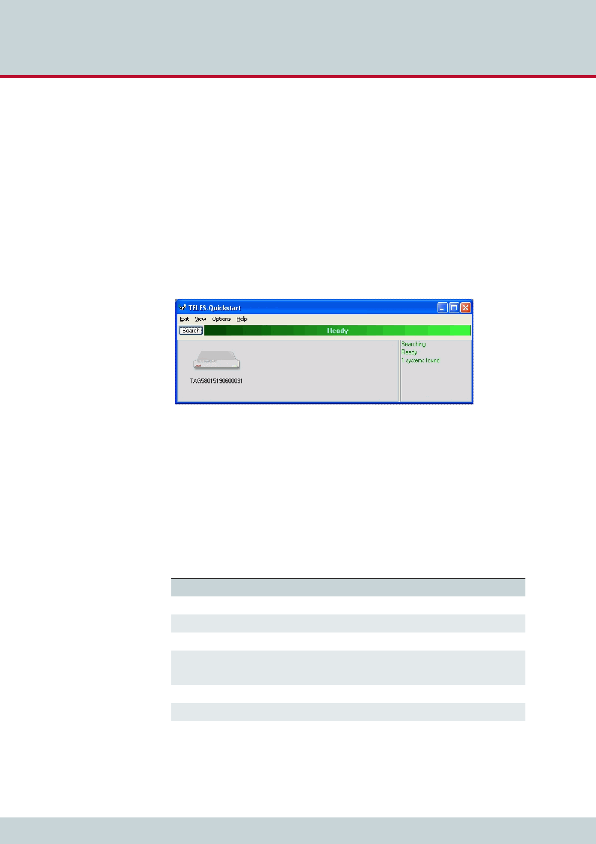
Now you can use Quickstart, to set up your CELLX’s IP configuration. Open Quickstart.exe.
The program will automatically search for your CELLX in the local network. For Quickstart, the
source UDP port is 57445. It might be necessary to change the firewall rules on your system.
Click Search if you would like to restart the search. When the program has found your CELLX,
it will appear in the window. As soon as it appears, you can end the search by clicking Stop.
Figure 4.5 Quickstart
The system’s icon will appear in gray if it is unconfigured. Once it has been configured, it will
appear in green. The serial number appears as the system’s name. The CELLX is partially pre-
configured. The configuration files pabx.cfg and route.cfg are already on the system. Only
the system’s IP-related entries must be set. Individual port adjustments are to be made man-
ually later. Port properties can be changed and parameters can be assigned then.
To change the appearance of the window, click Large Icons, Small Icons or Details in the
View menu. In the following description, we will use the Details View, which contains the
following columns:
Table 4.3 Quickstart details view columns
Heading Definition
Identifier This column lists the CELLX’s serial number.
IP Address This column lists the CELLX’s IP address.
Configured An X means the CELLX contains the configuration files.
# of VoIP Ctrls This column lists the number of VoIP Modules installed in the CELLX.
Each VoIP Module represents one VoIP controller.
VoIP Channels This column shows the number of VoIP channels per VoIP Module.
Type Lists the type of the system.
4 Installation
Page 27CELLX 16.2
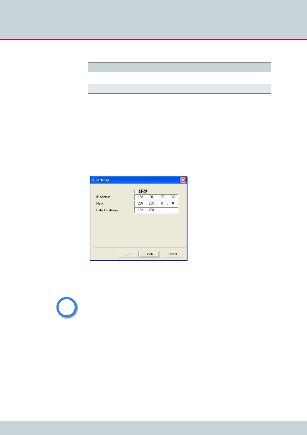
In the Options menu, you can suppress or activate ICMP ping to test the Internet connection.
To perform the initial configuration of the system, double-click the icon or right-click and se-
lect Configure. The IP Settings dialog will appear. If you want the gateway to use a dynamic
IP address, activate the checkbox DHCP. This will deactivate the next three lines. Your DHCP
server will automatically provide all of the other necessary information. If you do not have a
DHCP server, leave the DHCP checkbox empty. The default IP address appears in the IP Ad-
dress box. Enter a new IP address. If the address you enter already exists in the network, you
will be notified to choose another address at the end of the configuration process. Enter the
system’s netmask in the Mask dialog box. Enter the IP address for the Default Gateway.
Click Finish.
Figure 4.6 Quickstart configuration: IP settings
Now the IP settings are configured; all other processes run automatically. First the system’s IP
address will be changed and then the system will start with the new IP address.
If you right-click the system’s icon in the main window and choose Temporarily Configure
IP Address, only the IP address for the system’s first Ethernet interface and the netmask will
be temporary changed. This can be helpful if you want to set up local remote access to the
Box An X means the system is a VoIPBox BRI.
CF Mounted An X means the CELLX contains a compact flash disk.
Table 4.3 Quickstart details view columns (continued)
Heading Definition
There is no internal time generation for the system when the power is interrupted. That means
the default time is used when the system is restarted or rebooted! Therefore it is important to
set the system time with an NTP server.
If the system is connected via ISDN, a clock may come from the network connected to the cor-
responding port. Enter TIME in the pabx.cfg’s Subscriber line for the TE port to retrieve the
time from the port.
i
i
4 Installation
Page 28CELLX 16.2
system and use other IP settings on the remote device than the system’s IP configuration in
the network. Bear in mind that the functions on the system’s first Ethernet interface work
with the new settings.
Now you can complete the system’s configuration using the GUI (please see Chapter 4.8 Star-
tup via GUI on page 28).
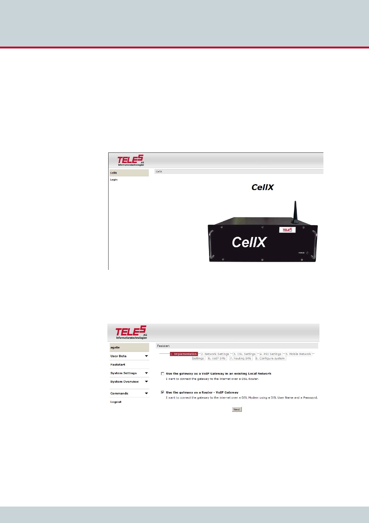
4.8 Startup via GUI
System configuration can occur via the GUI.
Figure 4.7 GUI
We recommend you use Internet Explorer 6/7/8. Simply open a browser, enter the system’s
IP address in the address bar, and click Login in the navigation menu on the left. Enter the
username teles-carrier and the password tcs-carrier to access the system.
Figure 4.8 GUI faststart
Using the navigation menu on the left, click Faststart to configure the system. Follow the
steps as they appear.
4 Installation
Page 29CELLX 16.2
To edit the default configuration, follow the directions in Chapter 5 Configuration files. Up-
load the configuration files into the /boot directory.
4.9 LED functionality
4.9.1 Ethernet port LEDs
Each ethernet port has 2 LEDs to show its status. The left LED blinks to indicate data traffic.
The right LED is currently not used.
4.9.2 Base Board PRI port LEDs
Each PRI port has one red and one green LED to show the port’s status.
The red LED displays the status of the bypass relay that connects the ports with each other
when the relay between the PRI ports is off. That means when the system is connected be-
tween a PBX and the PSTN, it is transparent when the LED is red.
The green LED displays whether or not layer 1 is active on the PRI port’s connected cable.
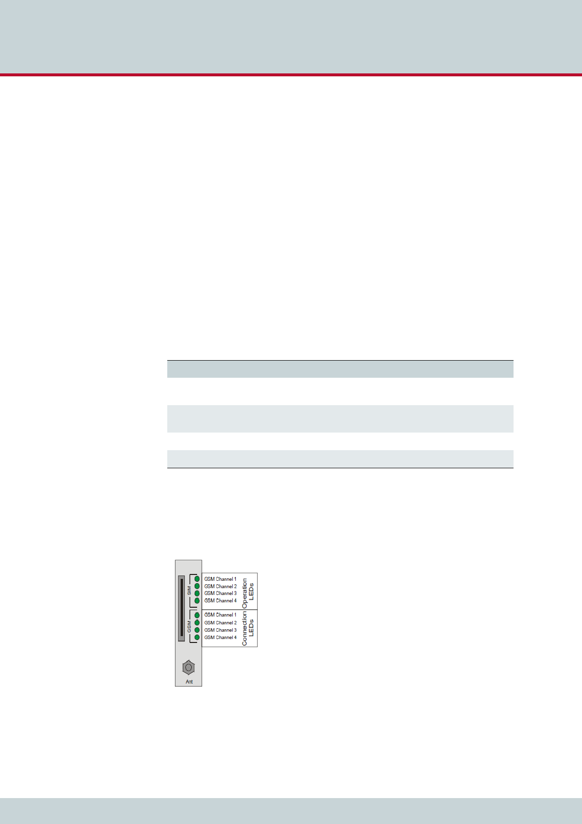
4.9.3 Mobile Board SIM card LEDs
On the spine of the Mobile Board, to the right of the SIM card module, two columns of green
LEDs display the status of each mobile channel.
Figure 4.9 Mobile Board SIM card LEDs
Table 4.4 Base Board PRI Port LEDs
LED Description
Red ON The system and bypass relay are inactive (normal-
ly during the startup phase).
Red OFF The system has started and the bypass relay is ac-
tive.
Green ON Layer 1 is active.
Green OFF Layer 1 is inactive.

4 Installation
Page 30CELLX 16.2
The LEDs in the upper column show the general operational status of the SIM cards, while
the status of the mobile channels is displayed in the lower column.
Table 4.5 contains a description of the LEDs and what they mean:
Table 4.5 Mobile Board LEDs
Operational Status Connection Status Definition
OFF OFF The mobile channel is not oper-
ational because:
No external power supply
SIM module slot is empty
No SIM card
OFF Blinking slowly Not possible
OFF Blinking quickly Not possible
OFF ON Not possible
Blinking slowly OFF The SIM card is attached, but
the mobile channel is not oper-
ational because:
Mobile channel is in logon
phase
Mobile channel’s status is
unknown
Blinking slowly Blinking slowly Not possible
Blinking slowly ON Not possible
Blinking quickly OFF The mobile channel is not oper-
ational because:
SIM card has been blocked
Reception field strength
below limit
Blinking quickly Blinking slowly Not possible
Blinking quickly Blinking quickly Status during initializing phase
(system start up). Display
changes when status of mobile
changes.
Blinking quickly ON Not possible
ON OFF The mobile channel is opera-
tional, the SIM card has logged
on.
ON Blinking slowly Not possible
ON Blinking quickly The mobile channel is opera-
tional, the SIM card has logged
on, a connection is being set up
on this channel
ON ON The mobile channel is opera-
tional, the SIM card has logged
on, a connection has been set
up on this channel
4 Installation
Page 31CELLX 16.2
4.10 Remote access and access security
After the system has been configured and all cables are connected, remote administration
and maintenance can occur with the GATE Manager (Chapter 4.10.1), the GUI
(Chapter 4.10.2)or via FTP (Chapter 4.10.3).
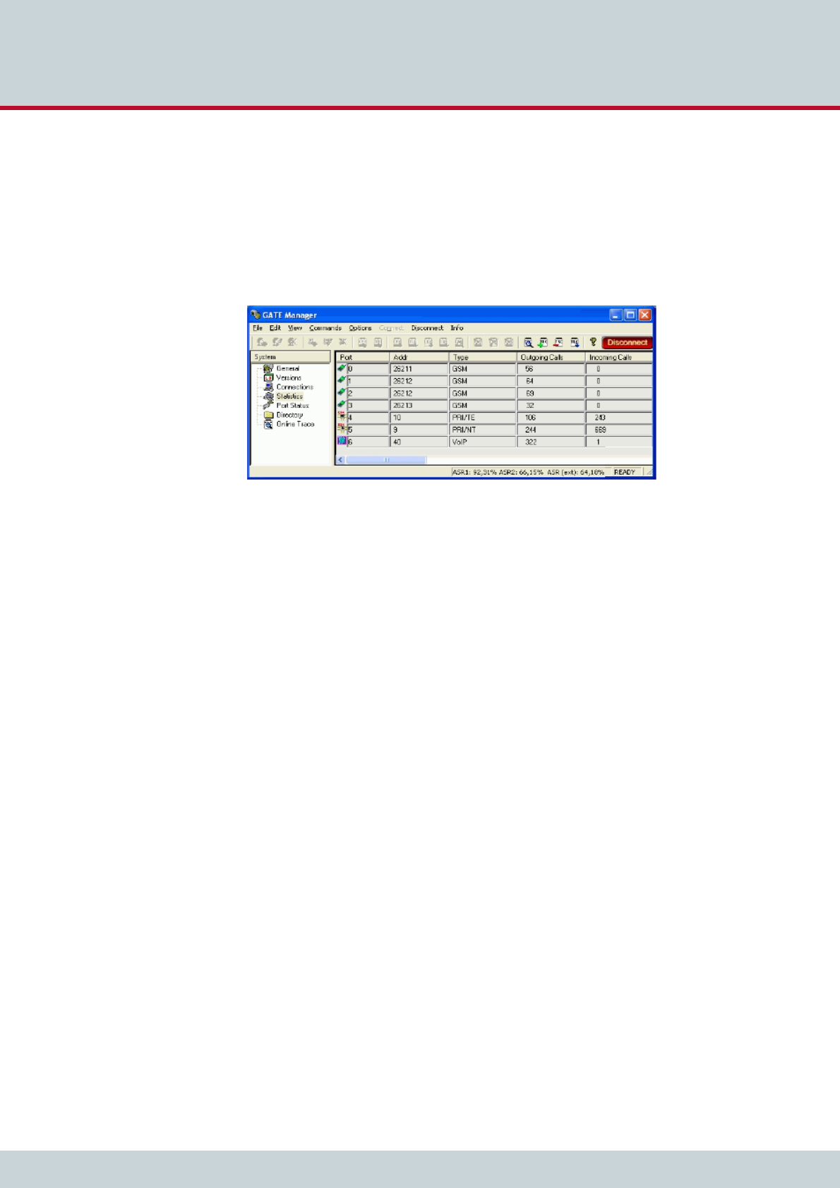
4.10.1 GATE Manager
Figure 4.10 GATE Manager
The GATE Manager administration and maintenance software offers a broad range of func-
tions. The GATE Manager is user friendly and can be customized to suit your needs.
The following maintenance functions are possible:
Display system information and network element status.
Retrieve and display configuration files.
Restart network elements.
Use of a trace option for checking functions and fault diagnosis. Option to use an
external tool, for example to display and break down trace data.
Update the system software and configuration tables.
Retrieve CDRs (Call Detail Records).
Display the current connections (status).
Display statistical information for network elements and interfaces.
Display the status of the interfaces.
Use the CD enclosed in your package contents to install the GATE Manager. For a detailed
description of installation and implementation of the GATE Manager, please refer to the
GATE Manager and Utilities Programs Manual.
GATE Manager remote access can occur via IP or ISDN. GATE Manager access via IP uses port
4444 as source TCP port and port 4445 as destination port. You can change the port in the
pabx.cfg file using the following parameter: MoipPort=4567.
Bear in mind that the same port must be configured in the GATE Manager. The TCP port can
be specified behind the IP address and a colon: IP:172.20.25.5:4567.
In the default configuration, ISDN remote access is disabled. To configure the system so that
certain data calls are received as remote administration calls, make the following changes in
the pabx.cfg:
RemoteCode=BBB
Add the following mapping to the route.cfg:
MapAll<direct>=BBB DATA
Make the following entries in the route.cfg if the system is to handle all ISDN data calls as
remote-administration calls:
4 Installation
Page 32CELLX 16.2
MapAll?=BBB DATA
4.10.2 Graphical user interface (GUI)
Remote access can occur via the GUI. Even users with little experience can easily configure
standard system settings with this interface. Simply open a browser and enter the system’s IP
address in the address bar.
Figure 4.11 GUI
The following administrative levels apply:
Carrier mode (full access)
User: teles-carrier
Password: tcs-carrier
All configuration pages can be accessed in this mode.
Example 4.4 Carrier mode (full access)
[httpd]
PwdUser=k24X0sdc.uMcM
PwdAdmin=k2UMj19qtovzI
PwdCarrier=k2jryo6Xd5vN6
Never copy these entries from one system to another, as the encryption is unique for each sys-
tem.
i
i

4 Installation
Page 33CELLX 16.2
Administrator Mode
User: teles-admin
Password: tcs-admin
This access level is for the user network’s administrator. All IP and routing entries, with the
exception of VoIP carrier entries, can be set here.
Read-Only Mode
User: teles-user
Password: tcs-user
No configuration changes can be made at this level. Only status and statistics can be retrieved.
Of course, these configuration levels correspond with the most important scenarios. The pass-
words are saved in the ip.cfg in encrypted form:
PwdCarrier=<crypt>
PwdAdmin=<crypt>
PwdUser=<crypt>
The user interface is divided into the following main sections:
All of the user interface’s pages contain Help buttons and links to the online help, which pro-
vides a detailed description of all of the individual configuration settings.
4.10.3 FTP
Remote access can also occur via FTP. You can use FTP to transfer configuration files. You can
also carry out functions and traces with raw commands. Use the username teles and the
defined password to connect to the system with FTP.
Table 4.6 GUI: sections
Section Description
User Data Here you can change the user passwords and the language for
the GUI.
Faststart Faststart helps you to configure the system settings of
your quickly and conveniently.
System Settings IP Settings: Settings for the Ethernet interfaces and related
services.
Port Settings: Settings for the ECOTEL GSM ports.
VoIP Settings: VoIP settings for the SIP or H.323 carrier.
Telephony Routing:Routings for telephone numbers.
System Overview Overview of system information and drivers.
Commands Here you can activate a configuration or restart the system.

4 Installation
Page 34CELLX 16.2
The following entries in the pabx.cfg ensure the security of your FTP access:
Once you have access to the system, you will be in the folder /home/teles. To upload or
download configuration files change to the directory /boot. To download log files, change
to the directory /data if the system contains a flash disk. Otherwise change to the directory
/boot.
The following commands can be carried out via FTP access:
If your FTP client does not support the site command, try “literal site” instead.
4.10.4 Setting a password for remote access
The following entry ensures the security of your remote access. Use the mkpwd.exe tool to
generate the password. You will find it on the enclosed CD in the directory pwd.
Start the program in a command window with the entry mkpwd <password>. The output
shows the encrypted password. Enter the encrypted password in the configuration file
pabx.cfg’s parameter line as follows.
Table 4.7 FTP security entries
FTP Security
FtpdPort=<port>
Defines the FTP access port (default 21).
RemotePassword=<password>
Defines the password for FTP and GATE Manager access. Please refer to Chapter 4.10.4 for in-
structions on how to enter an encrypted password in the pabx.cfg. If you do not define a pass-
word, access to the system via GATE Manager occurs without a password, and FTP access occurs
with the default password tcs-ag.
Table 4.8 FTP commands
Command Function
site xgboot Boots the entire system.
site xgact Activates the configuration.
site xgact 1-19 Activates the Night section corresponding with
the number 1-19.
site xgtrace 0 Deactivates trace.
site xgtrace 1 Activates layer 2 trace.
site xgtrace 2 Activates layer 3 trace.
Example 4.5 Password for remote access
RemotePassword=<crypt>

4 Installation
Page 35CELLX 16.2
When the file has been transferred to the system and the configuration has been activated,
access to the system can occur only with the password. Don’t forget to memorize the pass-
word!
If you do not define a password, access to the system via GATE Manager occurs without a
password, and FTP access occurs with the default password tcs-ag.

5 Configuration files
5 Configuration files
Page 37CELLX 16.2
This chapter describes the basic setup and the most commonly used entries for the configu-
ration files. Configuration of CELLXs is managed in the following three files:
The default configuration with the IP address 192.168.1.2 is active when the files are not on
the system. You can configure the files using GATE Manager or via FTP (user teles, password
tcs-ag). If you use the GUI to make configuration changes, the files will be adjusted automat-
ically.
Make sure you secure the system with new passwords following configuration and remember
to memorize the passwords!
These configuration files contain all system-specific settings and are used when the system
starts. Comments included in these files must begin with a semicolon. They do not need to
be at the beginning of a line. Configuration files must end with an empty line.
Please save a backup of the files pabx.cfg and route.cfg before starting configuration.
The configuration files follow these conventions: Individual files are divided into sections.
These sections always begin with a line entry in square brackets. The basic required sections
are in these files:
Table 5.1 Configuration files
File Function
ip.cfg This file is for the basic configuration of the
Ethernet interfaces.
pabx.cfg This file is for system-specific and port-specific
settings.
route.cfg This file is for call-routing entries.
Changing configuration data and/or SIM card positions may lead to malfunctions and/or mis-
routing, as well as possible consequential damage. All changes are made at own risk. TELES
is not liable for any possible damage out of or in relation with such changes. Please do there-
fore thoroughly check any changes you or a third party have made to your configuration.
i
i
i
i
Table 5.2 Required configuration file sections
Section File Function
[System] pabx.cfg
route.cfg
ip.cfg
This section contains the sys-
tem’s basic settings.
[Night<num>]
EXAMPLE:
[Night1]
[Night2]
pabx.cfg
route.cfg
This section contains time de-
pendent entries that only apply
for limited times.
[emac0] ip.cfg This section contains the IP
configuration for the first
Ethernet interface.

5 Configuration files
Page 38CELLX 16.2
5.1 Configuration file ip.cfg
The basic settings for the two Ethernet interfaces are entered here. One interface usually suf-
fices. The second interface can be used for special requirements, for example as a hub port,
DSL router or vLAN interface. Generally, these settings are entered once and then left un-
changed.
This file contains the following sections, which must appear in the order given:
5.1.1 System section configuration
The [System] section contains entries that define the default gateway and/or special routing
entries.
To define the standard gateway, use the following entry to set the IP address:
DefaultGw=<ip addr>
Table 5.3 Sections in the ip.cfg file
Section Function
[System] (required) This section contains entries that define the default gateway
and/or special routing entries.
[emac0] (required)
[emac1] (optional)
The Ethernet Media Access Controller section(s) define the
physical Ethernet interface(s).
[nat] (optional) This section includes settings for Network Address Translation.
[bridge0] (optional) These section(s) contain settings for the second Ethernet con-
troller in bridge mode.
[pppoe<x>] (optional) These sections contain settings for direct connection between
the system and the DSLAM when the PPPoE protocol is used.
<x> can be 0 or 1.
[firewall] (optional) This section contains settings for activating the system’s fire-
wall.
[altqd] (optional) This section enables prioritization of VoIP packets in the CELLX
through an IP network using bandwidth control.
[dhcpd] (optional) This sections contains a list of parameters and settings for the
DHCP server in the system. It is divided into global settings for
the server and parameters for the DHCP subnet.
[xppp<x>] (optional) This section contains settings for point-to-point dial-up setup
via ISDN.
[vlan<x>] (optional) These section(s) contain settings for the virtual networks. <x>
can be anything from 0 to 9.
Example 5.1 System section configuration 1
[System]
DefaultGw=192.168.1.254

5 Configuration files
Page 39CELLX 16.2
If you must route specific net ranges to gateways other than what is defined in the default
route, make the following entries in the [System] section:
Route=<target range> -netmask <ip mask> <ip gateway>
If only certain routes apply, leave the line DefaultGw empty.
5.1.2 Ethernet interface configuration
The system includes two Ethernet interfaces (emac0 and emac1). Only the first is active in the
default configuration. Therefore, make sure you plug the cable into the right controller. The
second Ethernet interface can be configured as needed.
The following settings are possible for the sections [emac0] (matched to the first Ethernet
controller) and [emac1] (matched to the second Ethernet controller):
IpAddress=<ip addr>/<netmask>
The IP address is entered in decimal notation, followed by a slash (/) and the netmask in bit
notation.
The following entry is used to allocate an IP address via DHCP:
IpAddress=dhcp
The following entry is used in the [emac1] section if operation of the system occurs in bridge
mode.
IpAddress=up
5.1.3 GUI settings
The following parameter is used to change the GUI port in the section [httpd] (default 80):
GuiPort=<num>
Bear in mind that the passwords for different access levels are not set here. The encrypted
passwords are stored here and can only be changed via GUI (see Chapter 4.10.2 on page 32).
Example 5.2 System section configuration 2
[System]
DefaultGw=192.168.1.254
Route=10.0.0.0 -netmask 255.0.0.0 192.168.1.1
Example 5.3 Ethernet interface configuration
IpAddress=192.168.1.2/24
Example 5.4 GUI settings
[httpd]
GuiPort=80
PwdUser=k24X0sdc.uMcM
PwdAdmin=k2UMj19qtovzI
PwdCarrier=k2jryo6Xd5vN6

5 Configuration files
Page 40CELLX 16.2
5.1.4 Bridge configuration
A bridge can connect two networks with each other. A bridge works like a hub, forwarding
traffic from one interface to another. Multicast and broadcast packets are always forwarded
to all interfaces that are part of the bridge. This can occur on the Ethernet or VLAN level:
BrConfig=add <interface-x> add <interface-y> up
Activating another Ethernet interface in this way is useful, for example, when the Ethernet
switch does not have any more ports available for connection of the system. You can simply
unplug a cable and plug it into the system’s second Ethernet interface.
5.1.5 NAT configuration
The NAT (Network Address Translation) module translates IP addresses from the local net-
work to an IP address or range on a public interface. All rules are defined in the [nat] section:
Example 5.5 Bridge configuration
[bridge0]
BrConfig=add emac0 add emac1 up
Table 5.4 NAT configuration
map=<interface> <local network address/mask> -> <public network address/mask> <op-
tional entries>
This parameter maps the IP address in the local network to the IP address in the public network.
<interface> Defines the translated interface or protocol:
emac1 The system’s second Ethernet interface
pppoe0 Protocol used for DSL connections
xppp<0> Protocol used for ISDN and CDMA dial-up
connections
<local network address/mask> The IP address is entered in decimal notation, followed by a
slash (/) and the netmask in bit notation. The entire local net-
work range is configured.
<public network address/mask> Defines the public network range, with network address and
mask (usually exactly one address), into which the local IP ad-
dresses are to be translated. The IP address is entered in dec-
imal notation, followed by a slash (/) and the netmask in bit
notation.
<optional entries> Special rules can be defined for some services or protocols.
The system can serve as a proxy for FTP:
proxy port ftp ftp/tcp
Special ports for the public address(es) can be assigned for the
protocols TCP and UDP. The range is defined by the start and
end ports:
portmap tcp/udp <start port>:<end port>
If no optional entry is defined, all other addresses will be
translated without special rules.
rdr=<interface> <public network address/mask> port <port> -> <local network address/
mask> port <port_number> <protocol>
This parameter sends packets from one port and IP address to another.

5 Configuration files
Page 41CELLX 16.2
The following NAT settings are for a system in which PPPoE (DSL) is used toward the Internet.
The local network range 192.168.1.0 Class C is translated with the following rules:
The proxy mode is used for FTP.
All other TCP and UDP packets are mapped to the external ports 40000 to 60000.
There are no special rules for any other services.
Incoming requests to port 80 and 443 in the public IP address 192.168.1.100 are
redirected to ports 80 and 443 in the local IP address 192.168.1.100.
5.1.6 PPPoE configuration
The protocol Point-to-Point over Ethernet is used for DSL communication with the DSLAM.
That means the system can connect directly with a DSL modem.
All necessary information for setup of the PPPoE connection is defined in the [pppoe<x>] sec-
tion. That means username, password and authentication protocol are set here. The Ethernet
interface is emac1 and the gateway can also be defined. The parameter PppoeIf defines the
physical Ethernet interface used (always emac1). The settings are entered as follows: Bear in
mind that configuration of the firewall, the NAT module and prioritization of the VoIP packets
must be considered when routing voice and data through the DSL line.
<interface> Defines the translated interface or protocol:
emac1 The system’s second Ethernet interface
pppoe0 Protocol used for DSL connections
Protocol used for ISDN and CDMA dial-up connections
<public network address/mask> Defines the public network range, with network address and
mask (usually exactly one address), into which the local IP ad-
dresses are to be translated. The IP address is entered in dec-
imal notation, followed by a slash (/) and the netmask in bit
notation.
<port> Defines the port number.
<local network address/mask> The IP address is entered in decimal notation, followed by a
slash (/) and the netmask in bit notation. The entire local net-
work range is configured.
<protocol> Defines the protocol. tcp and udp are possible.
watch=<interface 1> <interface 2> ... <interface n>
Enter all interfaces that you have configured. If an interface is activated, the NAT table is resetted to
ensure correct IP address translation.
Table 5.4 NAT configuration (continued)
Example 5.6 NAT configuration
[nat]
map=emac1 192.168.1.0/24 -> 0/32 proxy port ftp ftp/tcp
map=emac1 192.168.1.0/24 -> 0/32 portmap tcp/udp 40000:60000
map=emac1 192.168.1.0/24 -> 0/32
rdr=emac1 0/0 port 80 -> 192.168.1.100 port 80 tcp
rdr=emac1 0/0 port 443 -> 192.168.1.100 port 443 tcp

5 Configuration files
Page 42CELLX 16.2
The following entry will create the interface pppoe0, with the username user and the pass-
word pwd. The PAP authentication protocol is used. The default route occurs via DSL.
5.1.7 Firewall settings
In the following example, only port 4445 allows incoming connections from the IP address
192.168.1.10. All others will be blocked.
Example 5.7 PPPoE configuration
[pppoe0]
PppoeIf=emac1
User=user
Pwd=pwd
AuthProto=pap
Route=0.0.0.0
The firewall settings provide options for limiting or denying access to and from the system. If
you do not configure this section, the firewall is inactive and access is unlimited. Make sure
you configure the firewall rules carefully. The rules are processed from top to bottom. If you
use the option quick, you will break the sequence. We recomend that you put the most re-
strictive rule at the end of the configuration.
i
i
Example 5.8 Firewall settings 1
[firewall]
fw=pass in quick on emac0 proto tcp from 192.168.1.10/32 to any port
eq 4445 flags S keepstate keep frags
fw=block in log quick on emac0 all
Table 5.5 Settings in the [firewall] section of the ip.cfg
[firewall]
fw=<mode> <direction> <list>
<mode> Two modes are possible for permitting or deny-
ing access:
pass permit access
block deny access
<direction> Possible directions are in and out:
in external to internal
out internal to external
<list> All other entries specify the other settings for the
corresponding firewall rules and are optional.
The order in the line is as listed below:
log
Records non-matching packets.

5 Configuration files
Page 43CELLX 16.2
quick
Allows short-cut rules in order to speed up the filter or override later rules. If a packet matches
a filter rule that is marked as quick, this rule will be the last rule checked, allowing a short-circuit
path to avoid processing later rules for this packet. If this option is missing, the rule is taken to
be a "fall-through rule, meaning that the result of the match (block/pass) is saved and that pro-
cessing will continue to see if there are any more matches.
on <interface>
The firewall rule is used only for the defined interface (for example emac0, pppoe0).
from <networkaddress/mask>
to <networkaddress/mask>
from defines the source IP-address range for incoming packets. to defines the target IP-address
range for outgoing packets. The IP address appears in decimal notation, followed by a slash (/)
and the netmask in bit notation. any stands for all IP addresses (example: to any).
NOTE: If you use the rule pass in/out in combination with the option from <ip> to <ip>,
you must specify a protocol number with proto and a port number. If you not specify the
port, the system may not be reachable.
EXAMPLE:
fw=pass in quick on pppoe0 proto tcp from any to any port eq 4445
proto <protocol>
defines the protocol, for which the rule is valid (example: proto tcp, proto udp, proto icmp).
port eq <num>
<num> defines the port as number (example: port eq 4445).
keep state
Ensures that the firewall checks packets from the beginning to the end of a session. This is nec-
essary, as the firewall cannot process when a session begins or ends.
flags S
Only syn. packets are accepted and recorded in the state table. In conjunction with keep state,
packets from sessions that have been inactive will also be routed. The advantage of this entry is
that random packets will not be accepted.
keep frags
Fragmented packets are also routed.
Table 5.5 Settings in the [firewall] section of the ip.cfg (continued)
[firewall]
fw=<mode> <direction> <list>

5 Configuration files
Page 44CELLX 16.2
5.1.8 Bandwidth control
In many implementation scenarios, the CELLX in router mode (for example as DSL router)
sends voice and data traffic through a connection with limited bandwidth. This can lead to
lost voice packets that arrive too late to be used in the voice stream. To avoid lost packets,
this QOS setting prioritizes packet transmission. You must set the priority for voice signaling
and for the voice packets. That means you must prioritize SIP/H.323, RTP and RTCP. You will
find the ports used in Table 5.14, in the following entries:
H225Port
SipPort
VoipRtp Port
VoipRtpPortSpacing
Different ports are used for RTP and RTCP, depending on the configuration.
The parameter VoipRtpPort shows the first RTP port used. The corresponding RTCP port is the
next one up. The parameter VoipRtpPortSpacing shows the next RTP port (RTP port + port
spacing).
Example 5.9 Firewall settings 2
[firewall]
; loopback
fw=pass in quick on emac0 all
fw=pass out quick on emac0 all
; traffic to outgoing
fw=pass out quick on pppoe0 proto tcp all flags S keep state keep frags
fw=pass out quick on pppoe0 proto udp all keep state keep frags
fw=pass out quick on pppoe0 proto icmp all keep state keep frags
; incoming traffic
fw=pass in quick on pppoe0 proto tcp from 10.4.0.0/16 to any port eq 21 flags S
keep state keep frags
fw=pass in quick on pppoe0 proto tcp from 10.4.0.0/16 to any port eq 23 flags S
keep state keep frags
fw=pass in quick on pppoe0 proto tcp from 10.4.0.0/16 to any port eq 4445 keep
state
; icmp traffic
fw=pass in quick on pppoe0 proto icmp all keep state
; other will be blocked
fw=block in log quick on pppoe0 all
fw=block out log quick on pppoe0 all
Table 5.6 Settings in the [altqd] section of the ip.cfg
Interface=<interface> bandwidth <bw> priq
Defines the interface for which the rule applies.
<interface> Sets the interface for which prioritization applies
(e.e. pppoe0).
<bw> Sets the bandwidth that is available on the inter-
face in Kbit/s (for example 256K).
priq Priority qeueing. A higher priority class is always
served first.
classPrio=<interface> <class> root priority <prio>

5 Configuration files
Page 45CELLX 16.2
In the following example, prioritization is set for a thirty-channel VoIP connection. The SIP sig-
naling port 5060 and the RTP/RTCP ports 29000 to 29059 are prioritized at level 7. All other
services are set at level 0.
Defines the priority of the filter entries.
<class> Two types can be set:
realtime_class (VoIP packets)
regular_class (data packets)
<prio> Enter a value between 0 and 15. The higher the
value (for example 15), the higher the priority.
Filter=<interface> <class> <values>
Defines the individual rules for the class.
<values> The individual values are divided into the follow-
ing entries. A 0 can be entered as a wildcard, in
which case all values are possible:
<dest_addr> (can be followed by netmask
<mask>)
<dest_port>
<src_addr> (can be followed by netmask
<mask>)
<src_port>
<protocol tos value>:
6 for TCP
17 for UDP
Table 5.6 Settings in the [altqd] section of the ip.cfg (continued)
Interface=<interface> bandwidth <bw> priq
Example 5.10 Bandwidth control
[altqd]
interface pppoe0 bandwidth 512K priq
class priq pppoe0 realtime_class root priority 7
filter pppoe0 realtime_class 0 5060 0 0 0
filter pppoe0 realtime_class 0 0 0 5060 0
filter pppoe0 realtime_class 0 29000 0 0 17
filter pppoe0 realtime_class 0 0 0 29000 17
filter pppoe0 realtime_class 0 29001 0 0 17
filter pppoe0 realtime_class 0 0 0 29001 17
....
filter pppoe0 realtime_class 0 29058 0 0 17
filter pppoe0 realtime_class 0 0 0 29058 17
filter pppoe0 realtime_class 0 29059 0 0 17
filter pppoe0 realtime_class 0 0 0 29059 17
class priq pppoe0 regular_class root priority 0 default

5 Configuration files
Page 46CELLX 16.2
5.1.9 DHCP server settings
The DHCP (Dynamic Host Configuration Protocol) server provides a mechanism for allocation
of IP addresses to client hosts. The [dhcpd] section contains a list of parameters and settings
for the DHCP server in the system. It is divided into global settings for the server and param-
eters for the DHCP subnet.
Table 5.7 Settings in the [dhcpd] section of the ip.cfg
[dhcpd]
; Global dhcpd parameters
allow unknown-clients;
All DHCP queries are accepted and the configured settings are transmitted to the clients.
ddns-update-style none;
Deactivates dynamic update of the domain name system as per RFC 2136.
; Parameters for the Subnet
subnet <network address> netmask <mask for network range> {<list>}
In <list> you can enter any of the following specific network settings activated by the DHCP server.
Each oprion must begin in a new line and end with a semicolon (;).
range <start IP address> <end IP address>;
The DHCP network range is defined by the first and last address in the range. Client assignment
begins with the last address.
option broadcast-address <IP address>;
Defines the broadcast address for the clients in the subnet.
option domain-name "<string>";
Defines the domain name used in the network.
option domain-name-servers <IP address>;
Defines the DNS-server address to be assigned (as per RFC 1035)
All of the following optional entries defining server addresses are also transmitted as per RFC
1035. Separate multiple addresses per server with a comma:
… <IP address>, <IP address>;
(this also applies for all other optional entries with IP addresses).
option netbios-name-servers <IP address>
Defines the WINS-server address to be assigned.
option ntp-servers <ip address>;
Defines the NTP-server address to be assigned.
option time-servers <ip address>;
Defines the time-server address to be assigned (RFC 868).
option routers <IP address>;
Defines the router address to be assigned.
option subnet-mask <net mask>;
Defines the netmask to be assigned (as per RFC 950).
option tftp-server-name "<link>";
Defines the TFTP server name (option 66), as per RFC 2132.
EXAMPLE: option tftp-server-name "http://192.168.0.9";

5 Configuration files
Page 47CELLX 16.2
5.1.10 DNSmasq settings
Dnsmasq is an easy to configure DNS forwarder. It is designed to provide DNS to a small net-
work.
Example 5.11 DHCP server settings
[dhcpd]
; Global dhcp parameters
allow unknown-clients;
ddns-update-style none;
; Parameter for the Subnet
subnet 192.168.1.0 netmask 255.255.255.0 {
range 192.168.1.3 192.168.1.20;
option broadcast-address 192.168.1.255;
option domain-name "company.de";
option domain-name-servers 192.168.1.100;
option routers 192.168.1.2;
option subnet-mask 255.255.255.0;
}
Table 5.8 Settings in the [dnsmasq] section of the ip.cfg
[dnsmasq]
bogus-priv
Bogus private reverse lookups. All reverse lookups for private IP ranges (ie 192.168.x.x, etc) which
are not found in /etc/hosts or the DHCP leases file are answered with "no such domain" rather
than being forwarded upstream.
filterwin2k
Later versions of windows make periodic DNS requests which don't get sensible answers from the
public DNS and can cause problems by triggering dial-on-demand links. This flag turns on an op-
tion to filter such requests. The requests blocked are for records of types SOA and SRV, and type
ANY where the requested name has underscores, to catch LDAP requests.
user=<username>
Specify the userid to which dnsmasq will change after startup. Dnsmasq must normally be started
as root, but it will drop root privileges after startup by changing id to another user. Normally this
user is "nobody" but that can be over-ridden with this switch.
cache-size=<cachesize>
Set the size of dnsmasq's cache. The default is 150 names. Setting the cache size to zero disables
caching.
clear-on-reload
Whenever /etc/resolv.conf is re-read, clear the DNS cache. This is useful when new nameservers
may have different data than that held in cache.
Example 5.12 DNSmasq settings
bogus-priv
filterwin2k
user=teles
cache-size=150
cler-on-reload

5 Configuration files
Page 48CELLX 16.2
5.1.11 PPP configuration for mobile and ISDN dial-up
The point-to-point protocol is used for dial-up connections via GPRS/3G or CMDA, or via ISDN
lines. The system can set up an mobile Internet connection for the companies’ local users or
an ISDN data link between subsidiaries of the company.
The mobile internet access can be used as regular internet access for small companies or as
an internet back up solution.
The ISDN dial-up can be used to transmit VoIP calls.
The advantages of VoIP over ISDN can be seen especially in corporate implementation. For
example, it is useful when a very high number of connections occurs between subsidiaries and
one subsidiary does not have a broadband Internet connection. An ISDN B-channel can be
connected to the Internet and up to six voice calls can occur simultaniously over one ISDN line.
All necessary information for setup of the PPP connection is defined in the section [xp-
pp<num>].
Table 5.9 Settings in the [xppp] section of the ip.cfg
[xppp<num>]
Dad=<num>
Enter the dial-up number. Only digits can be defined here. Any required special characters (* or
#) can be set in the mapping entry.
User=<username>
Enter a username.
Pwd=<password>
Enter a password.
Route=<ip-addr>
Enter the target IP address range, for example 0.0.0.0 (default route).
AuthProto=<protocol>
Enter chap or pap for the protocol used for authentication.
AutoUp=<int>
Defines if the PPP interface is activated automatically after system start. The following values are
possible:
0 = No automatic PPP activation (default)
1 = Automatic PPP activation
IdleTO=<sec>
Enter the number of seconds without traffic before the interface tears down the connection.
MTU=<int>
Maximum Transfer Unit. We recommend the following default values:
1500 for ISDN dial-up and 120 for CDMA dial-up.
Rfc1662=<val>
Framing to be used:
0 for ISDN or 1 for CDMA
LcpTO=<msec>
Allows you to change the value of the LCP timeout. The timeout-value must be specified in milli-
seconds (default 1000).
StartDelay=<sec>
Time in seconds the system will wait to start the ppp process.

5 Configuration files
Page 49CELLX 16.2
Make sure you configure the firewall and NAT options accordingly.
5.1.12 VLAN configuration
A VLAN (Virtual Local Area Network) is a virtual LAN within a physical network. Each VLAN is
assigned a unique number (VLAN ID) and defined in the [vlan<x>] section with
Tag: value between 1 and 4095
Priority: value between 0 and 7 (0 is lowest and 7 is the highest priority)
[vlan0]
IfConfig=vlan <tag>,<priority> vlanif <interface>
The following entry will create the interface vlan1, with VLAN tag 10 and priority 7, on the
Ethernet interface emac0. Following this configuration, IP addresses (and/or other protocols)
can be assigned to the vlan1 interface.
DNS=<bitmask>
Enter here to which of the carrier’s DNS server the gateway shall send the DNS request. The fol-
lowing values are possible:
1 = primary DNS server
2 = secondary DNS server
3 = both servers
OwnIP=<IP address>
A temporay IP address assigned to the interface (such as 0.0.0.0). This address is valid until an IP
address has been assigned to the interface by the carrier. Not needed for the xppp0 interface.
PeerIP=<IP address>
The IP address that is configured for the peer (such as 0.0.0.1). Not needed for the xxxp0 interface,
each other interface has to have a different peer IP address.
Example 5.13 PPP configuration for ISDN and CDMA dial-up
[xppp0]
Dad=12345
User=user
Pwd=pwd
Route=0.0.0.0
AuthProto=chap
IdleTO=60
MTU=1500
Rfc1662=0
LcpTO=500
StartDelay=10
AutoUp=1
Table 5.9 Settings in the [xppp] section of the ip.cfg (continued)
[xppp<num>]
Example 5.14 VLAN configuration
[vlan1]
IfConfig=vlan 10,7 vlanif emac0
IpAddress=192.168.199.1

5 Configuration files
Page 50CELLX 16.2
5.1.13 Examples
5.1.13.1 Default configuration
In the following example, the system’s IP address is 192.168.1.1, the netmask is
255.255.255.0, and the standard gateway is 192.168.1.254.
5.1.13.2 Active ethernet bridge
In the following example a two-port Ethernet bridge is configured. The system’s IP address is
192.168.1.1, the netmask is 255.255.255.0, and the standard gateway is 192.168.1.254,
The emac1 interface is active and both Ethernet interfaces are set to bridge mode in the
[bridge0] section.
Example 5.15 Default configuration
[System]
DefaultGw=192.168.1.254
[emac0]
IpAddress=192.168.1.1/24
Example 5.16 Active ethernet bridge
[System]
DefaultGw=192.168.1.254
[emac0]
IpAddress=192.168.1.1/24
[emac1]
IpAddress=up
[bridge0]
BrConfig=add emac0 add emac1 up

5 Configuration files
Page 51CELLX 16.2
5.1.13.3 Integrated DSL-router scenario for VoIP
In the following example, the system is connected to the local IP network through emac0. The
DSL modem is connected to the emac1 interface, which enables the system to connect direct-
ly to the Internet without an additional router when the connection is used only for VoIP data.
A DHCP server is used for dynamic IP-address allocation.
Example 5.17 Integrated DSL-router scenario for VoIP traffic with an active DHCP server and firewall
[System]
[emac0]
IpAddress=192.168.0.2/24
[emac1]
IpAddress=up
[pppoe0]
PppoeIf=emac1
User=usertelekom
Pwd=pwd
AuthProto=chap
Route=default
[nat]
map=pppoe0 192.168.0.0/24 -> 0/32 proxy port ftp ftp/tcp
map=pppoe0 192.168.0.0/24 -> 0/32 portmap tcp/udp 40000:60000
map=pppoe0 192.168.0.0/24 -> 0/32
[firewall]
; loopback
fw=pass in quick on emac0 all
fw=pass out quick on emac0 all
; traffic to outgoing
fw=pass out quick on pppoe0 proto tcp all flags S keep state keep frags
fw=pass out quick on pppoe0 proto udp all keep state keep frags
fw=pass out quick on pppoe0 proto icmp all keep state keep frags
; incoming traffic
fw=pass in quick on pppoe0 proto tcp from 10.4.0.0/16 to any port eq 21 flags S
keep state keep frags
fw=pass in quick on pppoe0 proto tcp from 10.4.0.0/16 to any port eq 23 flags S
keep state keep frags
fw=pass in quick on pppoe0 proto tcp from 10.4.0.0/16 to any port eq 4445 keep
state
; icmp traffic
fw=pass in quick on pppoe0 proto icmp all keep state
; other will be blocked
fw=block in log quick on pppoe0 all
fw=block out log quick on pppoe0 all
[dhcpd]
; Global dhcp parameters
allow unknown-clients;
ddns-update-style none;
; Parameter for the Subnet
subnet 192.168.1.0 netmask 255.255.255.0 {
range 192.168.1.3 192.168.1.20;
option broadcast-address 192.168.1.255;
option domain-name "company.de";
option domain-name-servers 192.168.1.100;
option routers 192.168.1.2;
option subnet-mask 255.255.255.0;

5 Configuration files
Page 52CELLX 16.2
5.1.13.4 VLAN scenario
In the following example, the system is connected to the IP backbone through emac0. One
Computer is connected to the emac1 interface. You can separate voice and data traffic with
two different VLANs (vlan0 with tag 10 for voice, vlan1 with tag 11 for data). All traffic com-
ing from emac1 will be sent to vlan1. Voice and data will not be mixed.
5.2 Configuration file pabx.cfg
The pabx.cfg file contains system-specific settings and the port configuration. It is divided
into the [System] and [Night<num>] sections.
5.2.1 System settings
The [System] section is divided into several categories to ensure clarity.
Global settings
Log files
Controllers
Subscribers
IP configuration
The following subchapters contain a detailed description of these categories.
5.2.1.1 Global Settings
The entry in this category is responsible for the life-line (bypass) functionality of the PRI port’s
relay when the system is on. When the system is off, both PRI ports are connected to each
other, which means that it provides a transparent connection between the PBX and the PSTN
if the system is installed between the PBX and the PSTN. When the system is on, all routing
algorithms are active.
Bypass=ON/OFF
ON: PRI relay is on (system controls both PRI ports).
Example 5.18 VLAN scenario
[System]
[emac0]
IpAddress=192.168.1.12/16
[emac1]
IpAddress=up
[vlan0]
IfConfig=vlan 10,7 vlanif emac0
IpAddress=10.0.1.2/24
[vlan1]
IfConfig=vlan 11,1 vlanif emac0
IpAddress=172.16.4.5/16
[bridge0]
BrConfig=add vlan1 add emac1 up

5 Configuration files
Page 53CELLX 16.2
OFF: PRI relay is off (both PRI ports are connected to each other, regardless of whether or not
the system is running).
Use the following parameter to configure the system for μ-law coded voice data. Make sure
this parameter is set to Yes if you connect your gateway to a T1 line in the U.S.A: Mulaw=yes.
5.2.1.2 Log files
CDRs, unconnected calls, system events, trace output and statistics can be saved into files.
The following entries are necessary to generate log files:
You can define how the log files are to be divided. There are two possibilities for saving entries
into a new file:
In increments of time (twice-daily, daily, weekly, monthly)
Depending on the size of the file
You can also define a maximum number of up to 35 of the most recent files.
To ensure bypass functionality, make sure this parameter is always set to ON.
i
i
Table 5.10 pabx.cfg: log file entries
Entry Description
ActionLog=/data/protocol.log System events
Log=/data/cdr.log CDR entries
failedlog=/data/failed.log Unconnected calls
TraceLog=/data/trace.log System trace
MsgLog=/data/msg.log Incoming SMS and USSD messages
The available internal memory is approximately 8 MB if the does not contain optional memory
expansion. Make sure you monitor the available memory.
i
i

5 Configuration files
Page 54CELLX 16.2
A dash (-) appears in place of information that is to be ignored.
In the following entry, the files cdr.log and failed.log are renamed every day or when the
file reaches 180kB, whichever comes first. Up to 7 CDR files will be saved on the system. If
the file size reaches 180kB on one day, the second file will have the same date. Only the run-
ning number will be increased.
In the following entry, the file protocol.log is renamed every day or when the file reaches 60
kB. Up to 21 failed files will be saved on the system.
In the following entry, the file trace.log is renamed every day when the file has reached
600kB. Up to seven log files will be saved on the system.
Table 5.11 pabx.cfg: log parameters
Log=/data/<file.log> <saved> <size> <number>
<file> The name of the log file is generated as follows:
[file]yymmdd[0-9|A-Z].log.
<saved> Refers to the frequency with which the file is saved. The following op-
tions are possible:
halfdaily Every day at 11:59 and 23:59
daily Every day at 23:59
weekly Sunday at 23:59
monthly The last day of the month at 23:59
<size> Regardless of the value entered in <saved>, the file will be saved when
the <file size> has been reached (in kB).
NOTE: We recommend a file size of a multiple of 60kB.
<number> Refers to the number of files that will be saved in the system (between
5 and 35) before the first file is overwritten. This setting is useful not
only for limited file size, but also for files that store events. Normally size
can be limited for these files, for example 5 files of 1MB each. If the fifth
file is full, the first one will automatically be overwritten.
Example 5.19 Log files renamed 1
Log=/data/cdr.log daily 180 7
failedlog=/data/failed.log daily 180 7
Example 5.20 Log files renamed 2
ActionLog=/data/protocol.log daily 60 21
Example 5.21 Log files renamed 3
TraceLog=/data/trace.log daily 600 7

5 Configuration files
Page 55CELLX 16.2
In the following entry, the statistic values are reset daily at 12:00 midnight and saved in the
asr.log.
5.2.1.3 Night configuration
The sections for the time-dependent configuration changes and time-controlled routings are
defined here.
A maximum of 19 additional daily configuration zones are possible (Night1 to Night19). The
entry NightResetTime reactivates the original configuration contained in the System section.
The entry will have the following syntax:
In the following example, the configuration section is activated Fridays, Wednesdays and
Mondays at noon unless the day in question is a holiday.
Example 5.22 Log files statistic values reset
StatisticTime=/data/asr.log 00:00 11111111
Please remember to keep track of how much memory is available on the system.
i
i
Table 5.12 pabx.cfg: night parameters
Night<num>=<time> <day>
<num> Enter a value between 1 and 19 to define which
configuration is to be loaded.
<time> If there is a time set with the format hh:mm after
this entry, this configuration is loaded at that
time on the defined day.
<day> Use a bitmask to set the weekdays on which the
configuration applies here. The daymap appears
in the following order: HoSaFrThWeTuMoSu.
Example 5.23 Night configuration 1
Night2=12:00 00101010

5 Configuration files
Page 56CELLX 16.2
In the following example, the configuration section switches back to the default configura-
tion (System section) every day at 8:00 p.m.
Holidays
Up to 50 different dates can be set for night sections used by holiday. The variable dd.mm
sets the day and month in which the night section is activated when the 8th bit is set in the
bitmask (see Table 5.12).
5.2.1.4 Controllers
This category defines the parameters that apply to the ports. The order of the ports is defined
as follows: The CELLX contains integrated Mobile Boards, each of which contain four mobile
modules. Each Mobile Board’s mobile channels are configured as additional controllers. That
means four controllers are configured for each board. Beginning with 0, these controllers are
defined as the first controllers in the section. Next the PRI controllers are defined, followed by
the VoIP controllers. All controllers are defined in ascending order.
Table 5.13 describes the order for additional boards.
Example 5.24 Night configuration 2
NightResetTime=20:00 11111111
Any defined Night sections must be set in the files pabx.cfg and route.cfg. If there are no
changes in these sections, you must copy them from the System section. The complete Sub-
scriber section must appear in the Night section of the pabx.cfg (see Chapter 5.2.5 on
page 68). The active route(s) (MapAll, Restrict and Redirect entries) must appear in the Night
section of the route.cfg (see Chapter 5.3 on page 70).
i
i
Table 5.13 Configuration order: controller parameters
Function Number of Controllers
Mobile BoardsUp to 32 (optional)
Base Board (PRI) 2
Base Board (VoIP) Up to 4 (optional)
DTMF (virtual) Up to 1 (optional)
Table 5.14 shows only the maximum number of controllers for each individual interface. Any
possible combinations will depend on the system’s specifications.
i
i

5 Configuration files
Page 57CELLX 16.2
The individual ports are defined with the following parameters.
Table 5.14 pabx.cfg: controller parameters
Controller<port>=<address> <type> <mode> <line_type> ADR:<hardware address> IRQ:<in-
terrupt> UNIT:<unit> VALUE:<value>
<port> Defines the running (physical) port number.
<address> Defines the configured (virtual) port address. In the default configuration,
PRI TE ports are 9 and PRI NT ports are 10. VoIP ports are 40.
<type> Defines the connection type:
TES2M PRI external (terminal endpoint)
NTS2M PRI internal (network termination)
VOIP VoIP module
GSM GSM port
CDMA CDMA port
UMTS UMTS port
TE BRI external (if you change from NT to TE or vice versa,
you must change the DIP switches for the respective port
on the 4BRI Board)
NT BRI internal
DTMF virtual controller for activating DTMF tone detection
<mode> Defines the protocol variation for PRI and BRI lines:
DSS1
CASR2 (only for PRI lines)
<line_type> Switches CRC4 mode for PRI lines on or off:
CRC4 CRC4 on
DF double frame: CRC4 off
Additional entry for T1 only:
T1 US Defines this controller as T1. Bear in mind that if one con-
troller is defined as T1, all controllers must be thus de-
fined. If you configure T1, you must also enter
CHMAX[23] in the corresponding Subscriber lines.
T1 EXAMPLE:
MULAW=Yes
Controller00=20 TES2M DSS1 T1 US
Controller01=21 NTS2M DSS1 T1 US
...
Subscriber00 = TRANSPARENT ROUTER CHMAX[23]
Subscriber01 = TRANSPARENT ROUTER CHMAX[23]
ADR:<hardware ad-
dress>
(Optional) Defines the hardware address used for the first controller on an
additional Mobile Board. These entries are preconfigured and cannot be
changed.
IRQ:<interrupt> (Optional) Defines the interrupt used for the first controller on an addi-
tional Mobile Board. These entries are preconfigured and cannot be
changed.

5 Configuration files
Page 58CELLX 16.2
Ports set to the same type can have the same address. In this case they will form a trunk
group. If you change this parameter in the configuration, you must restart the system.
Each Mobile Board contains 4 controllers. The hardware address and the interrupt are defined
behind the first controllers, which are defined in the configuration before the Base Board.
In the following example, the system contains four Mobile Boards. One PRI controller is con-
figured for TE and one for NT. The protocol used is DSS1, and CRC4 is active. One
VoIP Module is attached.
UNIT:<unit> (Optional) Defines the currency for the charges (default EUR). Special
charge generation is possible. Special charge generation is possible for:
France UNIT:&F
Spain UNIT:&SP
Portugal UNIT:&P
Greece UNIT:&G
Switzerland
UNIT:&CH
Netherlands
UNIT:&NL
Italy UNIT:&I
NOTE: The <line_type> must be configured for these entries to
work.
EXAMPLE:
Controller02=10 NT DSS1 PMP UNIT:€ VALUE:0.010
Controller03=10 NT DSS1 PMP UNIT:€ VALUE:0.010
VALUE:<value> (Optional) Defines the charges that accumulate by unit (default 12).
Table 5.14 pabx.cfg: controller parameters (continued)
Controller<port>=<address> <type> <mode> <line_type> ADR:<hardware address> IRQ:<in-
terrupt> UNIT:<unit> VALUE:<value>
Example 5.25 Controller settings 1
Controller00=20 GSM ADR:D800 IRQ:5
Controller01=20 GSM
Controller02=20 GSM
Controller03=20 GSM
Controller04=20 GSM ADR:D900 IRQ:7
Controller05=20 GSM
Controller06=20 GSM
Controller07=20 GSM
Controller08=20 GSM ADR:DA00 IRQ:5
Controller09=20 GSM
Controller10=20 GSM
Controller11=20 GSM
Controller12=20 GSM ADR:DB00 IRQ:7
Controller13=20 GSM
Controller14=20 GSM
Controller15=20 GSM
Controller16=9 TES2M DSS1 US DF
Controller17=10 NTS2M DSS1 US DF
Controller18=40 VoIP

5 Configuration files
Page 59CELLX 16.2
5.2.1.5 Subscribers
Various functions for individual interfaces (ISDN or VOIP) are defined in each controller’s Sub-
scriber line. The order of the subscriber lines is the same as the order of the controller lines
(see Chapter 5.2.1.4 on page 56). Most changes become active following a restart. If it suf-
fices to activate the configuration, this is noted in the parameter description.
Additional parameters for mobile controllers are described in Table 5.16 and Table 5.17. The
parameters listed in Table 5.16 are required for mobile controllers and those listed in Table
5.17 are optional, depending on the implementation scenario.
Table 5.15 pabx.cfg: subscriber parameters
Subscriber<port>=<list>
<port> Refers to the running (physical) port number.
The <list> variable may contain one or more of the following keywords:
DEFAULT The standard configuration will be used. No other parameters in this
table are set.
TRANSPARENT Only the number is sent as caller ID (without the virtual port address).
Activate configuration suffices to activate changes. If TRANSPARENT
is not set, the address of the incoming port is added to the A party
number as a prefix.
CASR2[<name>] Activates the profile defined in the corresponding [CASR2] section.
ALARM Activates the monitoring mode for the respective port. If a relevant
error occurs at the port, the error is written in the protocol.log file.
Depending on the configuration, a remote connection to the number
defined for AlarmCallback is established and/or an SNMP trap is gen-
erated. Activate configuration suffices to activate changes.
SWITCH Changes internal port handling. In the default configuration, the VoIP
controller is set to NT. You can use this parameter to change it from
NT to TE. Restart the system to activate the changes.
CHMAX[xx] Defines the number of channels per controller, for example 5 for the
virtual DTMF controller. A maximum of five concurrent channels are
possible for DTMF detection.
CHSTART[xx]
CHSTART[xx,<mode>]
Defines the channel where the search for availabe B-channels for out-
going calls starts. Three optional modes are possible for the mode of
search: CYC, LIN, INV:
CYC A round-robin search for the next free B channel oc-
curs. The first call receives the first B channel, the
second call the second B channel and so on. When
the respective B channel is occupied, then the next
one is selected.
LIN The search for the next free B channel occurs linear-
ly. The search always begins at the specified B chan-
nel. When that B channel is busy, the next one is
selected until a free B channel is found.
INV The search for the next free B channel occurs in-
versely and always begins at the specified B channel.
When that B channel is busy, the previous one is se-
lected.
DTMF[<sec>,/<dir>/
<file>]
Please refer to Chapter 11.2.1 Announcements.

5 Configuration files
Page 60CELLX 16.2
Required mobile parameters
Specific settings for each mobile interface appear in square brackets behind the keywords
GSM, UMTS or CDMA. These parameters are separated with a comma.
Example 5.26 Subscriber settings 1
Subscriber00=TRANSPARENT ROUTER ALARM
Subscriber01=TRANSPARENT ROUTER ALARM
Subscriber02=TRANSPARENT ROUTER SWITCH CHMAX[16] ALARM
Table 5.16 Required mobile parameters in pabx.cfg
Subscriber<port>=<type>
[<pin>,<lain>,<SMSC>,<sim>,<loudGSM>,<loudPCM>,SIM<x>,...]
<port> Refers to the running (physical) port number.
<type> Enter GSM, CDMA or UMTS depending on your hardware configuration.
<pin> Defines the SIM card’s PIN. The PIN is always four digits. If no PIN is defined for
a SIM card, the PIN 0000 must be used.
NOTE: An error message appears in the protocol.log file when a PIN is
incorrectly configured.
<lain> Defines the LAIN (Local Area Identification Number) – the mobile network to
be used. The LAIN consists of the MCC (Mobile Country Code) and the MNC
(Mobile Network Code). Setting this parameter prevents roaming into another
mobile network. If the LAIN is set at 00000, roaming will not be prevented. The
LAIN configuration prevents accidental logon of the SIM card with another net-
work and the use of false SIM cards.
<SMSC> Defines the SMS center’s access number. The number must always begin with
+ and the country code.
<SIM> Defines the SIM card to be used. You can enter the values 1, 2, 3, 4, 5, 6 (op-
tional when using the 24 SIM card carrier). Default 1. Do not change the de-
fault entry if your gateway is equipped with SIM4 carriers . Activate
configuration suffices to activate changes.
NOTE: Please see the example following Table 5.17 for information on
numbering SIM cards.
<loudGSM> Defines the volume level for the mobile line. The values 0 to 3 are possible. 0 is
loudest and 3 is the least loud.
Activating echo cancellation (for GSM modules only):
Depending on the base station (BTS) one of three algorithms will work for this
feature. The algorithms must be tested during activation to determine which
one fits the base station type.
The following values are added to the volume setting:
- 16 -> algorithm 1
- 32 -> algorithm 3
- 48 -> algorithm 6
EXAMPLE 1: If the volume level is set at 1, and algorithm 1 is used for echo can-
cellation, the configuration for <loudGSM> is 17:
Subscriber00=… GSM[0000,00000,+000000,1,17,1,SIM4] …
EXAMPLE 2: If the volume level is set at 2, and algorithm 6 is used for echo can-
cellation, the configuration for <loudGSM> is 50:
Subscriber00=… GSM[0000,00000,+000000,1,50,1,SIM4] …

5 Configuration files
Page 61CELLX 16.2
Optional mobile parameters
In addition to the usual parameters, you can enter the following optional mobile parameters.
Separate each parameter with a comma.
<loudPCM> Defines the volume level to the fixed network. The values 0 to 7 are possible. 7
is loudest and 0 is the least loud.
SIM4 Indicates that the gateway is equipped with SIM4 carriers.
Table 5.16 Required mobile parameters in pabx.cfg (continued)
Subscriber<port>=<type>
[<pin>,<lain>,<SMSC>,<sim>,<loudGSM>,<loudPCM>,SIM<x>,...]
Table 5.17 Optional mobile parameters in pabx.cfg
Parameter Description
BAND(<int>) Defines the GSM frequency band and (<int>) can have the following values:
1 = Mono-band mode 850MHz (Q24CL001 modules only)
2 = Mono-band mode 900MHz (Q24CL001 modules only)
3 = Mono-band mode 1800MHz (Q24CL001 modules only)
4 = Mono-band mode 1900MHz (Q24CL001 modules only)
5 = Dual-band mode 850/1900MHz (Q24CL001 and GE864-QUAD modules)
6 = Dual-band mode 900/1800MHz (Q24CL001 and GE864-QUAD modules)
7 = Dual-band mode 900/1900MHz (Q24CL001 and GE864-QUAD modules)
8 = Dual-band mode 850/1800MHz (GE864-QUAD modules only)
After changing the band settings, you must restart the system to activate the
changes.
NOTE: The BAND parameter can only be used with quad-band GSM
module-type Q24CL001. These quad-band GSM modules are avail-
able as of hardware revision 1.61 (May, 2007). There is no default
band setting! If there is no BAND configuration in the pabx.cfg when
the system is started, the last band stored on the module will be used.
This can cause the system to attempt to register the SIM with the
wrong GSM band.
BNDS<int> For UMTS Boards with module type UC864-G only:
Selects the UMTS or GSM or auto network
0 = auto (default)
1 = GSM
2 = UMTS
BNDU(<int>) For UMTS Boards with module type UC864-G only:
Configures BAND selection in the UMTS network
0 = 850/1900/2100 MHz (default)
1 = 850 MHz
2 = 1900 MHz
3 = 2100 MHz

5 Configuration files
Page 62CELLX 16.2
5.2.1.6 Global settings
This category contains the following system parameters:
For a detailed description of the configuration of the Mobile Board, including the keywords
CHADDR, NEXT, LIMIT and CONTINUE, please refer to Chapter 7 Mobile configuration options.
i
i
Table 5.18 pabx.cfg: global settings
System Parameters
VoipGlobalMaxChan=<count>
Max. number of VoIP channels for the entire system.
VoipMaxChanOut=<count>
Limits outgoing calls through this profile. You have to define the number of VoIP channels to be
used.
VoipSuppressRtcp=<mode>
Suppresses (Yes) or allows (No) the sending of RTCP packets.
VoipAnnounce=<filename>,NOCONN
Only for outgoing calls which are sent through the VoIP profile where this parameter is included.
VoipAnnounce defines an audio file which is played to the caller. The entire file is played, even if
the called person picks up the call before the end of the announcement. In the default setting, a
connect is sent to the caller straight away so that the caller can hear the announcement.
Set the option NOCONN to suppress this connect.
VoipStopAnnounceOnConnect=<mode>
If Yes is set and the call changes to the state CONNECTED, the announcement configured with
VoipAnnounce is stopped.
VoipStopAnnounceOnAlert=<mode>
If Yes is set and the call changes to the state ALERTING, the announcement configured with
VoipAnnounce is stopped.
VoipFaxVolume=<volume>
Defines the volume of fax and CID tones.
Range: 0 (-21 dB) to 15 (-6 dB)
Default: 9 (-12 db)
VoipCEDTransferMode=<int>
Defines whether CED (a tone initially sent by a fax device) is sent via T.38 or RTP:
0 = T.38 (default)
1 = RTP
VoipCngRelayEnable=<int>
Defines whether CNG (a tone initially sent by a fax device) is transmitted by means of T.38 or RTP:
0 = RTP (default)
1 = T.38
VoipSendUpdate=<mode>
Allows (Yes) sending of UPDATE messages or not (No). Yes is the default value.
VoipRtpPort=<port>
Defines the starting UDP port used to transmit RTP and RTCP packets (default 29000).
VoipRtpPortSpacing=<count>
Defines the space between the ports used for individual RTP streams (default 2). Minimum value
is 2 (default). Each connection requires two ports (one for RTP and one for RTCP).

5 Configuration files
Page 63CELLX 16.2
H225Port=<port>
Endpoint-to-endpoint port (default 1720).
SipPort=<port>
SIP signaling port (default 5060). A different port for sending can be set in the route.cfg’s VoIP
profile. Otherwise the port set here will be used for sending and receiving.
VoipMaximumBandwidth=<int>
Defines an upper limit for available bandwidth for the VoIP profiles to be configured (see Voip-
BandwidthRestriction in Table 9.6) if traffic shaping is active for the corresponding VoIP profile.
Individual codecs are assigned the following values in kBit/s:
g711a, f711u, trp: 8
g72632, t38: 4
g72624 3
g72616, gsm 2
Other 1
You must define the list of codecs to be used in the VoIP profiles, whereby the codec with the
highest priority must be defined first. Calls will be set up using the codec with the highest priority
as long as the sum of the values for individual calls remains lower than defined here. If the sum
is greater, the next call will be set up with, and existing calls will be switched to, a higher com-
pression rate. Bear in mind that the VoIP peer must support this feature.
VoipStrictRfc3261=<mode>
If yes is set, the SIP transaction/dialog matching will occur strictly as per RFC3261. You must dis-
able this feature for peers that use RFC2543 (from and to name). Default is yes.
VoipLinger=<sec>
After an H.323 release complete has been sent, the TCP session will remain open for the number
of seconds entered if there is no response from TCP message sent so that the system can resend
the TCP packet.
StunServerAddress=<ip addr>
When this parameter is active, the CELLX looks for a (NAT) firewall in the network and figures out
how to bypass it without requiring changes. All ports for signaling, RTP and RTCP are checked.
The parameter VoipGlobalMaxChan defines the number of ports for RTP and RTCP.
NOTE: This is not a solution for all firewall types.
StunServerPollInterval=<sec>
Interval (in seconds) for the stun request at each port (default 600).
Radius=<mode>
On (default) activates the Radius service. If you change Off to On, you must restart the system.
RadiusAuthPort=<num>
Port used for Radius authentication (default 1812).
RadiusAcctPort=<num>
Port used for Radius accounting (default 1813).
NameServer=<ip addr>
IP-address configuration for the DNS server. Enter your network or ISP’s DNS server. If you don’t
know it, you can also enter another DNS server. If you have more than one address, enter this
parameter up to three times on different lines.
Timezone=<continent/city>
Defines the time difference between the CELLX’s time zone and time zone 0 (Greenwich Mean
Time). Enter the continent and a large city (usually the capital) in the time zone.
Table 5.18 pabx.cfg: global settings (continued)
System Parameters

5 Configuration files
Page 64CELLX 16.2
NtpServer=<ip addr>
Sets the SNTP server’s IP address for standard-time queries. The query occurs every four hours.
NOTE: If your system is not attached to an NTP server, you can enter the following config-
uration to retrieve the time from an ISDN TE port:
Subscriber=...TIME
Clockmaster=<type>
Enter S0 to take the system clock from the BRI port if the system has an additional BRI board and
special firmware installed on which at least one controller is connected to the PSTN in TE mode.
This parameter only makes sense if the system does not have a PRI port connected to the PSTN.
S2MLongHaul=<mode>
This option increases the sensitivity on PRI receiving side to support Long Haul applications. The
default value is No (Short Haul).
MoipPort=<port>
Defines the GATE Manager access port (default 4445).
FtpdPort=<port>
Defines the FTP access port (default 21).
TelnetdPort=<port>
Defines the TELNET access port (default 23).
TftpdPort=<port>
Defines the TFTP access port (default 69).
Ftpd=<mode>
Activates (on) or deactivates (off) FTP access. Default on.
Telnetd=<mode>
Activates (on) or deactivates (off) TELNET access. Default on.
Tftpd=<mode>
Activates (on) or deactivates (off) TFTP access. Default off.
RemotePassword=<password>
Defines the password for FTP and GATE Manager access. Please refer to Chapter 4.10.4 on
page 34 for instructions on how to enter an encrypted password in the pabx.cfg. If you do not
define a password, access to the system via GATE Manager occurs without a password, and FTP
access occurs with the default password tcs-ag.
DialTone=<country>
If the system is used in a corporate settings and attached through a PBX to the PSTN, it may be
necessary to generate the carrier’s dial tone. It depends on whether the system sends the dialed
digits to the PSTN or whether it waits for a routing entry to take the call.
The following values can be entered: GE, DE, IR, UK, US, FR, IT
Example 5.27 Global settings
VoipGlobalMaxChan=60
H225Port=1720
SipPort=5060
VoipRtpPort=29000
VoipRtpPortSpacing=2
NameServer=192.168.0.254
Timezone=Europe/Berlin
NtpServer=192.168.0.254
DialTone=GE
Table 5.18 pabx.cfg: global settings (continued)
System Parameters

5 Configuration files
Page 65CELLX 16.2
5.2.2 SMTP-client configuration
The following entries in the pabx.cfg’s [Mail] section are used to send e-mail messages from
the CELLX. The connection to the SMTP server can be used to send CDR files, incoming SMS
to an e-mail account or alarm messages.
The following features are possible:
Sending SMS via e-mail
Receiving SMS in an e-mail, SMS or in a file
Sending and receiving USSD text messages
Displaying incoming calls via e-mail
Setting up connections using e-mail
Sending automatic SMS for unconnected calls
Sending CDRs via e-mail
Sending alarm messages via e-mail
There is no internal time generation for the system when the power is interrupted. That means
the default time is used when the system is restarted or rebooted! Therefore it is important to
set the system time with an NTP server.
Alternatively, if the system is connected via BRI or PRI, a clock may come from the network
connected to the corresponding port. Enter TIME in the pabx.cfg’s subscriber line of the
TE port and then activate the configuration to activate this clock.
i
i
You must restart the system after making changes to activate the settings.
i
i
Table 5.19 SMTP client configuration
SMTP parameters
SmtpServer=<ip addr>
In <ip addr>, enter the IP address of the destination SMTP server that is to receive the e-mail
messages.
MailUserIn=<username>
Enter a username for incoming e-mail authentication.
MailUserOut=<username>
Enter a username for outgoing e-mail authentication.
MailPwdIn=<password>
Enter a password for incoming e-mail authentication.
MailPwdOut=<password>
Enter a password for outgoing e-mail authentication.
MailPortIn=<num>
Enter a TCP port for incoming email (default 25).
MailPortOut=<num>
Enter a TCP port for outgoing email (default 25).
MailAuthEncr=<type>
Enter an encryption method for e-mail authentication (default base64).

5 Configuration files
Page 66CELLX 16.2
Sending alarm messages via e-mail
With the appropriate configuration, you can send e-mails containing alarm messages that are
written into the log file. The sender is given as alarm and the system’s name appears in the
subject box. The text box contains the alarm message.
MailRcpt=<domain>
In <domain>, enter the destination domain, the destination address and an @ sign. If the desti-
nation address is already complete (with an @ sign), <domain> is not added.
MailFrom=<URL>
Enter here the URL that will be sent in the e-mail’s FROM field in the following possible formats:
MailFrom=domain to send OAD@domain (or user@domain, if no OAD available).
MailFrom=ipaddress to send OAD@ipaddress (or user@ipaddress, if no OAD available).
MailFrom=123@ to send 123@<IP address of gateway>.
MailFrom=123@teles.de to send 123@teles.de.
MailFrom=123@ipaddress to send 123@ipaddress.
MailRcvMax=<count>
Maximum number of incoming e-mails queued for transmission via SMS or USSD.
MailRcptMax=<count>
Number of "RCPT TO" entries in e-mails that come from the LAN (a message is sent to the LCR
for each "RCPT TO" entry in each incoming e-mail).
MaxMailsToHost=<count>
Maximum number of e-mail messages sent to the LCR simultaneously. Default 4
MailToHostRetries=<count>
Number of retries when SMS transmission is not successful. When the limit entered is reached,
an error message is sent to the e-mail sender (default 3).
MailSendRetries=<count>
Number of times an attempt is made to send an e-mail. Default 10.
MailMaxIncomingClients=<count>
Defines the maximum number of clients that can access the system simultaneously. If 0 is entered,
the SMTP port (25) will be blocked for incoming sessions. Default 100.
MailTcpRcvTimeout=<sec>
Defines the number of seconds after which a session will be terminated following a possible re-
ceiving error in the data stream. Default 0 (immediately).
MailTcpSndTimeout=<sec>
Defines the number of seconds after which a session will be terminated following a possible
transmission error in the data stream. Default 0 (immediately).
MailAllowedPeers=<ip addr>
Defines IP addresses from which incoming SMTP connections will be accepted. Separate IP ad-
dresses with a space. If a dash (-) is entered, the SMTP port (25) will be blocked for incoming ses-
sions. If this parameter is left empty (default), incoming connections will be accepted from all IP
addresses.
MailPropPort=<num>
Enter the port number for a TELES proprietary mail protocol.
Table 5.19 SMTP client configuration (continued)
SMTP parameters

5 Configuration files
Page 67CELLX 16.2
The following entry in the configuration file activates this function.
5.2.3 Number portability settings
The [NumberPortability] section includes the parameters necessary for communication with
the database server. For a description of the functionality and configuration of this feature,
please see Chapter 11.5 Ported number screening
Example 5.28 Sending alarm messages via e-mai
...
ActionLog=/data/protocol.log daily 1000 5 @<e-mail account>
...
You must restart the system after making changes to activate the settings.
Table 5.20 Number portability settings
Number portability parameters
MNPQAddress=<ip addr>
For iMNP or direct queries to Enquire: Enter the IP address to which the number portability query
is to be sent.
MNPQPort=<port>
For iMNP or direct queries to Enquire: Enter the tcp port to which the number portability query is
to be sent.
MNPQAddress2=<ip addr>
For iMNP or direct queries to Enquire: Enter the IP address to which the second number portability
query is to be sent when ! appears in the mapping entry. A second database will then be queried,
for example if the first one is not online.
MNPQPort2=<port>
For iMNP or direct queries to Enquire: Enter the tcp port to which the second number portability
query is to be sent.
MNPQSum=<mode>
For iMNP: This parameter must be activated (Yes) if an iMNP is used.
E2EMRSAddress=<ip addr>
For direct queries to End2End: Enter the IP address to which the number portability query is to be
sent.
E2EMRSPort=<port>
For direct queries to End2End: Enter the udp port to which the number portability query is to be
sent.
i
i

5 Configuration files
Page 68CELLX 16.2
5.2.4 SNMP settings
The Simple Network Management Protocol facilitates network management and monitoring
of CELLX network devices and their functions. For a detailed description of SNMP configura-
tion, please refer to Chapter 10.4 SNMP agent.
5.2.5 Time-controlled configuration settings
The [Night<num>] section is reserved for prospective time-controlled configuration changes.
In the pabx.cfg file, the Night sections contain all of the system’s Subscriber entries.
5.2.6 .CASR2 settings
If you are working with Channel Associated Signaling, you must activate a CAS profile in the
relevant Controller and Subscriber entries and define a profile for each Subscriber en-
try in a separate [CASR2:<name>] section.
Generally you will need to set only the country code 55 for Brazil. The default country code
is 0, which sets the ITU-T standard.
You must restart the system after making changes to activate the settings.
i
i
Table 5.21 CASR2 settings
CAS profile parameters
CountryCode=<num>
Defines set of pre-configured R2 parameters according to the E.164 country code (for Brazil 55,
etc.) When not defined or set at 0, the ITU-T standard set of parameters will be used. Default 0.
CDbit=<int>
Specifies the default setting of the C and D bits when the port transmits line signals. The default
setting for C is 0 and for D is 1. Generally they will not need to be changed.
Iabcd=<int>
Specifies whether any of the A B C or D bits are inverted. Default is 0. Generally it will not need
to be changed.
BlockBeforeIdle=<int>
Set to 1 when backward blocking is required (before going to idle) after the clear forward has
been received (default 0).
AnsTone=<int>
Defines the Group A tone used to respond to incoming calls and switch to Group B tones (default
3).
ANIReqCatTone=<int>
Defines the group A tone used to request the calling-party category before the ANI digits. The
default value is 5 or 6, depending on the country code.
ANIReqAniTone=<int>
Defines the Group A tone used to request the next ANI digit. The default value is 1, 2, 4, 5 or 9,
depending on the country code.

5 Configuration files
Page 69CELLX 16.2
RepeatBeginning=<int>
Defines the group A tone used to restart sending the DNIS from the first digit. The default value
is 0, 2, 9 or 10, depending on the country code.
SendMinus1=<int>
Defines the Group A tone used to request repetition of the last DNIS digit. The default value is 0,
2, 8 or 9, depending on the country code.
SendMinus2=<int>
Group A tone used to request repetition of the second to the last DNIS digit. The default value is
0, 7 or 9, depending on the country code.
SendMinus3=<int>
Group A tone used to request repetition of the third to the last DNIS digit. The default value is 0
or 8, depending on the country code.
GrBIdlTone=<int>
Defines the Group B signal to indicate that the called line is available and charges will be tabulated
if the called party answers. Default 1, 6 or 5, depending on the country code.
GrBIdlNoChargeTone=<int>
Defines the Group B signal to indicate that the called line is available and charges will not be tab-
ulated if the called party answers.
GrBBusyTone=<int>
Defines the Group B busy signal, which specifies the Group B backward tone to be sent by the
incoming R2 register to indicate the busy condition.
GrBCongTone=<int>
Defines the Group B congestion tone, which specifies the Group B backward tone to be sent by
the incoming R2 register to indicate the congestion condition (default 4).
GrBOutOfOrdTone=<int>
Defines the Group B line out of order tone, which specifies the Group B backward tone to be sent
by the incoming R2 register to indicate that the line is out of order (default 8).
GrBUnallocNumbTone=<int>
Defines the Group B unallocated number tone, which specifies the Group B backward tone to be
sent by the incoming R2 register to indicate that the called number does not exist.
EndDIDTone=<int>
Defines the Group I tone that indicates the end of the DID. When 0 is set, this tone will not be
used and T3 timeout and A-3 pulse from the incoming side will indicate the end of the DID.
ANICallingCat=<int>
Defines the index of possible categories for the country that defines the Group II tone.
ANIRequest=<int>
Specifies whether or not ANI is requested. When 0 is set, AniMaxRxDigits is automatically reset
to 0 (default 1).
AniMaxRxDigits=<int>
Defines the maximum number of ANI digits for incoming calls (default 32).
DnisMaxRxDigits=<int>
Defines the maximum numberof DNIS digits for incoming telephony calls. It is important to set
this parameter accurately for national variants that do not handle variable-length dialed digit
strings well. For other variants, a large number can be used.
GetAniAfterDnis=<int>
Enter 0 to get the ANI after the first DNIS digit. Enter 1 to get the ANI digits after the DNIS is
complete.
Table 5.21 CASR2 settings (continued)
CAS profile parameters

5 Configuration files
Page 70CELLX 16.2
5.3 Configuration file route.cfg
The system’s routing information is saved in the route.cfg. The file contains the following
sections:
5.3.1 Entries in the [System] section
The[System]section contains the following entries.
5.3.1.1 Restrict
Restrict entries are used to handle calls in a mapping based on the controller / controller
group where the calls originate. A Restrict entry can be used, for instance, to route all calls
coming from PSTN directly to the PBX. If no called party number (DAD) is transmitted, Re-
strict can also be used to make the call mappable, for instance for calls coming from GSM.
Example 5.29 CASR2 settings
Controller00=9 TES2M CASR2
...
Subscriber00 = TRANSPARENT ROUTER CASR2[BRAZIL1] ALARM
Subscriber01 = TRANSPARENT ROUTER CASR2[BRAZIL2] ALARM
...
[CASR2:BRAZIL1]
CountryCode=55
[CASR2:BRAZIL2]
CountryCode=55
You must restart the system after making changes to activate the settings.
i
i
Table 5.22 Sections in the route.cfg file
Section Function
[System] Contains all routing entries (MapAll, Restrict, Redirect) that are to be active
when the default configuration is used.
[Night<num>] Contains all routing entries (MapAll, Restrict, Redirect), and VoIP, gate-
keeper and registrar profiles that are to be active with the defined time
configuration. Bear in mind that you must also copy all routing and profile
settings that may already appear in the das System section or in the indi-
vidual profile sections, even if they do not change!
[VoIP:<name>] Contains all settings necessary for communication with the VoIP peer.
[GateKeeper:<name>] Contains all settings for the gatekeeper. This profile is then assigned to the
VoIP profiles.
[Registrar:<name>] Contains all settings to register with the registrar.

5 Configuration files
Page 71CELLX 16.2
The Restrict parameter adds a prefix to a DAD before the DAD is mapped. Restrict pa-
rameters are always handled before the MapAll parameters and always require a matching
MapAll parameter.
The left side of the equals sign in the Restrict parameter contains the controller number
plus an optional trunk number or a specific calling number (OAD). The special symbol ? may
be used as a wildcard to represent any character. The right side contains the prefix that is to
be put in front of the DAD and an optional service indicator.
In the route.cfg, the list of Restrict parameters is searched from bottom to top for a
matching controller plus optional trunk number / OAD. Because the search is done bottom
up, place the more specific Restrict entries below the more general ones. Once a match
has been found, the DAD is prefixed with the contents of the <pl> variable. Then the call is
mapped.
Table 5.23 route.cfg: restrict parameters
Restrict<ns>[R][T]=<pl> <sin>
Parameter Description No. Digits Optional
<ns> Contains the controller number plus an optional
trunk number or a specific calling number (OAD).
The special symbol ? may be used as a wildcard to
represent any character.
59
[R] For calls that are redirected with Redirect3, the
original OAD can be changed again using
RestrictR. Only in combination with service indica-
tor 15.
X
[T] For calls that are redirected with Redirect2, the
original OAD can be changed again using
RestrictT. Only in combination with service indica-
tor 15.
X
<pl> Stands for a virtual placeholder. The DAD is prefixed
with the contents of this variable.
59
<sin> The service indicator variable sin restricts the com-
mand to a service. Without a sin, the Restrict com-
mand is valid for all services.
Possible service indicator values are:
00 All services
01 Telephony
02 Analog services
03 X.21-services
04 Telefax group 4
05 64 kbps videotext or TELES-specific
SMS services
06 TELES-specific USSD services
07 Data transfer 64 kbps
08 X.25-services
09 Teletext 64
10 Mixed mode
15 Used internally for calling-party
(OAD) manipulation.
16 Video telephone
2

5 Configuration files
Page 72CELLX 16.2
All calls from PRI controller 9 (PSTN) are sent to PRI controller 10 (PBX). First, the Restrict com-
mand adds the prefix “pl” to the DAD of the received call for all calls coming from PSTN. Then
the call is mapped. In the mapping, everything that is prefixed with “pl” is sent to controller
10 by removing the prefix and adding the controller to the number.
Calls from mobile controllers with the LAIN 26212 are sent to PRI controller 10 (PBX), exten-
sion 0. This is imperative because the caller cannot dial an extension directly with mobile.
For a detailed description, please see Chapter 7.2 Incoming voice calls from mobile.
5.3.1.2 MapAll
Mapping entries are necessary for routing calls. The prefix or telephone number (DAD) for
which the mapping applies is searched and the call routed according to the matching map-
ping entry.
Mapping entries begin with the keyword MapAll. They work as follows: anything on the left
of the equals sign is removed from the prefix / telephone number (DAD) that has come in and
replaced with what is on the right of the equals sign.
If, for example, the incoming DAD is 12345678 with 123456 being the trunk number and 78
the extension, MapAll123456=9123456 means that 123456 is cut off the number and
9123456 is added to it. The called number is 912345678 with 9 being the port.
MapAll123456=9 means that 123456 is cut off and 9 added. The called number is 978 with
9 being the port.
Example 5.30 Restrict 1
Restrict9=pl
MapAllpl=10
Example 5.31 Restrict 2
Restrict26212=100

5 Configuration files
Page 73CELLX 16.2
Mappings are searched from top to bottom. Place the more specific entries above the more
general ones.
All mobile calls with the prefix 01555 are transmitted to the mobile controllers (20). All in-
ternational calls are sent to the VoIP carrier (40) with the profile name DF. All national calls
are sent to the PRI controller with the number 9. It is important that the mapping for interna-
tional calls is placed above the mapping for national calls. If you change the order of both
mappings, international calls would be sent to controller 9 instead of 40.
If CHADDR appears in the mobile port’s Subscriber lines, the entry will look like this:
MapAll<num>=<lain><num>
All calls with the prefixes 01555 and 01556 are sent to the mobile controllers with the LAIN
26212. All calls with the prefixes 01444 and 01445 are sent to the mobile controllers with
the LAIN 26213. Digit collection is activated.
Table 5.24 route.cfg: map parameters
MapAll<direct>=<num> <mode>
Parameter Description No. Digits Optional
<direct> Defines the prefix or telephone number for which the
entry applies.
11
<num> Defines the routing for a call in the order given:
Destination port’s controller number
Optional VoIP profile name followed by a colon if
the call is terminated via VoIP
Optional prefix
Part of the number on the left that is transmitted
The special symbol ? may be used as a wildcard to
represent any character.
The special symbol . may be used as a wildcard to
represent any digit.
59
<mode> VOICE Applies for calls with the service in-
dicator voice (default).
DATA Applies for calls with the service in-
dicator data.
4 or 5 X
Example 5.32 MapAll 1
MapAll01555=|2001555<<14
MapAll00=40DF:00
MapAll0=90
Example 5.33 MapAll 2
MapAll01555=|2621201555<<17
MapAll01556=|2621201556<<17
MapAll01444=|2621301444<<17
MapAll01445=|2621301445<<17

5 Configuration files
Page 74CELLX 16.2
5.3.1.3 Redirect
This entry facilitates alternative routing when the first destination cannot be reached or is
busy. A placeholder appears to the right of the equal sign. The routing entry (MapAll) can be
defined for the redirect using the placeholder entered.
Make sure that the numbers for the carriers are routed to the correct ports! For detailed in-
formation on digit collection and enblock/overlap receiving, please see Chapter 8.4 Digit col-
lection (enblock/overlap receiving).
i
i
Table 5.25 route.cfg: redirect parameters
Redirect<type><num>=<redirect> <sin> <time>
Parameter Description No. Digits Optional
<type> Enter 2 or 3 to set the following types:
2call forwarding no answer
3call forwarding when busy
1
<num> Defines the number for which calls will be redirected. 59
<redirect> Defines the placeholder used in the two-target routing
entry and the number to which calls to <x> will be redi-
rected.
59
<sin> The service indicator variable sin restricts the command
to a service. Without a sin, the Redirect command is val-
id for all services.
Possible service indicator values are:
01 Telephony
02 Analog services
03 X.21-services
04 Telefax group 4
05 Videotext (64 kbps)
07 Data transfer 64 kbps
08 X.25-services
09 Teletext 64
10 Mixed mode
15 Videotext (new standard)
16 Video telephone
NOTE: Fax forwarding must be set for analog and
telephony services because incoming fax calls
from the analog network may arrive with either
telephony or analog service indicators.
2(X)
(Only op-
tional if
<time> is
not set. If
<time> is
set and
<sin> is
not need-
ed please
select 00
for sin.)
<time> For type 2 redirect entries, a timer (in seconds) can be
defined after the service indicator entry.
255 X

5 Configuration files
Page 75CELLX 16.2
In the following example, all mobile calls with the prefix 01555 are transmitted to the mobile
carrier with the LAIN 26212. Digit collection is activated. If the carrier cannot be reached or
is busy, the redirect command activates the second target mapping with the placeholder A
and the call is automatically sent to PRI controller 9.
In the following example, calls to 26212 that remain unanswered for 12 seconds and calls to
26213 that remain unanswered for 20 seconds are redirected through the PRI port.
Excluding busy calls or specific cause values from redirect
Defines a hexadecimal cause value according to DSS1. When connections to the destination
are rejected because of the reason defined by the cause value, the CELLX sends a busy signal
to the attached PBX. Alternative routing is not carried out.
To avoid second-choice routings when the called-party number is busy, set the following pa-
rameter in the first-choice port’s Subscriber line in the pabx.cfg:
BUSY[<cause>]
Defines a hexadecimal cause value according to DSS1. When connections to the destination
are rejected because of the reason defined by the cause value, the CELLX sends a busy signal
to the attached PBX. Alternative routing is not carried out. You can also define a range of
consecutive cause values:
BUSY[<cause>,<cause>]
An exclamation point (!) in front of a cause value means all cause values except the one listed.
For example, BUSY[!95], means all cause values except 95 will be rejected with a busy signal.
In the following example, all outgoing calls over controller 04 are rejected with the cause val-
ue 91 when the called party is busy. Alternative routing is not carried out.
5.3.1.4 Setting the time-controlled sections
If you use a time-configured route on the system, please see Chapter 5.2.1.3 for a definition
of individual configuration zones. The active route is configured in the route.cfg file.
Example 5.34 Redirect 1
MapAll01555=|2621201555<<17
Redirect326212=A
MapAllA=9
Example 5.35 Redirect 2
MapAll01555=|2621201555<<17
MapAll01556=|2621301556<<17
Redirect226212=A 01 12
Redirect226213=A 01 20
MapAllA=9
Example 5.36 Called party is busy
Subscriber04=....BUSY[91]

5 Configuration files
Page 76CELLX 16.2
The following example contains three sections ([System], [Night1] and [Night2]), in which the
route changes. All international calls are sent to the VoIP carrier DF in the default configura-
tion. Digit collection is actived. In the time span for [Night1], these international calls are rout-
ed to VoIP carrier Ni, and in the time span for [Night2] they are routed through the PRI
controller to the carrier with the prefix 010xx. National calls are always sent to VoIP carrier DF
and local calls are routed to the outside line.
5.3.2 VoIP profiles
This section includes all of the most important parameters for communication with the VoIP
peer.
Basic parameters
Example 5.37 Setting the time-controlled sections
[System]
MapAll00=|40DF:00<<24
MapAll0=|40DF:0<<24
MapAll?=9?
[Night1]
MapAll00=|40Ni:00<<24
MapAll0=|40DF:0<<24
MapAll?=9?
[Night2]
MapAll00=9010xx00
MapAll0=|40DF:0<<24
MapAll?=9?
Any defined Night configurations must be set in the files pabx.cfg and route.cfg. If there
are no changes in these sections, you must copy them from the System section. The complete
Subscriber section must appear in the Night section of the pabx.cfg (see Chapter 5.2.5 on
page 68). The active route must appear in the route.cfg (see Chapter 5.3 on page 70).
i
i
Table 5.26 route.cfg: VoIP basic parameters
VoIP Basic Parameters
[Voip:<name>]
Name of the routing profile. The name must begin with a letter. Use a short and meaningful
name.
VoipDirection=<mode>
Defines the direction in which VoIP calls can be set up. Possible options: In, Out, IO, None).
VoipPeerAddress=<ip addr> or <name>
The peer’s IP address or name. Default is 0 (if it is not set, please set the parameter VoipIpMask
to 0x00000000).
VoipIpMask=<ip mask>
The subnetmask is used to determine the size of the IP address range for incoming traffic. The
syntax is 0x followed by the mask in hexadecimal notation. Example of a Class C mask entry:
0xffffff00. Default is 0xffffffff (only incoming traffic is accepted from the defined peer address).

5 Configuration files
Page 77CELLX 16.2
VoipSignalling=<int>
Determines the profile’s signaling protocol for outgoing VoIP calls. In the case of incoming calls,
auto detection ensures that each call from the peer is accepted, regardless of the protocol:
0=H.323 (default), 1=SIP udp, 2=SIP tcp, 3=tls.
NOTE: TLS requires the following additional software: crypto.vnd and the key files key.pem
and cert.pem.
VoipCompression=<list>
The compression to be used, in order of preference. At least one matching codec with the peer
must be defined.
Voice:
g729, g729a, g729b, g729ab
These codecs have a bit rate of 8 kbit/s (compression ratio 1:8). A stands for annex
a and b for annex b.
g72616, g72624, g72632, g72640
These ADPCM codecs have various bit rates: g72616 = 16kBit/s (compression ratio
1:4), g72624 = 24kBit/s, g72632 = 32kBit/s (compression ratio 1:2), g72640 =
40kBit/s.
NOTE: G726 32kBit/s can also be signaled as G.721 by using the entry g721.
g728
The Codec has a bit rate of 16kBit/s (compression ratio 1:4).
g711a, g711u
These PCM codecs have a bit rate of 64kBit/s. No voice compression occurs. a stands
for a-law and u for μ-law.
g723, g723L
These codecs work with 30ms data frames. g723.1 uses a bit rate of 6.3 kbit/s, and
g723L uses a bit rate of 5.3 kbit/s to send RTP packets.
NOTE: This has no influence on the compression ratio of incoming RTP packets. Both sides
must be able to receive both ratios.
gsm
GSM-FR (full rate) has a bit rate of 13 kbit/s.
The following codecs are also possible: g721 (SIP only)
Fax: t38
T.38 (fax over IP) allows the transfer of fax documents in real time between 2 fax ma-
chines over IP. Following fax detection during a call, the voice codec will switch to
T.38.
Data: trp
Transparent or clear mode (RFC 4040). Transparent relay of 64 kbit/s data streams.
gnx64:
Clear channel codec
ccd:
Clear channel data (as per RFC3108)
Define a special profile for data call origination or destination numbers. Bear in mind that echo
cancelation in this VoIP profile might be switched off (VoipECE=no).
VoipMaxChan=<count>
Maximum number of channels that can be used with the profile. If this parameter is not defined
(default), there will be no limit.
NOTE: For versions 13.0c or lower, we recommend that you also set the parameter
VoipDelayDisc to Yes to improve the ASR.
Table 5.26 route.cfg: VoIP basic parameters (continued)
VoIP Basic Parameters

5 Configuration files
Page 78CELLX 16.2
Please refer to Chapter 9 Additional VoIP parameters for information on other possible en-
tries.
Management parameters
VoipSilenceSuppression=<mode>
Yes activates silence suppression, CNG (comfort noise generation) and VAD (voice activity detec-
tion). No (default) deactivates silence suppression.
NOTE: In SIP signaling, silence suppression is negotiated as per RFC3555.
VoipTxM=<num> or <list> fix
The multiplication factor (1-12) for the frame size for transmission of RTP packets (default is 4).
10ms is the default frame size (20ms for CELLX32). A list can be defined if different frame sizes
are to be used for different codecs in the VoIP profile. The list must correspond with the list in the
parameter VoipCompression.
Normally the peer’s frame size will be used if it is smaller than the one defined. If you enter fix,
the configured factor will always be used.
Table 5.26 route.cfg: VoIP basic parameters (continued)
VoIP Basic Parameters
Table 5.27 route.cfg: VoIP management parameters
VoIP Management Parameters
VoipGk=<list>
Name of the assigned gatekeeper profile. You can assign a profile to several gatekeepers to define
backup gatekeepers for a VoIP profile. In this case, the next gatekeeper will be used if the previous
one fails.
VoipProxy=<ip addr>
Enter the IP address of the SIP server.
VoipUser=<username>
Define the username for the remote device if authentication is required (SIP only).
VoipPwd=<password>
Define the password for the remote device if authentication is required (SIP only).
VoipRegistrar=<name>
Enter the name of a registrar to be used for the VoIP profile.
VoipRadiusAuthenticate=<name>
Enter the name of the Radius server to activate user authentication.
VoipRadiusAccounting=<name>
Enter the name of the Radius server to activate accounting. If the call is sent to the mobile net-
work, the SIM card’s IMSI is transferred in the Vendor attribute: Vendor-2170-Attr-1 = in hexa-
decimal notation in the following format: IMSI=<IMSI>
VoipRadiusIMSINegotiation=<mode>
If yes is entered, the <system> will negotiate the IMSI to be used in the Radius access request. It
will transmit the IMSI in the RADIUS attribute: Filter-Id (11). Default no.
NOTE: The call number of the dial attempts must begin with the LAIN or the port number
if CHADDR is not used. The following routing entry must be added:
MapAll*??01:<LAIN>=<LAIN>*??01:

5 Configuration files
Page 79CELLX 16.2
5.3.3 Gatekeeper profiles
Gatekeeper profiles are used to connect the CELLX to several systems by using a gatekeeper
if the protocol is H.323. It is possible to configure different gatekeepers for different destina-
tions and to define backup gatekeepers. These gatekeeper profiles are then assigned to the
VoIP profiles.
VoipIpLogging=<mode>
Enter Yes to activate recording IP addresses in the CDRs (default is No). The first IP address is the
signaling address and the second is the RTP address, followed by the the codec and the frame size
used. The IMSI appears after the IP addresses if the keyword IMSI is defined in the pabx.cfg.
Example of a CDR entry:
21.08.07-11:01:42,21.08.07-
11:01:58,40,912345,192.168.0.2:192.168.0.2,G729,10,0101,16,10,0
Example of a failed log entry:
21.08.07-11:11:30,40,91234,192.168.0.2:192.168.0.2,G729,10,0101,ff,2,1
VoipStatLogging=<mode>
When Yes is entered, statistic values (for example fraction lost, round trip time, and so on) for the
VoIP profile are saved into the protocol.log file every ten minutes. This is helpful during problem
analysis when IP issues occur (default = No).
VoipHold=<mode>
Determines the behavior of the HOLD feature if a PBX sends an Re-INVITE message for HOLD to
the gateway.
transparent: HOLD is sent to PSTN
notify: HOLD is sent as notification to the telephone exchange
ignore: HOLD is not sent to the telephone exchange - the gateway suppresses the messages to
PSTN
VoipSelectProfilesBySignalling=<Yes/No>
When Yes is entered, VoipSignalling=<int> is taken as the criterion for selecting a voip-profile for
an incom-ing voip call, i.e. the signalling for this voip call must match the VoipSignalling param-
eter in this profile. Default No.
Table 5.27 route.cfg: VoIP management parameters (continued)
VoIP Management Parameters
Table 5.28 route.cfg: gatekeeper parameters
Gatekeeper Parameters
[Gatekeeper:<name>]
Name of the gatekeeper profile.
RasPort=<port>
Indicates the port the gatekeeper uses (default 1719) for registration, admission and status.
OwnRasPort=<port>
Indicates the port the system uses (default 1719) for registration, admission and status.
RasPrefix=<list>
CELLX’s defined prefix(es). Use a space to separate entries.
RasId=<name>
The alias used for gatekeeper registration.
GkId=<name>
The gatekeeper’s alias.

5 Configuration files
Page 80CELLX 16.2
5.3.4 Registrar profiles
Registrar profiles are used to register the CELLX with a SIP registrar. It is possible to configure
different registrars for different destinations and to define backup registrars. These registrar
profiles are then assigned to the VoIP profiles.
GkPwd=<name>
Password to log onto the gatekeeper. If you do not use authentication, leave this entry blank.
GkAdd=<ip addr>
The gatekeeper’s IP address.
GkTtl=<sec>
Gatekeeper time to live (default 0 means infinite).
GkMaxChan=<count>
Max. number of channels used for this gatekeeper. If this parameter is not defined (default), there
will be no limit.
GkDynMaxChan=<mode>
The static number of available channels in the gatekeeper profile (GkMaxChan=<count>) is re-
placed with a dynamic number of active mobile ports (up to the number entered in GkMaxChan)
when Yes is entered here. Default is No.
GkUseStun=<mode>
Enter yes (default) to use the STUN values for the GK profile.
GkTerminalAliasWithPrefix=<mode>
Some gatekeepers may require that prefixes are listed in the Terminal Alias section. Enter Yes to
activate this function; default value is No).
GkTerminalTypeWithPrefix=<mode>
Enter no to deactivate sending the Dialed Prefix Information in the Registration Request (default
yes).
GkDynRai=<mode>
When yes is entered, the GK receives an RAI (resource availability indication) when a status
change occurs on the available mobile channels. When no is entered, the RAI is sent with each
ARQ (admission request) and DRQ (disengaged request). Default is no.
GkNoResourceAvailableIndication=<mode>
With this parameter the <system> will not send RAI indications to the Gatekeeper. Default No.
Table 5.28 route.cfg: gatekeeper parameters (continued)
Gatekeeper Parameters
Table 5.29 route.cfg: registrar parameters
Registrar Parameters
[Registrar:<name>]
The name of the registrar profile.
RegId=<name or ip addr>
Host name or IP address used in the register’s request header. Bear in mind that the DNS service
must be active if you enter the host name.
RegOwnId=<name@ip addr/domain>
Typically a host name or telephone number followed by an @ sign and a domain name or IP ad-
dress. The entry used in the From: field. The default setting is RegUser@RegId.

5 Configuration files
Page 81CELLX 16.2
5.3.5 Radius profiles
Radius profiles are used to connect the CELLX to a Radius server. You can use a Radius server
for different destinations and for access and/or accounting. These Radius profiles are then as-
signed to the VoIP profiles.
RegSameCallID=<mode>
When Yes is set (default), the same caller ID is always used for SIP registration. Set No to change
the caller ID for each SIP registration.
RegContact=<name or ip addr>
Used in the Contact: field.
RegContactParam=<string>
Sets additional header-parameters in the contact field (for example the q-value: RegContact-
Param=q=1.0).
RegUser=<name>
Enter a username for authorization.
RegPwd=<password>
Enter a password for authorization.
RegProxy=<ip addr>
Enter an alternative IP address if you want the request to be sent to an address other than the
one entered in RegId.
RegExpires=<sec>
Enter the number of seconds registration is to be valid. Default 0 means infinite.
RegPing=<sec>
Interval (in seconds) for the registrar ping. The CELLX sends an empty UDP packet to the registrar’s
IP address. The packet is essentially an alive packet to avoid possible firewall problems.
RegSignalling=<int>
Determines the profile’s signaling protocol for registration with the SIP registrar.
1=SIP udp (default)
2=SIP tcp
3=SIP tls
RegUseReceived=<mode>
Enter Yes when an CELLX appears behind a NAT and STUN cannot be used. Default No..
RegSameCallID=<mode>
The same call ID is used for SIP registration Enter No to change the call ID for every reregistration.
(default Yes).
Table 5.29 route.cfg: registrar parameters (continued)
Registrar Parameters
Table 5.30 route.cfg: radius parameters
Radius Parameters
[Radius:<name>]
The name of the Radius server profile assigned to one or more VoIP profiles.
Host=<name or ip addr>
Radius server’s host name or IP address. Bear in mind that the DNS service must be active if you
enter the host name.

5 Configuration files
Page 82CELLX 16.2
User=<name>
Enter a username for authorization.
Password=<password>
Enter a password for authorization.
Secret=<secret>
Enter the shared secret.
OwnId=<name or ip addr>
Host name or IP address used in the NAS identifier or NAS IP address (Cisco VSA gateway ID).
ServiceType=<num>
As defined in RFC 2865, Chapter 5.6.
RequestTimeout=<sec>
Number of seconds during which the request is repeated if the Radius server does not respond.
RequestRetries=<count>
Number of packet retries sent at one time.
StopOnly=<mode>
When yes is entered, only Accounting Request Messages with the status type stop are transmit-
ted to the Radius server.
AlwaysConnected=<mode>
Enter No (default) to set the value for the field ConnectedTime to that of the field Disconnect-
edTime in accounting-stop messages when the call was not connected.
CallingStationId=<num>
This parameter is used to set the calling station ID. The default setting is the OAD, but you can
define any calling station ID. To define a partial calling station ID, enter a ? for each digit. For ex-
ample, CallingStationId=??? will consist of the first three digits of the OAD.
CallType=<int>
Enter one of the following to define the call type:
3 = VoIP and telephony
2 = VoIP only
1 = Telephony only
FramedProtocol=<int>
Enter one of the following to define the framed protocol (see RFC 2865, Chapter 5.7):
1 = PPP
2 = SLIP
3 = AppleTalk Remote Access Protocol (ARAP)
4 = Gandalf proprietary SingleLink/MultiLink protocol
5 = Xylogics proprietary IPX/SLIP
6 = X.75 Synchronous
NasId=<string>
The string entered is used as network access server identifier attribute in access requests. If no
string is entered, the attribute will not be set (default).
Table 5.30 route.cfg: radius parameters (continued)
Radius Parameters

6 Routing examples
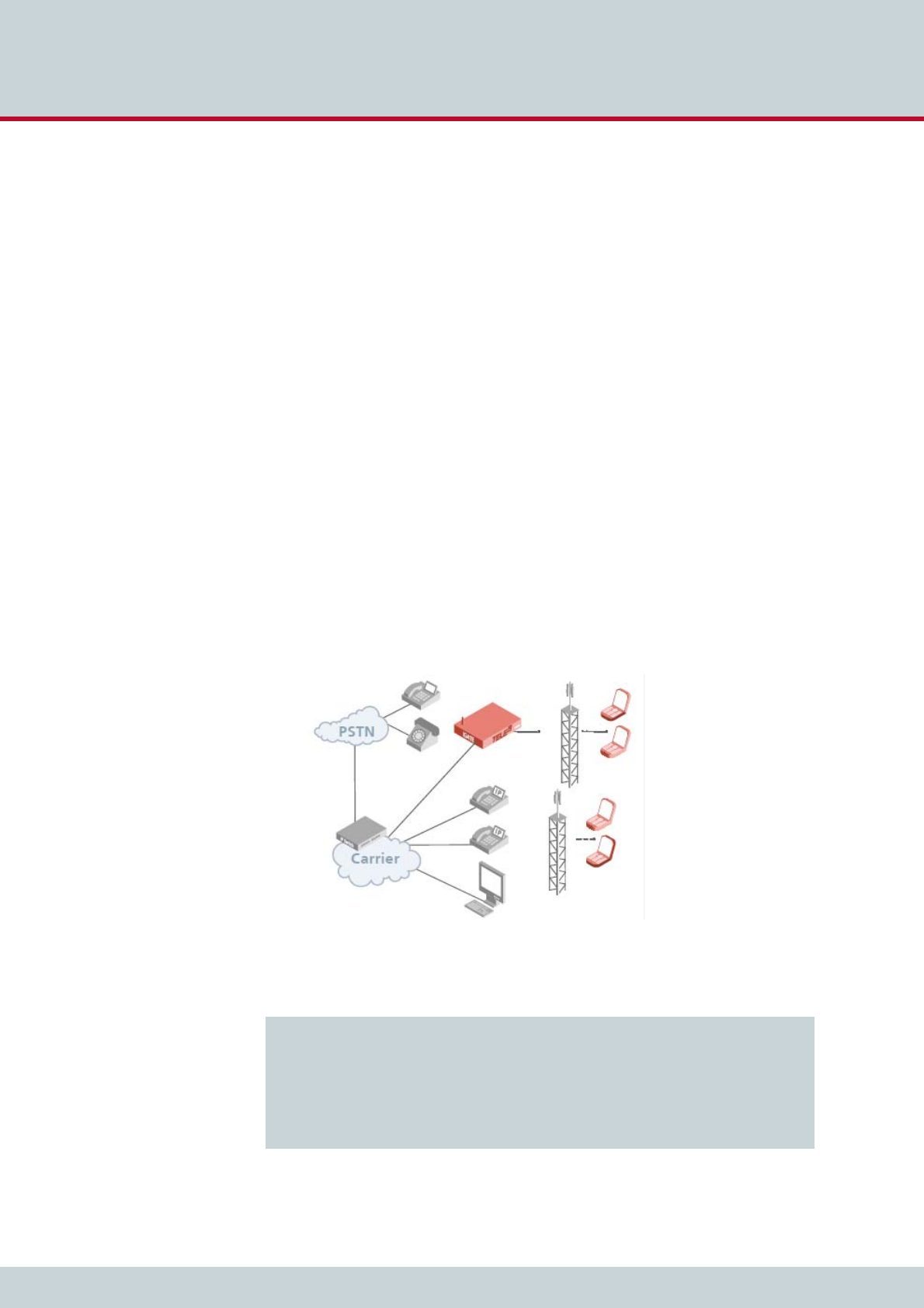
6 Routing examples
Page 84CELLX 16.2
6.1 CELLX integration in an H.323 carrier network
In the following example, an CELLX32 is integrated in a carrier network via H.323. The system
contains six SIM cards for each mobile channel, and the SIM 24 Carrier is used. All calls com-
ing from VoIP are routed to the mobile network. Four VoIP Modules with 16 media channels
each are attached in the system. H.323 is used as the signaling protocol and a gatekeeper is
used in the VoIP network. Because the gatekeeper assigns and authorizes the peer, only one
VoIP profile is necessary. Since the peers may use various compression algorithms, you can
define several if you so choose. The codec with the highest priority is G.729. If the peer does
not support it, G.726 32Bit/sec, G.711a, G.711u are also possible. Silence suppression is ac-
tive. The gatekeeper’s IP address is 192.168.0.10. This gatekeeper profile can handle up to
30 simultaneous VoIP calls. This value is dynamic and changes depending on the number of
active SIM cards. The CELLX’s alias is iGATE01. The prefix list is 01555 01556 01444 01445.
The gatekeeper’s alias is GK1 and no password is used. Calls with the prefixes 01555 and
01556 are sent to the carrier with the LAIN 26212 at controllers 0-15. Calls with the prefixes
01444 and 01445 are sent to the carrier with the LAIN 26313 (controllers 16-31). Digit col-
lection is activated, so that incoming calls with overlap dialing are not transmitted until the
number is complete or a wait timer (5 seconds) has run out. The NEXT parameter makes sure
that calls are distributed evenly to the individual mobile channels in the trunk group. The pa-
rameter CHADDR ensures that calls are not misrouted, since the controller definition changes
to the SIM card’s LAIN when a SIM card is mistakenly used for another mobile controller.
Problems can occur when SMS messages are also sent, as service center numbers are defini-
tively configured. The parameter LIMIT is set so that the system automatically switches to the
mobile controllers’ SIM cards when the active SIM card has been used for 3600 seconds. The
parameter CONTINUE makes sure the mobile channel switches to the first SIM card after the
limit has been reached on the last SIM card. The SIM card will not switch until currently active
calls have been disconnected.
Figure 6.1 CELLX integration with SIM card switching in an H.323 carrier network
Example 6.1 CELLX integration with SIM card switching in an H.323 carrier network (pabx.cfg)
Subscriber00 = TRANSPARENT ROUTER GSM[0000,00000,+00000,1,1,1,SIM24] CHADDR
LIMIT[3600,3600,3600,3600,3600,3600] CONTINUE ALARM NEXT
Subscriber01 = TRANSPARENT ROUTER GSM[0000,00000,+00000,1,1,1,SIM24] CHADDR
LIMIT[3600,3600,3600,3600,3600,3600] CONTINUE ALARM
....
Subscriber34 = TRANSPARENT ROUTER SWITCH CHMAX[16] ALARM
Subscriber35 = TRANSPARENT ROUTER SWITCH CHMAX[16] ALARM
ChargeUnitGenerate=1
LimitWODisc=ON

6 Routing examples
Page 85CELLX 16.2
6.2 CELLX as a second-generation LCR with VoIP
In the following example of a PBX connection, all mobile calls are terminated through the mo-
bile channels. Eight mobile channels form a group for one mobile network. One SIM card is
available on each mobile channel. Digit collection is activated, so that incoming calls with
overlap dialing are not transmitted until the number is complete or a wait timer (5 seconds)
has run out. The NEXT parameter makes sure that calls are distributed evenly to the individual
mobile channels in the trunk group. If all of a carrier’s SIM cards are busy, rerouting
(redirect3) via PSTN is automatically initiated. All international calls are terminated to VoIP
(40). The system contains two VoIP Modules, for a total of 32 media channels. The VoIP car-
rier profile DF and the SIP protocol are used. National calls are routed through the carrier with
the prefix 010xx. All other calls are sent to the PSTN unchanged. All calls from the PSTN or
from a VoIP carrier are sent directly to the NT controller, to which the PBX is attached. All in-
coming calls from the mobile networks are routed to the PBX’s central number (001). For the
Example 6.2 CELLX integration with SIM card switching in an H.323 carrier network (route.cfg)
[System]
DTMFWaitDial=5
MapAll01555=|2621201555<<17
MapAll01556=|2621201556<<17
MapAll01444=|2621301444<<17
MapAll01445=|2621301445<<17
[Voip:DF]
VoipDirection=In
VoipPeerAddress=10.0.0.0
VoipIpMask=0xffff0000
VoipSignalling=0
VoipCompression=g729 g72632 g711a g711u
VoipSilenceSuppression=Yes
VoipMaxChan=30
VoipTxM=2
VoipGk=GK1
[Gatekeeper:GK1]
RasPort=1719
OwnRasPort=1719
RasId=iGATE01
RasPrefix=01555 01556 01444 01445
GkId=GK
GkAdd=192.168.0.10
GkPwd=
GkTtl=300
GkMaxChan=30
GkDynMaxChan=Yes
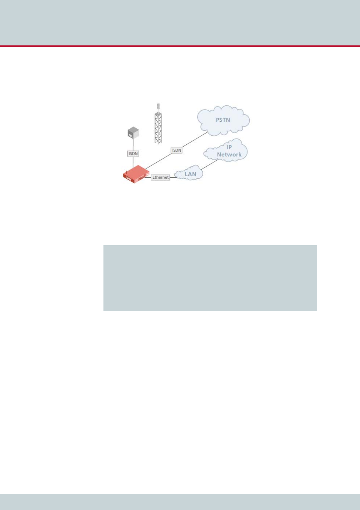
6 Routing examples
Page 86CELLX 16.2
VoIP profile DF, the system uses the registrar reg and registers with user@sip-carrier.de,
username user and password pwd. SIP UDP is used for signaling. A maximum of 30 media
channels with the G.729 codec can be used. The Peer is sip-carrier.de.
Figure 6.2 CELLX as a second-generation LCR with VoIP
Example 6.3 CELLX as a second-generation LCR with VoIP (pabx.cfg)
Subscriber00 = TRANSPARENT ROUTER GSM[0000,00000,+00000,1,1,1,SIM4] CHADDR ALARM
NEXT
Subscriber01 = TRANSPARENT ROUTER GSM[0000,00000,+00000,1,1,1,SIM4] CHADDR ALARM
....
Subscriber08 = TRANSPARENT ROUTER GSM[0000,00000,+00000,1,1,1,SIM4] CHADDR ALARM
NEXT
Subscriber09 = TRANSPARENT ROUTER GSM[0000,00000,+00000,1,1,1,SIM4] CHADDR ALARM
....
Subscriber16 = TRANSPARENT ROUTER ALARM
Subscriber17 = TRANSPARENT ROUTER ALARM
Subscriber18 = TRANSPARENT ROUTER SWITCH CHMAX[16] ALARM
Subscriber19 = TRANSPARENT ROUTER SWITCH CHMAX[16] ALARM

7 Mobile configuration options

7 Mobile configuration options
Page 88CELLX 16.2
7.1 Network-specific mobile routing
7.1.1 Routing decisions for calls to the mobile network
Internal routing decisions
Usually, routing decisions are made internally by the gateway. Calls to the mobile network
are routed based on the first digits of the called destination number (mobile network access
number) via a port or LAIN. The mapping looks like this:
MapAll<mobile network access number>=<port/LAIN><mobile network access
number>
In the example shown below, calls to the mobile network access number 0172 are routed via
port 20.
In the example below, calls to 0176 are routed via the LAIN 26227. To route via LAIN, the
keyword CHADDR needs to be added to the mobile port’s Subscriber configuration.
External routing decisions
In some cases, the routing decision needs to be made before the call arrives on the gateway.
This can be done by adding a technical prefix to the called number.
Each prefix represents a national mobile network. For instance 7777# could be the prefix to
route calls to the LAIN 26222, 8888# could route calls to the LAIN 26227.
If a call to the mobile network arrives on the gateway containing a technical prefix, this prefix
needs to be removed in the MapAll parameter and replaced by the port or LAIN. The config-
uration is:
MapAll<technical prefix>=<port/LAIN>
The mapping can be extended to contain the mobile network access number.
MapAll<technical prefix><mobile network access number>=<port/LAIN><mobile
network access number>
In the following example, calls containing the prefix 7777# are routed via port 20. Calls con-
taining the prefix 8888# are routed via port 21.
Example 7.1 Internal routing decision 1
MapAll0172=200172
Example 7.2 Internal routing decision 2
MapAll0176=262270176
Example 7.3 External routing 1
MapAll7777#=20
MapAll8888#=21

7 Mobile configuration options
Page 89CELLX 16.2
In the following example, calls which come in with the prefix 9999# and the mobile network
access number 0176 are routed via the LAIN 26227 to 0176.
7.1.2 Using the LAIN as the mobile port address
Use the LAIN as controller with the CHADDR parameter to prevent logging onto the wrong
SIM card. This will ensure that routing is network specific. The following example is based on
the German country code. One carrier’s LAIN is 26212 and the other carrier’s LAIN is 26213.
Example 7.4 External routing 2
MapAll9999#0176=262270176
Example 7.5 Using the LAIN as the mobile port address (pabx.cfg)
...
Controller00=20 GSM
Controller01=20 GSM
Controller02=20 GSM
Controller03=20 GSM
Controller04=20 GSM
Controller05=20 GSM
Controller06=20 GSM
Controller07=20 GSM
...
Subscriber00=TRANSPARENT ROUTER GSM[0000,00000,+49556,1,1,1,SIM4] CHADDR ALARM
Subscriber01=TRANSPARENT ROUTER GSM[0000,00000,+49556,1,1,1,SIM4] CHADDR ALARM
Subscriber02=TRANSPARENT ROUTER GSM[0000,00000,+49556,1,1,1,SIM4] CHADDR ALARM
Subscriber03=TRANSPARENT ROUTER GSM[0000,00000,+49556,1,1,1,SIM4] CHADDR ALARM
Subscriber04=TRANSPARENT ROUTER GSM[0000,00000,+49555,1,1,1,SIM4] CHADDR ALARM
Subscriber05=TRANSPARENT ROUTER GSM[0000,00000,+49555,1,1,1,SIM4] CHADDR ALARM
Subscriber06=TRANSPARENT ROUTER GSM[0000,00000,+49555,1,1,1,SIM4] CHADDR ALARM
Subscriber07=TRANSPARENT ROUTER GSM[0000,00000,+49555,1,1,1,SIM4] CHADDR ALARM
...
If you remove the keyword CHADDR from the pabx.cfg, you must restart the system. Control-
lers belonging to the same trunk group must have the same address. You must delete all rout-
ing entries based on port addresses when using the LAIN as controller.
Example 7.6 Using the LAIN as the mobile port address (route.cfg)
...
MapAll01555=2621201555
...
MapAll01556=2621301556
...
i
i

7 Mobile configuration options
Page 90CELLX 16.2
7.1.3 Fixed LAIN for a mobile port
Enter CHADDR[<addr>] to remove a mobile controller belonging to an LAIN group from the
standard routing process (for example for specific routes or only for SMS transmission). The
port address can be set to <addr>.
7.2 Incoming voice calls from mobile
Incoming mobile calls (service indicator 01 represents voice calls) can be routed to a specified
number. This enables each mobile controller to receive a unique identifier. It will then be
mapped to a number.
The mobile controllers can also have the same identifier, so that all voice calls (service indica-
tor 01) from controller 20 are sent to number 1111 at port 9. This number could, for example,
serve a call center.
7.3 Blocking ports
This function allows you to block a port, so that the corresponding mobile channel is omitted
from the distribution of calls. The function is particularly useful when mobile channels fail or
SIM cards cannot be immediately replaced.
To disable the port for outgoing calls enter the keyword CHINC[01,01] in the Subscriber
line and restart the system.
In the following example, port 04 is blocked for outgoing calls.
Example 7.7 Fixed LAIN for a mobile port
Subscriber05=TRANSPARENT ROUTER GSM[0000,00000,+49555,1,1,1,SIM4] CHADDR[444]
ALARM
MapAllSMS=444 DATA
The value entered for <addr> may not exceed 6 digits.
i
i
Example 7.8 Incoming voice calls from mobile 1
Restrict20=90123 01
Restrict21=91234 01
Example 7.9 Incoming voice calls from mobile 2
Restrict20=91111 01

7 Mobile configuration options
Page 91CELLX 16.2
To enable the port for outgoing calls, remove the entry and enter Activate Configuration.
7.4 Mobile user PBX callback
When the CELLX is implemented in a corporate network and connected to a PBX or between
a PBX and the outside line, the following configuration entry activates a feature, that uses a
mobile caller’s OAD to connect with the last PBX extension the caller unsuccessfully dialed.
DialBack=<hours>
The callback list is active for the number of hours entered.
DialBackMinutes=<minutes>
The callback is active for the number of minutes entered. After that time, the callback record
is deleted in the system.
DialBackStopOnConnect=<mode>
Deletes (On) the dialback record once a dialback call is connected. Off deactivates this behav-
ior.
DialBackCompare=<digits>
Shows the number of digits at the end of a phone number that are compared during dialback
handling. The default value is 10. Comparison of the end part of numbers is necessary when
the same number is displayed differently (when, for instance, one version includes the country
code, but the other doesn’t).
For calls coming from VoIP, add the following parameter to the used VoIP profile:
VoipOadIn=<name of profile used for callback>:
Enter the name of the VoIP profile that you use to call back the extension.
In the following example, the callback list is active for the previous five hours. The German
country code is used for the LAINs. All calls with the prefixes 1111 and 2222 are terminated
through the carrier with the LAIN 26212. Calls with the prefix 3333 are terminated through
the carrier with the LAIN 26213.
Example 7.10 Blocking ports
...
Subscriber04=TRANSPARENT ROUTER [0000,00000,<SMSC>,1,1,1,SIM4] CHADDR ALARM
CHINC[01,01]
...
Incoming calls are always possible. The status is not displayed in the GATE Manager.
i
i
Example 7.11 Mobile user PBX callback
DialBack=5
MapAll1111=262121111
MapAll2222=262122222
MapAll3333=262133333

7 Mobile configuration options
Page 92CELLX 16.2
7.5 Optional mobile quality parameters
The following parameters can be set for specific carriers if SIM cards for different mobile net-
works are used and different configurations must be set.
For all controllers without a LAIN, the following default setting applies: GSM=
Up to four additional carrier-specific entries may be set:
GSM1=<Lain1> ALFI[<val1/val0>]...
GSM2=<Lain2> ...
GSM3=<Lain3> ...
GSM4=<Lain4> ...
Up to four LAIN-specific configurations are possible. The user must enter the index (1 to 4).
The LAIN appears as the first entry behind the equal sign. Everything else follows.
The following table describes specific signaling and quality parameters for configuration of
the mobile interface.
Make sure that no Restrict entries are configured for these mobile controllers.
i
i
Bear in mind that for iGATE UMTS you must use the keyword UMTS= instead of GSM=!
The following syntax applies: UMTS1=<Lain1> ALFI[<val1/val0>]...
i
i
There is no automatic default behavior for this feature! All options must always be entered.
We recommend that you enter GSM= settings, as all controllers without a LAIN or with a de-
fault address use these options!
i
i
Table 7.1 Optional mobile parameters
GSM=... (for iGATE GSM) or UMTS= … (for iGATE UMTS)
Enter any of the following parameters after the equal sign for the following functions. Entries may
appear in any order, but all entries must appear in the same line and in double-digit notation as fol-
lows:
GSM=RSSI[10] STOP[18,08] ANNOUNCE[00,08] FAX[a2] ASR[20,35]
or
UMTS=RSSI[10] STOP[18,08] ANNOUNCE[00,08] FAX[a2] ASR[20,35]
ALERT[<sec>] Set this parameter to generate an alert signal in the D channel im-
mediately after the dial-end signal. If you enter optional square
brackets containing a number of seconds, the alert signal will oc-
cur when the number entered has passed following setup.

7 Mobile configuration options
Page 93CELLX 16.2
ANNOUNCE Set this parameter to define what happens when a recorded an-
nouncement is detected:
No ANNOUNCE entry (default)
A D-channel PROGRESS message stating Inband Information
Available will be generated
ANNOUNCE[<cause>]
The connection will be rejected with the defined ISDN cause
value. Do not enter the cause value ff!
ANNOUNCE[00,<sec>]
A timeout for voice detection is defined in seconds (default
value: 120 seconds). After the interval entered has passed, the
connection is torn down.
ANNOUNCE[ff]
The call will be connected as soon as an announcement is de-
tected.
FORWARD[<cause>] For GE864-QUAD modules only
The connection will be rejected with the defined ISDN cause value
when call forwarding is detected.
NOTE: The GSM network must support this feature for it to
work.
ASAL Announcement Stop during ALert: Set this parameter to release
calls if the GSM network sends an alert message, after which voice
is detected (for example the B-party rejects the call, which is then
forwarded to the B-party’s voicemail following the ring state).
The parameter ANNOUNCE[<cause>] must be set to activate this
parameter.
MINV[<count>] Minimum Voice detections: Parameter used with ASAL to define
the number of voice detections in a row before the call is released
(for example GSM-network background noise detected as voice).
The default value is 1, but 2 is recommended.
The parameters ANNOUNCE[<cause>] and ASAL must be set to
activate this parameter.
ASR[<limit>,
<calls>]
Allows you to change the default value (40 calls at 30% ASR). For
a definition of ASR, see Chapter 11.4.1 Generating and retrieving
CDRs.
CDC[<seconds>,
<count>]
Call duration check. When more than (<count>) connected calls in
a row occur with a call duration lower than <seconds>, an alarm
is generated and the port is restarted.
FAX[<cause>] This entry allows you to reject fax calls with the defined cause val-
ue.
RSSI[<limit>] Configure this parameter to set a limit for the reception field
strength. When the reception field strength falls below this limit,
the mobile channel will be blocked. If the field strength is above
the limit, the mobile channel will log on with the mobile carrier
again. The values used are 0 to 31, which represent the following
field strengths: -113dBm to -51 dBm. An error is generated in the
protocol log. The result must be divided by 2.
EXAMPLE: To define a field strength of -95 dBm, subtract -95
from-113 and divide the result by 2:
- 113dB - (-95dB) = -18dB / 2 = 9
Enter RSSI[9]
Table 7.1 Optional mobile parameters (continued)
GSM=... (for iGATE GSM) or UMTS= … (for iGATE UMTS)

7 Mobile configuration options
Page 94CELLX 16.2
STOP[<val1>,
<val2>]
This entry allows you to define a maximum number of connection
setups that always result in a recorded message (<val1>) without
an alert detection or call-connected signal. The second value
(<val2>) counts calls that connect immediately without an Alert
detection. The mobile port is blocked when the defined value is
reached and an entry is recorded in the log file (...Err: Voice). In this
way inactive SIM cards that are forwarded to a recording (with or
without a connect from the mobile carrier) can be detected and
blocked so that they are removed from the routing process. The
default status of this function is off.
NOCP When this option is configured and the call is from ISDN to GSM,
the Call Proceeding signaling message will be eliminated from sig-
naling. This may be necessary if the ISDN peer does not support
Call Proceeding. Bear in mind that the peer’s Setup Ack Timer is
usually set at 5 seconds, which means that an Alert must be gen-
erated as follows:
GSM=ALERT[5] (for iGATE GSM)
UMTS=ALERT[5] (for iGATE UMTS)
FMIN[xxx] FMAX[yyy] Sets the frequency range for ringtone detection (default 400-444
Hz).
EXAMPLE:
GSM=FMIN[400] FMAX[444] (for iGATE GSM)
UMTS=FMIN[400] FMAX[444] (for iGATE UMTS)
ALFI[<val1/val0>] GSM module GE864-QUAD only.
Switches the digital filter on (val=1) the Telit module to suppress
frequencies below 250 Hz per LAIN during alerting. (switch off
val=0)
Please use the parameter to enable alert-tone detection for dual
tone LAINs only (please see Chapter 7.5 Optional mobile quality
parameters).
VOICE[<sec>] The voice channel in the switching matrix is connected after <sec>
(default immediately). The voice channel is activated no later than
the point at which the call is connected.
WND9 Voice detection is activated in the GSM module if the GSM net-
work signals WND9 (voice). If this parameter is not set, voice de-
tection is activated immediately when the GSM call is initialized.
Module Q24xx only.
WND2A Generates Alert when WIND:2 is received.
Module Q24xx only.
WND2N Suppresses voice detection after WIND:2 is received.
Module Q24xx only.
MINA[<count>] Defines the number of alert tones that are required before an Alert
is detected.
Table 7.1 Optional mobile parameters (continued)
GSM=... (for iGATE GSM) or UMTS= … (for iGATE UMTS)

7 Mobile configuration options
Page 95CELLX 16.2
7.6 Deactivating mobile rerouting
Use the following entries in the pabx.cfg to deactivate rerouting for rejected calls.
REDIAL[<percent>,
<waitmin>,
<waitmax>,
<callingmin>,
<callingmax>,
<connectmin>,
<connectmax>,
<cfg>]
Repeats a call to the same B-party number as soon as the A party
hangs up. This parameter is useful for improving call statistics:
Percent: Percentage of calls (including alert only)
through the gateway that are redialed.
Waitmin: Minimum number of seconds the
gateway waits before redial.
Waitmax: Maximum number of seconds the
gateway waits before redial.
Callingmin: Minimum number of seconds the
gateway waits before call setup for redial. We
recommend no more than 8 seconds.
Callingmax: Maximum number of seconds the
gateway waits before call setup for redial. We
recommend no less than 15 seconds.
Connectmin: Minimum connect time (in seconds) if
call is connected.
Connectmax: Maximum connect time (in seconds)
before call is disconnected.
Cfg: Enter a value 1 – 4; valid for the 1= line to 4= line
for the iGATE GSM, or for the 1= line to 4= line for
the iGATE UMTS.
CPSA[0|1] When CPSA ist set to 0, the GSM port is forced to register the SIM
card to it’s home network, which is identified by the first 5 or 6
digits of the IMSI. This may result in a faster registration process.
CPSA[1] is the default value.
Table 7.1 Optional mobile parameters (continued)
GSM=... (for iGATE GSM) or UMTS= … (for iGATE UMTS)
Table 7.2 Deactivating mobile rerouting
Parameters
AllClassNext=<mode>
Enter AllClassNext=Off to deactivate rerouting for all rejected calls, regardless of the cause value
(default not configured).
NOTE: You cannot configure both AllClassNext and Class2Next simultaneously!
Class2Next=off
Enter Class2Next=Off to deactivate rerouting for calls rejected with a class 2 cause value (default
not configured).
NOTE: You cannot configure both AllClassNext and Class2Next simultaneously!
SelfNext=<int>
Set this parameter to reroute a failed call through the same port. <int> defines the number of call
attempts. Recommended values for <int> are 2 or 3. Bear in mind that this parameter must be
used in conjunction with the parameter AllClassNext=Off. Default not configured.
EXAMPLE:
SelfNext=3
AllClassesNext=Off

7 Mobile configuration options
Page 96CELLX 16.2
7.7 Setting autodial
When the following configuration is set, the gateway calls a defined list of phone numbers
automatically. Save the script in a text file with the extension *.ad.
The autodial process starts automatically when the script file has been copied to /boot or /
data. The file extension is renamed *.ax and is deleted when process has ended. A log file
*.al is generated in the course of the process. The file contains whether the call was success-
ful, the number called, the call duration for successful calls, and the cause value for failed
calls. To abort the process, simply delete the *.ax file.
The following settings are possible:
OPTION CALLDURATION: Enter an interval in seconds to define the length of the call.
OPTION CALLRETRIES: Enter the number of call attempts for each number.
OPTION CONFIGURATION: Refers to the number of the = configuration.
OPTION NOALARM: Set this option to suppress sending alarms when connected to a
vGATE.
D<sec>: Enter a value to define the duration for calls to this number.
P<sec>: Enter a value to define the pause between calls.
7.8 Disconnecting calls after ring
When the following parameter is configured, the call will be disconnected once the number
of configured seconds have passed after the mobile network has sent the first ring:
AWSTime=<sec>
7.9 Checking ports/mobile channels
Monitoring ASR for mobile ports
ASR monitoring of the last 40 calls occurs for all mobile ports. If the ASR (ASR2) is lower than
30 percent, an alarm is generated at the corresponding port and the port is blocked. The port
is then restarted and a corresponding entry appears in the protocol.log file (ASR). The port is
then unblocked.
The following entry in the pabx.cfg causes the mobile port to block automatically when this
error occurs three times in a row:
ASRBlock=On
When ASRBlock=Off is used, the port will be restarted and will remain open.
The following parameter in the pabx.cfg file allows you to change the default value (30%
for 40 calls):
GSM=ASR[<percent>,<number of calls>] (for iGATE GSM)
Example 7.12 Setting autodial
OPTION CALLDURATION 155-170
OPTION CALLRETRIES 2
OPTION CONFIGURATION 1
OPTION NOALARM
017222921 D10 P30
017222922 D10 P30
017222923 D10 P30
017222924 D10 P30

7 Mobile configuration options
Page 97CELLX 16.2
UMTS=ASR[<percent>,<number of calls>] (for iGATE UMTS)
7.10 Defining special characters for voice calls
In cases in which the called number includes special characters (for example * or #), it may be
necessary to define the call type used in the mobile network (command or voice call). Calls to
GSM or CDMA that begin with * or #, are sent as command calls by default. For voice calls
beginning with * or #, you must define the call type voice in the mapping entry with a > sign.
The routing entry will look like this:
MapAll<num>=<LAIN>><num>
Example 7.13 Monitoring ASR for mobile ports (iGATE GSM)
GSM=ASR[20,35]
Example 7.14 Monitoring ASR for mobile ports (iGATE UMTS)
UMTS=ASR[20,35]
Example 7.15 Defining special characters for voice calls
MapAll222=11111>*222

8 Signaling and routing features

8 Signaling and routing features
Page 99CELLX 16.2
8.1 Least cost routing
CELLXs are connected between the customer’s private branch exchange (PBX) and the public
telephone network (ISDN) and/or VoIP. The customer saves connection charges and can ef-
fortlessly and automatically connect to the corporate network as needed using one of six
routing methods:
Carrier selection
Dedicated lines
Direct line access with subaddressing
Direct line access with DTMF
Callback with subaddressing
Callback with DTMF
This manual contains information only on carrier selection. If you would like to configure any
other variation, please contact TELES or refer to the TELES Infrastructure Systems Manual Ver-
sion 4.5, Chapter 3.
Calls are routed transparently for the PBX and its users. CELLXs can generate charges and
route calls using alternate settings in case of network failures. The provider can access the
system via ISDN for routine maintenance and monitoring.
The following additional services are supported by this feature package:
Generation of charges
Time-controlled configuration
Alternative routing
8.1.1 Carrier selection
Carrier selection is currently one of the most commonly used routing methods supported by
the CELLX. In the CELLX, this routing process also includes direct calls into the mobile network
or through a VoIP network. That means the system is a full-fledged second generation LCR.
8.1.1.1 Routing entries
Use the MapAll command to route calls using Carrier Selection.
Use the following syntax for connections routed via the provider:
MapAll<AreaCode>=9<CarrierSelection><AreaCode>.
where <AreaCode> is the number or number range to be routed and <CarrierSelection>
is the access number required to reach the provider’s network.
For unrouted connections (placed via the public telephone network), use:
MapAll<AreaCode>=9<AreaCode>.
To block undesired carrier selection prefixes use:
MapAll<CarrierSelection>=&91;(Busy signal)
In the following example, calls to international destinations are terminated through the VoIP
interface. The profile names iG1 and iG2 in the routing entries refer to different VoIP carriers.
Calls to the mobile network (01555 and 01556) are routed directly through SIM cards for the

8 Signaling and routing features
Page 100CELLX 16.2
corresponding mobile carriers (LAIN 26212 and 26213). All other national long distance and
local calls are routed through an alternative carrier (01019). All calls from the PSTN to the PBX
are put through transparently.
8.1.2 Alternative routing settings
Alternative routing refers to the ability to establish connections using a different (alternative)
network in case of provider failure (for example all mobile controllers are in use). Alternative
routing ensures uninterrupted operation of the attached PBX. In such cases, connections are
often made via the public network using the Redirect command.
MapAll<num>=<port><num>
Redirect3<port><num>=<placeholder>
MapAll<placeholder>=<alt port><num>
Example 8.1 Carrier selection routing entries
MapAll001=40iG1:001
MapAll0044=40iG2:0044
...
MapAll01555=2621201555
MapAll01556=2621301556
...
MapAll01=90101901
MapAll02=90101902
...
MapAll09=90101909
MapAll1=9010191
MapAll2=9010192
...
MapAll9=9010199
Restrict9=10
Be sure to enter phone numbers in the routing file in ascending order.
i
i
Example 8.2 Alternative routing settings
MapAll01555=2621201555
Redirect32621201555=A
MapAllA=901555
8 Signaling and routing features
Page 101CELLX 16.2
8.1.3 Charge models
CELLXs can either generate charge information or transmit received charges from the public
or corporate networks to the attached PBX. Charge simulation is achieved using variables,
which ensure a great degree of flexibility for the implementation of many different charge
models including:
Charge units per time unit
Flat rate (initial charge without time interval)
Initial charge plus time interval
Initial charge plus time interval after delay
Time interval and/or flat rate plus received charges
Received charges only or no charge information
Initial toll-free period with retroactive charge generation afterwards
Price-per-minute (with whole second accuracy)
In this chapter, unit means that charge information is transmitted as a whole-numbered val-
ue, and currency means that the charge information is sent as a currency amount (for exam-
ple EUR 3.45). The charge impulse generation options can be set for each mapping by adding
charge-specific arguments to the MapAll commands as shown below. The use of each vari-
able is explained in Table 8.1.
MapAllsrc=dst mode time start/wait.
Any external charges can be added to the generated charges by adding 128 to the start value.
(The value range for the initial unit level is still set from 0 to 127). The maximum supported
number of units per connection is 32767 units.
Additional adjustments may be made to allow for the implementation of new charge models.
When charge information is sent as Currency, values can be expressed in thousandths
for greater precision in charge calculation.
For the internal Layer 3 protocols, charges can be specified to the third decimal place
(thousandth) using the /Value option (Example: /Value:1.056). In this fashion, charges
can be generated for units of currency requiring accuracy to the third decimal place or
Table 8.1 Charge variables
Variable Purpose
time Determines the length of each time interval (how long each unit lasts).
The value is entered in seconds and hundredths or thousandths of a
second (the maximum value accepted is 655.35 seconds, 65.535 if
thousandths are entered). If time is set to zero or not present no
charges are generated, external charge information is passed through
if received.
start Optional. Sets the initial unit level. Enter a value between 0 and 127
whole units. If you want to use a flat rate, set the desired number of
units here and set the wait to 255 to turn off the time interval.
wait Optional. Determines the delay after which charge generation begins.
Once this time has elapsed, charge impulses are sent in the interval de-
termined with time. Enter a value between 0 and 254 seconds. 255 de-
activates the charge pulse. In this case, the time variable is ignored.

8 Signaling and routing features
Page 102CELLX 16.2
for fractions such as tenths of a cent. This allows for greater flexibility in the
transmission of charges to terminal devices. In order to make use of this option,
connected devices must support “AOC-D Currency”. In the current version, this option
is only available for the DSS1 protocol.
A multiplication factor can be specified for received or generated charges.
During the charge generation process, each charge unit is multiplied by a preset factor.
This factor appears in the mapping entry after the time and start/wait variables
(MapAllsrc=dst mode time start/wait*factor).
Each unit, for example, can be converted to 12 cents. The following example illustrates
the use of this feature.
In this example, all received charge units are multiplied by 12 and passed on. If AOC-Currency
is set on the internal port, each unit appears as 12 cents. The multiplication factor is also used
to implement two new charge models:
If the factor value exceeds 128, this marks the use of an initial toll-free phase followed
by retroactive charge generation.
If the multiplication factor is set to 255, a “minute price” is used in place of the time
variable.
8.2 Online traffic monitor
The Online Traffic Monitor allows you to collect and monitor statistics and call detail records
(CDRs). The following functions are possible with this feature package:
ASR calculation
Generation of CDRs
Generation of online CDRs using e-mail
8.2.1 ASR calculation and resetting statistic values and counters
When these functions are configured in the pabx.cfg file, the following statistic values are
calculated for the entire system at a defined time and are copied into a file in the following
order:
Day and time of entry
System name
Number of connected calls followed by the number of total calls in parentheses
Number of minutes termintated
ASR1: ratio of total calls to connected calls disconnected by the A party
ASR(ext): external ASR for the traffic source
ASR(int): internal ASR for the CELLX
ACD: average call duration
The following example shows how the statistics appear in the file into which they are copied.
Example 8.3 Charge model
...
MapAll1=91 1 128/255*12
...
Example 8.4 Statistics file
26.10.04-00:00:00,iGATE810000: Calls: 19351 (29716) - Minutes: 46647 - ASR1:
65.12% - ASR(ext): 65.12% - ASR(int): 65.30% - ACD: 144.63s

8 Signaling and routing features
Page 103CELLX 16.2
Set the time using the following syntax: <hh:mm>. If ?? appears instead of a specified hour
(for example ??:mm), the ASR is written into the asr.log file once every hour.
You can set <day> to apply for days of the week or for one specific day of the month as fol-
lows:
Use a bitmask to set the weekdays on which the configuration applies here. The daymap ap-
pears in the following order: HoSaFrThWeTuMoSu. For example, enter 00000001 if the con-
figuration is to apply every Sunday.
To set the configuration to apply on one specific day every month, enter the day of the month
followed by a full stop. For example, enter 15. if the configuration is to apply on the 15th of
every month.
If the configuration is to apply every day, do not set <day>.
8.2.1.1 Saving and sending statistics
The statistics are copied into a specified file. This information can also be sent to an e-mail or
SMS recipient. The following syntax must be used:
StatisticTime=/data/asr.log <hh:mm> <day>
StatisticTime=/data/asr.log <hh:mm> <day> @<email address>
StatisticTime=/data/asr.log <hh:mm> <day> @SMS<mobile number>
In the following example, the system’s statistic values are saved every Wednesday into the file
asr.log and sent to an e-mail account.
In the following example, the system’s statistic values are saved at midnight on the first of
every month into the file asr.log and sent to an SMS recipient.
Do not configure both StatisticTimeReset and StatisticTime or StatisticTimeReset and Statis-
ticCounter together.
i
i
Example 8.5 Saving and sending statistics 1
StatisticTime=/data/asr.log 00:00 00001000 @info@teles.de
Example 8.6 Saving and sending statistics 2
StatisticTime=/data/asr.log 00:00 01. @SMS01234567890
Do not configure both StatisticTimeReset and StatisticTime together.
i
i

8 Signaling and routing features
Page 104CELLX 16.2
8.2.1.2 Saving statistics
The statistics are copied into a specified file and the counters (A-F) are reset. The following
syntax must be used:
StatisticTimeReset=/data/asr.log <hh:mm> <day>
In the following example, statistics will be saved every hour on the hour of every day and the
statistic counters will be reset to 0.
In the following example, the system’s statistic values are saved at noon on the 15th of every
month into the file asr.log.
8.2.1.3 Resetting statistic counters
The following setting in the pabx.cfg resets the statistic counters and unblocks the controller
group. The following syntax must be used:
ResetCounter=<port> <hh:mm> <day> or
ResetCounter=<LAIN> <hh:mm> <day>
Up to five entries for as many groups and/or times are possible. Bear in mind that StatisticTim-
eReset must be inactive to avoid repetition. The mapping to a LAIN requires that in the
pabx.cfg file, the CHADDR parameter is added to the Subscriber line, to change the con-
troller definition to the SIM card’s LAIN.
In the following example the counters will reset for LAIN group 26211 every day at midnight,
for the group 26212 only once on the first day of the month, and for 26213 each Saturday
at 8:00pm.
Example 8.7 Saving statistics 1
StatisticTimeReset=/data/asr.log ??:00
Example 8.8 Saving statistics 2
StatisticTimeReset=/data/asr.log 12:00 15.
Do not configure both StatisticTimeReset and StatisticTime or StatisticTimeReset
and StatisticCounter together.
i
i
Example 8.9 Resetting statistic counters
ResetCounter = 26211 00:00 11111111
ResetCounter = 26212 00:00 01.
ResetCounter = 26213 20:00 01000000

8 Signaling and routing features
Page 105CELLX 16.2
8.2.2 Generating and retrieving CDRs
With the Log and failedlog commands, you save CDRs and unconnected calls in the CELLX.
For these parameters (Log and failedlog), a folder and file name must always be specified
after the equal sign. The function is not active (no data is recorded) until a file name is spec-
ified.
The service indicator listed in the call log and missed calls list describes the type of connection
as a four digit hexadecimal number. The coding is conducted according to the 1TR6 standard.
A few frequently used values are listed below.
Do not configure both StatisticTimeReset and StatisticCounter together.
i
i
Example 8.10 Generating and retrieving CDRs
Log=/data/cdr.log
failedlog=/data/failed.log
With recording of files, system maintenance increases. You have to be sure to download or
delete files and ensure that there is enough disk space left on the hard drive.
i
i
Table 8.2 Service indicator list
Service indicator Description
0101 ISDN-telephony 3.1 kHz
0102 analog telephony
0103 ISDN-telephony 7 kHz
0200 Fax group 2
0202 Fax group 3
0203 Data via modem
0400 Telefax group 4
0500 SMS or BTX (64 kbps)
0700 Data transfer 64 kbps
1001 Video telephone – audio 3.1 kHz
1002 Video telephone – audio 7 kHz
1003 Video telephone – video

8 Signaling and routing features
Page 106CELLX 16.2
For detailed information on how to automatically divide the files (for example on a daily basis),
please refer to the Chapter 5.2.1.2 Log files.
8.2.2.1 Call log
The following entry in the pabx.cfg configuration file activates the capability to generate
CDRs in the CELLX:
Log=/data/cdr.log
The cdr.log file is stored in the data directory. New entries are always added to the end of the
file. The file is open only during editing.
Each line represents an outgoing call with the following information separated by commas:
Table 8.3 Call log entries
Column Description
0Version
1Start time (format DD.MM.YY-hh.mm.ss)
2End time (format DD.MM.YY-hh.mm.ss)
3Source. The following format applies: [node number:automatically set internal
channel number]
4Destination. The following format applies: [node number:automatically set in-
ternal channel number]
5IMSI
6IP logging signaling: RTP
7Audio codec used
8Frame size
9Service indicator (please see Chapter 8.2.2 Generating and retrieving CDRs)
10 Call duration
11 Cause values
12 Charge from the public line (in units)
13 Charge generated from the system (in units)
14 Cell ID
15 RSSI

8 Signaling and routing features
Page 107CELLX 16.2
Sample log file
The example below shows a sample log file.
Differentiating between ports in the same trunk group
To differentiate between ports with the same number in the CDRs, a specific node number
must be defined. You can expand the subscriber configuration line with the keyword
NODE[<num>] for this purpose. <num> can be a string of between 1 and 15 characters:
Subscriber<xx>=... NODE[<num>]
In the below formula, <num> consists of a four-digit number that is included in the CDR.
Example 8.11 Sample log file
V1,25.11.09-10:16:20,25.11.09-
10:16:27,[0000:01]9,[0006:01]111,123456789123451,,,,0102,7,1f,0,,3663,10
V1,25.11.09-10:35:16,25.11.09-
10:35:26,[0000:01]9,[0004:01]111,123456789123452,,,,0102,10,1f,0,3,38922,14
V1,25.11.09-10:38:30,25.11.09-
10:38:41,[0000:01]9,[0004:01]111,123456789123453,,,,0102,11,90,0,3,38922,14
Example 8.12 Differentiating between ports in the same trunk group (CDR entry)
V1,25.11.09-10:16:20,25.11.09-
10:16:27,[0000:01]9,[0006:01]111,
12345678912345
1,,,,0102,7,1f,0,,3663,10

8 Signaling and routing features
Page 108CELLX 16.2
The following example shows the pabx.cfg configuration file changed according to the for-
mula.
Differentiating between SIM cards
The CDR can contain the IMSI (International Mobile Subscriber Identity), which identifies each
SIM card used.
Example 8.13 Differentiating between ports in the same trunk group (pabx.cfg entry)
...
Subscriber00=TRANSPARENT ROUTER GSM[0000,00000,<SMSC>,1,1,1,SIM24] CHADDR ALARM
NEXT NODE[0001]
Subscriber01=TRANSPARENT ROUTER GSM[0000,00000,<SMSC>,1,1,1,SIM24] CHADDR ALARM
NEXT NODE[0002]
Subscriber02=TRANSPARENT ROUTER GSM[0000,00000,<SMSC>,1,1,1,SIM24] CHADDR ALARM
NEXT NODE[0003]
Subscriber03=TRANSPARENT ROUTER GSM[0000,00000,<SMSC>,1,1,1,SIM24] CHADDR ALARM
NEXT NODE[0004]
Subscriber04=TRANSPARENT ROUTER GSM[0000,00000,<SMSC>,1,1,1,SIM24] CHADDR ALARM
NEXT NODE[0005]
Subscriber05=TRANSPARENT ROUTER GSM[0000,00000,<SMSC>,1,1,1,SIM24] CHADDR ALARM
NEXT NODE[0006]
Subscriber06=TRANSPARENT ROUTER GSM[0000,00000,<SMSC>,1,1,1,SIM24] CHADDR ALARM
NEXT NODE[0007]
Subscriber07=TRANSPARENT ROUTER GSM[0000,00000,<SMSC>,1,1,1,SIM24] CHADDR ALARM
NEXT NODE[0008]
Subscriber08=TRANSPARENT ROUTER GSM[0000,00000,<SMSC>,1,1,1,SIM24] CHADDR ALARM
NEXT NODE[0009]
Subscriber09=TRANSPARENT ROUTER GSM[0000,00000,<SMSC>,1,1,1,SIM24] CHADDR ALARM
NEXT NODE[0010]
Subscriber10=TRANSPARENT ROUTER GSM[0000,00000,<SMSC>,1,1,1,SIM24] CHADDR ALARM
NEXT NODE[0011]
Subscriber11=TRANSPARENT ROUTER GSM[0000,00000,<SMSC>,1,1,1,SIM24] CHADDR ALARM
NEXT NODE[0012]
Subscriber12=TRANSPARENT ROUTER GSM[0000,00000,<SMSC>,1,1,1,SIM24] CHADDR ALARM
NEXT NODE[0013]
Subscriber13=TRANSPARENT ROUTER GSM[0000,00000,<SMSC>,1,1,1,SIM24] CHADDR ALARM
NEXT NODE[0014]
Subscriber14=TRANSPARENT ROUTER GSM[0000,00000,<SMSC>,1,1,1,SIM24] CHADDR ALARM
NEXT NODE[0015]
Subscriber15=TRANSPARENT ROUTER GSM[0000,00000,<SMSC>,1,1,1,SIM24] CHADDR ALARM
NEXT NODE[0016]
...
Example 8.14 Differentiating between SIM cards (CDR entry)
V1,25.11.09-10:35:16,25.11.09-
10:35:26,[0000:01]9,[0004:01]111,123456789123451,,,,0102,10,1f,0,3,38922,14

8 Signaling and routing features
Page 109CELLX 16.2
The following example shows the pabx.cfg configuration file changed according to the for-
mula.
Activating peer data for VoIP calls
To generate a VoIP-call CDR entry that includes IP addresses for the remote device’s signaling
and voice data, audio codec and frame size, the entry VoipIpLogging=Yes must be included
in the VoIP profile. If the entry also contains the mobile controller’s IMSI, it will appear before
the IP addresses.
Example 8.15 Differentiating between SIM cards (pabx.cfg entry)
...
Subscriber00=TRANSPARENT ROUTER GSM[0000,00000,<SMSC>,1,1,1,IMSI,SIM24] CHADDR
ALARM NEXT
Subscriber01=TRANSPARENT ROUTER GSM[0000,00000,<SMSC>,1,1,1,IMSI,SIM24] CHADDR
ALARM NEXT
Subscriber02=TRANSPARENT ROUTER GSM[0000,00000,<SMSC>,1,1,1,IMSI,SIM24] CHADDR
ALARM NEXT
Subscriber03=TRANSPARENT ROUTER GSM[0000,00000,<SMSC>,1,1,1,IMSI,SIM24] CHADDR
ALARM NEXT
Subscriber04=TRANSPARENT ROUTER GSM[0000,00000,<SMSC>,1,1,1,IMSI,SIM24] CHADDR
ALARM NEXT
Subscriber05=TRANSPARENT ROUTER GSM[0000,00000,<SMSC>,1,1,1,IMSI,SIM24] CHADDR
ALARM NEXT
Subscriber06=TRANSPARENT ROUTER GSM[0000,00000,<SMSC>,1,1,1,IMSI,SIM24] CHADDR
ALARM NEXT
Subscriber07=TRANSPARENT ROUTER GSM[0000,00000,<SMSC>,1,1,1,IMSI,SIM24] CHADDR
ALARM NEXT
Subscriber08=TRANSPARENT ROUTER GSM[0000,00000,<SMSC>,1,1,1,IMSI,SIM24] CHADDR
ALARM NEXT
Subscriber09=TRANSPARENT ROUTER GSM[0000,00000,<SMSC>,1,1,1,IMSI,SIM24] CHADDR
ALARM NEXT
Subscriber10=TRANSPARENT ROUTER GSM[0000,00000,<SMSC>,1,1,1,IMSI,SIM24] CHADDR
ALARM NEXT
Subscriber11=TRANSPARENT ROUTER GSM[0000,00000,<SMSC>,1,1,1,IMSI,SIM24] CHADDR
ALARM NEXT
Subscriber12=TRANSPARENT ROUTER GSM[0000,00000,<SMSC>,1,1,1,IMSI,SIM24] CHADDR
ALARM NEXT
Subscriber13=TRANSPARENT ROUTER GSM[0000,00000,<SMSC>,1,1,1,IMSI,SIM24] CHADDR
ALARM NEXT
Subscriber14=TRANSPARENT ROUTER GSM[0000,00000,<SMSC>,1,1,1,IMSI,SIM24] CHADDR
ALARM NEXT
...
If you remove the keyword IMSI from the pabx.cfg, you must restart the system.
i
i

8 Signaling and routing features
Page 110CELLX 16.2
The following entry shows the route.cfg configuration file changed according to the for-
mula.
The following CDR entry includes IP addresses for signaling and voice data, audio codec and
frame size.
CDRs for callback and two stage calls
In the case of CDR entries for Two stage dialing/Callback calls, the beginning and ending
times for the first call leg is always used as the call time. The call time in seconds appears first
for the first leg, followed by a slash and the connection time for the second leg.
Specific cause values
The CELLX will generate cause values that represent an event, such as exceeding a defined
limit.
Example 8.16 Activating peer data for VoIP calls (route.cfg entry)
[Voip:DF]
VoipDirection=IO
VoipPeerAddress=192.168.0.2
VoipIpMask=0xffffffff
VoipCompression=g729 t38
VoipMaxChan=30
VoipSilenceSuppression=Yes
VoipSignalling=0
VoipTxM=4
VoipIPLogging=Yes
Example 8.17 Activating peer data for VoIP calls (CDR entry)
V1,24.11.09-16:52:20,24.11.09-
16:52:22,[0008:01]401419,[0006:01]IN777,
123456789123451
,172.20.25.103:172.20.25.103,G711a,20,0101,2,10,0,,341
93,11
Example 8.18 CDR entry for callback and two stage calls
V1,24.11.09-17:15:29,24.11.09-
17:15:57,[0002:01]CB,[0008:01]DLA,,172.20.25.103:172.20.25.103,G711a,20,0102,28/
3,90,0,,,
Table 8.4 Specific cause values
Cause value Description
0a One of the following limits has been reached:
Unit limit defined in the port’s subscriber line
0b Maximum call duration assigned via vGATE has been reached.
0c Maximum call duration based on mapping entry settings has been reached.

8 Signaling and routing features
Page 111CELLX 16.2
8.2.2.2 Missed calls list
All incoming calls that are not connected can be recorded in a list to facilitate return calls.
Recording is activated using the failedlog=<name> entry in the pabx.cfg. Specify a file
name, for example failedlog=failed.log. Once this setting is made, recording begins at once.
Each line represents an unaccepted incoming call with the following information separated
by commas.
0d Maximum number of minutes per SIM assignment via vGATE has been
reached.
10, 1f Normal call termination (disconnected by calling party).
To avoid sending these values as the reason for call teardown, translate the cause values to
standard values Chapter 8.14 Changing cause values.
Table 8.4 Specific cause values
Cause value Description
i
i
Table 8.5 Failed log entries
Column Description
0Version
1Start time (format DD.MM.YY-hh.mm.ss)
2Source. The following format applies: [node number:automatically set internal
channel number]
3Destination. The following format applies: [node number:automatically set inter-
nal channel number]
4IMSI
5IP logging signaling: RTP
6Audio codec used
7Frame size
8Service indicator (please see Chapter 8.2.2 Generating and retrieving CDRs)
9Cause values
10 Call duration (if the call does not result in an Alerting, the entry will be -1)
11 Number of call attempts
12 Cell ID
13 RSSI

8 Signaling and routing features
Page 112CELLX 16.2
The reason the connection could not be established is specified using DSS1 codes:
91 – (user busy)
ff – call not answered (disconnected by calling party)
When callback with DTMF is configured and no connection is established to the B subscriber,
an entry recording the A subscriber’s connection time is generated in the failed.log file.
The CDR contains the IP addresses for signaling and voice data. The first IP address is the sig-
naling address and the second one is the RTP address.The IMSI is written behind the IP ad-
dresses if the keyword IMSI is defined in the pabx.cfg.
In the case of missed-call entries for Two stage dialing/Callback calls, dur is the connection
time for the first leg.
8.2.2.3 Sending CDRs via e-mail
With an appropriate configuration, you can send corresponding CDRs of outgoing and in-
coming calls as e-mail. Bear in mind that the mail server must be configured in the [Mail] sec-
tion of the pabx.cfg, as described in Chapter 5.2.2 SMTP-client configuration. The sender is
given as cdr and the system’s name appears in the subject box. The text box contains the CDR
Example 8.19 Failed.log file
V1,24.11.09-16:13:08,[0006:01]IN,[0008:01]GSM,123456789123456,,,,0101,92,-
1,1,34193,9
V1,24.11.09-16:33:34,[0006:01]IN,[0008:01]GSM,123456789123456,,,,0101,92,-
1,1,34193,12
V1,24.11.09-16:35:19,[0006:01]IN,[0008:01]GSM,123456789123456,,,,0101,92,-
1,1,34193,11
V1,24.11.09-16:35:59,[0006:01]IN,[0008:01]GSM,123456789123456,,,,0101,92,-
1,1,34193,11
V1,24.11.09-16:37:29,[0006:01]IN,[0008:01]GSM,123456789123456,,,,0101,92,-
1,1,34193,11
V1,24.11.09-
16:39:17,[0006:01]IN,[0008:01]GSM,123456789123456,,,,0101,ff,7,1,34193,11
Example 8.20 Failed.log entry 1
V1,24.11.09-
16:39:17,[0006:01]IN,[0008:01]GSM,123456789123456,,,,0101,ff,7,1,34193,11
Example 8.21 Failed.log entry 2
V1,24.11.09-16:52:20,24.11.09-
16:52:22,[0008:01]401419,[0006:01]IN777,262032441017556,172.20.25.103:172.20.25.
103,G711a,20,0101,2,10,0,,34193,11
Example 8.22 Failed.log entry 3
V1,25.11.09-14:11:10,[0002:01]CB,DLA,,,,,0102,11,14,1,,

8 Signaling and routing features
Page 113CELLX 16.2
information according to the format for the entry in Log=/data/cdr.log @<account> @<do-
main>. A space must appear between cdr.log and @<account>; @<domain> is optional. You
can also send CDR entries via e-mail to an e-mail recipient.
Enter an @ sign to send each CDR entry as e-mail:
Log=/data/cdr.log @<e-mail account>@<domain>
If you enter a ! the entire cdr.log will be sent as an e-mail attachment:
Log=/data/cdr.log !<e-mail account>@<domain>
8.3 Ported number screening
Ported number screening is a very useful functionality to avoid high routing costs for numbers
that have been ported to another network operator.
Number portabilty refers to the ability to transfer either an existing fixed-line or mobile tele-
phone number to another network operator. This way telecommunications subscribers can
change operators without having to change their telephone numbers. Routing ported num-
bers, however, can become very cost intensive due to differences in tariffs.
With ported number screening, an external database is queried to find out if a number has
been ported. Either use the iMNP for querying the external database or query the database
directly. The iMNP is a proxy that remembers the database information for a defined period
of time and renews the query to the external database only after that period has passed. Since
every query to the external database costs money, the iMNP helps to reduce querying costs.
The qery result is used in a routing to route the call via the right network operator.
To implement ported number screening, make sure to meet the system requirements which
are:
An active license for number portability.
An iMNP server or another appropriate server.
Also ensure to adjust your configuration:
To connect to the number portability database, you must set the entries described in
Chapter 5.2.3 Number portability settings.
Configure your route.cfg file to activate ported number screening:
DTMFWaitDial=<sec>
Set the time that the gateway waits for additional digits.
MapAll<num>=|$<prefix><num><<<count>
Enable digit collection (pipe symbol) and collect up to the number of digits that is
specified under count. Add the dollar sign to search the routing table again. Prefix the
number with a freely chosen prefix to prepare it for sending to the database.
MapAll<prefix>=|D@<num><<01
Send the prefixed number to the database. Make sure that the prefix used here matches
the above prefix.
MapAllQN<query result>=<controller>
Map the query result to the respective controller. The query result consists of the LAIN
and the number including the country code. Do not forget to also configure routings
for numbers that haven’t been found in the database or that do not exist and also
provide a routing when the server does not respond in a defined period of time.
In the following example, 14 digits are collected (11 digits plus $ph) and a maximum time of
5 seconds is waited for each digit. Every incoming call with a leading digit of 0 results in an
iMNP query. The SIM card’s LAIN is used instead of controller numbers. All numbers that
come back from the iMNP with the LAIN for Carrier_1 (26211) are then routed through

8 Signaling and routing features
Page 114CELLX 16.2
Carrier_1’s SIM card. The same applies for Carrier_2 (26212), Carrier_3 (26213) and Carrier_4
(26214). Numbers that the iMNP sends back as non-existing (00000) are rejected. Numbers
that may exist but are not found in the database (99999) are routed as they come in (normal).
If the iMNP does not respond within two seconds (D@0), the call is routed as it comes in,
whether it is ported or not.
8.4 Digit collection (enblock/overlap receiving)
This function makes it possible to collect up to 24 digits and transmit calls when a specific
number of digits has been dialed. The entire call number is required for the call to be set up
with a mobile phone or the mobile gateway. Since most numbers have a uniform number of
digits, the mobile gateway can collect digits when calls enter the gateway in overlap mode.
Digit collection occurs through the following mapping command:
MapAll<direct>=|<num><<<digits>
The | (pipe) signifies that the following digits will be collected before they are transmitted, and
<digits> is the total number of the port digits and the digits of the called party number. This
figure can range between 00 and 24 and must be entered in double digits. The parameter
DTMFWaitDial defines the number of seconds the system waits between the individual digits
(default 5). Please bear in mind that you can configure a maximum of 11 digits in the first part
of the command and 19 (including a special character, for example #) in the second. The call
will be forwarded as soon as the specified number of digits has been dialed or a time-out limit
has been reached.
Example 8.23 Ported number screening
DTMFWaitDial=5
MapAll0=|$ph0<<14
MapAllph=|D@0<<01
MapAllQN26211=26211
MapAllQN26212=26212
MapAllQN26213=26213
MapAllQN26214=26214
MapAllQN00000=&81
MapAllQN99999=$normal
MapAllD@0=$normal1
; not in Database
;Carrier_1
MapAllnormal0151=262110151
MapAllnormal0160=262110160
MapAllnormal0170=262110170
MapAllnormal0171=262110171
MapAllnormal0175=262110175
;Carrier_2
MapAllnormal0152=262120152
MapAllnormal0162=262120162
MapAllnormal0172=262120172
MapAllnormal0173=262120173
MapAllnormal0174=262120174
;Carrier_3
MapAllnormal0155=262130155
MapAllnormal0163=262130163
MapAllnormal0177=262130177
MapAllnormal0178=262130178
;Carrier_4
MapAllnormal0159=262140159
MapAllnormal0176=262140176
MapAllnormal0179=262140179

8 Signaling and routing features
Page 115CELLX 16.2
The following example shows a call with the prefix 01555. The | (pipe) signifies that the fol-
lowing digits will be collected before they are transmitted. The 14 at the end is the sum of
the port digits and the digits of the called party number (for example |#20=3,
01555899666=11, 3+11=14).
8.5 Rejecting data calls and specified numbers
This chapter describes the configuration options for exclusion of data calls, prefixes, or call
numbers from the routing process.
8.5.1 Blacklist routing
The system will reject all calls directly if the MapAll entry contains the keyword & followed by
the two-digit cause value (see ETS 300 102-1).
MapAll<direct>=&<cause>
In the following example, all calls to the number 004915551234 and all service calls with the
prefix 0180 are rejected with a busy signal. All other calls are sent to the VoIP profile DF.
8.5.2 Whitelist routing
The following entries enable exclusion of specific OADs or trunk groups:
Restrict<ns>=<pl>
MapAll<pl>=&<cause>
Example 8.24 Digit collection
...
MapAll01555=|#2001555<<14
...
DTMFWaitDial=5
...
A maximum of 5000 MapAll entries per time zone can be defined. For more than 5000 en-
tries, please use the iMNP.
i
i
Example 8.25 Blacklist routing
MapAll015551234=&91
MapAll004915551234=&91
MapAll0180=&91
MapAll0=40DF:0
...
MapAll9=40DF:9

8 Signaling and routing features
Page 116CELLX 16.2
NS refers to the internal controller number and the call’s origination address.
In the following example, the numbers 12345 and 12346 connected to the PBX at port 10
cannot make any international calls. All national calls are sent to the VoIP profile DF and all
local calls are sent to the PSTN.
In the following example, all incoming calls from the mobile port trunk groups 26212 and
26213 are rejected with a busy signal.
8.5.3 Rejecting calls with ISDN bearer capability data
ISDN data calls can be handled differently from voice calls depending on the configuration of
the call types DATA or VOICE. This setting is especially interesting for VoIP or GSM calls.
MapAll<direct>=&<cause> <mode>
A maximum of 1000 Restrict entries per time zone can be defined.
i
i
Example 8.26 Whitelist routing 1
Restrict1012346=int
MapAllint00=&91
MapAllint0=40DF:0
MapAllint1=91
...
MapAllint9=90
Example 8.27 Whitelist routing 2
Restrict26212=not
Restrict26213=not
MapAllnot=&91
Analog modm connections are not included in this configuration, as they generally do not
have a specified bearer capability.
i
i

8 Signaling and routing features
Page 117CELLX 16.2
In the following example, all ISDN data calls are rejected with the cause value AA (switching
equipment congestion). All calls with the prefix 0170 are routed to the mobile trunk group
26211 and all other calls are routed through VoIP.
8.5.4 Specific routing of data calls via VoIP
In the ISDN network, data calls have a special service type. When an ISDN PBX is connected
to a VoIP network, it must continue to work without any problems (for example PBX remote
maintenance calls or ISDN terminal adapter). In the case of VoIP, a specific RTP payload type
is used: trp, ccd or gnx64.
In the following example, two VoIP profiles are configured, so that all calls are routed, regard-
less of whether they are data calls or voice over IP calls. The first one is for outgoing voice calls
and all calls from VoIP to ISDN. The second profile is exclusively for outgoing data calls, so
that signaling consists solely of clear mode in SDP.
8.6 CLIP and CLIR
8.6.1 Routing CLIP and CLIR calls
This function allows you to route calls with Calling Line Identification Presentation (CLIP) dif-
ferently from calls with Calling Line Identification Restriction (CLIR). For example, all CLIP calls
can be rejected, so that only calls that do not present the calling number or calls without a
calling party number (for example analog) are transmitted through the CELLX.
Example 8.28 Rejecting calls with ISDN bearer capability data
MapAll0=&aa DATA
...
MapAll9=&aa DATA
...
MapAll0170=262110170
MapAll0=40DF:0
...
MapAll9=40DF:9
Example 8.29
MapAll0=40DATA:0 DATA
...
MapAll9=40DATA:9 DATA
MapAll0=|40DF:0<<24
...
MapAll9=|40DF:9<<24
Restrict40=In
MapAllIn=10
[Voip:DF]
VoipDirection=IO
...
VoipCompression=g711a g729 trp t38
...
[Voip:DATA]
VoipDirection=Out
...
VoipCompression=trp
VoipECE=No
...

8 Signaling and routing features
Page 118CELLX 16.2
Use the following configuration to define the various routing methods.
InsertCLIR=On activates this mode. 01 is the service indicator for telephony (analog and ISDN)
and is used to differentiate these calls from remote administration calls. Restrict9=OK 01
means that all telephony calls without a calling number are put through. Restrict|9=OK 01
means that all CLIR telephony calls are put through. Restrict90=FAIL 01 means that all CLIP
telephony calls are rejected with No Channel Available as rejection cause when they are
mapped to MapInFAIL=&aa.
8.6.2 Routing calls without CLIR
Use this function to bypass CLIR for calls through the defined mobile port. The following con-
figuration in pabx.cfg activates this function.
8.6.2.1 Setting CLIR
Setting a hash (#) in front of a call number makes it possible to suppress the presentation of
the origination number of calls regardless of how the call comes into the system.
The following syntax is used: MapAll<num>=#<port><num>.
The following example shows an appropriate configuration. With this entry, all calls begin-
ning with 00491555 are sent to the port with the address 22 and the presentation of the
number is restricted.
Example 8.30 Routing CLIP and CLIR calls
...
InsertCLIR=On
...
Restrict9=OK 01
Restrict|9=OK 01
Restrict90=FAIL 01
...
MapInOK00491555=2200491555
MapInFAIL=&aa
...
Example 8.31 Routing calls without CLIR
Subscriber<xx>=...GSM[...,!CLIR]...
When this function is configured, the SIM’s telephone number (and not originating telephone)
is always transmitted to the B subscriber.
i
i
Example 8.32 Setting CLIR
MapAll00491555=#2200491555

8 Signaling and routing features
Page 119CELLX 16.2
8.6.2.2 Setting CLIP
Setting an exclamation point (!) in front of a call number makes it possible to force the pre-
sentation of the origination number of calls regardless of how the call comes into the system.
The following syntax is used: MapAll<num>=!<port><num>
The following example shows an appropriate configuration. With this entry, all calls begin-
ning with 004930 are sent to the port with the address 9 and the presentation of the origi-
nation number is allowed.
8.7 Conversion of call numbers
The conversion of call numbers makes it possible, for example, to implement number porta-
bility or to redirect calls when the user can be reached at another number. In the following
mapping command, the call number 015550123456 is changed to 015559876543 and sent
to the mobile channel (MapAll...=20..)
The following example presents an alternative, in which the routing file is searched through
again after conversion of the call number to determine the route for the prefix 01555. Please
bear in mind that you can configure a maximum of 1499 mapping entries with no more than
11 digits in the first part of the command and 19 in the second.
8.8 Overwriting OAD
In some cases where the OAD is not transmitted or shall for other reasons be overwritten, the
following parameter can be used to send another OAD:
Restrict<port>=<OAD to be sent> 15 or
Restrict<port><original OAD>=<OAD to be sent> 15
For PRI ports only: extend this parameter by a text in quotation marks to transmit a display
info element in a PRI or SIP call. If supported by the receiving telephone, the content of the
display field is displayed in addition or instead of the OAD.
Restrict<port>=<OAD to be sent> 15 “display field“ or
Restrict<port><original OAD>=<OAD to be sent> 15 “display field“
Example 8.33 Setting CLIP
MapAll004930=!9004930
Example 8.34 Conversion of call numbers 1
MapAll015550123456=20015559876543
Example 8.35 Conversion of call numbers 2
MapAll015550123451=$Reception
MapAll015550123452=$Reception
MapAll015550123453=$Reception
MapAllReception=015559876543

8 Signaling and routing features
Page 120CELLX 16.2
In the following example, the text “Teles Marketing” and / or the OAD 456 are displayed to
the called person for calls that have been received via port 10.
8.9 Setting number type in OAD/DAD
In some cases it may be necessary to set a specific number type for the OAD or DAD. There
are different methods for the various interfaces. The following number types can be set.
OAD
Use the following entry to set a specific number type in the OAD:
Restrict<port><num>=<type> 15
For the national and international types, remove the 0(s) at the beginning of the number:
Restrict<port>0=n 15
Restrict<port>00=i 15
In the following example, the bit is set in the caller’s origination number for a call via BRI con-
troller 01.
You can set a u (unknown type of number) in the Restrict entry to change transmission of the
national/international bit to 0 or 00 at the beginning of the OAD. As in a mapping entry, the
national/international bit will always appear left of the equal sign as 0 or 00.
Restrict<port>0=u0 15
Restrict<port>00=u00 15
Example 8.36 Overwriting OAD
Restrict10=456 15 “TELES Marketing“
Table 8.6 Number types
Ty p e Description
u Unknown
sSubscriber number
n National number
iInternational number
Example 8.37 Setting number type in OAD 1
Restrict90=n 15
Restrict900=i 15

8 Signaling and routing features
Page 121CELLX 16.2
In the following example, the area code 030 with a 0 at the beginning of the OAD of the
PBX’s extension is set as a digit and transmitted along with the number.
The keyword RestrictR allows you to set a second modification in the OAD in the case of a
redirect.
In the first part of this example, OADs beginning with 030 are changed to 4930.
In the second part of this example, if the call is not connected and a Redirect3 is configured
for the call, the OAD will be changed from 4930 to 004930 as follows.
DAD
Enter one of the four specific number types in the DAD as follows:
MapAll<num>=<port><type><num>
In the case of a VoIP controller, enter the following:
MapAll<num>=<port><voip profile>:<type><num>
The number type will then be defined at the port. For the national and international types,
remove the 0(s) at the beginning of the number:
In the following example, the international bit is set for all calls to Italy (0039) and the number
is transmitted with 39. For the area code 012, the national bit is set and the number is trans-
mitted with 12.
Example 8.38 Setting number type in OAD 2
Restrict10555=u030555 15
Restrict entries are handled from general to specific from top to bottom.
i
i
Example 8.39 OAD changed ...
Restrict9030=4930 15
Example 8.40 ... and RestrictR applied
RestrictR4930=004930 15
Example 8.41 Setting number type in DAD 1
MapAll0039=40iG1:i39 VOICE
MapAll012=40iG1:n12 VOICE

8 Signaling and routing features
Page 122CELLX 16.2
In the following example, a 1:1 routing entry for the individual PRI controllers to VoIP appears
in addition to the international flag from PRI to VoIP. A placeholder routing entry is used (in1
or in2), in which the PRI ports are directly assigned to a mapping. Traffic at PRI port 9 is sent
directly to VoIP port 40 with the VoIP profile iG1. Traffic from PRI port 10 is sent to VoIP port
40 with the profile iG2.
8.10 Setting the screening indicator
You can set the screening indicator to define whether the calling-party number sent is spec-
ified as user provided verified and passed or network provided:
User provided verified and passed: v
Network provided: p
In the following Restrict example, the calling party number sent is specified as user provided
verified and passed.
In the following Restrict example, the calling party number sent is specified as network pro-
vided.
If you also want to define a number type (see Chapter 8.9 Setting number type in OAD/DAD),
it must appear in front of the screening indicator:
Example 8.42 Setting number type in DAD 2
Restrict9=in1
Restrict900=i 15
Restrict10=in2
Restrict1000=i 15
MapAllin100=40iG1:i
MapAllin200=40iG2:i
The restrict entries for the individual ports must appear in the following order: placeholder,
OAD international flag, DAD routing with international flag.
i
i
Example 8.43 Setting the screening indicator 1
Restrict10=v 15
Example 8.44 Setting the screening indicator 2
Restrict10=p 15

8 Signaling and routing features
Page 123CELLX 16.2
In the following Restrict example, the screening indicator is specified as network provided,
and the number type is international.
Please bear in mind that this entry will not work if you set a minus sign (-) behind Voi-
pOad=<num>.
8.11 Setting a default OAD
Use the Restrict command to set a default origination number (*<oad> 15) when the OAD is
restricted (<num>):
Restrict<port><oad>=*<num> 15
In the following example, 12345 replaces the original OAD. When the destination number
begins with 030, the call is sent through controller 10.
Use the entry Restrict<port><oad>=<num> 15 if digits at the beginning of the OAD are the
only ones to be restricted.
In the following example, the digits 004930 are replaced with 030 followed by the remaining
digits. The destination number begins with 030 and is sent through port 10.
8.12 Setting or removing sending complete byte in setup
In some cases the ISDN or H323 peer system may require this byte for routing, or the byte
may disrupt signaling.
Setting sending complete
The following entry ensures that the Setup includes a Sending Complete:
MapAll<direct>=)<num>
The ) causes inclusion of Sending Complete in the ISDN Setup or in the H323 Setup.
Example 8.45 Setting the screening indicator 3
Restrict10=ip 15
Example 8.46 Setting a default OAD 1
Restrict9=*12345 15
MapAll030=10030
Example 8.47 Setting a default OAD 2
Restrict9004930=030 15
MapAll030=10030

8 Signaling and routing features
Page 124CELLX 16.2
In the following example, all calls beginning with 0 are sent with a Sending Complete to con-
troller 9.
Removing sending complete
The following entry ensures that the Setup never includes a Sending Complete:
MapAll<direct>=(<num>
The ( causes removal of Sending Complete in the ISDN Setup or in the H323 Setup.
In the following example, all calls beginning with 0 are sent without a Sending Complete to
VoIP controller 40. The VoIP profile is DF.
8.12.1 Exclusion from SIM minutes counter
The keyword DDNC (daily duration not counted) will exclude the mapping entry from the
minutes counter:
MapAll<num>=<port><num> DDNC
8.13 Miscellaneous routing methods
In the following scenarios it may occur that some call numbers must be routed with differing
lengths or that some call numbers may require additional number conversion:
Calls without a destination number
Connection to a PBX with an extension prefix
Routing based on the length of the destination number
8.13.1 Routing calls without a destination number
Enter the following configuration in the route.cfg if the CELLX must route calls that come
in without a destination number:
Restrict<port>=<pl>
MapAll<pl><num>=<port><num>
MapAll<pl>=<port>
Example 8.48 Setting sending complete
MapAll0=)90
Example 8.49 Removing sending complete
MapAll0=(40DF:0
Example 8.50 Exclude mapping entry from SIM minutes counter
MapAll030=26212030 DDNC

8 Signaling and routing features
Page 125CELLX 16.2
Incoming calls from the configured port will be assigned a placeholder and then all calls be-
ginning with the placeholder will be routed to the placeholder’s placeholder’s mapping.
In the following example, all calls from controller 9 are routed to controller 10, regardless of
whether a destination number appears in the setup.
8.13.2 Routing calls based on extension prefix or the length of the DAD
To route calls with a DAD differently from those without a DAD, you must activate the block
feature in the pabx.cfg and restart the system:
Block=1
Set all other parameters in the route.cfg. First define the port from which the incoming calls
are to be routed. Incoming calls from the configured port will be assigned a placeholder and
then digit collection will occur for all calls beginning with the placeholder. The $ in the map-
ping entry, followed by the defined placeholder (MMM), causes a second search of the rout-
ing file when the number is complete:
DTMFWaitDial=<sec>
Restrict<port>=<pl>
MapAll<pl>=|$MMM<<98
The second routing-file search is based on the routing entry with the leading placeholder
(MMM):
MapAllMMM<digits>=<dest><digits>
In the following example, digit collection is activated for all calls that come into port 9. Calls
with the destination number 2222 are sent to the VoIP controller with the profile DF and the
destination number is replaced with the SIP account Betty. Calls with the number 3333 are
sent to VoIP with the SIP account Al. All other calls with a destination number are sent to con-
troller 10. Calls without a destination number are sent to the number 12345 at port 10.
Example 8.51 Routing calls without a destination number
Restrict9=pl
MapAllpl=10
Example 8.52 Routing calls based on an extension prefix or on the length of the destination number
DTMFWaitDial=5
Restrict9=pl
MapAllpl=|$MMM<<98
MapAllMMM2222=40DF:Betty
MapAllMMM3333=40DF:Al
MapAllMMM0=100
MapAllMMM1=101
MapAllMMM2=102
MapAllMMM3=103
MapAllMMM4=104
MapAllMMM5=105
MapAllMMM6=106
MapAllMMM7=107
MapAllMMM8=108
MapAllMMM9=109
MapAllMMM=1012345

8 Signaling and routing features
Page 126CELLX 16.2
8.14 Changing cause values
It is possible to group cause values together into a single defined cause value so that rejected
calls can be handled in a specified manner by the switch sending the call to the CELLX. The
following cause value groups can be defined in the pabx.cfg:
Group 0 cause values
All connections that are rejected with a group 0 cause value (0x80-0x8f) can be mapped to a
single cause value by entering TranslateG0Cause=<cau>, whereby <cau> represents a
cause value in hexadecimal form.
Group 1 cause values
All connections that are rejected with a group 1 cause value (0x90-0x9f) can be mapped to a
single cause value by entering TranslateG1Cause=<cau>, whereby <cau> represents a
cause value in hexadecimal form.
Group 2 cause values
All connections that are rejected with a group 2 cause value (0xa0-0xaf) can be mapped to a
single cause value by entering TranslateG2Cause=<cau>, whereby <cau> represents a
cause value in hexadecimal form.
Group 3 cause values
All connections that are rejected with a group 3 cause value (0xb0-0xbf) can be mapped to a
single cause value by entering TranslateG3Cause=<cau>, whereby <cau> represents a
cause value in hexadecimal form.
Translating individual cause values
The following parameter allows you to translate any of these cause values to any other one:
Translate<cause>=<cause>. The values entered must be in hexadecimal notation between
00 and 7f.
Translating SIP causes to ISDN and vice versa
You can define a specific translation from SIP responses (4xx - 6xx) to ISDN cause values and
vice versa. If nothing is set, the translation occurs as described in draft-kotar-sipping-
dss1-sip-iw-01.txt.
Use the following parameter to translate a cause from ISDN to a specific SIP response:
SipCause<ISDN cause>=<SIP Response>
Repeat the entry to initiate an additional translation.
Use the following parameter to translate a cause from SIP to ISDN:
SipEvent<SIP Response>=<ISDN Cause>
The following range of values applies:
400<= <SIP Cause> <=699 (defined in RFC 3261)
0<= <ISDN Cause> <=127 (DSS1 decimal cause number)
8.15 Call forking
The call forking functionality is mostly used to send inbound calls to your PBX extension and
mobile phone simultaneously. Calls can be answered from either the extension or the mobile
phone.

8 Signaling and routing features
Page 127CELLX 16.2
To activate this feature, you need to add two parameters to the route.cfg: GlobalIn and
GlobalOut.
Before adding call forking functionality to your route.cfg, check whether the necessary
mapping of a destination number to a port plus new destination number exists:
MapAll<destinationNumber>=<port><newDestinationNumber>
For routing to a VoIP port, the following syntax is used:
MapAll<destinationNumber>=<voipPort><voipProfile>:<newDestinationNumber>
The parameters destination number and new destination number do not need to be identical.
To activate call forking, add the following entries behind the mappings:
Assign the port plus new destination number to the parameter GlobalIn<int>. You can de-
fine up to 32 different GlobalIn configurations.
GlobalIn<int>=<port><newDestinationNumber> where int >= 1
For VoIP, the following syntax is used:
GlobalIn<int>=<voipPort><voipProfile>:<newDestinationNumber> where int >= 1
Assign the numbers which you want to call simultaneously to the GlobalOut<int> parame-
ter. The integer value is used to map GlobalIn to GlobalOut. You can define up to 32 dif-
ferent GlobalOut configurations.
GlobalOut<int>=<destinationNumber1> <destinationNumber2> where int >= 1
Be aware that for both destination numbers the MapAll parameter needs to be set. This must
be done before the forking.
In this example two mappings exist: calls to the destination number 543211234 are mapped
to the port 10 and the new destination number 543211234. Calls to the destination number
01721234554 are mapped to the port 20 and the new destination number 01721234554.
Before the call is sent out, the system checks the route.cfg for a matching GlobalIn pa-
rameter. A match is found for calls to 10543211234 and calls to this number are sent to
543211234 and 01721234554 simultaneously.
Example 8.53 Call forking
MapAll543211234=10543211234
MapAll01721234554=2001721234554
...
GlobalIn1=10543211234
GlobalOut1=543211234 01721234554

9 Additional VoIP parameters

9 Additional VoIP parameters
Page 129CELLX 16.2
You can enter the following additional parameters in the route.cfg to adjust the configu-
ration for improved communication with the VoIP peer.
9.1 Signaling parameters
Table 9.1 Customized parameters: protocol-independent VoIP signaling
Protocol-Independent VoIP Signaling Parameters
VoipComprMaster=<mode>
This parameter defines which side the first matching codec comes from:
Yes: Default. Priority is determined by the order of the system’s parameter list.
No: Priority is determined by the peer.
VoipConnectOnCallProc=<mode>
Enter Yes (default No) to change an H.323 Call Proceeding/Call Progress and Alert, or a SIP 180
or 183, into an H.323 Connect or SIP 200 message. This parameter can be used if an announce-
ment that plays before the Connect requires a Connect on the other side to put through the call.
VoipDad=<num>
The digits/numbers defined here will appear in front of the original DAD as described for the pa-
rameter VoipOad below. If the parameter is to be valid in only one direction, you must also set
the parameter VoipDadIn or VoipDadOut .
VoipDadIn=<string>
Specifies that the parameter VoipDad is for incoming calls only. If this parameter is not set (de-
fault), VoipDad will apply for both directions.
VoipDadOut=<string>
Specifies that the parameter VoipDad is for outgoing calls only. If this parameter is not set (de-
fault), VoipDad will apply for both directions.
VoipDataBypassPayloadType=<num>
Defines the payload type for the RTP packets when the call is sent as a data call. Default 96.
VoIPEarlyT38=<mode>
Enter yes to enable T38 before the call has been connected. Enter no to enable T38 after the call
has been connected. Default yes.
VoIPEarlyVP=<mode>
Activates the vocoder chip caused by an incoming SIP 180 or 183 without sdp. Fax tones coming
from ISDN are already recognized before the connect and can thus prepare or even allow a switch
to T38. Default no.
VoipG72616PayloadType=<num>
Changes the SIP payload type for G.726 16 b/s. Default is 35. A common alternative is one of the
dynamic payload types from 96 to 127.
VoipG72624PayloadType=<num>
Changes the SIP payload type for G.726 24 b/s. Default is 36. A common alternative is one of the
dynamic payload types from 96 to 127.
VoipG72632PayloadType=<num>
Changes the SIP payload type for G.726 32 b/s. Default is 2. A common alternative is one of the dy-
namic payload types from 96 to 127.
VoipG72640PayloadType=<num>
Changes the SIP payload type for G.726 40 b/s. Default is 38. A common alternative is one of the dy-
namic payload types from 96 to 127.

9 Additional VoIP parameters
Page 130CELLX 16.2
VoipHideOadByRemove=<mode>
If Yes is configured and call setup is to VoIP, the OAD will be removed from signaling if presenta-
tion restricted or user-provided, not screened is set in the calling party’s presentation or screening
indicator. No (default) means no change will occur.
NOTE: If the SIP protocol is used, Anonymous will always appear as the account in the From
field. Transmission of the OAD can occur in the P-asserted header.
VoipIgnoreDADType=<mode>
Enter yes to change the DAD type to unknown, for example from international. The type is lost, for
example the leading 00 bit is removed. Default no.
Table 9.1 Customized parameters: protocol-independent VoIP signaling (continued)
Protocol-Independent VoIP Signaling Parameters

9 Additional VoIP parameters
Page 131CELLX 16.2
VoipOad=<num>
In the following examples, the OAD is 5175551212.
The digits/numbers defined here will be transmitted in front of the original OAD. In the following
example, 001 will appear in front of the number 5175551212.
EXAMPLE: VoipOad=001
To transmit only OADs consisting of more digits than those defined, enter a !, followed by the
number of digits, at the end of the entry. If the OAD has more digits, it will be transmitted un-
changed. If it has the same number or fewer digits, only the string in front of the ! will be added
in front of the OAD. In the following example, the digits 0015175551212 will appear::
EXAMPLE: VoipOad=001!10
If a minus (-) is entered, the original OAD will not appear. In the following example, no number
will be transmitted.
EXAMPLE: VoipOad=-
If integers are entered before the minus sign, only the digits entered in front of the minus sign
will be displayed. In the following example, 789 will appear.
EXAMPLE: VoipOad=789-
If an integer is entered after the minus sign, this number of digits will be removed from the be-
ginning of the OAD. In the following example, 517 will be removed from the OAD:
EXAMPLE: VoipOad=-3
If -\ is entered followed by the first part of an OAD, that part will be removed. If the string does
not match, the OAD will be transmitted unchanged. In the following example, only 1212 will be
transmitted.
EXAMPLE: VoipOad=-\517555
To modify the original OAD, enter random<x>, whereby x represents a number of random digits
between 1 and 10 that will appear in the OAD. In the following example, 001 plus 2 random digits
plus the original OAD will appear.
EXAMPLE: VoipOad=001random2
If --\ is entered followed by a part of an OAD (not necessarily the first part), the OAD will not be
transmitted at all. If the string does not match, the OAD will be transmitted unchanged. In the
following example, the OAD is not transmitted.
EXAMPLE: VoipOad=--\555
If -<num>-\ is entered followed by a part of an OAD (not necessarily the first part), the entered
number of digits is cut from the OAD and the remaining OAD is searched for the entered part. If
it is found, the OAD will not be transmitted. If the string does not match, the remaining OAD will
be transmitted.
In the following example, the OAD is not transmitted.
EXAMPLE: VoipOad=-3-\555
In the following example, the remaining OAD 5551212 is transmitted.
EXAMPLE: VoipOad=-3-\444
Enter -\x\y\ to replace the digits x by the digits y. x must be at the beginning of the OAD. x and y
can differ in length.
In the following example, the digits 517 are replaced by the digits 00517.
EXAMPLE: VoipOad=-517\00517\
Enter -\?\y\ to replace any first digits with y. ? is used as a placeholder for one digit. ? and y can
have different lengths.
In the following example, the first three digits are replaced by 00517.
EXAMPLE: VoipOad=-???\00517\
Use a semicolon to concatenate several VoipOad commands. The commands are processed from
left to right.
In the following example, the first three digits are removed from the beginning of the OAD. In the
remaining OAD, the first three digits are replaced by 444. The OAD 4441212 is transmitted.
EXAMPLE: VoipOad=-3;-???\444\
NOTE: If the parameter is to be valid in only one direction, you must also set the parameter
VoipOadIn or VoipOadOut .
VoipOadIn=<string>
Specifies that the parameter VoipOad is for incoming calls only. If this parameter is not set (de-
fault), VoipOad will apply for both directions.
Table 9.1 Customized parameters: protocol-independent VoIP signaling (continued)
Protocol-Independent VoIP Signaling Parameters

9 Additional VoIP parameters
Page 132CELLX 16.2
VoipOadOut=<string>
Specifies that the parameter VoipOad is for outgoing calls only. If this parameter is not set (de-
fault), VoipOad will apply for both directions.
VoipProgress=<int>
For H.323: 0=progress indicator is not transmitted. 1 (default)=progress indicator is transmitted.
2=address complete message is transmitted. 3=call proceeding message type changed in alerting
message type.
For SIP: 0=183 response ignored and not sent. 1=183 response changed to a progress message
with inband-info-available at the ISDN interface (default). 2=183 response changed to an address
complete message at the ISDN interface. 3=183 response changed to an alerting at the ISDN in-
terface.
VoipSignalCLIR=<string>
When the configured string appears at the beginning of the OAD and the parameter
VoipHideOadByRemove is set, the OAD is removed from signaling, regardless of the presentation
bits in the calling party field. If the parameter VoipHideOadByRemove is not set (default), the pre-
sentation bits are set at presentation restricted (CLIR) if <string> is -. If the string matches the first
digits of the OAD and it comes in with CLIP, the call will be sent to VoIP using CLIR. If the call
comes in with CLIR, the string will be added to the beginning of the OAD and CLIR will be re-
moved in the signaling.
VoipSingleTcpSession=<mode>
Enter Yes to send all outgoing VoIP connections in a single TCP session. Enter No (default) for an
extra TCP session for each VoIP connection.
VoipSuppressInbandInfoAvailableIndicatorInCallProceeding=<mode>
Enter yes to send or receive the Progress Indicator in the Q.931 Call Proceeding message. Default
no.
VoipTrpPayloadType=<num>
Defines the payload type for data calls when trp (transparent/clear mode) is used as codec in Voip-
Compression=<list>. Default is 56. A common value is 102.
Table 9.2 Customized parameters: H.323 signaling
H.323 Signaling Parameters
VoipCanOverlapSend=<mode>
Enter off to deactivate overlap sending during setup (default on).
VoipH245Transport=<int>
This option determines the H.245 offer. 0 (default)=all signaling variants are offered; 1=FastStart
only; 2=H.245 tunneling only; 3=extra session.
VoipMapAddressType=<mode>
For calls from PSTN to VoIP only. Enter yes to change the 00 at the beginning of a number to
international and 0 to national.
VoipMCinRLC= <mode>
Enter Yes to cause the system to send the media channel capability in the reverse logical channel
parameters as part of the H.245 negotiation (default No).
VoipRejectIncomingNonMatchingFaststart=<mode>
Setup will be rejected if the RTP codecs offered for incoming H.323 call setup with Faststart ele-
ments do not match those configured in the parameter VoipCompression. Default No.
VoipRestrictTCS=<mode>
If Yes is entered, the response in the H.323 tunneling terminal capability set contains only the co-
decs offered by the peer and not those configured in the system. Default No.
Table 9.1 Customized parameters: protocol-independent VoIP signaling (continued)
Protocol-Independent VoIP Signaling Parameters

9 Additional VoIP parameters
Page 133CELLX 16.2
VoipService=0x<service indicator>
This parameter sets the ISDN bearer capability. For example, it can be used for calls coming from
VoIP with the bearer capability data. You can define the service indicator as it is in the 1TR6 code:
101 - ISDN 3,1kHz
102 - analog
103 - ISDN 7kHz
201 - Fax 2
202 - Fax 3
203 - Fax 4
700 - Data
Normally 101 is used. You can send another value to a switch that wants to handle VoIP calls dif-
ferently from PSTN calls.
EXAMPLE:
VoipService=0x101
VoipSetupAck=<int>
1=setup acknowledge is transmitted; 0= setup acknowledge is not transmitted; 2 (default)
=transmitted with H.323 information.
Table 9.3 Customized parameters: SIP signaling
SIP Signaling Parameters
VoipAckWithSdp=<mode>
Enter yes to send the SDP content in the SIP ack message. Default no.
VoipAllow=<list>
The allow header shows the supported methods and can be set here.
EXAMPLE: VoipAllow=INVITE,BYE
The default setting includes the following:
INVITE,ACK,CANCEL,BYE,UPDATE,REGISTER,PRACK,INFO,NOTIFY,REFER
It may be necessary to remove some of these entries for some peers.
VoipAllowTlsAoc99=<yes/no>
If the AOC99 information (charging information) is sent within a SIP-info-message and this pa-
rameter is set to yes, the AOC information is evaluated. The default value is yes.
VoipAngleBracketIsReserved=<yes/no>
Enter yes to to replace < or > in the SIP uri by their ASCII encoding %3c or %3e. Is needed when
a peer does not accept < or >. Default no.
VoipContact=<account@domain>
Used for the Contact field in Sip-Invite and Sip-Response messages.
VoipContactParam=<string>
Sets additional header parameters in the contact field.
VoipDadSource=<int>
SIP only: defines the field from which field the called party number coming from SIP is to be taken:
0 = URL or URI in the Invite request that contains only digits, otherwise the To: field is used (de-
fault)
1 = To: field
2 = Remote-Party-ID with party = called
4 = URL or URI in the Invite request that can also contain letters
8 = Diversion header (in case a redirect number is to be used as destination number)
Table 9.2 Customized parameters: H.323 signaling (continued)
H.323 Signaling Parameters

9 Additional VoIP parameters
Page 134CELLX 16.2
VoipDelayDisc=<mode>
Yes (default) delays confirmation transmission during call teardown. That means the release tone
is audible when the peer tears down the call.
NOTE: For versions 13.0c or lower: To improve ASR, we recommend that you set this parameter
to Yes if you use the parameter VoipMaxChan.
VoipInfoSamOnly=<mode>
This parameter determines the behavior in the case of overlap sending (VoipOverlap must also be
set). Yes means that the contents of the SubsequentNumber field in info method will be attached
to the URI’s available digits or to the invite message’s To field. No (default) means that the digit
contents of the SubsequentNumber field will be used.
VoipOadSource=<int>
SIP only: defines the field from which field the calling party number coming from SIP is to be tak-
en:
0 = From: field (default)
1 = Remote-Party-ID
2 = P-Preferred-Identity
4 = P-Asserted-Identity
8= Display field
NOTE: If 2 or 4 are entered, the number in the field must begin with tel:
Going to SIP, the OAD is written in the following field:
0 = From: field (default)
1 = Remote-Party-ID (if VoipOwnAddress is not set)
For the fields P-Preferred-Identity and P-Asserted-Identity, please check the corresponding param-
eters. If the number is sent with CLIR to SIP, the From: field contains anonymous@anonymous.in-
valid. If the number has to appear in the From: Field, the decimal value of the parameter must be
increased by 8.
VoipOverlap=<mode>
SIP only. Enter yes to activate signaling with overlap sending, as per draft-zhang-sipping-overlap-
01.txt. That means digit collection is no longer necessary in the routing when the digets come
from ISDN with overlap sending. When this parameter is active, VoipPrack is automatically set to
yes. Default is no.
VoipOwnAddress=<account@domain>
Used for the From field in Sip-Invite and Sip-Response messages. If only the domain is entered,
the origination address (for example from ISDN) followed by an @ sign will automatically be set
at the beginning.
If the keyword IMSI appears in the parameter and the call is from GSM to VoIP, the SIM cards IMSI
is transmitted in the FROM field:
EXAMPLE: VoipOwnAddress=IMSI@CELLX01
VoipOwnDisplay=<string>
The entry is sent as Display Name in the From Field in SIP transmissions. The keyword MSN causes
the calling telephone’s MSN to be transmitted as Display Name. The keyword DSP causes the ISDN
display information element to be transmitted as Display Name. Default: no setting.
Example: From: "John" <sip:493011111@teles.de>
VoipP-Asserted-Identity=<string>
Sets the P-Asserted-Identity field in the SIP invite message. The following settings are possible to-
ward SIP:
* The OAD coming from ISDN is transmitted.
<string> The defined string is transmitted
A combination of both is possible.
Examples: 030* or tel:* or sip:user@carrier.de
Table 9.3 Customized parameters: SIP signaling (continued)
SIP Signaling Parameters

9 Additional VoIP parameters
Page 135CELLX 16.2
VoipP-Preferred-Identity=<string>
Sets the P-Preferred-Identity field in the SIP invite message. The following settings are possible to-
wards SIP:
* The OAD coming from ISDN is transmitted.
<string> The defined string is transmitted.
A combination of both is possible.
Examples: 030* or tel:* or sip:user@carrier.de
VoipPrack=<mode>
SIP only: Enter yes to activate Provisional Response Messages in the signaling, as per RFC 3262
"Reliability of Provisional Responses in the Session Initiation Protocol (SIP)". Default is no.
VoipSdpProxy=<mode>
SIP only. Enter yes to activate proxy mode for SDP signaling for SIP to SIP calls. The parameters
for RTP signaling will be forwarded from one leg to the next and RTP is not handled by the system.
Default is no.
VoipSipStatusIncompatibleCodec=<reject cause>
An INVITE request is rejected if the codec that is sent with this INVITE does not match the codecs
that have been defined in the VoIP profile. The INVITE is rejected with the reject cause given in
this parameter, as per RFC 3261 (default 415).
VoipUseMaxPTime=<mode>
SIP only. Enter yes to set the field mptime (max packet time) with the values set in VoipTxm
(ptime). Default no.
The parameter VoipUseMaxPTime is used when VoipUseMPTime is 0, 1 or 2.
VoipUseMPTime=<int>
This parameter is used to configure packet time signaling in SDP:
0 = set attribute ptime with each individual codec description (default).
1 = set attribute ptime once as the first attribute after the m- line (media type).
2 = set attribute mptime (multiple ptime) once as the first attribute with the list of the codecs’
corresponding ptimes.
3 = remove attribute ptime or mptime in SDP signaling.
The parameter VoipUseMaxPTime is used when VoipUseMPTime is 0, 1 or 2.
VoipUserAgent=<mode>/<string>
When Yes is set (default), the system type and software version is used in the SIP user agent head-
er. Enter no to deactivate this setting, or enter a string to change it.
VoipUtuFormat=<int>
Enter 1 to transfer ISDN user to user information to SIP and vice versa in the following special for-
mat: A separate contents block is created (using boundaries) or evaluated that contains the ISDN
user to user info. Default is 0, which transports the ISDN user to user information in a SIP header
field "User-to-User:", according to the recommendation in http://tools.ietf.org/html/draft-
johnston-sipping-cc-uui-09.
Table 9.3 Customized parameters: SIP signaling (continued)
SIP Signaling Parameters

9 Additional VoIP parameters
Page 136CELLX 16.2
9.2 Registrar parameters
The following parameters can be used in the VoIP profile when the SIP agent wants to register
with the CELLX.
The following example creates an account for a user agent with the username 130 and pass-
word test130. Authentication occurs with the procedure www.
Table 9.4 Customized parameters: location server
Location Server Parameters
VoipAuth=<mode>
Defines the authentication procedure www (default) or proxy.
VoipExpires=<sec>
Defines the maximum number of seconds the agent’s registration applies (default 3600).
VoipOwnPwd=<string>
Defines the password the agent uses to register.
VoipOwnUser=<string>
Defines the username the agent uses to register.
Example 9.1 Registrar parameters
MapAll130=40U1:130
[Voip:U1]
VoipDirection=IO
VoipIpMask=0x00000000
VoipOwnUser=130
VoipOwnPwd=test130
VoipExpires=300
VoipAuth=www
VoipCompression=g711a g711u g729 g729a g729b g729ab
VoipSilenceSuppression=no
VoipSignalling=1
VoipMaxChan=8
VoipTxM=2
VoipDtmfTransport=0
VoipRFC2833PayloadType=101
VoipMediaWaitForConnect=Tone

9 Additional VoIP parameters
Page 137CELLX 16.2
9.3 Routing parameters
Table 9.5 Customized parameters: VoIP routing
VoIP Basic Parameters
VoipEnumDomain=<string>
Use this parameter to modify the domain name for the enum query (default is e164.arpa).
VoipOadMask=<num>
VoipDadMask=<num>
It is also possible to define the profile by destination or origination number (and not only by the
IP address). That means you can use different parameters not only for different IP addresses, but
also for different numbers (for example other codec, WaitForConnect, and so on). For example,
you can define a number for the head of the company, so that her MSN always uses G.711.
It is possible to configure a list of numbers for a total of up to 80 characters per line. You must
define the entry again if you need more numbers. You can also use a wildcard * at the end of the
number to match all calls with OADs or DADs beginning with the digits entered. Use a coma to
separate the numbers.
Example:
VoipDadMask=123, 345*, 567, ....,
VoipDadMask=912, 913*, 914, ....,
Bear in mind that you must enter numbers from specific to global (as for normal routing in the
route.cfg). That means you must enter a profile with more specific numbers above a profile with
more global numbers.
VoIPOwnIpAddress=<ip addr>
If the system is behind a NAT firewall that does not translate H.323 or SIP, the NAT firewall’s public
IP address is transmitted as own IP address in the H.323 or SIP protocol stack (not the private IP
address). In this case, the public IP address must be defined. Bear in mind that the NAT firewall
transmits the ports for signaling and voice data to the CELLX’s private IP address.
VoipUseEnum=<mode>
Enter yes (default no) to activate an ENUM query to the called number before the call is set up via
VoIP or PSTN. Using a standard DNS query, ENUM changes telephone numbers into Internet ad-
dresses. If a number is found, the call is set up via VoIP. If not, call setup occurs via PSTN or with
another VoIP profile.
NOTE: The query must include country and area codes.
VoipUseIpStack=<mode>
Enter Yes to facilitate direct use of an xDSL or dial-up connection if the corresponding profile is
defined. Default is No.
VoipUseStun=<mode>
Enter yes (default yes) to use the STUN values for the VoIP profile.

9 Additional VoIP parameters
Page 138CELLX 16.2
9.4 Quality parameters
Table 9.6 Customized parameters: VoIP quality
VoIP Quality Parameters
SigTos=<num>
Enter a value between 0 and 255 (default is 0) to set the TOS (type of service) field in the SIP/SIPS
packet IP header. Possible values are described in Table 9.7. If your IP network uses differentiated
services, you can also define the DSCP (differentiated services codepoint) for the SIP/SIPS packets.
The DSCP is the first six bits in the TOS octet.
NOTE: SigTos is set in the [System] section of the pabx.cfg file.
VoipAGC=<x y z>
This parameter allows automatic gain control of input signals from PSTN or IP. Enabling this fea-
ture compensates for near-far gain differences:
x - direction (0 for signals from TDM, 1 for signals from IP)
y - gain slope (controls gain changing ratio in -dBm/sec, values 0 to 31, default 0)
z - target energy (determines attempted signal energy value in -dBm, values 0 to 63, default 19
Gain Slope:
0 - 00.25dB 1 - 00.50dB 2 - 00.75dB
3 - 01.00dB 4 - 01.25dB 5 - 01.50dB
6 - 01.75dB 7 - 02.00dB 8 - 02.50dB
9 - 03.00dB 10 - 03.50dB 11 - 04.00dB
12 - 04.50dB 13 - 05.00dB 14 - 05.50dB
15 - 06.00dB 16 - 07.00dB 17 - 08.00dB
18 - 09.00dB 19 - 10.00dB 20 - 11.00dB
21 - 12.00dB 22 - 13.00dB 23 - 14.00dB
24 - 15.00dB 25 - 20.00dB 26 - 25.00dB
27 - 30.00dB 28 - 35.00dB 29 - 40.00dB
30 - 50.00dB 31 - 70.00dB
VoipAutoRtpAddr=<mode>
Some application scenarios require automatic RTP IP address and port detection for VoIP calls, for
example if a firewall or NAT changes the IP address of incoming RTP data. Enter Yes to activate
automatic detection. When No is set, RTP packets sources other than those processed are reject-
ed. Default No.
VoipBandwidthRestriction=<mode>
Enter Yes to include the VoIP profile in traffic shaping. Default is No. For a description of the func-
tionality, please refer to VoipMaximumBandwidth in Table 5.18.
VoipBrokenDetectionTimeout=<ms>
When this parameter is set, the system processes an interruption in the transmission of RTP/RTCP
data in the VoIP connection following the set number of milliseconds (default 0). This parameter
is necessary to set up an IntraSTAR call immediately when the IP connection is disrupted. Bear in
mind that VoipSilenceSuppression=No must appear in the VoIP profile.
VoipCallGroup=<name>
All outgoing VoIP calls for VoIP profiles with the same VoipCallGroup name are distributed cycli-
cally to these profiles.
VoipConnBrokenTimeout=<sec>
An entry is generated in the protocol.log file and the connection is terminated after a connection
broken exists for the number of seconds entered (default 300). If 0 is entered, no entry will be
generated and the connection will not be terminated.
VoipDJBufMaxDelay=<count>
Enter a value in milliseconds (0-320) to set a maximum jitter buffer limit (default 150). For fax
transmission (t.38) it is fixed to 200ms.
NOTE: VoipDJBufMaxDelay must be greater than VoipDJBufMinDelay.

9 Additional VoIP parameters
Page 139CELLX 16.2
VoipDJBufMinDelay=<count>
Enter a value in milliseconds (0-320) to set a minimum jitter buffer limit (default 35). For fax trans-
mission (t.38) it is fixed to 200ms.
NOTE: VoipDJBufMaxDelay must be greater than VoipDJBufMinDelay.
VoipDJBufOptFactor=<count>
Enter a value between 0 and 13 to set the balance between low frame erasure rates and low delay
(default 7).
VoipECE=<mode>
Enter yes (default) to set ITU G. 168 echo cancellation. Enter no to disable echo cancellation.
VoipEcl=<ms>
This parameter defines the required tail length for echo cancelation. The following values in ms
are possible:
32
64 (default)
128
VoipInputGain=<num>
The volume of VoIP calls coming from ISDN or mobile. The range is 0-63. The default value of 32
is 0 dB.
VoipIntrastar=<mode>
Enter Yes to activate the IntraSTAR feature. When the IP connection results in poor quality, an
ISDN call is sent to the peer and the voice data is automatically transmitted via ISDN.
VoipMediaWaitForConnect=<mode>
This parameter allows you to influence the system’s behavior in relation to voice channel negoti-
ation (RTP stream).
The following settings are possible:
No (default): RTP data is transmitted immediately after negotiation for RTP. SIP: Early Media is ac-
tivated; SDP is sent with 183 or 180.
Yes: The negotiation of RTP data is sent only after the connection has been established. SIP: SDP
is sent only with 200 and ack.
Tone: The VoIP peer or the connected PBX requires generation of inband signaling tones (alert,
busy, release).
NOTE: If Tone is entered, the tones are not played in the direction of the PBX if RTP is al-
ready exchanged before connect (inband is switched through).
Bear in mind that the parameter SWITCH in the VoIP controller’s Subscriber line must be removed
if the tones are played for the PBX.
If Tone is entered and the tones are played to VoIP, the VoIP media channel cannot be released
following an ISDN call disconnect as long as the tones are being transmitted. This can result in
CDR errors on the peer side.
VoipOverflow=<name>
When the value entered in VoipMaxChan is reached, all overflow calls will be sent to the profile
defined here. An alternative VoIP profile can also be used if the default profile can no longer be
used as a result of poor quality.
Table 9.6 Customized parameters: VoIP quality (continued)
VoIP Quality Parameters

9 Additional VoIP parameters
Page 140CELLX 16.2
VoipPCMPacketInterval=<int>
This parameter changes the default interval for PCM codecs (G.711, G.726). That means the
VoipTxm factor is muliplied using this interval:
For 16-channel chips:
0 = 20ms (default)
1 = 5 ms
2 = 10 ms
3 = 20 ms
For 8-channel chips:
0 = 10ms (default))
1 = 5 ms
2 = 10 ms
3 = 20 ms
VoipQualityCheck=<type minsamples limit recovertime>
type: Enter one of the following: ASR1, ASR2, RoundTripDelay, Jitter or FractionLost
When type is ASR1 or ASR2:
minsamples: Minimum number of calls for which ASR shall be calculated with:
limit: A value between 0 and 100
recovertime: Seconds to block the profile.
When type is RoundTripDelay:
minsamples: Minimum number of seconds RTD must be above:
limit: The highest acceptable value for RTD (in milliseconds)
recovertime: Seconds to block the profile.
When type is Jitter:
minsamples: Minimum number of seconds jitter must be above:
limit: The highest acceptable value for jitter (in milliseconds)
recovertime: Seconds to block the profile.
When type is FractionLost:
minsamples: Minimum number of seconds FL must be above:
limit: The highest acceptable value for FL (percentage between o and 100)
recovertime: Seconds to block the profile
NOTE: If you base VoipQualityCheck on the ASR values: During setup, calls are calculated
as not connected, which lowers the number of connected calls.
Example: If minsamples is set at 20, with a limit of 80%, 4 calls in the setup phase will lower the
ASR of the previous 20 calls to 80% and the profile will be blocked.
VoipResetVocoderOnReinvite=<yes/no>
Enter yes to create an audible delay in a voice call. Default no.
VoipRtcpTos=<num>
Enter a value between 0 and 255 to set the TOS (type of service) field in the RTCP packet IP head-
er. Possible values are described in Table 9.7. If your IP network uses diferentiated services, you
can also define the DSCP (differentiated services codepoint) for the RTCP packets. The DSCP is
the first six bits in the TOS octet.
NOTE: VoipUseIpStack must be 0 (default).
VoipRtpTos=<num>
Enter a value between 0 and 255 (default is 0) to set the TOS (type of service) field in the RTP
packet IP header. Possible values are described in Table 9.7. If your IP network uses differentiated
services, you can also define the DSCP (differentiated services codepoint) for the RTP packets. The
DSCP is the first six bits in the TOS octet.
VoipSilenceSuppression=<mode>
Activates silence suppression (see Table 5.26).
VoipT301=<sec>
An outgoing VoIP calls will be canceled in the state of Alerting (for H323) or Ringing (for SIP) if
the number of seconds entered has passed and there is no response from the IP or VoIP carrier.
Table 9.6 Customized parameters: VoIP quality (continued)
VoIP Quality Parameters

9 Additional VoIP parameters
Page 141CELLX 16.2
The following specifications for Quality of Service correspond with RFC791 and RFC1349.
VoipT303=<sec>
If this parameter is entered in a SIP profile, transmission of the INVITE is canceled after the number
of seconds entered has passed (default 10). The call can then be redirected, for example to PSTN.
This improves the reliability of the system when an IP or VoIP carrier’s service fails.
EXAMPLE:
Redirect340DF:=A
MapAllA=9
[Voip:DF]
.....
VoipT303=5
VoipT304=<sec>
An outgoing VoIP calls will be canceled in the state of Setup Acknowledge (for H323) or Trying
(for SIP) if the number of seconds entered has passed and there is no response from the IP or
VoIP carrier.
VoipT310=<sec>
An outgoing VoIP calls will be canceled in the state of Call Proceeding (for H323) or Session
Progress (for SIP) if the number of seconds entered has passed and there is no response from the
IP or VoIP carrier.
VoipTcpKeepAlive=<mode>
Enter yes (default) to send the RoundTripDelayRequest message every 10 seconds (necessary for
long calls with firewalls using TCP aging).
VoipVoiceVolume=<num>
The volume of VoIP calls coming from the Ethernet. The range is 0-63. The default value of 32 is
0 dB.
Table 9.6 Customized parameters: VoIP quality (continued)
VoIP Quality Parameters
Table 9.7 Quality of service values
Bit
Distribution
01234567
Precedence TOS MBZ
Bit Description
0-2 Precedence
3 TOS: 0=normal delay, 1=low delay
4TOS: 0=normal throughput, 1=high throughput
5 TOS: 0=normal reliability, 1=high reliability
6TOS: 0=normal service, 1=minimize monetary cost
7 MBZ: must be 0 (currently not used)
Precedence Description
111 Network control
110 Internetwork control
101 CRITIC/ECP
100 Flash override

9 Additional VoIP parameters
Page 142CELLX 16.2
9.5 Compression parameters
The following parameters are for RTP multiplexing, which aggregates RTP packets (voice user
data) for individual VoIP calls into a packet. The header (for Ethernet, IP, UDP and RTP) is sent
only once for all calls instead of for each individual call. The relationship between header and
payload benefits the payload when several calls occur simultaneously. This compression does
not result in any loss in voice quality.
This feature is possible with a Teles peer and requires the following entries in the VoIP profile:
011 Flash
010 Immediate
001 Priority
000 Routine
Table 9.7 Quality of service values (continued)
Table 9.8 Customized parameters: VoIP compression
VoIP Compression Parameters
VoipAggOwnDataPort=<port>
VoipAggOwnDataPort=29500
Enter the own port number used for aggregated packets. Default: 29500.
VoipAggRemoteDataPort=<port>
VoipAggRemoteDataPort=29500
Enter the port for the VoIP peer that is used for aggregated packets (compressed data). Default:
29500.
VoipAggRemoteRtpPort=<port>
Enter the port for the VoIP peer that is the first RTP port. The next port is always the corresponding
RTCP port. The port that is two numbers higher will be used for the next VoIP channel. Default
29000.
VoipAggRemoteRtpPortSpacing=<count>
Defines the space between the ports used for the peer’s individual RTP streams (default 2).

9 Additional VoIP parameters
Page 143CELLX 16.2
9.6 Fax/modem parameters
Table 9.9 Customized parameters: VoIP fax
VoIP Fax/Modem Parameters
VoipAPartyCanSwitchToT38=<mode>
Enter Yes (default) to activate fax detection in both directions. When No is set, fax detection and
translation to T.38 are carried out only when the call comes from VoIP.
VoipFaxBypassPayloadType=<num>
Defined the payload type for a fax’s RTP packets when T.38 is not used (default 102).
VoipFaxDisableAfterConnect=<sec>
Deactivates fax detection after the number of seconds entered has passed. This is intended to
avoid conversional disruption resulting from fax transmission noises when a fax machine is next
to a phone that has an established call.
VoipFaxECM=<mode>
You can use this parameter to enable the error correction mode for fax transmission: yes=en-
abled, no=disabled (default).
VoipFaxMaxRate=<num>
If the peer does not support auto negotiation or has a fixed transmission rate, you can define the
fixed rate:
0 - 2400 Bit/sec 1 - 4800
2 - 7200 3 - 9600 (default)
4 - 12000 5 - 14400
EXAMPLE:
VoipFaxMaxRate=5
VoipFaxTransport=<int>
0 = fax detection is switched off, no codec fallback at all (default).
1 = signaling will switch to T.38 (framesize 40ms). The codec will change when the system detects
a fax or modem connection on the channel.
2 = fallback to G711a (framesize 40ms).
NOTE: Bear in mind that if T.38 is defined in the VoipCompression=<list> parameter of
the VoIP profile, the system will switch only when it detects a modem connection. Fax calls
will still be transmitted using T.38.
VoipSuppressInitialT38Signalling=<mode> (SIP only)
Enter Yes to suppress the SDP header m=image t38 in all SIP messages until reinvite of the actual
fax detection occurs (default No).
VoipT38Enforce=<mode>
Enter Yes to switch to T38 although the B party does not signalize T38. (default Yes).
VoipT38Version=<int>
0 = T38 version 0 (default)
1 = T38 version 1
2 = T38 version 2002 ASN1 syntax TPKT enabled
3 = T38 version V34 V33 support 2002 ASN1 syntax TPKT enabled. Is needed to send v34 faxes
via T38.
The following parameters are responsible for setting the modem transport method if a modem con-
nection is detected.
VoipV21Transport=<mode>
0=disabled (must be set to 0).
VoipV22Transport=<mode>
0=disabled (default), 2=bypass.
VoipV23Transport=<mode>
0=disabled (default), 2=bypass.

9 Additional VoIP parameters
Page 144CELLX 16.2
9.7 DTMF parameters
VoipV32Transport=<mode>
0=disabled (default), 2=bypass .
VoipV34Transport=<mode>
0=disabled (default), 2= bypass.
Table 9.10 Customized parameters: VoIP DTMF
VoIP DTMF Parameters
VoipComprDtmfInband=<list>
This parameter always forced DTMF-tone inband transmission for the configured voice codes, re-
gardless of what is configured for: VoipDtmfTransport=. The same codecs can be configured as
for VoipCompression=<list>
VoipDtmfFallback=<int>
If VoipDtmfTransport=3 is set and the peer does not support DTMF transmission according to RFC
2833, the following settings apply:
2 = automatic fallback to inband
0 = automatic fallback to signaling messages (default)
VoipDtmfTransport=<int>
0 (H323) = DTMF relayed with H.225 signaling information.
0 (SIP) = DTMF relayed with SIP INFO.
1 = DTMF taken from audio stream and relayed to remote, meanwhile no rtp data is sent.
2 (default) = DTMF and MF kept in audio stream and not relayed.
3 = DTMF taken from audio stream and relayed to remote as per RFC2833, meanwhile rtp data
with silence is sent.
4 = For SIP, SIP INFO messages will be converted to DTMF. For H.323, the H.245 user input will
be converted to DTMF.
6 (H.323 only) DTMF relayed with H245 user input.
8 DTMF taken from audiostream to be further processed in the gateway.
VoipIBSDetectDir=<int>
Enter 1 and DTMF tones (and all other inband signaling) will be detected from the Ethernet side.
Enter 0 for DTMF tones to be detected from the PCM side (default). DTMF tones from the Ether-
net side are transmitted to the host as ISDN dialing information only if 1 is entered. In this case,
set VoipDtmfTransport to 1 or 3.
NOTE: If 1 is entered, fax detection is not supported.
VoipMinDigitOnTime=<ms>
Defines the minimum length of DTMF tones, to ensure DTMF tone detection. Default 0.
VoipMinInterDigitTime=<ms>
Sets a time interval for DTMF tone detection. Default 0.
VoipRFC2833PayloadType=<num>
This parameter changes the DTMF payload type. The default value is 96, a common value is 101.
Table 9.9 Customized parameters: VoIP fax (continued)
VoIP Fax/Modem Parameters

10 System maintenance and software update
10 System maintenance and software update
Page 146CELLX 16.2
10.1 Configuration errors
When typographical errors are made in the configuration files, an entry appears in the pro-
tocol.log when the configuration is activated. This entry includes the line number and its
contents.
10.2 Status and error messages
The protocol.log file – assigned as the file for logging the protocol in the configuration file
(ActionLog=file) – contains information on all activities within the system.
In the example below, you can see that all activities are recorded beginning with the date and
time. If functions were activated by key combinations from terminal devices you can identify
these along with the service ID.
Example 10.1 Status and error messages
16.05.06-11:51:31,[990]Start STATUS - TELES.iGATE V11.7a (007f)
16.05.06-12:10:57,[01A]ERR: Layer1
16.05.06-12:10:58,[000]ERR: OK
16.05.06-12:10:58,[010]ERR: OK
16.05.06-12:12:06,Remote Control from IP 192.168.1.2
16.05.06-12:12:06,Remote Control: OK
16.05.06-12:12:16,Activate Configuration System
16.05.06-12:16:26,Remote Control Terminated
16.05.06-14:00:00,Activate Configuration Night2
16.05.06-14:00:00,Time Switch Operation
16.05.06-18:00:00,Activate Configuration Night3
16.05.06-18:00:00,Time Switch Operation
Table 10.1 Event log messages
Message NMS Definition
Status Program
[990] Start STATUS XTELES system software and sta-
tus program have been started.
System Start
[999] System-Boot XSystem restarted by timer.
[999] Remote Control: Reboot System restarted by remote ad-
ministration command.
Configuration Changes
Activate configuration <num>
OK
Configuration <num> success-
fully loaded. Initiator displayed
in next line.
Activate configuration <num>
failed [<err>]
Configuration <num> could not
be loaded.
Remote Control: Date & Time
changed
Date and/or time were
changed via remote adminis-
tration.

10 System maintenance and software update
Page 147CELLX 16.2
Time Switch Operation The configuration change was
made by the timer.
Remote Administration
Remote Control from <peer>,
<RemoteCode>, <service>, 0
Remote administration access
from number or IP address.
Remote Control: OK Successful remote administra-
tion access.
[993]Remote Control: wrong
password
X Remote administration access
was denied because of a wrong
password.
[994]Remote Control: wrong
number
XRemote administration access
was denied because the call
originated from an unautho-
rized number (RemoteOrigina-
tion).
Remote Control Terminated
<start time>,<end time>,
<num>, <RemoteCode>, <ser-
vice>, 0
Remote administration session
from <num> ended. Session
length is indicated by start time
and end time.
Errors Reported by the Status Program
[<port><i>] ERR: Problem at
Port <num>
X A Layer 1 or Layer 2 error oc-
curred on <num>.
<i> indicates error type:
A Layer 1 error
; Layer 2 error
0 Layer 1&2 op-
erational.
4 RSSI (for mo-
bile only)
If the error persists, a differenti-
ation is possible through 'status
of the ports'.
If this message appears, status
inquiry connections via remote
administration are accepted
and NMS downloads the proto-
col.log file.
NOTE: If the RSSI falls below
the value configured in the
pabx.cfg, the port will shut
down automatically.
Attention: No Callback-Call
<num> Arrived
Callback with DTMF: the Call-
back Provider <num> did not
call back within approx. 20 sec.
Direct Line Access with DTMF:
the call was accepted but dis-
connected again within x sec.
(as defined by MapCallBack-
WaitDisc).
Table 10.1 Event log messages (continued)
Message NMS Definition

10 System maintenance and software update
Page 148CELLX 16.2
The following options are available for monitoring the Mobile Boards’ status or the status of
each mobile channel. You can access status information through data recorded in the proto-
col.log file or in the Layer 1 column in the GATE Manager’s Port Status window.
The following status and error messages appear in the protocol.log file when ALARM appears
in the VoIP port’s subscriber line:
Write error Access to the disk drive on
which the data is to be stored
was not possible because it is
set for read-only, full or be-
cause of faulty hardware or
software.
[995] Msg-Memory > 75% XThis message appears when
message memory is over 75%
full.
If this message appears, status
inquiry connections via remote
administration are accepted
and NMS downloads the proto-
col.log file.
Table 10.1 Event log messages (continued)
Message NMS Definition
Table 10.3 Protocol log status and error messages
Message Definition
System Configuration (a)
config: <num> duplicate profile Specified line in pabx.cfg or route.cfg contains
duplicate profile.
config: <num> invalid Specified line in pabx.cfg or route.cfg is invalid.
config: evaluation errcode <num> Internal error.
Port-Specific Entries
[<port>]Unblock Port The <port> has been unblocked. This can occur
via remote access for all controller types.
[<port>]Block Port The <port> has been blocked. This can occur via
remote access for all controller types.
[<port>]Restart Port The <port> has been blocked. This can occur via
remote access for all controller types.
Ethernet Interface
[99d]ERR: emac<num><state> The Ethernet controller’s status is checked every
minute and any change in status is noted.
<num> Number of the EMAC interface
(0 or 1).
<state> up Ethernet link is active
down Ethernet link is inactive
!resolve ip-address ARP request for specified IP address failed.

10 System maintenance and software update
Page 149CELLX 16.2
pingcheck failed Ping to configured server failed for configured
amount of time; host might reboot this port.
Voice Packetizer Task (b)
[<port>]ERR: OK, <count> devices The number (<count>) of DSPs were loaded dur-
ing startup without errors. The first VoIP control-
ler appears in [<port>].
[<port>]ERR: init failed A DSP could not be loaded. This DSP or the first
VoIP controller is defined in [<port>].
VP: <channel> <msg> Voice-packetizer chips report fatal error on spec-
ified channel, with specified message.
VoIP (c)
GK <name> URC Successful UnRegister from specified gatekeep-
er.
GK <name> GRJ <num> GatekeeperRequest was rejected
GK <name> RCF Successful RegistrationRequest (Registration-
Confirm).
GK <name> RRJ <num> RegistrationRequest was rejected.
GK <name> ARJ <dad> <num> AdmissionRequest was rejected.
GK <name> !ACF dad AdmissionRequest was not answered.
GK <name> !GCF GatekeeperRequest was not answered.
no profile for ipaddress Incoming VoIP call from specified IP address was
rejected due to no matching VoIP profile.
registrar <name>: registration done Successful registration at SIP registrar.
registrar <name>: wrong auth-type <num> Registrar does not perform MD5 for authentica-
tion.
registrar <name>: gives no nonce Nonce missing in response from registrar (possi-
ble error in registrar configuration).
registrar <name>: registration forbidden Registration with specified registrar is not al-
lowed.
registrar <name> not answering Specified registrar does not respond.
voipconn oad->dad broken Voice codec chips report broken RTP connection.
voip FdInitAll failed <cause> Internal failure.
voip ISDNListen failed Internal failure.
voipIpSocketInit failed Internal failure.
!DNS-lookup <hostname> DNS lookup for specified host name failed (DNS
not activated? Missing or invalid DNS server?).
message from <ip addr> not decodable H323, ASN1 packet cannot be decoded.
vGATE
Table 10.3 Protocol log status and error messages (continued)
Message Definition

10 System maintenance and software update
Page 150CELLX 16.2
[99]ERR: SimUnit !connect An outgoing connection to the vGATE SIM Unit
could not be established.
[99]ERR: ControlUnit <ip addr> !connect An outgoing connection to the vGATE Control
Unit could not be established.
Number Portability
[99i]ERR: np !connect Connection to the iMNP could not be estab-
lished.
[99i]ERR: np connect <ip addr> Connection to the iMNP reestablished.
System Kernel (e)
task <name> suspended specified task was suspended due to internal er-
ror; host might reboot this port.
Mail (f)
cdr !connect <ip addr> sending CDR: TCP connect to specified IP ad-
dress failed.
mail !connect <ip addr> sending e-mail: TCP connect to specified IP ad-
dress failed.
Radius (g)
!DNS-lookup <hostname> DNS lookup for specified host name failed (DNS
not activated? Missing or invalid DNS server?).
timeout auth <ip addr> Authentication request to specified Radius server
failed due to timeout.
timeout acnt <ip addr> Accounting request to specified Radius server
failed due to timeout.
!rsp-auth <ip addr> Response authenticator from specified Radius
server was invalid (wrong secret/password?).
!auth <ip addr> <num> Authentication denied by specified Radius server.
Configuration Errors in the ip.cfg
Error in ip.cfg line <line>: section [<section_name>] unknown
Error in ip.cfg line <line>: parameter "<parameter_name>" in [<section_name>] unknown
Error in ip.cfg line <line>: parameter "<parameter_name>" does not belong to any Section
There is an error in the NAT Configuration
The NAT was not loaded, please check the Configuration for mistakes
There is an error in the DHCPD Configuration
The DHCP SERVER was not loaded, please check the Configuration for mistakes
There is an error in the ALTQD Configuration
The ALTQD SERVER was not loaded, please check the Configuration for mistakes
There is an error in the FIREWALL Configuration
The FIREWALL was not loaded, please check the Configuration for mistakes
Error in <dsl_interface> Connection failed. Please, connect a cable in the <ethernet> port
Table 10.3 Protocol log status and error messages (continued)
Message Definition

10 System maintenance and software update
Page 151CELLX 16.2
10.3 Software update
You may find that you would like to implement features that are only possible with a more
recent software version. To update the software on your system, follow these instructions:
1. To get the necessary software files for your system, you need to contact your local
sales representative.
2. To update your system software, download the following software files to your hard
disk:
start
netbsdz
netbsdfs.gz
ip4.vnd
netbsdi
xgate.vnd
and one of the following:
CELLX GSM: igate.tz1 or
CELLX CDMA: cgate.tz1 or
CELLX UMTS: igate.tz1
3. To update your GUI, download the following software files to your hard disk:
httpd.izg
httpd.tz2
4. Start GATE Manager and connect to the system you want to update.
5. Check the software version running on your system to make sure the one you want
to install is newer.
6. In the navigation bar, click Directory.
7. Right-click the Directory window and click Send To System.
8. Once the files have been completely transferred, check the file size and reboot the
system.
Error in <dsl_interface>: Connection Failed. Please, revise your Username/Password configuration
Error in <dsl_interface>: Connection Failed. Please, revise the DSL Modem
Table 10.3 Protocol log status and error messages (continued)
Message Definition
Follow the below listed hints:
• Make sure no traffic is running on the system while updating the system. Do not turn the
system off during the update.
• Never mix the different driver versions.
• Make sure there is enough available memory for the new version. We recommend that
you delete unnecessary log files and backups.
• Do NOT delete or rename existing software files before updating.
• Upload the new files ONLY via GATE Manager. Do not use any other process (e.g. FTP) to
update the software files. This can lead to irreversible damage to the operating system.
• If an error message appears during the update process, do NOT restart or turn off the sys-
tem! Make a note of the error message and the update steps that have been taken and
contact TELES service.
!
!

10 System maintenance and software update
Page 152CELLX 16.2
9. As soon as you can reach the system via GATE Manager again, check the version
number of the running software.
An update of the following optional function modules occurs in the same way. For a descrip-
tion of how to update the software, please refer to Chapter 10.3 Software update.
Make sure the file extension has the same running number as that of the file on the system:
SNMP agent: snmpd.tz0
DNS forwarder: dnsmasg.tz2
IP update - DynDNS client: ipupdate.tz2
Since these features are only required in individual cases, they are not part of the default soft-
ware packet. They can be installed as stand-alone modules for the desired function. The de-
scription of the functionality of individual modules appears in their respective chapters.
Following completion of transmission, you must adjust the module’s configuration and re-
boot the CELLX. Once you have rebooted the system, you can use the required features.
10.4 SNMP agent
This module allows you to connect the systems and their functions to an SNMP-based net-
work monitoring system. With this module, SNMP requests are answered and alarm messag-
es (for example Layer 1 errors on E1 lines) and error recovery messages are sent via SNMP trap.
The trap consists of a generic trap linkUp or linkDown, and a specific trap.
Table 10.4 contains a list of the most easily verifiable specific traps:
These files form a unit and belong to the same software version. To avoid
compatibility conflicts, check with TELES service before you update the software.
i
i
The following software package must be installed: snmpd.tz0.
i
i
Table 10.4 Specific trap
Error Code Definition
0 Port registered/up
1Wrong PIN
4Bad RSSI
7Unknown error, port restarted
9 Port restart
11 Layer 2 problem
12 SIM blocked
14 SIM barred

10 System maintenance and software update
Page 153CELLX 16.2
SNMP requests retrieve the value of a variable or list of variables (GET/GETBULK) referred to
as OIDs. Each OID identifies a variable that can be read via SNMP, as described in Table 10.5.
17 Layer 1 problem / port down
18 SIM missing
21 Registration failed
39 Call limit reached
40 SMS limit reached
41 Assign limit reached
42 SIM inserted
47 ACD limit reached
48 SIM removed
0eth0 / eth1 up
52 eth0 / eth1 down
Table 10.4 Specific trap (continued)
Error Code Definition
Table 10.5 Description of OIDs
OID Description Type
1.3.6.1.4.1.2170.1.2.1.1.1 Port number INTEGER
1.3.6.1.4.1.2170.1.2.1.1.2 Port address DisplayString
1.3.6.1.4.1.2170.1.2.1.1.3 Port type DisplayString
1.3.6.1.4.1.2170.1.2.1.1.4 State of port line 1 DisplayString
1.3.6.1.4.1.2170.1.2.1.1.5 State of port line 2 DisplayString
1.3.6.1.4.1.2170.1.2.1.1.6 Number of currently active con-
nections on port
INTEGER
1.3.6.1.4.1.2170.1.2.1.1.7 Overall state of port INTEGER
1.3.6.1.4.1.2170.1.2.1.1.8 Calls rejected due to no chan-
nel available
INTEGER
1.3.6.1.4.1.2170.1.2.1.1.9 Calls rejected due to busy INTEGER
1.3.6.1.4.1.2170.1.2.1.1.10 Calls rejected due to no user INTEGER
1.3.6.1.4.1.2170.1.2.1.1.11 Calls disconnected INTEGER
1.3.6.1.4.1.2170.1.2.1.1.12 Outgoing calls INTEGER
1.3.6.1.4.1.2170.1.2.1.1.13 Incoming calls INTEGER
1.3.6.1.4.1.2170.1.2.1.1.14 Channels in use more than 90
percent
INTEGER
1.3.6.1.4.1.2170.1.2.1.1.15 Accumulated call duration INTEGER

10 System maintenance and software update
Page 154CELLX 16.2
Traps are generated for all line or mobile ports. The running number in the trap corresponds
with the port. The module also monitors whether the voice codec chips are functioning cor-
rectly.
The traps for the IP interfaces are also generated in ascending order according to the follow-
ing list:
If more than one pppoe<x> profile is configured, the number will also increase.
Bear in mind that the keyword ALARM must be entered in the appropriate PRI, BRI or mobile
port’s Subscriber line in the pabx.cfg. The MIBs (Management Information Bases) are included
on the product CD in the folder MIB. The module name snmpd.tz0 must have the ending tz0!
1.3.6.1.4.1.2170.1.2.2.1.1 Number of Ethernet controller INTEGER
1.3.6.1.4.1.2170.1.2.2.1.2 Overall state of Ethernet con-
troller
INTEGER
1.3.6.1.4.1.2170.1.1.1.1.1.1 Number of VoIP profile INTEGER
1.3.6.1.4.1.2170.1.1.1.1.1.2.1 Name of profile 1 DisplayString
1.3.6.1.4.1.2170.1.1.1.1.1.2.2 Name of profile 2 DisplayString
1.3.6.1.4.1.2170.1.1.1.1.1.2.3 Name of profile 3 DisplayString
1.3.6.1.4.1.2170.1.1.1.1.1.3 Peer address of profile INTEGER
1.3.6.1.4.1.2170.1.1.1.1.1.3.1 Peer address of profile 1 DisplayString
1.3.6.1.4.1.2170.1.1.1.1.1.3.2 Peer address of profile 2 DisplayString
1.3.6.1.4.1.2170.1.1.1.1.1.3.3 Peer address of profile 3 DisplayString
1.3.6.1.4.1.2170.1.1.1.1.1.4 Registration state of profile INTEGER
1.3.6.1.4.1.2170.1.1.1.1.1.4.1 Registration state of profile 1 INTEGER
1.3.6.1.4.1.2170.1.1.1.1.1.4.2 Registration state of profile 2 INTEGER
1.3.6.1.4.1.2170.1.1.1.1.1.4.3 Registration state of profile 3 INTEGER
1.3.6.1.4.1.2170.1.1.1.1.1.5 Profile registration cause INTEGER
Table 10.5 Description of OIDs (continued)
OID Description Type
Table 10.6 Traps for IP interfaces
Port Number Interface
0 Ethernet 1
1Ethernet 2
2 Loopback
3xppp= (if used)
4 pppoe= (if used)

10 System maintenance and software update
Page 155CELLX 16.2
The following settings are possible in the [snmpd] section in the pabx.cfg file:
10.5 DNS forwarder
With this module, the system can function as a DNS server for the clients in the local network.
The system in the local network sent the DNS query to the CELLX, which forwards the queries
to a known DNS server address if no valid entry for the query is known.
The advantage is that the clients always enter the CELLX’s address as DNS server address, so
that no public DNS server address is required. The CELLX functions in this scenario as a router.
Of course, the DNS server’s address can also be transmitted to the clients using the integrated
DHCP server. If the CELLX is used as a DSL router or if it sets up a dial-up connection, no entry
is required in the pabx.cfg for the parameter NameServer. The DNS server’s address that is
negotiated through this connection will be used.
Table 10.7 Settings in the [snmpd]section
Parameter Definition
Port=<port> Defines the target port for the get service (de-
fault 161). The port for the trap server is fixed at
162.
TrapServer=<ip addr> Enter the SNMP trap server’s IP address. Example
for listing more than one:
TrapServer=192.168.0.10 192.168.0.12
Community=<password> Enter a password for a community (group). The
default password is public.
The current implementation evaluates the con-
figured password only when sending a trap. GET
requests use the default value.
Example 10.2 Settings in the [snmpd]section
[snmpd]
TrapServer=192.168.0.1
Community=ABCDE
The following software package must be installed: dnsmasg.tz2.
i
i

10 System maintenance and software update
Page 156CELLX 16.2
10.6 ipupdate - DynDNS client
This function allows you to assign a defined hostname to an IP address that changes dynam-
ically. That means that you can always reach a device or service through the public IP network,
even if, for example, it is a common DSL connection with dynamic IP address allocation. Sev-
eral providers support this service.
Make the following entries in the system’s pabx.cfg, in the [DynDNS] section:
The following software package must be installed: ipupdate.tz2.
i
i
Table 10.8 pabx.cfg: DynDNS
DynDNS Parameters
service=<type>
Specifies which provider is used. The following providers are supported:
dhs
dyndns
dyndns-static
dyns
ezip
easydns
easydns-partner
gnudip
heipv6tb
hn
pgpow
ods
tzo
zoneedit
http://www.dhs.org
http://www.dyndns.org
http://www.dyns.cx
http://www.ez-ip.net
http:/www.easydns.com
http://www.gnudip.cheapnet.net
http://www.hn.org
http:www.justlinux.com
http://ods.org
http://www.tzo.com
http://zoneedit.com
user=<username:password>
Defines the username and password for the DNS service provider.
host=<domain_name_of_dns_service>
Enter the domain name that is used.
interface=<If>
Defines the interface to be used. Possible entries are emac0, emac1, pppoe0. The dynamic IP ad-
dress for this interface is transmitted to the service provider.
max-interval=<sec>
Defines the value in seconds in which actualization of the name in the DNS database must occur.
2073600 seconds (24 days) is the default value. The shortest interval allowed is 60 seconds. Bear
in mind that this setting may cause the provider to block the domain name, since multiple regis-
trations in short intervals are often not allowed. You must clear this with your provider.

10 System maintenance and software update
Page 157CELLX 16.2
In the following example, the DynDNS service is used and the domain name is host.do-
main.de; the username is user and the password is pwd. The CELLX works as DSL router and
the dynamically allocated IP address of the PPPoE interface is used.
Included in the possible uses for this feature is remote access to the CELLX when the IP con-
nection does not have a fixed IP address. In this case, you can access the system, for example
with the GATE Manager, if the host name is used in the Remote Number dialog. Example en-
try in the Remote Number dialog: IP:host.domain.de.
10.7 Trace
During operation, the trace readouts of the CELLX can be saved in a file or transmitted with
remote maintenance directly. The trace options must be turned on in the GATE Manager (of-
fline or online trace) or via FTP raw commands (see Chapter 4.10.3 FTP). Trace results present-
ed here are for PRI,VoIP, GSM/CDMA/UMTS interfaces and for the following services in
various levels:
Example 10.3 DynDNS
[DynDNS]
service=dyndns
user=user:pwd
host=host.domain.de
interface=pppoe0
max-interval=2073600
Table 10.9 Trace options
Option Definition
Mail Output for all SMTP packets.
NumberPortability Output of all packets for communication with
the iMNP.
VoiceCodecs Output of RTCP information described under VP
module.
PPP Output of PPP connection information.
DTMF Output for DTMF tone detection.
Remote Output for GATE Manager and NMS communi-
cation. For offline traces only.
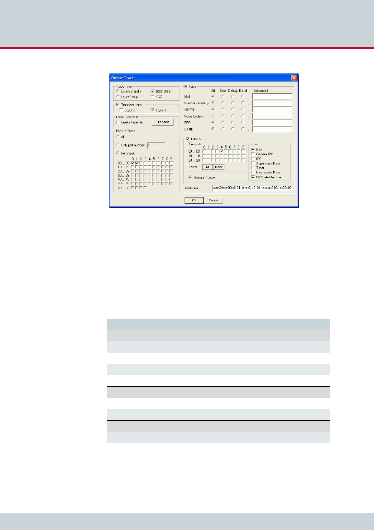
10 System maintenance and software update
Page 158CELLX 16.2
Figure 10.1 GATE Manager: online trace activation window
CELLXs offer two different types of trace:
Online - trace information is immediately displayed in the GATE Manager’s trace
window.
Offline - trace information is written to a file on the CELLX.
CELLX systems create trace files when the TraceLog=file entry is present in the pabx.cfg. Trac-
es can be activated via remote administration (GATE Manager or FTP).
The following table describes the fields that are on the online trace activation window. For
offline traces, some fields are not provided.
Table 10.10 Online trace activation window
Field Description
Trace Type
Layer 2 and 3 Select this option if the trace is to contain layer 2 and 3 messages.
Layer 3 only Select this option if the trace is to contain layer 3 messages only.
DSS1/NI2 Select this option if the trace is to contain DSS1/NI2 messages only.
SS7 For SS7 messages, select this option.
Translate Trace
Layer 2 To translate layer 2 messages into plain text, select this option.
Layer 3 To translate layer 3 messages into plain text, select this option.
Local Trace File
Create Trace File Check this box if you want to store a trace file locally on your computer.
File Name Click this button to change the default directory and file name of the
local trace file.
10 System maintenance and software update
Page 159CELLX 16.2
Trace output format
The following entries appear at the beginning and end of each trace:
DD.MM.YY-hh:mm:ss.ss, Start
DD.MM.YY-hh:mm:ss.ss, End
– DD = day
– hh = hour
– MM = month
– mm = minute
– YY = year
– ss.ss = hundredths of seconds
Ports to Trace
All Select this option to trace all ports.
Only Port Number Enter here the port which you want to trace.
Port Mask Select from this port mask which ports you want to trace.
IP Trace
Mail, Number Portability,
vGATE, ...
Contains a list of port-independent trace options. The different options
can be limited to error messages, debug messages, or detailed trace
output. The Advanced field is for TELES support usage only.
For an explanation of the different trace option please refer to
Chapter 10.9 Trace options on page 157.
CASR2
Timeslots Select which of the channels you want to trace for the CASR2 ports.
General Trace Check this box if you want to run a general trace for the different
timeslots.
Level Select which special type of information you want to trace for the dif-
ferent timeslots.
Additional The following additional entries are possible. The number behind the
colon referes to the trace level. 0 = no traces, 1 = few traces, 2 = many
traces, 3 = very many traces (only nstanl).
autodial:0 for auto dial trace messages
fctrans:trclevel=debug for ISDN facility to SIP converter messages
nstanl:0 for call routing trace messages
radius:0 for RADIUS trace messages
rtman:0 for routing manager trace messages
s0:0 for BRI trace messages
s2m:0 for PRI and switching matrix trace messages
voip:noreg to suppress traces of REGISTER and responses
Please bear in mind that the volume of trace readouts can grow quite large, so that faulty
transmission of the trace data may result with remote maintenance. A trace at full capacity
can cause the system to crash.
Table 10.10 Online trace activation window (continued)
Field Description
i
i

10 System maintenance and software update
Page 160CELLX 16.2
Traces appear in the following format:
[<hh:mm:ss>] <module>[<port>]: <trace>
<module>
– s = send for PRI/BRI or mobile ports
– r = receive for PRI/BRI or mobile ports
– x = send to VoIP destinations
– y = receive from VoIP destinations
– i = information messages and internal trace outputs between VoIP and the other
interfaces (ISDN, mobile)
– a = VoIP controllers RTCP output
–m = mail output
– g = remote output
<port>
– port number (controller number in the pabx.cfg) or 255 if a service is used
<trace>
– output in the defined syntax for the module
10.7.1 ISDN trace output
Trace output for DSS1 are in hexadecimal notation. You can use the external tool Trace-
View.exe to translate offline trace output. You will find the tool in the Software folder on
the enclosed CD. The GATE Manager’s trace window can also display translated online traces.
The following example shows an untranslated DSS1 trace.
Example 10.4 ISDN trace output
17.05.06-09:54:40,Start 11.7a (L3)
[09:55:14.58] r[00]: 00 01 02 02 08 02 00 02 05 04 03 80 90 a3 18 03 a1 83 81 6c
02 81 31 70 06 81 31 32 33 34 35 7d 02 91 81
[09:55:14.58] s[00]: 02 01 02 04 08 02 80 02 0d 18 03 a9 83 81
[09:55:14.58] s[01]: 00 01 a8 9a 08 02 00 46 05 04 03 80 90 a3 18 03 a1 83 89 6c
02 81 31 70 06 81 31 32 33 34 35 7d 02 91 81
[09:55:14.58] r[01]: 02 01 9a aa 08 02 80 46 0d 18 03 a9 83 89
[09:55:14.86] r[01]: 02 01 9c aa 08 02 80 46 01
[09:55:14.86] s[00]: 02 01 04 04 08 02 80 02 01
[09:55:16.73] r[01]: 02 01 9e aa 08 02 80 46 07 29 05 05 07 01 09 33 4c 07 01 81
31 32 33 34 35
[09:55:16.73] s[01]: 00 01 aa a0 08 02 00 46 0f
[09:55:16.73] s[00]: 02 01 06 04 08 02 80 02 07 29 05 05 07 01 09 32 4c 07 01 81
31 32 33 34 35
[09:55:16.73] r[00]: 00 01 04 08 08 02 00 02 0f
[09:55:44.30] r[00]: 00 01 06 08 08 02 00 02 45 08 02 80 90
[09:55:44.35] s[01]: 00 01 ac a0 08 02 00 46 45 08 02 80 90
[09:55:46.71] r[01]: 02 01 a0 ae 08 02 80 46 4d
[09:55:46.71] s[01]: 00 01 ae a2 08 02 00 46 5a
[09:55:46.71] s[00]: 02 01 08 08 08 02 80 02 4d
[09:55:46.71] r[00]: 00 01 08 0a 08 02 00 02 5a
17.05.06-09:51:33,End

10 System maintenance and software update
Page 161CELLX 16.2
10.7.2 GSM/CDMA/UMTS trace output
The trace output for GSM appears in hexadecimal notation. Its format is the same as that for
ISDN output. Table 10.11 and Table 10.12 describe the contents of GSM trace output.
Table 10.11 Request messages to the GSM module
Hex Value Description
00 Setup
01 Connect
02 Disconnect
03 SMS
04 DTMF
05 Set Config
06 Get Config
07 LED
08 Restart
09 Switch SIM
Table 10.12 Incoming, indication message from the GSM module
Hex Value Description
0B Alert
0C Voice Indication
0D Connect
0E DTMF
0F Setup
10 Disconnect
11 SMS
12 SMS Confirmation
13 Error
16 Get Config Confirmation
18 Dial-End Call Proceeding
19 USSD
1A Restart Indication

10 System maintenance and software update
Page 162CELLX 16.2
The following example shows a GSM call through the fourth GSM controller.
10.7.3 VoIP trace output
As described above in Chapter 10.7 Trace, there are four modules for VoIP traces. The groups
x (send), y (receive) and i (information and internal output) appear when a Layer2 or Layer3
offline or online trace is started. Group a (RTCP output) only appears when the module Voice
Codecs is active.
Particularly in the case of VoIP connections (protocols H.323 and SIP), the trace output is quite
extensive and abbreviations make it difficult to keep track of the results. The following list
contains a description of H.323 output.
Output for the signaling protocol SIP is transmitted in ASCII and translated for better legibility.
Since they are displayed unabridged, no description is necessary. Information and internal
output traces correspond with the H.323 output and are described in the following tables.
For ENUM, please refer to Chapter 10.7.3.5 ENUM output.
In general, the following rules apply for this trace output:
The information is thoroughly analyzed where it is received (all rcv messages).
Example 10.5 GSM call through fourth GSM controller
Status Request
[14:57:51.80] s[04]: 06
Status Information:
[14:57:51.80] r[04]: 16
Setup Request:
[14:57:52.29] s[04]: 00 4c 93 04 00 00 00 35 36 36 37 00 35 38 2c 36 34 36 2c 33
30 2c 2c 2c 30 2c 2c 2c 30 2c 32 36 32 2c 30 37 2c 00 72 64 09 75 70 20 7b 64 35
7d 20 27 2e 2e 2b 43 43 45 44 3a 20 32 36 32 2c 30 37 2c 34
Dial End:
[14:57:55.47] r[04]: 18
Alert:
[14:57:55.63] r[04]: 0b
Connect Indication:
[14:57:56.63] r[04]: 0d
Disconnect Request:
[14:59:54.13] s[04]: 02 4c 93 00
Disconnect Indication:
[14:59:54.19] r[04]: 10
Table 10.13 H.323 output
Packet Description
h225 H.225-protocol messages.
h245 H.245-protocol messages.
pstn Messages of the internal protocol interface that
provides the interface to the other interfaces PRI,
BRI and GSM.
rcv Coming from the IP network or the internal pro-
tocol interface; appears with <dir> in the trace
lines.
snd Sending to the IP network or the internal proto-
col interface; appears with <dir> in the trace
lines.

10 System maintenance and software update
Page 163CELLX 16.2
10.7.3.1 Interface IP network
Establish H.323 session
Usually there is trace output that displays a new H.323 session. The direction is crucial (wheth-
er the call is going into or coming out of the IP network).
The outut syntax is h225connect to <ip address> cr <cr> s <si> for calls going into
the IP network and h225accept from <ip address> s <si> for calls coming out of the
IP network.
H.225 signaling output
The following trace results are for a call coming from the IP network. rcv will appear at <dir>
and signifies the direction: h225<dir> tpkt msg 0x<mt> h225cr <cr> addr <ip ad-
dress>.
Table 10.14 H.323 session
Trace Output Description
connect to Outgoing VoIP call
accept from Incoming VoIP call
<ip address> Peer's IP address
cr <cr> Call reference (corresponds with the internal
protocol interface's PSTN call reference)
s <si> Session ID
Table 10.15 H.225 signaling
Trace Output Description
<mt> The ETS message type in hexadecimal; can con-
sist of values listed in Table 10.16.
<hcr> H.225 call reference in hexadecimal (does not
have to be unique when calls come from multiple
peers).
<ip address> The peer's IP address.
Table 10.16 ETS message types
Hex Value Message Type
1 Alerting
2Call Proceeding
3 Progress
5Setup
7 Connect
DSetup Acknowledge

10 System maintenance and software update
Page 164CELLX 16.2
The following lines show the packet contents in detail:
h225 decode rc 0, q931 msg 0x<mt> = 0, len <length>
h225<type> <mt> voipcfg addr <ip address> rc 0 compr <codec>
h225<type> <mt> h225cr <hcr> FS:<bool> (<codec>,<ip address>,<port>)
TUNN:<bool> H245:<bool>(<ip address>,<port>)
h225<type> <mt> h225cr <hcr> cr <cr>
5A Release Complete
62 Facility
6E Notify
7B Information
7D Status
Table 10.16 ETS message types (continued)
Hex Value Message Type
Table 10.17 Incoming VoIP calls
Trace Output Description
<mt> Message type in hexadecimal as per ETS stan-
dard (see Table 10.16) or written out as a name.
len <length> Packet length in bytes.
h225<type> H.225 rcv or send; received or sent from the IP
network.
addr <ip address> Peer's IP address.
compr <codec> Peer's compression list (see Table 10.18).
FS<bool> FastStart offered in the signaling packet or not.
(<codec>, Lists codecs offered (seeTable 10.38).
<ip address>, Peer's IP address for RTP data.
<port>) Peer's port for RTP Data.
Tunn<bool> Shows whether or not tunneling is offered as a
signaling variant.
H245<bool> Shows an extra H.245 session.
(ip address, Peer's IP address.
port) Peer's port.
h225cr <hcr> H.225 message's call reference (does not have to
be unique when calls come from multiple VoIP
peers).
cr <cr> Internal call reference (always unique for the
call).

10 System maintenance and software update
Page 165CELLX 16.2
When the call is sent in the direction of the IP network, the trace will include only the most
important information: h225<type> <mt1> dad <num> cr <cr>.
Table 10.18 Compression codecs used
Synonym Codec
A G.711Alaw64k
BG.711Ulaw64k
C G.7231
DG.728
E G.729
FgsmFullRate
G T.38fax
OG.729A
P G.72616
QG.72624
R G.72632
SG.729B
T G.729AB
UG.729E
V G.723L
WTransparent
X G.721
YiLBC20
ZiLBC30
Table 10.19 Calls to the IP network 1
Trace Output Description
<mt> Message type written out; if a decimal number
appears here, it will be translated as per Table
10.16.
<num> Called party number.
<cr> Call reference.

10 System maintenance and software update
Page 166CELLX 16.2
Or: h225<type> callproc typ <mt> cr <cr>.
RTP/RTCP output
The RTP/RTCP output displays whether the signaling information corresponds with the con-
tents of the compression chips. The output occurs when a media channel is set up or torn
down:
rtp start cr <cr> ch <ch> li <li> ri <ri> st <st> fx <fx> cp <comp> txm
<factor>.
The RTP stop message has the following syntax: rtp stop cr <cr>1 ch <ch>.
The following output shows the RTCP packet statistics:
Table 10.20 Calls to the IP network 2
Trace Output Description
<mt> The ETS message type in hexadecimal.
<cr> Call reference.
Table 10.21 RTP/RTCP output
Trace Output Description
<cr> Call reference.
<ch> The internal media channel used.
<li> 1 appears when the local RTP address (and port)
has been defined.
<ri> 1 appears when the remote RTP address (and
port) have been established.
<st> 0 appears if the channel's voice packetizer has
not yet been started. 1 appears if the voice pack-
etizer can receive, but not send. 2 appears when
the voice packetizer can receive and send.
<fx> 1 appears when T.38 (fax) is used, otherwise 0.
<comp> The codec used, as per Table 10.18.
<factor> Multiplication factor for default frame size
(20ms, 30 ms for G.723).
Table 10.22 RTP stop message
Trace Output Description
<cr> Call reference.
<ch> The internal media channel used.

10 System maintenance and software update
Page 167CELLX 16.2
rtcp <ch>: SR <dir> pc <pc> oc <oc> ji <ji> rt <rt> fl <fl> cl <cl>.
The following output shows the jitter buffer status:
a[<controller>]: <VoIPcodecChipType> ch <ch> jitter buffer n1 n2 n3n4 n5
n6 n7 n8.
An RTP connection has ended when the following trace output appears:
Table 10.23 RTCP packet statistics
Trace Output Description
<ch> The internal media channel used.
SR<dir> Rx sender report (received) is more interesting,
since it comes from the peer. Tx sender report
(transmitted).
<pc> Packet count (number of packets transmitted/re-
ceived).
<oc> Octet count (number of octets transmitted/re-
ceived).
<ji> Delay jitter [msec].
<rt> Round-trip local<->remote, round-trip delay
[msec].
<fl> Fraction lost: Fraction of packets lost [8lsb].
<cl> Cumulative lost: number of lost packets [24lsb].
Table 10.24 Jitter buffer status
Trace Output Description
n1 SteadyStateDelay in milliseconds
n2 NumberOfVoiceUnderrun
n3 NumberOfVoiceOverrun
n4 NumberOfVoiceDecoderBfi (bfi = bad frame in-
terpolation)
n5 NumberOfVoicePacketsDropped
n6 NumberOfVoiceNetPacketsLost
n7 NumberOfIbsOverrun (ibs = in band signaling)
n8 NumberOfCasOverrun

10 System maintenance and software update
Page 168CELLX 16.2
a[<controller>]: <VoIPcodecChipType> stop ch=<ch>.
The following output results when the codec changes for a fax connection:
a[<controller>]: ac49x ch <ch> fax/data n1 n2 n3.
Table 10.25 RTP stop message (VP module)
Trace Output Description
<ch> The internal media channel used.
Table 10.26 Codec change for fax
Trace Output Description
n1 Fax bypass flag:
0Voice, data bypass or fax relay
1Fax bypass
n2 Signal detected on decoder output (see Table
10.27)
n3 Signal detected on encoder input (see Table
10.27)
Table 10.27 fax or data signal event
Value Definition Description
0SILENCE_OR_UNKNOWN Undefined (unknown signal or
silence)
1FAX_CNG CNG-FAX (calling fax tone,
1100 Hz)
2ANS_TONE_2100_FAX_CED_O
R_MODEM
FAX-CED or modem-ANS (an-
swer tone, 2100 Hz)
3ANS_TONE_WITH_REVERSALS ANS (answer tone with rever-
sals)
4ANS_TONE_AM ANSam (AM answer tone)
5ANS_TONE_AM_REVERSALS ANSam (AM answer tone with
reversals)
6FAX_V21_PREAMBLE_FLAGS FAX-V.21 preamble flags
7FAX_V8_JM_V34 FAX-V.8 JM (fax call function,
V.34 fax)
8VXX_V8_JM_VXX_DATA V.XX-V.8 JM (data call func-
tion, V-series modem)
9V32_AA V.32 AA (calling modem tone,
1800 Hz)
10 V22_USB1 V.22 USB1 (V.22(bis) unscram-
bled binary ones)

10 System maintenance and software update
Page 169CELLX 16.2
Fax relay is activated for the corresponding channel:
a[<controller>]: Ac49xActivateFaxRelayCommand(1) ch <ch> rc <cr>.
The following output shows various values for fax transmission (see Table 10.28 for a descrip-
tion of the values):
a[<controller>]: ac49x ch <ch> faxrelay: n1 n2 n3 n4 n5 n6 n7 n8 n9 n10 n11
n12 n13 n14 n15 n16 n17.
11 V8_BIS_INITIATING_DUAL_TO
NE
V.8bis initiating dual tone
(1375 Hz and 2002 Hz)
12 V8_BIS_RESPONDING_DUAL_T
ONE
V.8bis responding dual tone
(1529 Hz and 2225 Hz)
13 VXX_DATA_SESSION V.XX data session
14 V21_CHANNEL_2 V.21 channel 2 (mark tone,
1650 Hz)
15 V23_FORWARD_CHANNEL V.23 forward channel (mark
tone, 1300 Hz)
16 V21_CHANNEL_1=18 V.21 channel 1 (mark tone,
980 Hz)
17 BELL_103_ANSWER_TONE Bell 103 answer tone, 2225 Hz
18 TTY TTY
19 FAX_DCN FAX-DCN (G.3 fax disconnect
signal)
Table 10.27 fax or data signal event (continued)
Value Definition Description
Table 10.28 Fax status
Value Field Name Description
n1 UnableToRecoverFlag (0 no, 1 yes) Unable to recover lost packet
n2 IllegalHdlcFrameDetectedFlag (...) Illegal HDLC frame detected
n3 FaxExitWithNoMcfFrameFlag Fax exit with no MCF Frame
n4 HostTransmitOverRunFlag Channel received a buffer overrun
n5 HostTransmitUnderRunFlag Channel received a buffer underrun
n6 InternalErrorFlag Internal error
n7 ReceivedBadCommandFlag A bad command was received. Words 8
and 9 describe the bad command
n8 TimeOutErrorFlag A timeout error occurred

10 System maintenance and software update
Page 170CELLX 16.2
n9 T30RxState T.30 receive state
0 Init (initialization state)
1 CNG (calling tone)
2 CED (called terminal identifica-
tion)
3 V21 (switch to V21)
4 NSF (non-standard facilities)
5 NSC (non-standard (facilities)
command)
6 CSI (called subscriber identifi-
cation)
7 CIG (calling subscriber identifi-
cation)
8 DIS (digital identification signal)
9 DTC (digital transmit com-
mand)
10 NSS (non-standard services)
11 TSI (transmitting subscriber ID)
12 DCS (digital command signal)
13 CTC (continue to correct)
14 CRP (command repeat)
15 DCN (disconnect)
16 Pre-message response
17 Post-message response
18 Post-message command
19 VXX (receive illegal high-speed
signal)
20 TCF (training check function
21 Fax image
22 V.8 CI (calling indicator (re-
served))
23 V.8 CM (calling menu)
24 V.8 (joint menu)
n10 T30TxState T.30 transmit state. For values, see the
entry for T30RxState above.
n11 NumberOfTransferredPages Number of transmitted or received pag-
es positively confirmed by answering
fax.
n12 BadInputPacketId Sequence number of Bad Input UDPTL
packet, or the first two bytes of the in-
put TCP packet. The field is relevant if
the “Bad CMD” or the “Unable Recov-
er” bit is set.
n13 BadInputPacketTotalSize The total number of bytes in a bad fax
packet.
n14 FaxBitRate 0 Undefined or 300 bpx
(T.30 control signals)
1 2400 bps
2 4800 bps
3 7200 bps
4 9600 bps
5 12000 bps
6 14400 bps
7-15 Reserved
Table 10.28 Fax status (continued)
Value Field Name Description

10 System maintenance and software update
Page 171CELLX 16.2
The following output appears when the compression chip detects DTMF tones:
a[<controller]: ac49x ch <ch> ibs <dtmf> <dir> <mode> <lev> <dur>.
10.7.3.2 Internal protocol interface (to ISDN, mobile)
These trace outputs always begin with the keyword pstn, followed by the direction and the
message type. The message is then either concluded or other information follows:
n15 DemodulationStatus 0 EQM and Timing Off-
set fields are invalid.
1 EQM and Timing Off-
set fields are valid.
n16 EyeQualityMonitor (EQM) Eye Quality Monitor measure for TCF or
fax image. The value of 0 corresponds
to the best quality of demodulation.
Values greater than 100 have a nega-
tive influence on the quality of the fax
image.
n17 TimingOffsetPpm Timing Offset (ppm) recovered during
demodulation of TCF or fax image. The
offset is a short integer equal to the
sum of the sampling rate error and the
sending fax baud rate offset. The value
is in integers and and may not exceed
50 ppm in the following ranges during
fax transmission (T30TxState):
65535 – 65486 (-50ppm) 0 – 50
(+50ppm)
Table 10.28 Fax status (continued)
Value Field Name Description
Table 10.29 DTMF tone detection
Trace Output Description
<ch> Media channel
<dtmf> Detected DTMF tone in the stream or as per
RFC2833
<dir> Direction
0Coming from BRI/analog
1Coming from VoIP
<mode> 0Tone has ended
1Tone has been detected
<lev> Signal level in -dBm
<dur> Tone duration

10 System maintenance and software update
Page 172CELLX 16.2
pstn<type> <mt1> dad <num> oad <num> cc <value> cc <cc> id <id> c/c <ctrl>/
<ch> cr <cr>.
Output also appears when a call comes from the internal protocol interface and is assigned
to a VoIP profile. The characters appear in front of the colon in the routing entry:
pstnrcv get_voipcfg <voip profile> compr <list>
Assignment of media channel used for the internal interface and the ISDN call reference for
the VoIP call's appears as follows:
pstnrcv bchanind cr <cr> ch <chan> isdncr <icr>
Table 10.30 Internal protocol interface
Trace Output Description
<type> Direction from (rcv) or to (snd) the internal pro-
tocol interface.
<mt1> Message type written out; if a decimal number
appears, it will be translated as per Table 10.16.
<num> DAD<num> = called party number, OAD<num>
= calling party number.
<cc> Value for OAD field element:
20 OAD network type provided
40 OAD with sending complete
80 OAD presentation restricted
<id> Internal ident for the call leg.
<ctrl> Controller used (counting starts with 0).
<ch> Media channel used (counting starts with 1).
<cr> Internal call reference /, followed by 0 or call ref-
erence of the VoIP leg.
Table 10.31 Received from PSTN 1
Trace Output Description
<voip profile> Defines the VoIP profile to be used.
<list> Defines the compression algorithms offered.
Table 10.32 Received from PSTN 2
Trace Output Description
<cr> Call reference.
<chan> Media channel used for the internal protocol in-
terface (DSS1).
<icr> Call reference for the internal protocol interface
(DSS1).

10 System maintenance and software update
Page 173CELLX 16.2
10.7.3.3 H.245 messages
The following trace output is possible: h245<dir>(<tt>) cr <cr>.
Following this trace output, either a detailed description of the message and its corresponding
message type, including negotiating information, or trace output elements that are explained
later appear. The most important message types that contain further information elements
are as follows:
TerminalCapabilitySet peer=<comp> cfg=<comp>
TerminalCapabilitySet <comp>
Table 10.33 H.245 messages
Trace Output Description
<dir> The message's direction; rcv (incoming from
the peer) or snd (sent message).
<tt> H.245 transport type.
<cr> Internal call reference.
Table 10.34 Codec used
Trace Output Description
<comp> List of compression codecs offered (see Table
10.18), the list of the peer's codecs appears be-
hind peer, and cfg shows which codecs are de-
fined in the VoIP profile

10 System maintenance and software update
Page 174CELLX 16.2
The output syntax for the logical channel parameters is as follows:
OpenLogicalChannel cn=<cn> cpr=<comp> sessid=<sid> ctrl=<ip address>:<rtcp
port>
OpenLogicalChannelAck cn=<cn> sessid=<sid> media=<ip address>:<rtp port>
The trace output is as follows when the message type is not translated or is ignored:
h245<dir>(<tt>) cr <cr> unknown msg <hmt> <hmi>
Table 10.35 Logical channel parameters
Trace Output Description
<cn> H.245 channel number per H.225 connection.
<sid> Session ID.
<comp> Codec used (see Table 10.18).
<ip address> Protocol peer IP address.
<rtcp port> Port used for the protocol RTCP.
<rtp port> Port used for the protocol RTP.
Table 10.36 H.245 parameters
Trace Output Description
hmt The H.245 message type (multimedia system
control message type), (Table 10.37).
hmi The H.245 message ID (see Table 10.38, Table
10.39, Table 10.40, Table 10.41).
Table 10.37 Multimedia system control message types
ID Message
0 (Table 10.38) Request
1 (Table 10.39)Response
2 (Table 10.40) Command
3 (Table 10.41)Indication

10 System maintenance and software update
Page 175CELLX 16.2
Depending on the system control message type, one of the following message IDs appear:
Table 10.38 Message IDs for request message
ID Message
0 NonStandard
1MasterSlaveDetermination
2 TerminalCapabilitySet
3OpenLogicalChannel
4 CloseLogicalChannel
5RequestChannelClose
6 MultiplexEntrySend
7RequestMultiplexEntry
8 RequestMode
9RoundTripDelayRequest
10 MaintenanceLoopRequest
11 CommunicationModeRequest
12 ConferenceRequest
13 MultilinkRequest
14 LogicalChannelRateRequest
Table 10.39 Message IDs for response message
ID Message
0 NonStandard
1MasterSlaveDeterminationAck
2 MasterSlaveDeterminationReject
3TerminalCapabilitySetAck
4 TerminalCapabilitySetReject
5OpenLogicalChannelAck
6 OpenLogicalChannelReject
7CloseLogicalChannelAck
8 RequestChannelCloseAck
9RequestChannelCloseReject
10 MultiplexEntrySendAck
11 MultiplexEntrySendReject
12 RequestMultiplexEntryAck

10 System maintenance and software update
Page 176CELLX 16.2
13 RequestMultiplexEntryReject
14 RequestModeAck
15 RequestModeReject
16 RoundTripDelayResponse
17 MaintenanceLoopAck
18 MaintenanceLoopReject
19 CommunicationModeResponse
20 ConferenceResponse
21 MultilinkResponse
22 LogicalChannelRateAcknowledge
23 LogicalChannelRateReject
Table 10.40 Message IDs for command message
ID Message
0 NonStandard
1MaintenanceLoopOffCommand
2 SendTerminalCapabilitySet
3EncryptionCommand
4 FlowControlCommand
5EndSessionCommand
6 MiscellaneousCommand
7CommunicationModeCommand
8 ConferenceCommand
9h223MultiplexReconfiguration
10 NewATMVCCommand
11 MobileMultilinkReconfigurationCommand
Table 10.41 Message IDs For indication message
ID Message
0 NonStandard
1FunctionNotUnderstood
2 MasterSlaveDeterminationRelease
Table 10.39 Message IDs for response message (continued)
ID Message

10 System maintenance and software update
Page 177CELLX 16.2
10.7.3.4 RAS (registration, admission, status)
As a general rule, the most important terminal and gatekeeper messages appear written out
with the gatekeeper's IP address (<ip addr>).
Here is the output syntax for gatekeeper discovery requests:
H225 GatekeeperRequest to <ip addr> (s 131)
H225 GatekeeperConfirm <ip addr>
H225 GatekeeperReject <ip addr> reason <reason>
Here is the output syntax for endpoint registration requests:
3TerminalCapabilitySetRelease
4 OpenLogicalChannelConfirm
5RequestChannelCloseRelease
6 MultiplexEntrySendRelease
7RequestMultiplexEntryRelease
8 RequestModeRelease
9MiscellaneousIndication
10 JitterIndication
11 h223SkewIndication
12 NewATMVCIndication
13 UserInput
14 h2250MaximumSkewIndication
15 McLocationIndication
16 ConferenceIndication
17 VendorIdentification
18 FunctionNotSupported
19 MultilinkIndication
20 LogicalChannelRateRelease
21 FlowControlIndication
22 MobileMultilinkReconfigurationIndication
Table 10.41 Message IDs For indication message (continued)
ID Message
Table 10.42 RAS
Trace Output Description
<reason> Gatekeeper reject reason, see Table 10.46.

10 System maintenance and software update
Page 178CELLX 16.2
H225 GkRegistration to <ip addr>
H225 RegistrationConfirm <ip addr>
H225 RegistrationReject <ip addr> reason <reason>
Below you see the output syntax for bandwith availability indication:
H225 GkResourcesAvailableIndicate to <ip addr> (<act chan> <max chan>)
H225 ResourcesAvailableConfirm <ip addr>
Here is the output syntax for call admission requests:
H225 GkAdmission cr <cr> to <ip addr>
H225 AdmissionConfirm <ip addr> cr <cr>
H225 AdmissionReject <ip addr> reason <reason>
Here is the output syntax for call teardown requests:
H225 GkDisengage cr <cr> to <ip addr>
H225 DisengageConfirm <ip addr>
Here is the output syntax for registration release requests:
H225 UnregistrationRequest <ip addr>
H225 GkUnregistrationConf to <ip addr>
All other messages appear as follows:
H225 unknown msg from Gk <ip addr>: <code>
Table 10.43 Gatekeeper 1
Trace Output Description
<reason> Registration reject reason, see Table 10.47.
Table 10.44 Gatekeeper 2
Trace Output Description
<reason> Admission reject reason, see Table 10.48.
Table 10.45 Gatekeeper 3
Trace Output Description
<code> Unknown gatekeeper message, see Table 10.49.

10 System maintenance and software update
Page 179CELLX 16.2
Table 10.46 Gatekeeper reject reason
ID Reject Reason
0 resourceUnavailable
1terminalExcluded
2 invalidRevision
3undefinedReason
4 securityDenial
5genericDataReason
6 neededFeatureNotSupported
Table 10.47 Registration reject reason
ID Reject Reason
0 DiscoveryRequired
1InvalidRevision
2 InvalidCallSignalAddress
3InvalidRASAddress
4 DuplicateAlias
5InvalidTerminalType
6 UndefinedReason
7TransportNotSupported
8 TransportQOSNotSupported
9ResourceUnavailable
10 InvalidAlias
11 SecurityDenial
12 RullRegistrationRequired
13 AdditiveRegistrationNotSupported
14 InvalidTerminalAliases
15 GenericDataReason
16 NeededFeatureNotSupported
Table 10.48 Admission reject reason
ID Reject Reason
0 CalledPartyNotRegistered
1InvalidPermission

10 System maintenance and software update
Page 180CELLX 16.2
2 RequestDenied
3UndefinedReason
4 CallerNotRegistered
5RouteCallToGatekeeper
6 InvalidEndpointIdentifier
7ResourceUnavailable
8 SecurityDenial
9QosControlNotSupported
10 IncompleteAddress
11 AliasesInconsistent
12 RouteCallToSCN
13 ExceedsCallCapacity
14 CollectDestination
15 CollectPIN
16 GenericDataReason
17 NeededFeatureNotSupported
Table 10.49 Unknown gatekeeper messages
ID Message
0 GatekeeperRequest
1GatekeeperConfirm
2 GatekeeperReject
3RegistrationRequest
4 RegistrationConfirm
5RegistrationReject
6 UnregistrationRequest
7UnregistrationConfirm
8 UnregistrationReject
9AdmissionRequest
10 AdmissionConfirm
11 AdmissionReject
12 BandwidthRequest
Table 10.48 Admission reject reason (continued)
ID Reject Reason

10 System maintenance and software update
Page 181CELLX 16.2
10.7.3.5 ENUM output
This output is assigned to group i and occurs with Layer2 and Layer3 traces:
i[<controller>]: enum_query cr <CR> ch <CH>: <num> -> <length> <<answer
pattern>>.
13 BandwidthConfirm
14 BandwidthReject
15 DisengageRequest
16 DisengageConfirm
17 DisengageReject
18 LocationRequest
19 LocationConfirm
20 LocationReject
21 InfoRequest
22 InfoRequestResponse
23 NonStandardMessage
24 UnknownMessageResponse
25 RequestInProgress
26 ResourcesAvailableIndicate
27 ResourcesAvailableConfirm
28 InfoRequestAck
29 InfoRequestNak
30 ServiceControlIndication
31 ServiceControlResponse
Table 10.49 Unknown gatekeeper messages (continued)
ID Message
Table 10.50 ENUM output
Trace Output Description
<cr> Call reference.
<ch> Media channel.
<num> Phone number converted into ENUM domain
format.
<length> Length of the answer field in the DNS response
in bytes. 0 appears if the number was not found.
<answer pattern> Displays the DNS response. 0 appears if the num-
ber was not found.

10 System maintenance and software update
Page 182CELLX 16.2
10.7.3.6 Examples
The following examples are offline traces. You can generate them using the GATE Manager
or FTP commands. The filename is trace.log. The following cases appear in the examples:
Incoming H.323 call with FastStart (please see "Incoming H.323 call with FastStart" on
page 182 )
Outgoing H.323 call with FastStart (please see "Outgoing H.323 call with FastStart" on
page 183)
Fax call (please see "Fax call" on page 184)
Incoming H.323 call with FastStart
Example 10.6 Incoming H.323 call with FastStart
[15:25:13.65] i[02]: h225accept from 172.16.0.200 s 4
[15:25:13.75] y[02]: h225rcv tpkt msg 5 h225cr 8006 addr 172.16.0.200 pt 0
[15:25:13.75] y[02]: h225 decode rc 0, q931 msg 5 (0), len 364
[15:25:13.75] y[02]: h225rcv setup voipcfg addr 172.16.0.200 rc 0 <DF> compr EABG
[15:25:13.75] y[02]: h225rcv faststart <A1B1E1G0>
[15:25:13.75] y[02]: h225rcv setup oad 01 00 <111> <> dad 01 <123456> rad <> bc 038090a3 0101
[15:25:13.75] y[02]: h225rcv setup h225cr 8006 FS:1(E,172.16.0.200,29000) TUNN:1 H245:0(0,0)
[15:25:13.75] y[02]: h225rcv setup h225cr 8006 cr 7
[15:25:13.75] i[02]: pstnsnd setup dad 123456 oad 1 cr 7 s 4
[15:25:13.75] s[00]: 00 01 52 4c 08 02 00 08 05 04 03 80 90 a3 18 03 a1 83 87 6c 04 81 31 31 31 70 07 81
31 32 33 34 35 36 7d 02 91 81
[15:25:13.75] i[02]: pstnrcv connresp cr 7 acc 5 ch 1
[15:25:13.75] x[02]: h225snd callproc typ d cr 7 pri 0
[15:25:13.75] r[00]: 00 01 01 54
[15:25:13.75] r[00]: 02 01 4c 54 08 02 80 08 0d 18 03 a9 83 87
[15:25:13.75] s[00]: 02 01 01 4e
[15:25:14.33] r[00]: 02 01 4e 54 08 02 80 08 01
[15:25:14.33] s[00]: 02 01 01 50
[15:25:14.33] i[02]: pstnrcv alert cr 7 cls ff
[15:25:14.33] i[02]: rtp start cr 7 ch 1 li 1 ri 1 st 2 fx 0 cp E txm 1
[15:25:14.33] x[02]: h225snd callproc typ 1 cr 7 pri 8
[15:25:14.34] a[02]: vp start(201) ch=0 local=29000 remote=ac1000c8:29000 agg=0 pcm=0
[15:25:14.38] a[02]: vp rtcp 0: RR Tx pc 0 oc 0 ji -1 rt 0 fl -1 cl -1
[15:25:14.38] a[02]: vp ch 0: in 0 out 74
[15:25:15.57] r[00]: 02 01 50 54 08 02 80 08 07 29 05 06 03 18 0f 17 4c 06 01 81 31 37 33 31
[15:25:15.57] s[00]: 00 01 54 52 08 02 00 08 0f
[15:25:15.57] i[02]: pstnrcv connresp cr 7 acc 10 ch 255
[15:25:15.57] x[02]: h225snd callproc typ 7 cr 7 pri 0
[15:25:15.58] r[00]: 00 01 01 56
[15:25:17.01] a[02]: vp rtcp 0: SR Rx pc 110 oc 1816 ji 158 rt -1 fl 2 cl 1
[15:25:20.09] a[02]: vp rtcp 0: SR Tx pc 277 oc 5496 ji 164 rt 0 fl 0 cl 0
[15:25:20.09] a[02]: vp ch 0: in 18166 out 20646
[15:25:20.09] a[02]: vp rtcp 0: SR Rx pc 258 oc 4634 ji 208 rt -1 fl 0 cl 1
[15:25:23.32] a[02]: vp rtcp 0: SR Tx pc 441 oc 8776 ji 176 rt 0 fl 0 cl 0
[15:25:23.32] a[02]: vp ch 0: in 28966 out 32900
[15:25:24.68] y[02]: h225rcv tpkt msg 5a h225cr 8006 addr 172.16.0.200 pt 800e7800
[15:25:24.68] y[02]: h225 decode rc 0, q931 msg 5a (5), len 33
[15:25:24.68] y[02]: h225rcv relack h225cr 8006 FS:0(-,0,0) TUNN:1 H245:0(0,0)
[15:25:24.68] y[02]: h225rcv relack h225cr 8006 cau 0x10
[15:25:24.68] i[02]: rtp hold cr 7 ch 1
[15:25:24.68] s[00]: 00 01 56 52 08 02 00 08 45 08 02 80 90
[15:25:24.68] i[02]: h225 connection 4 terminated
[15:25:24.69] r[00]: 00 01 01 58
[15:25:25.89] r[00]: 02 01 52 58 08 02 80 08 4d
[15:25:25.89] s[00]: 00 01 58 54 08 02 00 08 5a
[15:25:25.94] i[02]: pstnrcv terminate connection (3201) cr 7 cau 1 err 16 state 17 ch 1 rsid 1
[15:25:25.94] i[02]: rtp stop cr 7 ch 1
[15:25:25.94] r[00]: 00 01 01 5a
[15:25:25.94] a[02]: vp ch 0: in 34096 out 38154
[15:25:25.94] a[02]: vp stop ch=0

10 System maintenance and software update
Page 183CELLX 16.2
Outgoing H.323 call with FastStart
Example 10.7 Outgoing H.323 call with FastStart
[15:04:09.12] r[00]: 02 01 46 48 08 02 22 54 05 04 03 80 90 a3 18 03 a9 83 94 6c 06 01 81 31 31 31 31 70
04 81 33 32 31 7d 02 91 81
[15:04:09.12] s[00]: 02 01 01 48
[15:04:09.12] s[00]: 00 01 48 48 08 02 a2 54 0d 18 03 a9 83 94
[15:04:09.12] i[02]: pstnrcv setup dad DF:321 oad 1111 cc 0 id 15d006
[15:04:09.12] i[02]: pstnrcv get_voipcfg <DF>
[15:04:09.12] i[02]: h225connect to 172.16.0.200 cr 6
[15:04:09.12] x[02]: h225snd setup dad 1 cr 6
[15:04:09.12] r[00]: 00 01 01 4a
[15:04:09.15] y[02]: h225rcv tpkt msg d h225cr 6 addr 172.16.0.200 pt 80412800
[15:04:09.15] y[02]: h225 decode rc 0, q931 msg d (11), len 32
[15:04:09.15] y[02]: h225rcv msg d (11) h225cr 6 FS:0(-,0,0) TUNN:1 H245:0(0,0)
[15:04:09.50] y[02]: h225rcv tpkt msg 1 h225cr 6 addr 172.16.0.200 pt 80412800
[15:04:09.50] y[02]: h225 decode rc 0, q931 msg 1 (3), len 121
[15:04:09.50] y[02]: h225rcv faststart <E1>
[15:04:09.50] y[02]: h225rcv alert h225cr 6 FS:1(E,172.16.0.200,29000) TUNN:1 H245:0(0,0)
[15:04:09.50] i[02]: rtp start cr 6 ch 1 li 1 ri 1 st 2 fx 0 cp E txm 1
[15:04:09.50] s[00]: 00 01 4a 48 08 02 a2 54 01 1e 02 80 88
[15:04:09.50] a[02]: vp start(201) ch=0 local=29000 remote=ac1000c8:29000 agg=0 pcm=0
[15:04:09.50] r[00]: 00 01 01 4c
[15:04:09.53] a[02]: vp rtcp 0: RR Tx pc 0 oc 0 ji -1 rt 0 fl -1 cl -1
[15:04:09.53] a[02]: vp ch 0: in 0 out 74
[15:04:11.79] y[02]: h225rcv tpkt msg 7 h225cr 6 addr 172.16.0.200 pt 80412800
[15:04:11.79] y[02]: h225 decode rc 0, q931 msg 7 (2), len 79
[15:04:11.79] y[02]: h225rcv connect h225cr 6 FS:0(-,0,0) TUNN:1 H245:0(0,0)
[15:04:11.79] i[02]: pstnsnd connect cr 6
[15:04:11.79] s[00]: 00 01 4c 48 08 02 a2 54 07
[15:04:11.80] r[00]: 02 01 48 4e 08 02 22 54 0f
[15:04:11.80] s[00]: 02 01 01 4a
[15:04:12.50] a[02]: vp rtcp 0: SR Rx pc 21 oc 394 ji 201 rt -1 fl 0 cl 0
[15:04:16.13] a[02]: vp rtcp 0: SR Tx pc 192 oc 3236 ji 196 rt 0 fl 0 cl 0
[15:04:16.13] a[02]: vp ch 0: in 14612 out 13796
[15:04:17.98] y[02]: h225rcv tpkt msg 5a h225cr 6 addr 172.16.0.200 pt 80412800
[15:04:17.98] y[02]: h225 decode rc 0, q931 msg 5a (5), len 33
[15:04:17.98] y[02]: h225rcv relack h225cr 6 FS:0(-,0,0) TUNN:1 H245:0(0,0)
[15:04:17.98] y[02]: h225rcv relack h225cr 6 cau 0x10
[15:04:17.98] i[02]: rtp hold cr 6 ch 1
[15:04:17.98] s[00]: 00 01 4e 4a 08 02 a2 54 45 08 02 80 90
[15:04:17.98] i[02]: h225 connection 4 terminated
[15:04:17.99] r[00]: 00 01 01 50
[15:04:18.04] r[00]: 02 01 4a 50 08 02 22 54 4d 08 02 84 90
[15:04:18.04] s[00]: 00 01 50 4c 08 02 a2 54 5a
[15:04:18.06] i[02]: pstnrcv terminate connection (3201) cr 6 cau 90 err 16 state 17 ch 1 rsid 1
[15:04:18.06] i[02]: rtp stop cr 6 ch 1
[15:04:18.06] r[00]: 00 01 01 52
[15:04:18.06] a[02]: vp ch 0: in 21288 out 20708
[15:04:18.06] a[02]: vp stop ch=0

10 System maintenance and software update
Page 184CELLX 16.2
Fax call
Example 10.8 Fax call
[16:00:40.44] i[02]: h225accept from 172.20.0.200 s 4
[16:00:40.49] y[02]: h225rcv tpkt msg 5 h225cr 8007 addr 172.20.0.200 pt 0
[16:00:40.49] y[02]: h225 decode rc 0, q931 msg 5 (0), len 251
[16:00:40.49] y[02]: h225rcv setup voipcfg addr 172.20.0.200 rc 0 <DF> compr EABG
[16:00:40.49] y[02]: h225rcv faststart <E0G0>
[16:00:40.49] y[02]: h225rcv setup oad 00 00 <> <> dad 01 <123456> rad <> bc 038090a3 0101
[16:00:40.49] y[02]: h225rcv setup h225cr 8007 FS:1(E,172.20.0.200,29000) TUNN:1 H245:0(0,0)
[16:00:40.49] y[02]: h225rcv setup h225cr 8007 cr 14
[16:00:40.49] i[02]: pstnsnd setup dad 123456 oad cr 14 s 4
[16:00:40.49] s[00]: 00 01 5a 54 08 02 00 09 05 04 03 80 90 a3 18 03 a1 83 88 70 07 81 31 32 33 34 35 36
7d 02 91 81
[16:00:40.49] i[02]: pstnrcv connresp cr 14 acc 5 ch 1
[16:00:40.49] x[02]: h225snd callproc typ d cr 14 pri 0
[16:00:40.50] r[00]: 02 01 54 5c 08 02 80 09 0d 18 03 a9 83 88
[16:00:40.67] r[00]: 02 01 56 5c 08 02 80 09 01
[16:00:40.67] i[02]: pstnrcv alert cr 14 cls ff
[16:00:40.67] i[02]: rtp start cr 14 ch 1 li 1 ri 1 st 2 fx 0 cp E txm 2
[16:00:40.67] x[02]: h225snd callproc typ 1 cr 14 pri 8
[16:00:40.70] a[02]: vp start(201) ch=0 local=29000 remote=ac1000c8:29000 agg=0 pcm=0
[16:00:40.74] a[02]: vp rtcp 0: RR Tx pc 0 oc 0 ji -1 rt 0 fl -1 cl -1
[16:00:40.74] a[02]: vp ch 0: in 0 out 74
[16:00:40.90] r[00]: 02 01 58 5c 08 02 80 09 07 29 05 06 03 18 0f 3b 4c 08 01 81 31 32 33 34 35 36
[16:00:40.90] s[00]: 00 01 5c 5a 08 02 00 09 0f
[16:00:40.90] i[02]: pstnrcv connresp cr 14 acc 10 ch 255
[16:00:40.90] x[02]: h225snd callproc typ 7 cr 14 pri 0
[16:00:41.98] a[02]: vp rtcp 0: SR Rx pc 134 oc 1340 ji 195 rt -1 fl 0 cl 0
[16:00:43.29] y[02]: h225rcv tpkt msg 62 h225cr 8007 addr 172.20.0.200 pt 80410800
[16:00:43.29] y[02]: h225 decode rc 0, q931 msg 62 (6), len 123
[16:00:43.29] y[02]: h225rcv facility h225cr 8007 FS:0(-,0,0) TUNN:1 H245:0(0,0)
[16:00:43.29] i[02]: h245rcv(1) cr 14 TerminalCapabilitySet peer=<EG> cfg=<EABG>
[16:00:43.29] i[02]: h245snd(1) cr 14 TerminalCapabilitySetAck
[16:00:43.29] i[02]: h245snd(1) cr 14 TerminalCapabilitySet <EABG>
[16:00:43.51] y[02]: h225rcv tpkt msg 62 h225cr 8007 addr 172.20.0.200 pt 80410800
[16:00:43.51] y[02]: h225 decode rc 0, q931 msg 62 (6), len 63
[16:00:43.51] y[02]: h225rcv facility h225cr 8007 FS:0(-,0,0) TUNN:1 H245:0(0,0)
[16:00:43.51] i[02]: h245rcv(1) cr 14 TerminalCapabilitySetAck
[16:00:43.72] y[02]: h225rcv tpkt msg 62 h225cr 8007 addr 172.20.0.200 pt 80410800
[16:00:43.72] y[02]: h225 decode rc 0, q931 msg 62 (6), len 74
[16:00:43.72] y[02]: h225rcv facility h225cr 8007 FS:0(-,0,0) TUNN:1 H245:0(0,0)
[16:00:43.72] i[02]: h245rcv(1) cr 14 RequestMode t38=1
[16:00:43.72] i[02]: h245snd(1) cr 14 RequestModeAck
[16:00:43.73] i[02]: h245snd(1) cr 14 CloseLogicalChannel cn=1
[16:00:43.73] i[02]: h245snd(1) cr 14 OpenLogicalChannel cn=1 cpr=G sessid=1 ctrl=172.20.0.100:29001
[16:00:43.73] y[02]: h225rcv tpkt msg 62 h225cr 8007 addr 172.20.0.200 pt 80410800
[16:00:43.73] y[02]: h225 decode rc 0, q931 msg 62 (6), len 68
[16:00:43.73] y[02]: h225rcv facility h225cr 8007 FS:0(-,0,0) TUNN:1 H245:0(0,0)
[16:00:43.73] i[02]: h245rcv(1) cr 14 CloseLogicalChannel cn=1 (1)
[16:00:43.73] i[02]: h245snd(1) cr 14 CloseLogicalChannelAck cn=1
[16:00:43.73] y[02]: h225rcv tpkt msg 62 h225cr 8007 addr 172.20.0.200 pt 80410800
[16:00:43.73] y[02]: h225 decode rc 0, q931 msg 62 (6), len 92
[16:00:43.73] y[02]: h225rcv facility h225cr 8007 FS:0(-,0,0) TUNN:1 H245:0(0,0)
[16:00:43.73] i[02]: h245rcv(1) cr 14 OpenLogicalChannel cn=1 cpr=G sessid=1 ctrl=172.20.0.200:29001
[16:00:43.73] i[02]: h245snd(1) cr 14 OpenLogicalChannelAck cn=1 sessid=1 media=172.20.0.100:29000
[16:00:43.73] y[02]: h225rcv tpkt msg 62 h225cr 8007 addr 172.20.0.200 pt 80410800
[16:00:43.73] y[02]: h225 decode rc 0, q931 msg 62 (6), len 64
[16:00:43.73] y[02]: h225rcv facility h225cr 8007 FS:0(-,0,0) TUNN:1 H245:0(0,0)
[16:00:43.73] i[02]: h245rcv(1) cr 14 CloseLogicalChannelAck cn=1
[16:00:43.73] y[02]: h225rcv tpkt msg 62 h225cr 8007 addr 172.20.0.200 pt 80410800
[16:00:43.73] y[02]: h225 decode rc 0, q931 msg 62 (6), len 83
[16:00:43.73] y[02]: h225rcv facility h225cr 8007 FS:0(-,0,0) TUNN:1 H245:0(0,0)
[16:00:43.73] i[02]: h245rcv(1) cr 14 OpenLogicalChannelAck cn=1 sessid=1 media=172.20.0.200:29000

10 System maintenance and software update
Page 185CELLX 16.2
10.7.4 Remote output
This trace option provides output for communication with the GATE Manager or NMS. To ac-
tivate this option, activate the section Remote in the GATE Manager. You can choose the
depth of the trace output: Error is limited to error messages; Debug provides information;
Detail provides the entire packet.
Output is defined with a g, and the port number is 99.
The following output shows an established GATE Manager connection:
g[99]:moip: accept rc=2 ipad=<ip address> port=<port>.
The following output shows the direction (In/Out) for the packet and the size.
[16:00:43.73] i[02]: rtp start cr 14 ch 1 li 1 ri 1 st 3 fx 0 cp G txm 2
[16:00:43.73] i[02]: rtp start cr 14 ch 1 li 1 ri 1 st 3 fx 1 cp G txm 2
[16:00:43.74] a[02]: vp start2 ch=0 remote=ac1000c8:29000
[16:00:43.74] a[02]: vp start(401) ch=0 local=29000 remote=ac1000c8:29000 agg=0 pcm=0
[16:00:47.70] a[02]: vp rtcp 0: SR Tx pc 13 oc 352 ji 132 rt 0 fl 0 cl 0
[16:00:53.63] a[02]: vp rtcp 0: RR Tx pc 13 oc 352 ji -1 rt 0 fl -1 cl -1
[16:00:59.14] a[02]: vp rtcp 0: RR Tx pc 13 oc 352 ji -1 rt 0 fl -1 cl -1
[16:01:02.12] a[02]: vp rtcp 0: RR Tx pc 13 oc 352 ji -1 rt 0 fl -1 cl -1
[16:01:07.16] a[02]: vp rtcp 0: RR Tx pc 13 oc 352 ji -1 rt 0 fl -1 cl -1
[16:01:11.82] a[02]: vp rtcp 0: RR Tx pc 13 oc 352 ji -1 rt 0 fl -1 cl -1
[16:01:18.06] a[02]: vp rtcp 0: RR Tx pc 13 oc 352 ji -1 rt 0 fl -1 cl -1
[16:01:21.15] a[02]: vp rtcp 0: RR Tx pc 13 oc 352 ji -1 rt 0 fl -1 cl -1
[16:01:26.10] a[02]: vp rtcp 0: RR Tx pc 13 oc 352 ji -1 rt 0 fl -1 cl -1
[16:01:28.89] a[02]: vp rtcp 0: RR Tx pc 13 oc 352 ji -1 rt 0 fl -1 cl -1
[16:01:33.14] y[02]: h225rcv tpkt msg 5a h225cr 8007 addr 172.20.0.200 pt 80410800
[16:01:33.14] y[02]: h225 decode rc 0, q931 msg 5a (5), len 33
[16:01:33.14] y[02]: h225rcv relack h225cr 8007 FS:0(-,0,0) TUNN:1 H245:0(0,0)
[16:01:33.14] y[02]: h225rcv relack h225cr 8007 cau 0x10
[16:01:33.14] i[02]: rtp hold cr 14 ch 1
[16:01:33.15] s[00]: 00 01 5e 5a 08 02 00 09 45 08 02 80 90
[16:01:33.15] i[02]: h225 connection 4 terminated
[16:01:33.19] r[00]: 02 01 5a 60 08 02 80 09 4d
[16:01:33.19] s[00]: 00 01 60 5c 08 02 00 09 5a
[16:01:33.19] i[02]: pstnrcv terminate connection (3201) cr 14 cau 1 err 16 state 17 ch 1 rsid 1
[16:01:33.19] i[02]: rtp stop cr 14 ch 1
[16:01:33.23] a[02]: vp ch 0: in 85542 out 4346
[16:01:33.23] a[02]: vp stop ch=0
Example 10.8 Fax call (continued)
Table 10.51 Remote output
Trace Output Description
<ip address> Remote system’s IP address with GATE Manager.
<port> Origination port for the GATE Manager connec-
tion.

10 System maintenance and software update
Page 186CELLX 16.2
g[99]:moip: <direction> <length>.
All other trace output appears in detail mode in ASCII and are also translated.
10.7.5 SMTP trace output
This trace option provides output for communication with the mail server that occurs when
status information or files are sent, or in the other direction, which e-mails are received and
converted to SMS or USSD.
To activate this option, activate the section Mail in the GATE Manager. You can choose the
depth of the trace output: Error is limited to error messages; Debug provides information;
Detail provides the entire packet.
Output is defined with a m, and the port number is 99.
Sending files or status information
Here is the global message output syntax:
m[99]:mail: sendmail (<length>)
The detailed message output looks like this:
m[99]:mail: sendmail: <Faccount> <ip address> <Taccount> <domain> <sub-
ject> <content>.
Table 10.52 Remote output
Trace Output Description
<direction> recv Packets received from the re-
mote system
send Packets sent to the remote sys-
tem
write Output for communication with
the internal remote interface
read Output for communication
from the internal remote inter-
face
<length> Data length in bytes.
Table 10.53 SMTP output: sending files or status info
Trace Output Description
<length> Data length in bytes.
Table 10.54 SMTP output: sending fles or status info
Trace Output Description
<Faccount> Sender’s e-mail account (cdr, alarm, file, and so
on).
<ip address> SMTP server’s IP address.

10 System maintenance and software update
Page 187CELLX 16.2
All other trace output appears in detail mode in ASCII and are also translated.
Receiving e-mail messages and sending them as SMS or USSD
The following output displays communication of an incoming SMTP connection:
m[99]:mail: accept: ipad=<ip address> port=<port>
The following output displays which packets are sent to the SMTP peer:
m[99]:mail: mysend <<content>>
All other trace output appears in detail mode in ASCII and are also translated.
The following output displays which packets are received from the SMTP peer:
m[99]:mail: recv (<length>)
All other trace output appears in detail mode in ASCII and are also translated.
The following output shows that the SMTP connection is being closed:
m[99]:mail: terminate_session
<Taccount> Recipient’s e-mail account.
<domain> Recipient’s domain.
<subject> Content of the subject field; serial number of the
sender system.
<content> Content of the message’s body.
Table 10.54 SMTP output: sending fles or status info (continued)
Trace Output Description
Table 10.55 SMTP output: receiving e-mail and sending as SMS or USSD
Trace Output Description
<ip address> The SMTP peer system’s IP address.
<port> The SMTP peer system’s origination port.
Table 10.56 SMTP output: receiving e-mail and sending as SMS or USSD
Trace Output Description
<content> Content of the transmitted packet.
Table 10.57 SMTP Output: receiving e-mail and sending as SMS or USSD
Trace Output Description
<length> Data length in bytes.

10 System maintenance and software update
Page 188CELLX 16.2
The mail module now converts the e-mail message to the internal format and then sent as
SMS or USSD. Bulk mail (several recipient entries for the same e-mail) appear as individual
messages:
m[99]:mail: newMail2Host r=<Taccount> f=<Faccount> s=<subject> d=<content>
The following output appears when the message has been successfully sent:
m[99]:mail: rcvmail <Faccount> -> <Taccount>, done
This is converted in the confirmation message, with the subject sent. The output in the sub-
sequent communication with the mail server are identical to those described above in
Chapter Sending files or status information.
The following output appears when errors occur during transmission of the SMS or USSD
message:
Message transmission was faulty and will be repeated:
m[99]:mail: rcvmail <Faccount> -> <Taccount>, failed, will retry
(<num>)
Retried message transmission was also faulty, and an e-mail will be generated:
m[99]:mail: rcvmail <Faccount> -> <Taccount>, failed <num> times
The output in the subsequent communication with the mail server are identical to those de-
scribed above in Chapter Sending files or status information.
Receiving SMS or USSD and sending as e-mail
The following output shows the internal format when an SMS or USSD message is sent to the
mail module. This output is generated when transmission of the SMS or USSD message was
not possible:
m[99]:mail: DATA_IND (<length>).
All other trace output appears in detail mode in ASCII and are also translated. The output in
the subsequent communication with the mail server are identical to those described above in
Chapter Sending files or status information.
Table 10.58 SMTP output: receiving e-mail and sending as SMS or USSD
Trace Output Description
<Faccount> One entry from the sender’s To field.
<Taccount> Content of the From field.
<subject> Content of the subject field; usually not used.
<content> Content of the message’s body; is sent as SMS or
USSD.
Table 10.59 SMTP output: transmission error
Trace Output Description
<num> Current number of retries.

10 System maintenance and software update
Page 189CELLX 16.2
10.7.6 Number portability trace output
This trace option provides output for the communication with the iMNP database. To activate
this option, activate the section Number Portability in the GATE Manager. Output is defined
with an n, and the port number is 99.
The following output appears when the system sets up a TCP session with the iMNP is being
set up:
n[99]:np: connecting to <ip addr>.
The following output shows that the connection has been established:
n[99]:np: connect to <ip addr> ok.
The following output shows that the connection attempt failed:
n[99]:np: connect to <ip addr> failed.
The following output shows a keep alive packet from the iMNP to keep the TCP session open:
n[99]:np: recv <>.
Response to a number portability request that results in the call’s routing:
n[99]:np: recv <N<num>>.
10.7.7 DTMF tone trace output
Output about the setup of connections with the DTMF module and DTMF tone detection are
debugged. The output differentiates between the groups err and inf. Output is defined
with a d, and the port number is that of the virtual DTMF controller:
The following output shows incoming call setup to the DTMF module:
Table 10.60 Number portability output: connection with iMNP
Trace Output Description
<ip address> The iMNP system’s IP address.
Table 10.61 Number portability output: response
Trace Output Description
<num> Ported or unported number provided by the da-
tabase.

10 System maintenance and software update
Page 190CELLX 16.2
d[<ctrl>]: dtmf: msg <call state>, unknown id <id>, from 14.
The following output shows transmitted signaling messages depending on the call state:
d[<ctrl>]: dtmf <message type> <id> <call state> 0.
The following output shows that the media channel has been designated for DTMF tone de-
tection:
d[<ctrl>]: dtmf send_alloc <b_chan id_unset> <ctrl>/<b chan>.
The following output shows the status for the media channel will is/was used for DTMF tone
recognission:
Table 10.62 DTMF output: incoming call setup
Trace Output Description
<ctrl> The virual controller’s running number.
<call state> 3101 Incoming setup
3201 Disconnect request
<id> Call identification number.
Table 10.63 DTMF output: signaling messages
Trace Output Description
<message type> Send_d_connect For setup acknowledge
and connect.
send_alert_ind For alert.
send_disconnect For disconnect
<id> Call identification number.
<call state> 3110 Incoming setup
3102 Disconnect request
3804 Alert
3202 Disconnect confirmation
Table 10.64 DTMF output: media channel designation
Trace Output Description
<b chan> Internal media channel used.
<b_chan id_unset> Media channel identification (in unset state).

10 System maintenance and software update
Page 191CELLX 16.2
d[<ctrl>]: dtmf: msg <msg>, id <b_chan id>, from 1, id <id>/<b_chan
id_unset>.
The following output shows the output for negotiated DTMF tones:
d[<ctrl>]: dtmf send_info_ind <id> <<dtmf tone>>.
Table 10.65 DTMF output: media channel designation
Trace Output Description
<msg> 502 Media channel confirmation
102 Connect confirmation
602 Media channel free confirma-
tion

11 Feature packages

11 Feature packages
Page 193CELLX 16.2
The feature packages are modular expansion applications that provide services in addition to
those offered with the standard software. Feature packages can be activated separately or in
combination with one another, so that you can design your system according to your own
needs.
The following feature packages are available:
Two Stage Dialing/Callback Services (please see Chapter 11.2 on page 194)
Least Cost Routing (please see Chapter 11.3 on page 200)
Online Traffic Monitor (please see Chapter 11.4 on page 206)
Ported Number Screening (please see Chapter 11.5 on page 213)
Call recording (please see Chapter 11.6 on page 215)
11.1 Activating the license
Each feature package requires a license. Once you have ordered a feature package, you can
activate the license:
The /boot/ directory of each system contains a file called license.key, which contains infor-
mation on the system’s ID, the included components, which feature packages are active and
the license number:
You will receive a new license.key file any time you order a new license package. Simply save
the new file, overwriting the old file, and restart the system.
Example 11.1 Activating the license
[IDENTIFICATION]
SYSTEM: TELES.iGATE
SERNO: VT810011
AUTOR: create Wed Sep 09 15:01:09 2006
[COMPONENTS]
...
CARD99:11 d1 S0 PB900034
...
[FEATURES]
PRI:Max
GSM:Max
IP:Max
VoIP:Max
SIM manager: On
DDI and call back: Off
least cost routing: On
statistics and CDR: On
SMS gateway: On
ported number screening: Off
roaming: Off
[SIGNATURE]
00000000000license0number00000000000
Deleting or making changes in the license.key file will delete any feature package licenses,
causing the system to revert to the standard configuration!
i
i

11 Feature packages
Page 194CELLX 16.2
11.2 Two stage dialing/callback server functionality
This package contains money-saving features that expand the functionality of your to include
DTMF services (two stage dialing) and callback capability. It is particularly useful for companies
with employees who travel often, because it eliminates expensive roaming fees.
In a two stage dialing scenario, the caller dials a number which the connects with the inte-
grated DTMF platform. He then enters the destination number via DTMF. The establishes the
connection to the destination number.
Callback takes place, when the initial call is released and the calling party is called back in a
second call as a response.
Depending on your , various intelligent solutions as a call server are possible. The most impor-
tant scenarios and properties are described here. The scenarios can also be combined to suit
your needs.
Announcements
Two stage dialing with DTMF
Callback with DTMF and OAD as callback number
Callback with DTMF and preconfigured callback number
Callback to OAD with predefined destination number
Callback with PIN and preconfigured callback number
To indicate that the number transmitted using DTMF tones is complete, the caller can press
the # key. Otherwise, there is a default timer set to 5 seconds, after which DTMF transmission
will automatically end.
To correct a wrong destination number, the caller can press the * key. The DTMF announce-
ment is replayed and the destination number can be entered again.
Activating DTMF tone recognition
The can recognize DTMF tones and use them to initiate calls. In the pabx.cfg, enter a virtual
DTMF controller, as described in Table 5.14. The corresponding Subscriber entry contains the
options:
TRANSPARENT ROUTER CHMAX[5]
The 5 refers to the maximum number of simultaneous channels used for DTMF recognition.
The must be restarted to activate this configuration.
CDR entries for calls routed as callback with DTMF include the connection times for the A and
B parties. The times are separated by a slash (/). If no connection is established to the B party,
an entry recording the A party’s connection time is generated in the failed.log file.
i
i
Example 11.2 Activating DTMF tone recognition
...
Controller20 = 41 DTMF
...
Subscriber20 = TRANSPARENT ROUTER CHMAX[5]
...

11 Feature packages
Page 195CELLX 16.2
11.2.1 Announcements
An announcement can be played immediately after the connection has been established. The
announcement’s file format must be G.711. A converter tool to convert wave files to the
G.711 format is available from TELES free of charge. The announcement can be defined in
the virtual DTMF controller’s Subscriber line using the following entry in the pabx.cfg file:
DTMF[<sec>,/<dir>/<file>]
<sec> refers to the maximum number of seconds after which the connection to the DTMF
controller is teared down. Please enter a time that is longer than the announcement time. The
entry <dir> refers to the directory in which the announcement file is saved. The directory
name can be boot or data. The file extension must be 711.
The Subscriber line can be extended to contain up to 26 additional announcement files:
DTMF[<sec>,/<dir>/<defaultfile>,/<dir>/<file_a>,/<dir>/<file_b>,...,/
<dir>/<file_z>]
A mapping needs to be added to the route.cfg file for every announcement to map to the
port that is necessary for recognizing DTMF tones:
MapAll<number>=<DTMFport>DTMF (for the default announcement file)
MapAll<number>=<DTMFport>DTMFa (for file_a)
...
MapAll<number>=<DTMFport>DTMFz (for file_z)
To stop the announcement after the entry of the first digit, a [ needs to be added behind
DTMF to the respective MapAll parameter:
MapAll<number>=<DTMFport>DTMF[
In this example, a maximum of 5 channels can recognize DTMF tones and change them into
dialing data. The default announcement is named DTMF1.711 and must be available in the
boot directory. There is one additional announcement file named DTMF2.711 which must
also be available in the boot directory. Users calling in from GSM hear the default announce-
ment. After entry of the first digit, the annoucement stops. Calls coming in from analog
sources trigger the announcement a stored in file_a.
11.2.2 Two stage dialing with DTMF
The user dials a number in the system that is connected with the virtual DTMF controller. He
then enters the number he wants to be connected to.
Make the following entries in the route.cfg to connect a call directly:
MapAll<number>=<DTMFport>DTMF
Maps the calls to the DTMF port.
Example 11.3 Announcements configuration in the pabx.cfg
Controller20 = 41 DTMF
Subscriber20 = TRANSPARENT ROUTER DTMF[30,/boot/DTMF1.711,/boot/DTMF2.711]
CHMAX[5]
Example 11.4 Announcements configuration in the route.cfg
Restrict20 = IN1
Restrict10 = IN2
MapAllIN1 = 41DTMF[
MapAllIN2 = 41DTMFa[

11 Feature packages
Page 196CELLX 16.2
MapAllDLA=<port>
Sends all digits that have been entered as DTMF to the specified port. To prevent abuse, the
following entry can be made to configure a PIN before the actual call number:
MapAllDLA<pin>=<port>
In addition, the mapping to the DTMF port can be extended by the capital letters C to Z to
send the digits to different ports:
MapAll<number>=<DTMFport>DTMFC
MapAll<number>=<DTMFport>DTMFD
...
MapAll<number>=<DTMFport>DTMFZ
must be combined with:
MapAllDLC=<port>
MapAllDLD=<port>
...
MapAllDLZ=<port>
In the following example, all calls coming from GSM are connected to the virtual DTMF con-
troller and the call that comes in as DTMF tones is directed to port 9. Calls to the number
12345 are connected to the virtual DTMF controller and are directed to port 10.
In the folllowing example, two announcement files are listed in the pabx.cfg. All calls com-
ing from GSM are connected to the virtual DTMF controller and the default announcement
(DTMF1.711) is played. The call that comes in as DTMF tones is directed to port 9. Calls to the
number 12345 are connected to the virtual DTMF controller and the DTMF2.711 announce-
ment is played. The call that comes in as DTMF tones is directed to port 10.
Example 11.5 Two stage dialing with DTMF 1
Restrict20=IN
MapAllIN=41DTMF
MapAllDLA=9
MapAll12345=41DTMFC
MapAllDLC=10
Example 11.6 Two stage dialing with DTMF 1 (pabx.cfg)
Controller20 = 41 DTMF
Subscriber20 = TRANSPARENT ROUTER DTMF[30,/boot/DTMF1.711,/boot/DTMF2.711]
CHMAX[5]
Example 11.7 Two stage dialing with DTMF 1 (route.cfg)
Restrict20=IN
MapAllIN=41DTMF
MapAllDLA=9
MapAll12345=41DTMFaC
MapAllDLC=10

11 Feature packages
Page 197CELLX 16.2
11.2.3 Callback with DTMF and OAD as callback number
The user calls a number to trigger callback to his calling number (OAD). After the alert tone,
the system or the user hangs up and the user is called back. When he takes the call, he is
requested by announcement to enter the destination number using DTMF tones. The connec-
tion to the destination number is then established.
The following entries in route.cfg will initiate callback to the calling party’s number:
MapAll<number>=CALLB
This entry contains the number that needs to be called to trigger callback.
MapCallbackAlert=<sec>
If this optional parameter is configured, the will release the trigger call after the given number
of seconds. The default value is 180. If you enter the value 1, no alert tone is sent. For all other
entries an alert tone is sent. The range of possible values is between 1 and 255.
MapCallbackDelay=<sec>
If MapCallbackAlert=<sec> is configured, MapCallbackDelay=<sec> is needed to define
the time between the release of the trigger call and the call back. The parameter is used to
set up the call back. A callback delay of 2 to 5 seconds is recommended.
MapCallbackRejCause=<cause value>
If this optional parameter is configured, the trigger call to the gateway is rejected with the
here entered cause value. The default value is 16 (Normal call clearing). The values 1 - 127 are
possible. This parameter is not available for mobile ports.
MapAllCB=<port>
Calls back the calling party’s number via the defined port.
MapAllDTMF=<DTMFport>DTMF
Maps to the port that is needed for recognizing DTMF tones.
MapAllDLA=<port>
Sends all digits that have been entered as DTMF to the specified port.
The letter “B” in CALLB can be replaced by any capital letter from C to Z to allow for different
routings. Correspondingly, “B” in MapAllCB and “A” in MapAllDLA need to be replaced by
a matching capital letter C to Z:
MapAll<number>=CALLC
MapAll<number>=CALLD
...
MapAll<number>=CALLZ
corresponds with:
MapAllCC=<port>
MapAllCD=<port>
...
MapAllCZ=<port>
corresponds with:
MapAllDLC=<port>
MapAllDLD=<port>
...
MapAllDLZ=<port>
MapCallbackMaxDuration=<sec>
This optional parameter defines the length of time that the system tries to call back the user.
The entered value can be between 1 and 180. If the time limit has been exceeded, the system
terminates the call.
CallbackOAD=<OAD>
Configure this optional parameter in the [System] section of the pabx.cfg file to display the
here defined OAD when the gateway calls back the user. Not possible for mobile ports.

11 Feature packages
Page 198CELLX 16.2
In this scenario, there is no need to adjust the MapAllDTMF=<DTMFport>DTMF command.
In this example, the number 123 is called to trigger a callback. After 3 seconds the releases
the call. The calling party’s number (OAD) is called back via port 9. The user is requested to
enter the destination number as DTMF. The digits that come in as DTMF are sent to port 9.
This example is similar to the above one except that the port for the destination call is now
port 10. The capital letter “C” is used in the mappings to allow for this additional routing.
11.2.4 Callback with DTMF and preconfigured callback number
This feature is especially useful when the calling party’s number is not transmitted. The user
calls a predefined number that is mapped to a defined callback number. An alerting takes
place. The user hangs up and is called back at the defined callback number. After the user
has accepted the call, he must enter the destination number via DTMF. The connection is set
up when he finishes dialing.
Make the following entries in route.cfg to initiate callback to a fixed number:
MapAll<number>=CALL<callback number>
MapAllDTMF=<DTMFport>DTMF
MapAllDLA=<port>
You need to activate digit collection if the call goes to the mobile network or VoIP (using SIP)
i
i
Example 11.8 Callback with DTMF and OAD as callback number 1
MapAll123=CALLB
MapCallbackAlert=3
MapCallbackDelay=5
MapAllCB=9
MapAllDTMF=41DTMF
MapAllDLA=9
MapCallbackMaxDuration=180
Example 11.9 Callback with DTMF and OAD as callback number 2
MapAll456=CALLC
MapCallbackAlert=3
MapCallbackDelay=5
MapAllCC=9
MapAllDTMF=41DTMF
MapAllDLC=10
MapCallbackMaxDuration=60

11 Feature packages
Page 199CELLX 16.2
In the following example, calls to the number 123 are connected with the number 03012345.
The number that comes in as DTMF is directed to port 9.
11.2.5 Callback to OAD with predefined destination number
The user calls a predefined number in the system. An alerting occurs. The user hangs up and
is called back on his calling party number (OAD). After the user accepts the call, he is connect-
ed to a fixed, preconfigured number (e.g. operator or corporate central office).
Make the following entries in route.cfg:
MapAll<number>=CALLB
MapAllCB=<port>
MapAllDTMF=<port><destination number>
Different routings are possible by using the capital letters “C” to “Z”.
In the following example, the caller dials 123456 and his OAD is called back through port 9.
He is then connected with the operator’s number 0 through port 10.
In the following example, the caller dials 987654 and his OAD is called back through port 9.
He is then connected to the destination number 03011111 through port 9.
11.2.6 Callback with PIN and preconfigured callback number
The user dials a number in the system that is connected to the DTMF platform. He then enters
a predefined PIN that maps him to a predefined fixed number that is to be called back. He
then hangs up. After he takes the callback, he can enter the destination number using DTMF
tones.
Make the following entries in route.cfg:
MapAll<number>=<DTMFport>DTMF
MapAllDLA<pin>=CALL<port><callback number>
MapAllDTMF=<DTMFport>DTMF
MapAllDLA=<port>
Example 11.10 Callback with DTMF and preconfigured callback number
MapAll123=CALL903012345
MapAllDTMF=41DTMF
MAPAllDLA=9
Example 11.11 Callback to OAD with predefined destination number 1
MAPAll123456=CALLB
MapAllCB=9
MapAllDTMF=100
Example 11.12 Callback to OAD with predefined destination number 2
MAPAll987654=CALLC
MapAllCC=9
MapAllDTMFC=903011111

11 Feature packages
Page 200CELLX 16.2
The number 123456 is dialed and the PIN 123# is entered. The call is then connected to the
pre-configured callback number 004930123456 through port 9. After connect, the destina-
tion number is entered using DTMF and transmitted through port 9.
The number 987654 is dialed and the PIN 456# is entered. The call is then connected to the
pre-configured callback number 004930987654 through port 9. The capital letter “C” is
used in the mappings to allow for this additional callback number. After connect, the desti-
nation number is entered using DTMF and transmitted through port 9.
11.3 Least cost routing
s are connected between the customer’s private branch exchange (PBX) and the public tele-
phone network (ISDN) and/or VoIP. The customer saves connection charges and can effort-
lessly and automatically connect to the corporate network as needed using one of six routing
methods:
Carrier selection
Dedicated lines
Direct line access with subaddressing
Direct line access with DTMF
Callback with subaddressing
Callback with DTMF
This manual contains information only on carrier selection. If you would like to configure any
other variation, please contact TELES.
Calls are routed transparently for the PBX and its users. s can generate charges and route calls
using alternate settings in case of network failures. The provider can access the system via
ISDN for routine maintenance and monitoring.
The following additional services are supported by this feature package:
Generation of charges
Time-controlled configuration
Alternative routing
Example 11.13 Callback with PIN and preconfigured callback number 1
MAPAll123456=41DTMF
MapAllDLA123=CALL9004930123456
MapAllDTMF=41DTMF
MapAllDLA=9
Example 11.14 Callback with PIN and preconfigured callback number 2
MAPAll987654=41DTMFC
MapAllDLC456=CALL9004930987654
MapAllDTMF=41DTMF
MapAllDLA=9
The user must enter a # following the PIN. Otherwise the callback to the predefined number
will not take place.
i
i

11 Feature packages
Page 201CELLX 16.2
11.3.1 Carrier selection
Carrier selection is currently one of the most commonly used routing methods supported by
the . In the , this routing process also includes direct calls into the mobile network or through
a VoIP network. That means the system is a full-fledged second generation LCR.
11.3.1.1 Routing entries
Use the MapAll command to route calls using Carrier Selection.
Use the following syntax for connections routed via the provider:
MapAll<AreaCode>=9<CarrierSelection><AreaCode>
where <AreaCode> is the number or number range to be routed and <CarrierSelection> is
the access number required to reach the provider’s network.
For unrouted connections (placed via the public telephone network), use:
MapAll<AreaCode>=9<AreaCode>
To block undesired carrier selection prefixes use:
MapAll<CarrierSelection>=&91;(Busy signal)
In the following example, calls to international destinations are terminated through the VoIP
interface. The profile names iG1 and iG2 in the routing entries refer to different VoIP carriers.
All other national long distance and local calls are routed through an alternative carrier
(01019). All calls from the PSTN to the PBX are put through transparently.
11.3.2 Alternative routing settings
Alternative routing refers to the ability to establish connections using a different (alternative)
network in case of provider failure (e.g. all mobile controllers are in use). Alternative routing
ensures uninterrupted operation of the attached PBX. In such cases, connections are often
made via the public network using the Redirect command:
MapAll<num>=<port><num>
Redirect3<port><num>=<placeholder>
Example 11.15 Least cost routing 1
MapAll001=40iG1:001
MapAll0044=40iG2:0044
...
MapAll01=90101901
MapAll02=90101902
...
MapAll09=90101909
MapAll1=9010191
MapAll2=9010192
...
MapAll9=9010199
Restrict9=10
Be sure to enter phone numbers in the routing file in ascending order.
i
i

11 Feature packages
Page 202CELLX 16.2
MapAll<placeholder>=<alt port><num>
11.3.3 Charge models
s can either generate charge information or transmit received charges from the public or cor-
porate networks to the attached PBX. Charge simulation is achieved using variables, which
ensure a great degree of flexibility for the implementation of many different charge models
including:
Charge units per time unit
Flat rate (initial charge without time interval)
Initial charge plus time interval
Initial charge plus time interval after delay
Time interval and/or flat rate plus received charges
Received charges only or no charge information
Initial toll-free period with retroactive charge generation afterwards
Price-per-minute (with whole second accuracy)
In this chapter, unit means that charge information is transmitted as a whole number value,
and currency means that the charge information is sent as a currency amount (e.g. EUR
3.45). The charge impulse generation options can be set for each mapping by adding charge-
specific arguments to the MapAll commands, as shown below. The use of each variable is ex-
plained in Table 11.1.
MapAllsrc=dst time start/wait and
MapCallBackOutprovsrc=dst mode time start/wait.
To generate charge impulses from the first second of the call, the following parameter needs
to be configured in the [System] section of the pabx.cfg file:
InitialCharge=On
Example 11.16 Least cost routing 2
MapAll01555=2621201555
Redirect32621201555=A
MapAllA=901555
Table 11.1 Charge variables
Variable Purpose
time Determines the length of each time interval (how long each unit lasts). The value
is entered in seconds and hundredths or thousandths of a second (the maximum
value accepted is 655.35 seconds, 65.535 if thousandths are entered). If time is
set to zero or not present no charges are generated. External charge informa-
tion is passed through if received.
start Sets the initial unit level. Enter a value between 0 and 127 whole units. If you
want to use a flat rate, set the desired number of units here and set the wait to
255 to turn off the time interval.
wait Determines the delay after which charge generation begins. Once this time has
elapsed, charge impulses are sent at the interval determined by time. Enter a
value between 0 and 254 seconds. 255 deactivates the charge pulse. In this
case, the time variable is ignored.

11 Feature packages
Page 203CELLX 16.2
External charges can be added to the generated charges by adding 128 to the start value.
(The value range for the initial unit level is still set from 0 to 127). The maximum supported
number of units per connection is 32767 units.
Additional adjustments may be made to allow for the implementation of new charge models.
When charge information is sent as Currency hervorheben, values can be expressed in
thousandths for greater precision in charge calculation.
For the internal Layer 3 protocols, charges can be specified to the third decimal place
(thousandth) using the /Value option (Example: /Value:1.056). In this manner, charges
can be generated for units of currency requiring accuracy to the third decimal place or
for fractions such as tenths of a cent. This allows for greater flexibility in the
transmission of charges to terminal devices. In order to make use of this option,
connected devices must support “AOC-D Currency”. In the current version, this option
is only available for the DSS1 protocol.
A multiplication factor can be specified for received or generated charges.
During the charge generation process, each charge unit is multiplied by a preset factor.
This factor appears in the mapping entry after the time and start/wait variables
(MapAllsrc=dst time start/wait*factor).
Each unit, for example, can be converted to 12 cents. The following example illustrates
the use of this feature:
In the following example, all received charge units are multiplied by 12 and passed on. If AOC-
Currency is set on the internal port, each unit appears as 12 cents.
The multiplication factor is also used to implement two new charge models:
If the factor value exceeds 128, this indicates the use of an initial toll-free phase
followed by retroactive charge generation.
If the multiplication factor is set to 255, a “minute price” is used in place of the time
variable.
These charge models are explained under Retroactive charge generation after initial toll-free
period.
11.3.4 Generating charges with the
To generate charges for the attached PBX, add the charge variables described in Table 11.1
to the MapAll commands according to the requirements of the corporate network environ-
ment.
In the following mapping example, time=1.65, start=131, wait=0. Three initial tariff units
(131-128) are transmitted upon connection and a new unit is generated every 1.65 seconds
and transmitted the next full second. Charges received from the public network for the con-
nection to the corporate network dial-in node are added and transmitted (because 128 has
been added to the start variable’s value).
Example 11.17 Charging pulse example
...
MapAll1=91 1 128/255*12
...
Example 11.18 Generating charges with the 1
...
MapAll0172=9123450172 1.65 131/0
...

11 Feature packages
Page 204CELLX 16.2
Upon connection establishment, 3 initial tariff units (131-128) are transmitted. Then a 10-sec-
ond delay (wait=10) elapses before charge impulses are generated according to the time vari-
able (a new unit is generated every 1.65 seconds and transmitted the next full second).
Charges received from the public network for the connection to the corporate network dial-
in node are added and transmitted (because 128 has been added to the start variable’s value).
New charge models can be implemented by taking advantage of the multiplication factor in
conjunction with the time and start/wait variables.
Retroactive charge generation after initial toll-free period
The charge generation process has been expanded to allow for the implementation of this
new charge model. In this scenario, an initial period is free of charge, but after that charges
are calculated for the entire call. For example: the first minute is free, but as soon as the sec-
ond minute begins, charges are incurred for the first minute as well.
The multiplication factor is set to a base value of 128. If the value exceeds this base, the re-
maining value represents the number of units charged with each time interval. The following
configuration generates one unit (129-128) per minute (time=60 seconds) retroactively after
the first minute (wait=60 sec.).
Price per minute
A price per minute charge model can be implemented as of version 5.01 in one of two ways:
The attached PBX supports Advice of Charges as Currency
If not, the PBX can be configured to assign one thousandth (¹⁄1000) of a currency unit
(€0.001 or ¹⁄10 of a cent) to each charge unit.
This model does not always guarantee whole second accuracy (depending on the rates), but
it is significantly more precise than the standard charge generation method.
Example 11.19 Generating charges with the 2
...
MapAll0172=9123450172 1.65 131/10
...
Example 11.20 Retroactive charge generation after initial toll-free period
...
MapAll030=901019030 60 0/60*129
...
If thousandths are defined, a maximum value of 65.535 is possible. If tenths are defined, a
maximum value of 6553.5 is possible. Sind diese Zahlen im englischen Format, also 65 euros
und 53 und ein halb cents bzw. 6553 euros und 50 cents?
i
i

11 Feature packages
Page 205CELLX 16.2
If the attached PBX supports Advice of Charges as Currency, include the following line in the
’s pabx.cfg.
If the PBX does not support this AOC model, but allows for the assignment of one thousandth
(¹⁄1000) of a currency unit (€0.001 or ¹⁄10 of a cent) for each charge unit, the above entry
need not be included. The configuration entries must make use of the multiplication factor
for a single unit as shown below.
If the minute price does not allow generated charges to “fit” evenly into a second (such as
20 cents per minute or 0.33 cents per second), the system can be configured to generate 10
“points” every 3 seconds (€0.01 or 1 cent).
The “points” method allows for a more precise calculation of smaller intervals.
The price per minute can also be specified in each routing entry by setting the multiplication
factor to 255, to signalize to the system that a minute price is being used instead of the in-
terval usually specified with the time variable. The attached PBX must support Advice of
Charges as Currency, and the appropriate settings must be made in the ’s pabx.cfg as de-
scribed under Price per minute.
The examples below show sample entries with rates of 18 and 9 cents per minute.
Example 11.21 Price per minute 1
...
Controller01=10 NTS2M DSS1 CRC4 UNIT:€ VALUE:0.001
...
Example 11.22 Price per minute 2
...
MapAll902=90103002 1.00 0/0*4 ; each second costs €0.004 (€0.24 / minute)
MapAll909=90108809 1.00 0/0*5 ; each second costs €0.005 (€0.30 / minute)
...
Example 11.23 Price per minute 3
...
MapAll902=90101302 3.00 0/0*10 ; 3 seconds cost €0.01 (€0.20 / minute)
MapAll909=90105009 2.00 0/0*3 ; 2 seconds cost €0.003 (€0.09 / minute)
...
Example 11.24 Price per minute 4
...
MapAll902=90101302 0.18 0/0*255 ; €0.18 / minute
MapAll909=90105009 0.09 0/0*255 ; €0.09 / minute
...

11 Feature packages
Page 206CELLX 16.2
If greater precision is desired (¹⁄1000 of a currency unit – $0.001 or ¹⁄10 of a cent), use settings
such as the following.
11.4 Online traffic monitor
The Online Traffic Monitor allows you to collect and monitor statistics and call detail records
(CDRs). The following functions are possible with this feature package:
ASR calculation
Generation of CDRs
Generation of online CDRs using e-mail
11.4.1 Generating and retrieving CDRs
With the Log and failedlog commands, you save CDRs and unconnected calls in the .
For these parameters (Log and failedlog), a folder and file name must always be specified
after the equal sign. The function is not active (no data is recorded) until a file name is spec-
ified.
Example 11.25 Price per minute 5
...
Controller01=10 NTS2M DSS1 CRC4 UNIT:€ VALUE:0.010
...
Example 11.26 Price per minute 6
...
MapAll902=90101302 1.80 0/0*255 ; €0.18 / minute
MapAll909=90105009 0.90 0/0*255 ; €0.09 / minute
...
Example 11.27 Price per minute 7
...
Controller01=10 NTS2M DSS1 CRC4 UNIT:€ VALUE:0.001
...
Do not configure both StatisticTimeReset and StatisticTime or StatisticTimeReset and Statis-
ticCounter together.
i
i
Example 11.28
Log=/data/cdr.log
failedlog=/data/failed.log

11 Feature packages
Page 207CELLX 16.2
The service indicator listed in the call log and missed calls list describes the type of connection
as a four digit hexadecimal number. The coding is conducted according to the 1TR6 standard.
A few frequently used values are listed below:
For detailed information on how to automatically divide the files (e.g. on a daily basis), please
refer to the Chapter 5.2.1.2.
11.4.1.1 Call log
The following entry in the pabx.cfg configuration file activates the capability to generate
CDRs in the :
Log=/boot/cdr.log
The cdr.log file is stored in the data directory. New entries are always added to the end of the
file. The file is open only during editing.
With recording of files, system maintenance increases. You have to be sure to download or
delete files and ensure that there is enough disk space left on the hard drive.
i
i
Table 11.2 1TR6 service indicators
Service Indicator Definition
0101 ISDN-telephony 3.1 kHz
0102 analog telephony
0103 ISDN-telephony 7 kHz
0200 Fax group 2
0202 Fax group 3
0203 Data via modem
0400 Telefax group 4
0500 SMS or BTX (64 kbps)
0700 Data transfer 64 kbps
07… Bit rate adaptation
1001 Video telephone – audio 3.1 kHz
1002 Video telephone – audio 7 kHz
1003 Video telephone – video

11 Feature packages
Page 208CELLX 16.2
Each line represents an outgoing call with the following information separated by commas:
Sample log file
The example below shows a sample log file.
Differentiating between ports in the same trunk group
To differentiate between ports with the same number in the CDRs, a specific node number
must be defined. You can expand the subscriber configuration line with the keyword
NODE[<no.>] for this purpose. <no.> can be a string of between 1 and 15 characters:
Subscriber<xx>=... NODE[<num>]
Table 11.3 Call Log Entries
Column Description
0Version
1Start time (format DD.MM.YY-hh.mm.ss)
2End time (format DD.MM.YY-hh.mm.ss)
3Source. The following format applies: [node
number:automatically set internal channel num-
ber]
4Destination. The following format applies: [node
number:automatically set internal channel num-
ber]
5IMSI (optional)
6IP logging signaling: RTP (optional)
7Audio codec used (optional)
8Frame size (optional)
9Service indicator (cf. Chapter 11.4.1 on
page 206)
10 Call duration
11 Cause values
12 Charge from the public line (in units)
13 Charge generated from the system (in units) (if
configured)
14 Cell ID (if mobile call)
15 RSSI (if mobile call)
Example 11.29 Sample log file
C1,25.11.09-10:16:20,25.11.09-10:16:27,9,111,,,,,0102,7,1f,0,,3663,10,,,
C1,25.11.09-10:35:16,25.11.09-10:35:26,9,111,,,,,0102,10,1f,0,3,38922,14,,,
C1,25.11.09-10:38:30,25.11.09-10:38:41,9,111,,,,,0102,11,90,0,3,38922,14,,,

11 Feature packages
Page 209CELLX 16.2
In the below formula, <num> consists of a four-digit number that is included in the CDR.
The following example shows the pabx.cfg configuration file changed according to the for-
mula.
Differentiating between SIM cards
The CDR can contain the IMSI (International Mobile Subscriber Identity), which identifies each
SIM card used.
Example 11.30 Differentiating between ports in the same trunk group 1
C1,25.11.09-10:16:20,25.11.09-
10:16:27,[0000:01]9,[0006:01]111,,,,,0102,7,1f,0,,3663,10,,,
Example 11.31 Differentiating between ports in the same trunk group 2
...
Subscriber00=TRANSPARENT ROUTER GSM[0000,00000,<SMSC>,1,1,1,SIM24] CHADDR ALARM
NEXT NODE[0001]
Subscriber01=TRANSPARENT ROUTER GSM[0000,00000,<SMSC>,1,1,1,SIM24] CHADDR ALARM
NEXT NODE[0002]
Subscriber02=TRANSPARENT ROUTER GSM[0000,00000,<SMSC>,1,1,1,SIM24] CHADDR ALARM
NEXT NODE[0003]
Subscriber03=TRANSPARENT ROUTER GSM[0000,00000,<SMSC>,1,1,1,SIM24] CHADDR ALARM
NEXT NODE[0004]
Subscriber04=TRANSPARENT ROUTER GSM[0000,00000,<SMSC>,1,1,1,SIM24] CHADDR ALARM
NEXT NODE[0005]
Subscriber05=TRANSPARENT ROUTER GSM[0000,00000,<SMSC>,1,1,1,SIM24] CHADDR ALARM
NEXT NODE[0006]
Subscriber06=TRANSPARENT ROUTER GSM[0000,00000,<SMSC>,1,1,1,SIM24] CHADDR ALARM
NEXT NODE[0007]
Subscriber07=TRANSPARENT ROUTER GSM[0000,00000,<SMSC>,1,1,1,SIM24] CHADDR ALARM
NEXT NODE[0008]
Subscriber08=TRANSPARENT ROUTER GSM[0000,00000,<SMSC>,1,1,1,SIM24] CHADDR ALARM
NEXT NODE[0009]
Subscriber09=TRANSPARENT ROUTER GSM[0000,00000,<SMSC>,1,1,1,SIM24] CHADDR ALARM
NEXT NODE[0010]
Subscriber10=TRANSPARENT ROUTER GSM[0000,00000,<SMSC>,1,1,1,SIM24] CHADDR ALARM
NEXT NODE[0011]
Subscriber11=TRANSPARENT ROUTER GSM[0000,00000,<SMSC>,1,1,1,SIM24] CHADDR ALARM
NEXT NODE[0012]
Subscriber12=TRANSPARENT ROUTER GSM[0000,00000,<SMSC>,1,1,1,SIM24] CHADDR ALARM
NEXT NODE[0013]
Subscriber13=TRANSPARENT ROUTER GSM[0000,00000,<SMSC>,1,1,1,SIM24] CHADDR ALARM
NEXT NODE[0014]
Subscriber14=TRANSPARENT ROUTER GSM[0000,00000,<SMSC>,1,1,1,SIM24] CHADDR ALARM
NEXT NODE[0015]
Subscriber15=TRANSPARENT ROUTER GSM[0000,00000,<SMSC>,1,1,1,SIM24] CHADDR ALARM
NEXT NODE[0016]
...
Example 11.32 Differentiating between SIM cards 1
C1,25.11.09-10:35:16,25.11.09-
10:35:26,9,111,123456789123451,,,,0102,10,1f,0,3,38922,14

11 Feature packages
Page 210CELLX 16.2
The following example shows the pabx.cfg configuration file changed according to the for-
mula.
Activating peer data for VoIP calls
To generate a VoIP-call CDR entry that includes IP addresses for the remote device’s signaling
and voice data, audio codec and frame size, the entry VoipIpLogging=Yes must be included
in the VoIP profile.
The following entry shows the route.cfg configuration file changed according to the for-
mula.
The following CDR entry includes IP addresses for signaling and voice data, audio codec and
frame size.
Example 11.33 Differentiating between SIM cards 2
...
Subscriber04=TRANSPARENT ROUTER GSM[0000,00000,<SMSC>,1,1,1,SIM4,IMSI] CHADDR
ALARM NEXT
Subscriber05=TRANSPARENT ROUTER GSM[0000,00000,<SMSC>,1,1,1,SIM4,IMSI] CHADDR
ALARM NEXT
Subscriber06=TRANSPARENT ROUTER GSM[0000,00000,<SMSC>,1,1,1,SIM4,IMSI] CHADDR
ALARM NEXT
Subscriber07=TRANSPARENT ROUTER GSM[0000,00000,<SMSC>,1,1,1,SIM4,IMSI] CHADDR
ALARM NEXT
...
Example 11.34 Activating peer data for VoIP calls 1
[Voip:DF]
VoipDirection=IO
VoipPeerAddress=192.168.0.2
VoipIpMask=0xffffffff
VoipCompression=g729 g711a t38
VoipMaxChan=30
VoipSilenceSuppression=Yes
VoipSignalling=0
VoipTxM=4
VoipIPLogging=Yes
Example 11.35 Activating peer data for VoIP calls 2
C1,24.11.09-16:52:20,24.11.09-
16:52:22,401419,9777,,172.20.25.103:172.20.25.103,G711a,20,0101,2,10,0,,,11

11 Feature packages
Page 211CELLX 16.2
CDRs for callback and two stage calls
In the case of CDR entries for Two stage dialing/Callback calls, the beginning and ending
times for the first call leg is always used as the call time. The call time in seconds appears first
for the first leg, followed by a slash and the connection time for the second leg.
11.4.1.2 Missed calls list
All incoming calls that are not connected can be recorded in a list to facilitate return calls.
Recording is activated using the failedlog=<name> entry in the pabx.cfg. Specify a file
name, e.g. failedlog=failed.log. Once this setting is made, recording begins at once.
Each line represents an unaccepted incoming call with the following information separated
by commas:
Example 11.36 CDRs for callback and two stage calls
C1,24.11.09-17:15:29,24.11.09-
17:15:57,[0002:01]CB,[0008:01]DLA,,172.20.25.103:172.20.25.103,G711a,20,0102,28/
3,90,0,,,
To avoid sending these values as the reason for call teardown, translate the cause values to
standard values Chapter 8.14
i
i
Table 11.4 Failed log entries
Column Description
0Version
1Start time (format DD.MM.YY-hh.mm.ss)
2 Source. The following format applies: [node
number:automatically set internal channel num-
ber]
3Destination. The following format applies: [node
number:automatically set internal channel num-
ber]
4IMSI
5IP logging signaling: RTP
6 Audio codec used
7Frame size
8 Service indicator (cf. Chapter 11.4.1 on
page 206)
9Cause values
10 Call duration (if the call does not result in an
Alerting, the entry will be -1)
11 Number of call attempts

11 Feature packages
Page 212CELLX 16.2
The example below shows a sample failed log file.
The reason the connection could not be established is specified using DSS1 codes:
91 – (user busy)
ff – call not answered (disconnected by calling party)
When callback with DTMF is configured and no connection is established to the B subscriber,
an entry recording the A subscriber’s connection time is generated in the failed.log file.
The CDR contains the IP addresses for signaling and voice data. The first IP address is the sig-
naling address and the second one is the RTP address.The IMSI is written behind the IP ad-
dresses.
12 Cell ID
13 RSSI
Table 11.4 Failed log entries (continued)
Column Description
Example 11.37 Sample failed log 1
V1,24.11.09-16:13:08,[0006:01]IN,[0008:01]GSM,123456789123456,,,,0101,92,-
1,1,34193,9
V1,24.11.09-16:33:34,[0006:01]IN,[0008:01]GSM,123456789123456,,,,0101,92,-
1,1,34193,12
V1,24.11.09-16:35:19,[0006:01]IN,[0008:01]GSM,123456789123456,,,,0101,92,-
1,1,34193,11
V1,24.11.09-16:35:59,[0006:01]IN,[0008:01]GSM,123456789123456,,,,0101,92,-
1,1,34193,11
V1,24.11.09-16:37:29,[0006:01]IN,[0008:01]GSM,123456789123456,,,,0101,92,-
1,1,34193,11
V1,24.11.09-
16:39:17,[0006:01]IN,[0008:01]GSM,123456789123456,,,,0101,ff,7,1,34193,11
Example 11.38 Sample failed log 2
V1,24.11.09-
16:39:17,[0006:01]IN,[0008:01]GSM,123456789123456,,,,0101,ff,7,1,34193,11
Example 11.39 Sample failed log 3
V1,24.11.09-16:52:20,24.11.09-
16:52:22,[0008:01]401419,[0006:01]IN777,262032441017556,172.20.25.103:172.20.25.
103,G711a,20,0101,2,10,0,,34193,11

11 Feature packages
Page 213CELLX 16.2
In the case of missed-call entries for Two stage dialing/Callback calls, dur is the connection
time for the first leg.
11.4.1.3 Sending CDRs via e-mail
With an appropriate configuration, you can send corresponding CDRs of outgoing and in-
coming calls as e-mail. Bear in mind that the mail server must be configured in the [Mail] sec-
tion of the pabx.cfg, as described in Chapter 5.2.2. The sender is given as cdr and the
system’s name appears in the subject box. The text box contains the CDR information accord-
ing to the format for the entry in Log=/data/cdr.log @<account> @<domain>. A space must
appear between cdr.log and @<account>; @<domain> is optional. You can also send CDR
entries via e-mail to an e-mail recipient.
Enter an @ sign to send each CDR entry as e-mail.
If you replace the first @ sign with an !, the present cdr.log will be sent whenecver a new one
is generated.
11.5 Ported number screening
Ported number screening is a very useful functionality to avoid high routing costs for numbers
that have been ported to another network operator.
Number portabilty refers to the ability to transfer either an existing landline or mobile tele-
phone number to another network operator. This way telecommunications subscribers can
change operators without having to change their telephone numbers. Routing ported num-
bers, however, can become very cost intensive due to differences in tariffs.
With ported number screening, an external database is queried to find out if a number has
been ported. Either use the iMNP for querying the external database or query the database
directly. The iMNP is a proxy that remembers the database information for a defined period
of time and renews the query to the external database only after that period has passed. Since
every query to the external database costs money, the iMNP helps to reduce querying costs.
The qery result is used in a routing to route the call via the right network operator.
Example 11.40 Sample failed log 4
V1,25.11.09-14:11:10,[0002:01]CB,DLA,,,,,0102,11,14,1,,
Example 11.41 Sending CDRs via e-mail 1
Log=/data/cdr.log @bob@example.com
Example 11.42 Sending CDRs via e-mail 2
Log=/data/cdr.log daily 60 5 !bob@example.com

11 Feature packages
Page 214CELLX 16.2
To implement ported number screening, make sure to meet the system requirements which
are:
An active license for number portability.
An iMNP server or another appropriate server.
Also ensure to adjust your configuration:
To connect to the number portability database, you must set the entries described in
Chapter 5.2.3 Number portability settings.
Configure your route.cfg file to activate ported number screening:
DTMFWaitDial=<sec>
Sets the time the gateway waits for additional digits.
MapAll<num>=|$<prefix><num><<<count>
Enable digit collection (pipe symbol) and collect up to the number of digits that is
specified under count. Add the dollar sign to search the routing table again. Prefix the
number with a freely chosen prefix to prepare it for sending to the database.
MapAll<prefix>=|D@<num><<01
Send the prefixed number to the database. Make sure that the prefix used here matches
the above prefix.
MapAllQN<query result>=<controller>
Map the query result to the respective controller. The query result consists of the LAIN
and the number including the country code. Do not forget to also configure routings
for numbers that haven’t been found in the database or that do not exist and also
provide a routing when the server does not respond in a defined period of time.
In the following example, 14 digits are collected (11 digits plus $ph) and a maximum time of
5 seconds is waited for each digit. Every incoming call with a leading digit of 0 results in an
iMNP query. The SIM card’s LAIN is used instead of controller numbers. All numbers that
come back from the iMNP with the LAIN for Carrier_1 (26211) are then routed through
Carrier_1’s SIM card. The same applies for Carrier_2 (26212), Carrier_3 (26213) and Carrier_4
(26214). Numbers that the iMNP sends back as non-existing (00000) are rejected. Numbers

11 Feature packages
Page 215CELLX 16.2
that may exist but are not found in the database (99999) are routed as they come in (normal).
If the iMNP does not respond within two seconds (D@0), the call is routed as it comes in,
whether it is ported or not.
11.6 Call recording
Businesses may want to record calls to provide evidence of a business transactions, to ensure
that a business complies with regulatory procedures, or to see that quality standards are being
met.
Starting from version 16.2, TELES iGATE and VoIPBox PRI systems support call recording sys-
tems, such as Nice, to record signalling and voice data.
The is connected via ISDN PRI or VoIP to the different networks or directly to the subscribers.
The call recording system is connected with the via VoIP (SIP).
For call recording for PBX systems, the and the call recording system can be put between a
PBX and the PSTN to record calls between the PBX extensions and the PSTN.
As many calls as handled by the gateway are recorded. Should the connection to the call re-
corder fail, the call is rejected altogether. To make the calling parties aware of the recording,
an announcement can be played.
Example 11.43 Ported number screening
DTMFWaitDial=5
MapAll0=|$ph0<<14
MapAllph=|D@0<<01
MapAllQN26211=26211
MapAllQN26212=26212
MapAllQN26213=26213
MapAllQN26214=26214
MapAllQN00000=&81
MapAllQN99999=$normal
MapAllD@0=$normal1
; not in Database
;Carrier_1
MapAllnormal0151=262110151
MapAllnormal0160=262110160
MapAllnormal0170=262110170
MapAllnormal0171=262110171
MapAllnormal0175=262110175
;Carrier_2
MapAllnormal0152=262120152
MapAllnormal0162=262120162
MapAllnormal0172=262120172
MapAllnormal0173=262120173
MapAllnormal0174=262120174
;Carrier_3
MapAllnormal0155=262130155
MapAllnormal0163=262130163
MapAllnormal0177=262130177
MapAllnormal0178=262130178
;Carrier_4
MapAllnormal0159=262140159
MapAllnormal0176=262140176
MapAllnormal0179=262140179

11 Feature packages
Page 216CELLX 16.2
The call recording option is available for all interfaces, such as ISDN PRI, GSM, 3G/UMTS, CD-
MA, VoIP SIP, VoIP H.323. To support recording, the gateway needs to have VoIP resources.
Recording is done either through the outgoing leg (for calls going to VoIP), or by using addi-
tionally allocated vocoder resources (as a so-called local VoIP loop).
11.6.1 Call recording procedure
The following steps describe how call recording works.
A user sends a call.
The call is routed through the .
The call arrives at the called party.
Signalling messages are sent from the gateway to the call recording system.
The voice data is sent from the gateway to the call recording systems in two different
RTP streams, one for each call direction.
The signalling messages that are sent for all calls within one SIP session are set up in the fol-
lowing manner:
The gateway sends an INVITE to the call recording system.
The call recording system sends back a SUBSCRIBE as reply.
The gateway sends NOTIFYs for all calls
– when the call starts
– when an alert is sent
– when the call fails
– when the call is connected / disconnected.
11.6.2 Call recording configuration
The following parts must be configured:
The VoIP profile for communication with the call recorder (in the route.cfg file). This
profile is needed for sending signalling messages.
The VoipNiceMRA parameter (in the pabx.cfg file) to point to this VoIP profile.
A second VoIP profile for communication with the call recorder (route.cfg). This
profile contains all data necessary for sending the voice data. If this profile is not
different from the profile needed for sending signalling messages, it is not needed.
A second VoipNiceMRA parameter (in the route.cfg file) to point to the RTP specific
VoIP profile.
This parameter needs to be included in a VoIP profile that is either used for routing the
calls (if the calls go to VoIP) or as the local VoIP loop (for all calls not going to VoIP).
Finally, if a local VoIP loop is used, the routing must be adjusted to include this loop.
To enable the call recording feature, a licence is required.
i
i

11 Feature packages
Page 217CELLX 16.2
The VoIP profile that is needed for the signalling messages contains the following parameters:
To attach the gateway to the call recorder, an additional entry must be configured in the Sys-
tem section of the pabx.cfg file:
An RTP specific VoIP profile, if needed, is configured in the route.cfg file. Its name must
comply with the entry in the second VoipNiceMRA parameter. This VoIP profile must contain
a VoIPCompression parameter which needs to match the codec used for actual calls. All oth-
er parameters are configured as described in the VoIP profile above:
Table 11.5 VoIP profile for signalling messages (route.cfg)
Parameter Description
[VOIP:name of VoIP profile for sig-
nalling mesages]
Enter here the name of the VoIP profile. The profile
has to have the same name as the VoipNiceMRA pa-
rameter in the pabx.cfg file.
VoipDirection=Out For communication with the call recorder, the direc-
tion needs to be “out”.
VoipPeerAddress=<IP address of call
recorder>
Enter here the IP address of the call recorder (or, al-
ternatively, the domain name).
VoipProxy=<IP address of proxy> Optional. Enter the IP address to which you want to
send the INVITE, if the INVITE is not to be sent to the
IP configured in VoipPeerAddress.
VoipSignalling=<num> Enter 1 for SIP signalling via udp, 2 for SIP via tcp , or
3 for SIPS.
VoipOwnAddress=<IP address of gate-
way>
Optional. Enter here the IP address or domain name
as requested by the peer.
Table 11.6 VoipNiceMRA parameter for signalling messages (pabx.cfg)
Parameter Description
VoipNiceMRA=<name of VoIP profile
for signalling mesages>
The name entered here must be the name of the VoIP
profile for signalling messages.
Table 11.7 VoIP profile for RTP data (route.cfg)
Parameter Description
[VOIP:name of VoIP profile for RTP
data]
Enter here the name of the VoIP profile. The profile
has to have the same name as the VoipNiceMRA pa-
rameter in the route.cfg file.
VoipDirection=Out For communication with the call recorder, the direc-
tion needs to be “out”.
VoipPeerAddress=<IP address of call
recorder>
Enter here the IP address of the call recorder (or, al-
ternatively, the domain name).

11 Feature packages
Page 218CELLX 16.2
Add the VoipNiceMRA parameter to the VoIP profile via which you route your calls to VoIP.
That parameter must points to the RTP specific VoIP profile. If no RTP specific VoIP profile ex-
ists, VoipNiceMRA must point to the VoIP profile needed for signalling messages.
If you want to record calls that do not go to VoIP, create a VoIP profile that you use as local
loop. Add VoipNiceMRA to this profile. The local loop needs the following entries:
For all calls not going to VoIP, the local VoIP loop profile must be included in the routing by
adjusting the mapping. If, for instance, calls to the number 123 are routed via PRI (port 9),
the original mapping would be:
MapAll123=9123
This mapping needs to be changed to include a local VoIP loop (named LL):
MapAll123=40LL:123
MapAllA=9
...
VoipProxy=<IP address of proxy> Optional. Enter the IP address to which you want to
send the INVITE, if the INVITE is not to be sent to the
IP configured in VoipPeerAddress.
VoipSignalling=<num> Enter 1 for SIP signaling via udp, 2 for SIP via tcp , or
3 for SIPS.
VoipOwnAddress=<IP address of gate-
way>
Optional. Enter here the IP address or domain name
as requested by the peer.
VoipCompression=<codec> Needs to match the codec used for the actual call.
Usually g711a, for the USA g711u.
Table 11.7 VoIP profile for RTP data (route.cfg) (continued)
Parameter Description
Table 11.8 Local VoIP loop (route.cfg)
Parameters Description
VoIPDirection=IO The direction needs to be in/out.
VoipPeerAddress=127.0.0.1 Enter 127.0.0.1. Everything that is sent to this IP ad-
dress is sent back to the gateway in a loop.
VoipCompression=<codec> Needs to match the codec used for the actual call.
Usually g711a, for the USA g711u.
VoipSignalling=1 Enter 1 for SIP signalling via udp.
VoipNiceMRA=<name of VoIP profile
for RTP data>
The parameter points to the RTP specific VoIP profile.
VoipDadIn=<digit/number> The digits/numbers defined here appear in front of
the original DAD. This parameter is needed to adjust
the mapping.
VoipAnnounce=<path and name of an-
nouncement file>
Add this parameter to play an announcement to the
caller. The file must have the 711 format and must be
in the boot or data folder.

11 Feature packages
Page 219CELLX 16.2
[Voip:LL]
VoipDadIn=A
For calls to the DAD 123 the MapAll parameters are searched, MapAll123=40LL:123 match-
es the search criteria. As configured in the MapAll parameter, the call is then sent on a local
VoIP loop through port 40 and the LL profile. In this profile, the original DAD is prefixed with
the capital letter A as configured in VoipDadIn=A. The local loop sends back the call to the
gateway. The MapAll parameters are searched again, a match is found here: MapAllA=9. This
mapping sends the call to the PRI port 9.
If you want to play an announcement to the caller before connecting the call to the destina-
tion, add VoipAnnounce=<path and name of announcement file> to the local VoIP loop,
or, for calls going to VoIP, to the VoIP profile through which you send the call.
The complete example can be found below. The local VoIP loop is named LL. There is only
one VoIP profile used for the communication with the call recorder, named call_recorder.
Both VoipNiceMRA parameters point to this profile. Calls to the PRI port 9 are sent through
a local VoIP loop to enable call recording. An announcement is played to the caller.
Example 11.44 Call recording (pabx.cfg)
VoipNiceMRA=call_recorder
Example 11.45 Call recording (route.cfg)
MapAll123=40LL:123
MapAllA=9
...
[Voip:LL]
VoipDirection=IO
VoipPeerAddress=127.0.0.1
VoipCompression=g711a
VoipSignalling=1
VoipNiceMRA=call_recorder
VoipDadIn=A
VoipAnnounce=/boot/announcement.711
[Voip:call_recorder]
VoipDirection=OUT
VoipPeerAddress=172.20.27.161
VoipProxy=172.20.25.7
VoipCompression=g711a
VoipSignalling=1
VoipOwnAddress=ext2000@somelocation.com

12 Troubleshooting

12 Troubleshooting
Page 221CELLX 16.2
This chapter discusses problems that you may encounter when operating your and offers so-
lutions. The reasons are listed that may cause the different problems. Every reason is de-
scribed in detail, the symptoms are identified and suggestions are made for solving the issue.
If you cannot solve a problem using these instructions, please contact your service partner.
Troubleshooting suggestions exist for the following problem areas:
No connection to the system possible (please refer to Chapter 12.1)
Software update problems occurred (please refer to Chapter 12.3)
12.1 No connection to the system
The system cannot be accessed via GateManager, the Web interface, or FTP. There can be
different reasons for this:
General
System does not start correctly (please refer to Chapter 12.1.1)
Web interface is not accessible (please refer to Chapter 12.1.2)
IP access
IP address settings (please refer to Chapter 12.1.3)
Firewall issues (please refer to Chapter 12.1.4)
NAT / PAT settings (please refer to Chapter 12.1.4)
ISDN access
Dial-in number missing or wrong (please refer to Chapter 12.1.5)
ISDN port not loaded correctly / not active (please refer to Chapter 12.1.6)
12.1.1 System does not start correctly
The system is not accessible at all or it restarts approximately every two minutes.
Reasons
A software update failed. For more information on software update problems, refer to
Chapter 12.3 on page 231.
Modifications in the pabx.cfg cause the problem.
A hardware issue causes the problem.
Symptoms
The system is not accessible via GateManager or FTP.
The system is accessible, but restarts approximately every 2 minutes.

12 Troubleshooting
Page 222CELLX 16.2
Solution
Make sure that FTP is allowed in your network.
Check whether you have access to the system using FTP.
If you cannot access your , the operating system is no longer accessible. In that case you
need to contact your service partner for help.
If the system can be accessed but restarts approximately every two minutes, try to solve
the problem by taking the following actions:
– Connect to your via FTP.
– Change to the boot directory.
– Delete or rename the *.tz1 file. This stops the recurring reboot of the system and
gives you time to search for the problem.
–Check the pabx.cfg for modifications that may have caused the problem and
change or replace the file. Make sure that the [System] section is not missing
and check the Controller entry for the correct numberings, matching Con-
troller and Subscriber entries, and the correct hardware settings.
– Upload the system-specific *.tz1 file again or change it back to its real name.
– Restart the system:
by resetting the power or
by going to your FTP client’s command line interpreter and selecting restart.
This option depends on your FTP client’s functionality. For a description of the
FTP commands, please refer to Table 4.8, “FTP commands” on page 34.
If none of the above solutions solve the problem, there might be a hardware issue that
causes the system behavior. Please contact your service partner for help in handling a
possible hardware problem. Please do not open your on your own as you would thus
lose warranty.
12.1.2 Web interface is not accessible
Your can be accessed through a web interface which requires installation in addition to the
mandatory system files. Mismatches between system version and the version of the web in-
terface, missing web interface files or no permission for port 80 are most likely the reason
why access to a system through the web interface fails.
Reasons
The system is not accessible through the web interface because the required files were
not installed.
The system cannot be accessed through the web interface because the required version
does not match the system version.
The system cannot be accessed through the web interface because you don’t have
permission to access port 80 (the firewall is blocking).
Symptoms
There is no connection to the system through the web interface.
Solution
In the GateManager, go to the boot directory and check if the httpd.izg and
httpd.tz2 files exist. If not, update your software. Follow the steps described in
chapter 10.3, “Software update”.
If these files exist but if the system still cannot be accessed through the web interface,
check if there is a mismatch between the system version and the version of the files for
the web interface and replace the web interface files by matching ones. To do that,
follow the steps described in chapter 10.3, “Software update”.
If the problem persists, check if port 80 is blocked by your firewall. For detecting firewall
problems, please see also12.1.4, “Firewall issues and NAT / PAT settings” on page 223.

12 Troubleshooting
Page 223CELLX 16.2
12.1.3 IP address settings
Faulty IP address settings or a disabled ICMP can impede connections to your system.
Reasons
A syntax error in the IP address settings occurred in the ip.cfg file.
The netmask was not set correctly in the ip.cfg file.
The Internet Control Message Protocol (ICMP) is disabled in your network.
The IP address is used more than once in your network.
Symptoms
The system is not accessible via GateManager or FTP.
The ping command does not work.
Solution
If ICMP is disabled in your network, please enable it and check whether this solves your
problem.
If the problem still exists, change the IP address using Quickstart.
12.1.4 Firewall issues and NAT / PAT settings
Very often, firewall settings in your network prohibit access to your . Network address trans-
lation (NAT) or port address translation (PAT) issues can also cause connection problems.
Reasons
The configuration of your firewall blocks access to your system.
NAT / PAT settings block access to your system.
Symptoms
The gateway cannot be accessed from remote.
There is ethernet activity on the gateway.
Ping works if you connect directly to the gateway.
The gateway can be accessed via GateManager if you connect directly to the gateway.
Solution
Make sure there is ethernet activity by checking the ethernet port LEDs (please see
Chapter 4.9.1 on page 29. If the LED that indicates data traffic is not blinking, the
ethernet cable is probably defect. Please replace the cable and check whether this
solves your problem.
If the problem persists, connect your computer directly to the gateway using a crossover
cable. Make sure your computer uses the same IP range as your gateway.
Send a Ping from your computer to the gateway and wait for the corresponding ICMP
echo to make sure that the system can be accessed using ICMP.
From the connected computer, use GateManager to access the system and make sure
that this access is working as well.
If steps 1 to 4 are working, most likely a firewall or NAT / PAT issue is causing the
connection problem. Check your firewall or NAT / PAT settings and adjust them to let
traffic pass through to your system.
12.1.5 ISDN access: dial-in number missing or wrong
In systems with a BRI / PRI interface, ISDN access can be impaired due to faulty or missing con-
figurations of dial-in numbers.

12 Troubleshooting
Page 224CELLX 16.2
Reasons
The configuration of the RemoteCode parameter in the pabx.cfg is missing or does not
match the corresponding dial-in number mapping in the route.cfg.
There is no route configured for the ISDN dial-in number in the route.cfg .
The ISDN dial-in number was configured in the route.cfg using the wrong number
format (i.e. the trunk number or extension are missing).
The ISDN dial-in number that has been configured in the route.cfg is used for other
data routings as well.
Symptoms
The system cannot be accessed from remote using ISDN.
Solution
In the pabx.cfg, check the configuration of the RemoteCode parameter. If, for
instance, the configuration is RemoteCode=BBB, BBB is defined as the dial-in prefix for
ISDN remote access.
Check the route.cfg file for a matching mapping of an ISDN dial-in number. The
mapping that matches the above RemoteCode parameter is MapAll<num>=BBB DATA
whereby <num> is the ISDN dial-in number.
Ensure that you use the correct ISDN dial-in number format (i.e. trunk number plus
extension or extension only) by changing the above mapping to the following catch-all
parameter: MapAll?=BBB DATA and by tracing the routing attempt. The trace file tells
you the correct number format. Adjust the mapping accordingly.
Make sure that your ISDN dial-in number is not used for any other data routings by
taking the same steps as above: change the mapping to MapAll?=BBB DATA, trace the
routing attempt and adjust the mapping according to your findings.
12.1.6 ISDN port not loaded correctly / not active
Other issues that can inhibit ISDN remote access relate to the ISDN interface.
Reasons
PRI only: The CRC4 mode does not match the peer’s CRC4 mode.
The ISDN cable pin assignment is wrong.
The TE or NT port configurations in the pabx.cfg file are missing or wrong.
Symptoms
The system cannot be accessed from remote using ISDN.
No calls are possible.

12 Troubleshooting
Page 225CELLX 16.2
Solution
Access your system with GateManager and go to port status.
Verify that layer 1 of your ISDN port is active. If not, open pabx.cfg and examine the
ISDN controller configuration for the correct CRC4 mode (PRI only). The CRC4 mode
needs to comply with the mode of the PRI port’s peer. If the peer has CRC4 switched
on, the ISDN port also needs to have it switched on (controller entry CRC4). If the peer
has CRC4 switched off, the ISDN port also needs to have it switched off (controller entry
DF). Try to change CRC4 from on to off or from off to on, reboot the system and check
if this addresses your problem.
If layer 1 is still inactive, make sure that there is no problem with the wiring. Check the
ISDN cable pin assignment. You can do so by looking at the cable colors or by using a
cable tester. Please refer to chapter 4.4.2, “PRI wiring” on page 22 for the correct pin
assignment.
Check the entry in the Layer 2 column. If the entry says “MFE” (Multiframe established),
the ISDN layer 2 signaling is working correctly. If not, open pabx.cfg and check the
port entries in the Controller /Subscriber line for the correct connection type (TE/
NT). Make sure that a TE port is always connected to an NT port at the peer’s side and
vice versa. Please refer to Table 5.14 on page 57 and Table 5.15 on page 59 for an
explanation of the Controller /Subscriber parameters.
12.2 No calls are possible
The system can be accessed but no calls are connected. There can be a number of reasons for
such behavior, mostly relating to errors in the configuration.
To identify where your call problem originates, you need to trace the call attempt. You can
distinguish the following call behaviors:
The call does not arrive on the gateway (please refer to Chapter 12.2.1).
The call arrives on the gateway, but is either rejected or not routed to the right
destination address (please refer to Chapter 12.2.2).
The call arrives on the gateway, is routed to the right destination address, but is rejected
elsewhere (please refer to Chapter 12.2.3).
12.2.1 Call does not arrive on the gateway
If the trace of a failed call attempt shows that the call did not arrive on the gateway, follow
the troubleshooting suggestions below.
Reasons
VoIP: The firewall configuration in the ip.cfg blocks VoIP traffic.
VoIP: The global VoIP settings cause problems.
VoIP: Authentication failed.
ISDN: The ISDN port is not active.
Mobile: The called SIM card is not registered or not available.
Symptoms
The incoming call does not arrive on the gateway.
Example 12.1 PRI controller with CRC4 and DF
Controller00=9 TES2M DSS1 CRC4 ;PRI port to DTAG with CRC4 on
Controller01=10 NTS2M DSS1 DF ;PRI port to PBX with CRC4 off

12 Troubleshooting
Page 226CELLX 16.2
Solution
VoIP: If a VoIP call does not arrive on the gateway, check your firewall settings in the ip.cfg
file. Consider the following:
Blocking all udp ports in your firewall causes SIP traffic to be blocked as well. If you
block all udp ports, make sure to explicitly enable the SIP port, otherwise no SIP calls
will be connected. Make sure as well to keep the right order: first enable the SIP port,
then block all udp ports.
The same applies to RTP ports: if all udp ports are blocked, the RTP ports need to be
enabled first.
If the VoIP profile’s SIP proxy in the route.cfg has been configured using the domain
name, make sure that the DNS port has been explicitly enabled in the firewall settings
if all udp ports are blocked. First enable the DNS port, then block all udp ports.
Check that the ports have the correct numbers.
Keep your firewall entries in the correct order if you are using the quick command: place
the more specific entries above the more general ones because the search is done from
top to bottom and stops at the first match.
VoIP: Problems with incoming calls often originate in the global VoIP settings in the pabx.cfg
file. Global VoIP settings apply to the whole system, not just to any particular VoIP profile.
Check that the SIP port has been set correctly and matches the sender’s destination
port. If not, an incoming VoIP call will not reach the gateway. If you are using the
default SIP and H.225 ports (SIP: 5060, H.225: 1720), you don’t need to set these two
parameters in the global VoIP settings. For an explanation of the global VoIP settings
please go to Chapter 5.2.1.6 Global settings.
VoIP: Authentication problems can also be the reason why a VoIP call does not arrive on the
gateway.
Often, gateways need to register at the VoIP carrier before being able to receive calls.
Nowadays authentication is mostly done using registrar (SIP) or gatekeeper (H.323)
profiles, which you configure in the route.cfg file. If a VoIP call does not arrive on the
gateway, this might be due to incorrect or missing registrar or gatekeeper profiles. To
look up the registration state of your gateway, access it with GateManager and go to
Statistics - VoIP Statistics. Check the VoIP profile where the registrar or gatekeeper
profile is used. If there is a problem, the “Registration State” column will contain one
of these entries, “not registered”, “denied”, or “timeout”. If so, check the username,
Example 12.2 udp 5060 (SIP) for IP 195.4.12.0/24 range enabled, all other udp ports blocked
fw=pass in quick on emac0 proto udp from 195.4.12.0/24 to any port eq 5060 keep
state
fw=block in quick on emac0 proto udp all keep state
Example 12.3 Global VoIP settings in the pabx.cfg
; IP Configuration
VoipGlobalMaxChan=16
H225Port=1720 ;default port
SipPort=5060 ;default port
...

12 Troubleshooting
Page 227CELLX 16.2
password and registrar IP or gatekeeper IP in the associated profile. You can likewise
look up the registration state in the protocol.log file. For an explanation of how to
configure gatekeeper profiles please see Chapter 5.3.3 Gatekeeper profiles. To look up
information on the registrar profile please read Chapter 5.3.4 Registrar profiles.
ISDN: If an incoming ISDN call does not arrive on the gateway, check the port status (using
GateManager) and the configuration of the ISDN ports in the pabx.cfg.
Access your system with GateManager and go to port status.
Verify that layer 1 of your ISDN port is active. If not, open pabx.cfg and examine the
ISDN controller configuration for the correct CRC4 mode (PRI only). For an explanation,
please see Chapter 12.1.6 ISDN port not loaded correctly / not active.
If layer 1 is still inactive, check the wiring of the ISDN cable. For an explanation, go to
Chapter 12.1.6 ISDN port not loaded correctly / not active.
If you see in the GateManager that layer 1 is active but layer 2 does not show the entry
“MFE” (Multiframe established), check the port configuration in the pabx.cfg file.
Refer to Chapter 12.1.6 ISDN port not loaded correctly / not active for details.
Example 12.4 Gatekeeper profile
[Gatekeeper:GK1]
RasPort=1719
OwnRasPort=1719
RasId=iGATE01
RasPrefix=01555 01556 01444 01445
GkId=GK
GkAdd=192.168.0.10
GkPwd=
GkTtl=300
GkMaxChan=30
GkDynMaxChan=Yes
Example 12.5 Registrar profile
[Registrar=reg]
RegId=office.teles.de
RegUser=4930399280
RegPwd=123456789
RegProxy=<ip adr.>
RegPing=20
RegExpires=3600

12 Troubleshooting
Page 228CELLX 16.2
Mobile: If the called SIM card is not registered or not available, follow these instructions for
troubleshooting.
Open GateManager, access your system and check the port status of the SIM card.
If the SIM card is not registered (check the entry in the “Layer 1” column) and no IMSI
is displayed (check the entry in the “IMSI” column), this could be because the gateway
is not able to read the SIM card. Check the Subscriber entries in your system’s
pabx.cfg file for the correct SIM card carrier. Your ECOTEL must have the entries SIM4,
if SIM cards are inserted in your system or SIMS, if you are administer your SIM cards
with a vGATE. Your iGATE can in addition have the entries SIM24 if you are using a
SIM24 carrier.
If the IMSI is displayed but the “Layer 1” column says “search” or “not registered”,
there is most likely a problem with the reception. Check if other SIM cards by the same
carrier have the same problem. If yes, relocate the antenna. If not, check the SIM card
in your mobile phone.
If the SIM card’s PIN has been misconfigured in the pabx.cfg’s Subscriber line,
GateManager notifies you about two failed attempts to access the SIM card. The Layer
1 column displays “2 x wrong PIN”. In this case, remove the SIM card from the system
and reset it’s PIN using a mobile phone. Do not forget to adjust the PIN entry in the
port’s Subscriber line in the pabx.cfg file before reinserting the SIM card into the
gateway.
iGATE with SIM 24 carrier only: If GateManager informs you that no SIM card has been
found, check the SIM card’s position in the SIM24 carrier and insert the SIM card into
the position which matches the configuration.
12.2.2 Call is rejected or not routed to the right destination address
The gateway receives the call, but refuses to route it, or routes it to the wrong destination
address.
Reasons
Calls from and to mobile / VoIP / ISDN / analog: Routes have been misconfigured
in the route.cfg.
Calls from and to mobile / VoIP / ISDN / analog: A license is missing, has expired,
or contains LAIN restrictions.
Calls to mobile: The configuration of CHADDR in pabx.cfg is causing problems.
Calls from and to VoIP: The VoIP profile in route.cfg is causing problems with
incoming or outgoing VoIP calls.
Calls from and to VoIP: A technical prefix is causing the problem in the route.cfg’s
MapAll parameter.
Symptoms
The call arrives on the gateway.
The gateway refuses to route the call or it routes the call, but not to the right
destination address.
Solution
Mobile / VoIP / ISDN / analog: If you are using Restricts in your routes, make sure
that every Restrict command has a corresponding MapAll command. Also ensure
that the more specific Restrict parameters are placed below the more general ones,
because they are searched bottom up. Please refer to Chapter 5.3.1.1 Restrict to look
up an explanation of the Restrict command.
When configuring routes, make sure to place the more specific MapAll commands
above the more general ones since mappings are searched from top to bottom and the
first match is taken. Also ensure that no routes are missing. If you encounter problems
routing VoIP calls, ascertain that the VoIP profiles are included in the mappings, since
VoIP calls are distinguished by different profiles, not by different trunk groups. Please

12 Troubleshooting
Page 229CELLX 16.2
go to Chapter 5.3.1.2 MapAll to learn about the correct configuration of the MapAll
command. For information on VoIP profiles, please read Chapter 5.3.2 VoIP profiles.
Mobile / VoIP / ISDN / analog: A license issue can be the reason why a call is rejected
by the gateway. Access your system using GateManager and check which licenses are
available under General, and - in the case of trial licenses - what day they expire. If
licenses are missing, they are not listed in the Licenses field. The date in License Term
indicates if trial licenses have already expired. If the Licenses entry is empty, this means
that you are either using the wrong software or the wrong license key. In addition, the
license.key file tells you about possible LAIN restrictions. Licenses can be restricted
by LAIN, so that gateways can only be used in certain countries and / or with certain
mobile operators. Contact your service partner for help.
Mobile: In the configuration for mobile ports, missing CHADDR parameters often cause
problems with outgoing calls. If you are routing by LAIN, check that CHADDR exists in
your Subscriber settings. Also check that the corresponding mappings include the
correct LAIN instead of the address port (trunk group). Access your system using
GateManager and check which trunk group or LAIN is displayed in the Address column
under port status. Modify the pabx.cfg or route.cfg files, if needed. For a description
of the Subscriber configuration please read Chapter 5.2.1.5 Subscribers.
Example 12.6 LAIN configuration in the pabx.cfg
...
Controller06=20 GSM
...
Subscriber06=TRANSPARENT ROUTER GSM[0000,00000,+000000,1,1,1,SIM4,IMSI,BAND(6)]
CHADDR ALARM NODE[0006]
...
Example 12.7 Corresponding mapping by LAIN in the route.cfg
MapAll0172=262070172

12 Troubleshooting
Page 230CELLX 16.2
VoIP: Missing or incorrect VoIP profiles cause problems with incoming or outgoing VoIP calls.
The gateway receives the call but refuses to route it. For an explanation of the configuration
of VoIP profiles please read Chapter 5.3.2 VoIP profiles.
In the case of an incoming call, the system searches the route.cfg file for a VoIP
profile which matches the incoming VoIP call. That VoIP profile must be defined for
incoming, or incoming and outgoing calls (VoipDirection=In or
VoipDirection=IO). Check that the peer address and the VoIP mask match the IP
range from which you expect VoIP calls. Verify that the codecs which have been entered
in the VoipCompression parameter match the peer’s codec. To look up the codec
offered by the peer, you need to run a layer 2 / layer 3 trace.
In the case of an outgoing call, set VoipDirection=Out or VoipDirection=IO. The
VoipPeerAddress parameter must contain the IP address to which you send VoIP
traffic. The VoipIpMask parameter is not needed. Again, the VoipCompression
parameter needs to match the peer’s codecs.
In all cases, ensure to put the profile name in square brackets.
In the following example, the gateway receives a call from the IP 195.4.13.14. There is
only one VoIP profile for incoming VoIP calls in the gateway’s route.cfg file. The VoIP
profile’s VoipPeerAddress parameter is 195.4.13.0. The VoipIPMask parameter
contains the value 0xfffffff8 which translates into the subnet mask
255.255.255.248. This means that the IP addresses 195.4.13.0 to 195.4.13.7 can send
calls. The IP address 195.4.13.14 which actually sent the call is not inside this range.
The call is thus rejected by the gateway.
To allow for calls coming from 195.4.13.14 the VoipIpMask parameter needs to be
changed, as shown in the following example. The IP addresses 195.4.13.0 to
195.4.13.15 can now send VoIP traffic.
Example 12.8 Calls from 195.4.13.14 rejected
[Voip:GW1]
VoipDirection=In
VoipPeerAddress=195.4.13.0
VoipIpMask=0xfffffff8
VoipCompression=g711u g711a
VoipSilenceSuppression=Yes
VoipSignalling=1
VoipFaxTransport=1
VoipMaxChan=120
VoipTxM=2
VoipMediaWaitForConnect=Tone
VoipProgress=2
Example 12.9 Calls from 195.4.13.14 accepted
[Voip:GW2]
VoipDirection=In
VoipPeerAddress=195.4.13.0
VoipIpMask=0xfffffff0
VoipCompression=g711u g711a
VoipSilenceSuppression=Yes
VoipSignalling=1
VoipFaxTransport=1
VoipMaxChan=120
VoipTxM=2
VoipMediaWaitForConnect=Tone
VoipProgress=2

12 Troubleshooting
Page 231CELLX 16.2
VoIP: Some VoIP carriers require that called numbers include a technical prefix for
authentication. If a call comes from a VoIP carrier who requires a prefix and is sent
elsewhere, the called number (DAD) arrives on the gateway including the technical
prefix. That prefix needs to be removed in the MapAll parameter. If a call comes in
without a prefix and is routed to VoIP where it requires a prefix, the prefix needs to be
added to the MapAll parameter. In the following example, all international calls are
sent to VoIP and prefixed with 0815#.
12.2.3 Call is rejected elsewhere
When a call is received and routed by the gateway but rejected elsewhere, this behavior can
be caused by your routing settings.
Reasons
Mobile: Calling line identity restriction (CLIR) has been set in the call routing but is
either not allowed at the call destination or has not been activated at the mobile
operator.
Symptoms
The gateway receives a call.
The gateway routes the call to the right destination address.
The call is rejected.
The system’s failed.log file most likely contains the cause values b2 (requested
facillity not subscribed) or 95 (call rejected).
Solution
Mobile: The CLIR configuration needs to be removed from the routing settings if CLIR is not
allowed, or it needs to be activated by the mobile operator where it is allowed.
To disable CLIR in your routing settings and thus transmit the calling number, you need
to adjust your routing entries in the route.cfg file. Remove the # sign from all MapAll
entries where it is used.
In cases where CLIR is allowed, you need to request activation from the mobile
operator.
12.3 Software update problems
In the following scenario, a software update failed.
Reasons
The file transmission was interrupted.
The system memory is full.
The wrong file(s) has / have been transferred.
Operating system and system files are not from the same version package, such as 16.1.
The files have been loaded into the wrong directory (only when using FTP for transfer).
Example 12.10 Outgoing VoIP call with technical prefix
MapAll00=40VoIP:0815#00

12 Troubleshooting
Page 232CELLX 16.2
Symptoms
The system cannot be accessed via GateManager.
The system can be accessed via GateManager, but the system type that is displayed in
the GateManager’s General Page is wrong (i.e. ).
The file size of the updated files does not match the size of the original files.
The system restarts approximately every 2 minutes.
Solution
If you cannot reach the system at all via FTP or GateManager, this is because the
operating system is no longer accessible. You need to contact your service partner for
help.
If you have access to the system, the operating system starts but the *.tz1 file is
defective. Try to solve the problem by taking the following actions:
– Connect with your via FTP.
– Change to the boot directory.
– Delete the defective *.tz1 file..
– Upload the *.tz1 file again.
– Restart the system:
by resetting the power or
by going to your FTP client’s command line interpreter and selecting restart.
This option depends on your FTP client’s functionality. For a description of the
FTP commands, please refer to Table 4.8, “FTP commands” on page 34.
– Check whether the software upload was successful.
