Teletronics SAMP24S Wireless LAN System with Amplifier User Manual Table of Contents

Teletronics International Inc Wireless LAN System with Amplifier Table of Contents

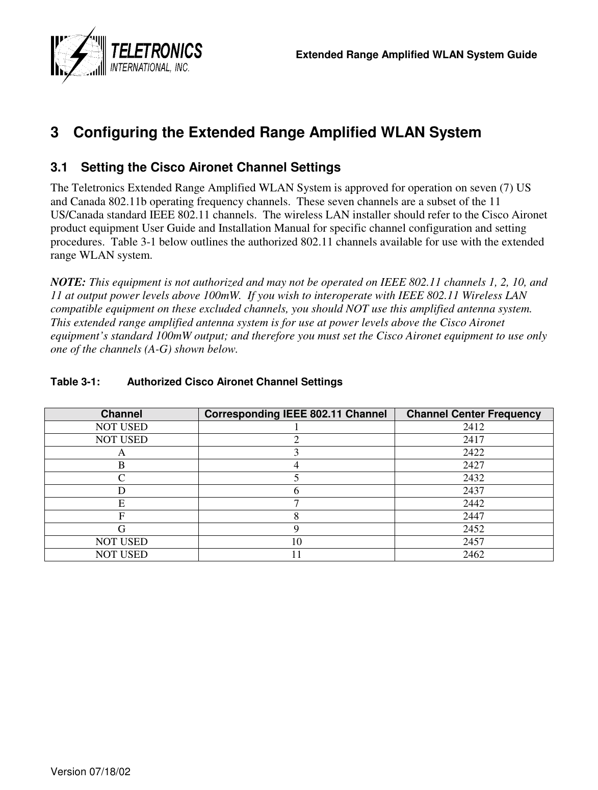
Users Manual Revised 102102

  Extended Range Amplified WLAN System Guide  Version 07/18/02          Teletronics International  Extended Range Amplified Wireless LAN System  (For Cisco Aironet 350 Series Wireless Product)    System Description, Configuration and Installation Guide         Teletronics International Inc. 1803 Research Blvd. Suite 404 Rockville, MD  20850
  Extended Range Amplified WLAN System Guide  Version 07/18/02   TABLE OF CONTENTS  1 INTRODUCTION ............................................................................................................................................5 1.1 ABOUT THIS GUIDE ...........................................................................................................................................5 1.2 WHO SHOULD USE THIS GUIDE .........................................................................................................................5 1.3 NOTES AND WARNINGS TO THE USER AND INSTALLER .....................................................................................5 1.3.1 Interference and Equipment Limits..........................................................................................................5 1.3.2 Cautions and Warnings ............................................................................................................................6 2 SYSTEM DESCRIPTION................................................................................................................................9 2.1 EXTENDED RANGE WLAN SYSTEM INFRASTRUCTURE.....................................................................................9 2.2 GENERAL DESCRIPTION.....................................................................................................................................9 2.3 SYSTEM FEATURES..........................................................................................................................................10 2.4 PLATFORM MODELS ........................................................................................................................................10 2.4.1 Wireless LAN External Amplifier .........................................................................................................11 2.4.2 Additional Wireless LAN System Components.....................................................................................13 3 CONFIGURING THE EXTENDED RANGE AMPLIFIED WLAN SYSTEM............................................14 3.1 SETTING THE CISCO AIRONET CHANNEL SETTINGS.........................................................................................14 3.2 CONFIGURING THE CISCO AIRONET RADIO UNIT ANTENNA CONNECTION PORT ............................................15 3.3 CONFIGURING THE CISCO AIRONET RADIO UNIT OUTPUT POWER SETTING ...................................................15 3.4 OTHER WIRELESS LAN SYSTEM CONFIGURATIONS........................................................................................16 4 INSTALLATION ...........................................................................................................................................16 4.1 INSTALLATION NOTES .....................................................................................................................................16 4.1.1 Primary Required Tools.........................................................................................................................16 4.1.2 Other Required Equipment.....................................................................................................................16 4.1.3 Helpful Tools and Equipment ................................................................................................................16 4.1.4 Installation Site Survey ..........................................................................................................................17 4.1.5 Installation Safety and Equipment Warnings.........................................................................................17 4.1.6 Cisco Aironet Programming and Settings..............................................................................................18 4.1.7 Antenna Installation ...............................................................................................................................18 4.2 INSTALLING THE EXTENDED RANGE (AMPLIFIED) WLAN SYSTEM................................................................18 4.2.1 Installing and Cabling the Antenna and Amplifier Unit.........................................................................19 4.2.2 Installing and Connecting the Cisco Aironet 350 Series Radio Device .................................................20 4.2.3 Installing and Positioning of Antenna....................................................................................................20 5 POST INSTALLATION TESTING...............................................................................................................21 5.1 BASIC SYSTEM OPERATIONAL CHECKS ...........................................................................................................21 5.2 WLAN SYSTEM DIAGNOSTICS........................................................................................................................22  APPENDIX INDEX APPENDIX A   ACRONYM LIST............................................................................................................23 APPENDIX B   WIRELESS.......................................................................................................................24
  Extended Range Amplified WLAN System Guide  Version 07/18/02     TABLE INDEX  Table 1-1:  Maximum Permissible Exposure Distance For 1 W Amplifier and Antenna Type.............................7 Table 1-2:  Maximum Permissible Exposure Distance For 500 mW amplifier and Antenna Type.......................8 Table 2-1:  1-Watt SmartAmp Power Amplifier Specifications..........................................................................12 Table 2-2:  500 mW SmartAmp Power Amplifier Specifications .......................................................................12 Table 3-1:  Authorized Cisco Aironet Channel Settings......................................................................................14
  Extended Range Amplified WLAN System Guide  Version 07/18/02   1 Introduction 1.1  About this Guide This guide provides a system technical description and generalized overview of the Teletronics Extended Range Amplified WLAN System engineered for exclusive use with the Cisco Aironet 350 Series Wireless product.  It also sets forth the mandatory technical parameters, installation specifics, warnings, and configuration steps necessary for professional wireless system installation.  Adherence to the installation parameters set forth in this guide is essential for compliance with current FCC rules, regulations, and FCC grants received by Teletronics International for FCC ID: MFM SAMP24Wand FCC ID: MFM SAMP24S.  It is not the intention of this guide to describe all the necessary installation facets for a complete wireless LAN and antenna system installation.  Installation details such as the mounting of the wireless LAN radio hardware, network cabling, antenna cabling, antenna mast/tower installation, and/or antenna grounding systems should be referred to a professional WLAN system installer.  This guide is specific only to the use of the Teletronics Extended Range Amplified WLAN System, and the equipment configuration parameters necessary for properly installing the system within the overall wireless LAN system.  This installation guide is included with each Teletronics Extended Range Amplified WLAN System and it is intended to supplement the Cisco Aironet product and other equipment manufacturer User and Installation Guides included within the WLAN system for the individual system components.  This Installation Guide is intended for use by the professional wireless LAN system installer.  1.2  Who Should Use this Guide Installation of the Teletronics Extended Range Amplified WLAN System should be accomplished only by a qualified wireless LAN system installer who is: •  Knowledgeable of the use, installation and configuration procedures for the Cisco Aironet 350 Series Wireless product line and associated networking components. •  Knowledgeable of each system component’s equipment User and Installation Guide.  •  Knowledgeable of the installation and configuration procedures for the site’s network infrastructure system and wiring. •  Knowledgeable of the installation procedures, safety, and code requirements for the site’s antenna, antenna mast, antenna cabling, and installation. Teletronics highly recommends that the antenna installation be performed by a qualified antenna installation professional. 1.3  Notes and Warnings to the User and Installer 1.3.1  Interference and Equipment Limits This equipment is to be operated in compliance with the limits of Part 15 of the Federal Communications Commission (FCC) Rules.  As such, operation of this equipment may not cause harmful interference, and this equipment must accept any interference received, including interference that may cause undesired performance.
  Extended Range Amplified WLAN System Guide  Version 07/18/02    FCC Part 15 rules and specifications are designed to limit harmful interference in a residential and commercial installation.  This equipment generates, uses, and can radiate radio frequency energy.  This equipment may cause harmful interference to radio communications if not installed and operated according to the instructions provided in this manual.  Proper installation and operation is no guarantee against interference.  If interference to radio or television reception is noticed, turn this equipment off and on to determine if this equipment is causing the interference.  If so, the installer/user is encouraged to attempt to correct the problem using any of the following measures:  •  Change antenna position and/or orientation. •  Provide more separation between the equipment and receiver. •  Ensure the equipment is not connected to the same circuit (power) as the receiver. •  Reduce the radio transmitter power output level. •  Consult with your professional wireless system installer for interference mitigation.  This device must not be colocated with any other antenna or transmitters.  NOTE: Any changes or modifications of the equipment not expressly approved by Teletronics could void the WLAN system grant of operation and void the authority of the user to operate the equipment.  1.3.2  Cautions and Warnings  CAUTION: The radiated output power of this product meets with FCC radio frequency (RF) exposure limits.  However, this equipment should be used in such a manner as to minimize the potential for human exposure.  Table 1-1 and Table 1-2 below address the Maximum Permissible Exposure (MPE) distances that must be maintained for each extended range amplified WLAN system model and antenna type.
  Extended Range Amplified WLAN System Guide  Version 07/18/02   Table 1-1:  Maximum Permissible Exposure Distance For 1 W Amplifier and Antenna Types Antenna Part #     (Antenna Type)  Specified Antenna Gain (dBi)  Maximum Cisco Aironet Radio Output Power (dBm) Maximum Amplifier Output Power (dBm) Minimum Cable Length (dB loss) Between Antenna & Power Amplifier for LMR 600/LMR 400 Maximum Extended Range WLAN System EIRP (dBm) Maximum Permissible Exposure (MPE) Distance           cm (inches) ANT-O2412 (Omni directional)  12  100mW (+20dBm)  1 Watt (+30dBm)  150’/98’ (6.6 dB)  35  20cm (7.9 inches) ANT-O2409 (Omni directional)  9  100mW (+20dBm)  1 Watt (+30dBm)  113’/74’ (5.0 dB)  34  20cm (7.9 inches) ANT-O2408 (Omni directional)  8  100mW (+20dBm)  1 Watt (+30dBm)  100’/65’ (4.4 dB)  34  20cm (7.9 inches) ANT-P2419 (Patch)  19  100mW (+20dBm)  1 Watt (+30dBm)  305’/197’ (13.4 dB)  35.8  200cm (79 inches) ANT-P2418 (Patch)  18  100mW (+20dBm)  1 Watt (+30dBm)  277’/179’ (12.2 dB)  35.8  200cm (79 inches) ANT-P2415 (Patch)  15  100mW (+20dBm)  1 Watt (+30dBm)  216’/140’ (9.5 dB)  35.7  200cm (79 inches) ANT-P2413 (Patch)  13  100mW (+20dBm)  1 Watt (+30dBm)  159’/103’ (7.0 dB)  35.7  200cm (79 inches) ANT-P2412  (Patch)  12  100mW (+20dBm)  1 Watt (+30dBm)  152’/99’ (6.7 dB)  35.7  200cm (79 inches) ANT-G2418 (Grid)  18  100mW (+20dBm)  1 Watt (+30dBm)  150’/98’ (6.6 dB)  41  200cm (79 inches) ANT-G2424 (Grid)  24  100mW (+20dBm) 1 Watt (+30dBm)  250’/162 (11.0 dB)’  43  200cm (79 inches) ANT-D2421 (Dish)  20.5  100mW (+20dBm)  1 Watt (+30dBm) 150’/98’ (6.6 dB)  44  200cm (79 inches)
  Extended Range Amplified WLAN System Guide  Version 07/18/02    Table 1-2:  Maximum Permissible Exposure Distance For 500 mW amplifier and Antenna Types Antenna Part# (Antenna Type)   Specified Antenna Gain (dBi)  Maximum Cisco Aironet Radio Output Power (dBm) Maximum Amplifier Output Power (dBm) Minimum Cable Length (dB loss) Between Antenna & Power Amplifier for LMR 600/LMR 400 Maximum Extended Range WLAN System EIRP (dBm) Maximum Permissible Exposure (MPE) Distance cm  (inches) ANT-O2412 (Omni directional) 12  100mW (+20dBm)  500 mW (+27dBm)  150’ /98’ (6.6 dB)  32.4  20cm (7.9 inches) ANT-O2409 (Omni directional)  9  100mW (+20dBm)  500 mW (+27dBm)  75’/49’ (3.3 dB)  32.7  20cm (7.9 inches) ANT-O2408 (Omni directional)  8  100mW (+20dBm)  500 mW (+27dBm) 50’ /33’ (2.2 dB)  32.8  20cm (7.9 inches) ANT-P2419 (Patch)  19  100mW (+20dBm)  500 mW (+27dBm)  300’/195’ (13.2 dB)  32.8  200cm (79 inches) ANT-P2418 (Patch)  18  100mW (+20dBm)  500 mW (+27dBm)  265’/172’ (11.7 dB)  33.3  200cm (79 inches) ANT-P2415 (Patch)  15  100mW (+20dBm)  500 mW (+27dBm)  157’/102’ (6.9 dB)  35.1  200cm (79 inches) ANT-P2413 (Patch)  13  100mW (+20dBm)  500 mW (+27dBm)  95’/62’ (4.2 dB)  35.8  200cm (79 inches) ANT-P2412 (Patch)  12  100mW (+20dBm)  500 mW (+27dBm)  73’/47’ (3.2 dB)  35.8  200cm (79 inches) ANT-G2418 (Grid)  18  100mW (+20dBm)  500 mW (+27dBm) 250’/162’ (11.0 dB)  34  200cm (79 inches) ANT-G2424 (Grid)  24  100mW (+20dBm)  500 mW (+27dBm)  300’/195’ (13.2 dB)  37.8  200cm (79 inches) ANT-D2421 (Dish)  20.5  100mW (+20dBm)  500 mW (+27dBm) 100’/65’ (4.4 dB)  43.1  200cm (79 inches)
  Extended Range Amplified WLAN System Guide  Version 07/18/02     WARNING: When using the Teletronics Extended Range Amplified WLAN System in the United States (or where FCC rules apply), it is the responsibility of the professional installer to ensure that only the configurations shown in Table 1-1 and Table 1-2 above and elsewhere described in this manual are used.  The use of any other configuration other than those listed herein is expressly forbidden in accordance with FCC rules CFR47 part 15.204.   WARNING: It is the responsibility of the professional installer to ensure that the system is used exclusively for fixed, point-to-point operations.  Teletronics International is not responsible for any interference caused by unauthorized modification or configuration programming of this device, or the substitution or attachment of antennas and equipment other than that specified by Teletronics International. 2 System Description 2.1  Extended Range WLAN System Infrastructure The Teletronics Extended Range Amplified WLAN System consists principally of installing wireless LAN Access Points (APs) or WLAN cards with an extended range (amplified) system at a customer chosen site that have traditional wired network access (T-1, Fiber, or other medium) connectivity.  When used in conjunction with the site’s “wired-to-wireless” infrastructure, the extended range WLAN system will essentially extend the WAN fixed site infrastructure within the chosen area wirelessly to any mobile wireless client card and/or to other Extended range AP/Bridge fixed sites operating within the wireless cell range (zone) of that site.   2.2 General Description The Teletronics Extended Range Amplified Wireless LAN System is designed to be used strictly with the system-included Cisco Aironet 350 Series Wireless product for offering Direct Sequence Spread Spectrum (DSSS) wireless transceiver operation at the 11 Mbps data rate.  It fully supports wireless system connectivity and performance compatibility as described by the IEEE 802.11b specification.  This product allows for a high-performance extended range system capability to be employed for supporting a mobile wireless client unit communicating back to an Access Point/Bridge unit at a fixed site station, or to allow for extended wireless communications between point-to-point, or point-to-multipoint Access Point/Bridge fixed sites. The fixed site WLAN amplified system provides for a significantly improved operating range of the wireless network infrastructure.  The amplified WLAN system contains and is authorized for use only with the Cisco Systems Aironet 350 Series Wireless product line that incorporates the Cisco Aironet LMC-350 radio module.  This product line currently includes the following Cisco Aironet 350 Series* products:
  Extended Range Amplified WLAN System Guide  Version 07/18/02   •  Access Point unit (AIR-AP352E2R); •  Multifunction Bridge unit (AIR-BR350)  *  The above listed Cisco Aironet 350 Series products when used separately from the Teletronics Extended Range Amplified WLAN System are covered under an FCC Grant of Authorization and Compliance under the manufacturer Cisco Systems, Inc., FCC ID: LDK102040. 2.3 System Features The Teletronics Extended Range Amplified WLAN System offers the following state-of-the-art features and capabilities:  •  Industry Leading Cisco Aironet 350 Series Wireless Radio Unit* - Access Point; or Bridge unit (*per the system model radio features ordered). •  IEEE 802.11b Wireless LAN 2.4 GHz Radio System Compatibility. •  7 available channels in US/Canada – (Standard 802.11b US/Canada channels 1, 2, 10, and 11 are FCC prohibited from use with an amplified system operating above 100mW). •  Bi-Directional WLAN Linear Amplification with Built-in Ultra Low Noise Pre-amplifier for providing reliable, long range WLAN radio link operation. •  Auto-ranging Amplifier Input Drive Level feature for compensating for feed line losses and yielding maximized fixed RF output power to the antenna. •  Low Loss DC Power Injector to allow voltage feed via the antenna coaxial cable; therefore allowing the weatherproof main amplifier unit to be remote mounted near the antenna for minimized PA to Antenna cable loss in fixed site installations. •  Variable Length Radio-to-DC Injector and Power Amplifier feed line cabling for flexible and easy antenna system installations. •  Customized Power Amplifier-to-Antenna Cable for low loss and installation unique lengths. •  Limited one year warranty. 2.4 Platform Models The Teletronics Extended Range Amplified Wireless LAN System is available in two platform models – 1 W outdoor amplifier system and a 500 mW outdoor amplifier system.  Each platform model is further available in different antenna gain configurations and appropriate minimum cable length for best meeting a system installation’s particular coverage concerns.
  Extended Range Amplified WLAN System Guide  Version 07/18/02    The Teletronics Extended Range Amplified Wireless LAN System configurations available for use with the Cisco Aironet 350 Series Wireless products are:  •  1 W outdoor amplifier system:  o  12dBi Omni directional  o  9dBi Omni directional  o  8dBi Omni directional  o  19dBi Patch  o  18dBi Patch  o  15dBi Patch  o  12dBi Patch  o  24dBi Grid  o  18dBi Grid  o  20.5dBi Dish  •  500 mW outdoor amplifier system:  o  12dBi Omni directional  o  9dBi Omni directional  o  8dBi Omni directional  o  19dBi Patch  o  18dBi Patch  o  15dBi Patch  o  12dBi Patch  o  24dBi Grid  o  18dBi Grid  o  20.5dBi Dish  2.4.1  Wireless LAN External Amplifier Each of the Teletronics Extended Range Amplified WLAN Systems described above uses the Teletronics International, Inc. Smart Amplifier (SmartAmp) Bi-directional Power Amplifier 2.4 GHz version.  The system will incorporate either the outdoor model 1-Watt AGC Amplifier or the 500 mW model AGC outdoor amplifier with appropriate transmission line cabling lengths, and high gain antennas for a complete fixed site system installation.     Both of the Teletronics SmartAmp 2.4 GHz amplifier models feature an auto ranging input RF drive level capability which allows the amplifier to automatically determine the input RF level received from the Cisco Aironet transceiver equipment and set its internal power gain to yield the full-programmed RF output level.  This auto ranging feature eliminates the necessity for (and inherent errors in) calculating feed line losses between the data transceiver (Cisco radio card/unit) and the main amplifier unit.  The auto ranging feature of the amplifier allows for variable installations to be handled with greater ease and flexibility for feed line cable lengths and routing concerns.  However, it is important that each systems-specified minimum transmission cable lengths (dB loss) between the main amplifier unit and antenna are maintained for power compliance to FCC EIRP specifications.
  Extended Range Amplified WLAN System Guide  Version 07/18/02    The SmartAmp power amplifier specifications and input drive level for desired output power levels are specified in Tables 2-1 and 2-2 for each different power output model below:  Table 2-1:  1-Watt SmartAmp Power Amplifier Specifications  Operating Range  2400 ~ 2500 MHz Operating Mode  Bi-directional TDD Transmit Output Power  +30 dBm (1 Watt) Transmit Input Power  9 dB min, 23 dB max Transmit Gain  Automatically adjusts up to 27dB Receive Gain  17 dB Frequency Flatness  ±1.0 dB Noise Figure  3.5 dB Lightening Protection  Direct DC ground at antenna port DC Surge Protection  At 12 V DC input LED indicators on Amp  Tx: Green, Rx: Red Operating Temperature  -40 °C ~ + 75 °C Power Supply  12 V DC at 1.1 Amp RF Connector  Type N, Female  Table 2-2:  500 mW SmartAmp Power Amplifier Specifications  Operating Range  2400 – 2500MHz Operating mode  Bi-directional TDD Transmit Output Power  +27dBm (500mW)  Transmit Input Power  0 dBm min, 23 dBm max Transmit Gain  Automatically adjusts up to 26dB  Receive Gain  14 dB Frequency Flatness  +/- 1.0 dB Noise Figure  3.5 dB Lightning Protection  Direct DC ground at Antenna port DC Surge Protection  At 12 VDC input LED Indicators  Tx: Green, Rx: Red Operating Temperature  -20 C ~ 70 C Power Supply  12 VDC at 0.7 amps Connectors  Type N, Female    CAUTION: The configured output power for the Cisco Aironet device sets the maximum expected input drive level to the external power amplifier.  Therefore, it is essential that the Cisco Aironet device be configured for an output power level consistent with the charted input drive values stated in Tables 2-1 and 2-2 above with respect to the power amplifier specifications and feed line cable losses.
  Extended Range Amplified WLAN System Guide  Version 07/18/02   The unit can be used in combination with different types of cables as listed in the following table. The length of the cable between the amplifier and the antenna should respect the cable loss listed in Table 1-1 for the 1 W amplifier, and Table 1-2 for the 500 mW amplifier, in order to maintain FCC compliance.  Table 2-3:  Nominal Loss Characteristics for Different Cables  Nominal Loss Characteristics For Different Cables (Decibels per hundred feet at 2.5 GHz) LMR-400 LMR-500 LMR-600 LMR-900  LMR-1200 6.8 dB 5.5 dB 4.4 dB 3.0 dB  2.3 dB 2.4.2  Additional Wireless LAN System Components The wireless LAN integration company/installer will be responsible for providing any additional site WLAN system equipment, engineering, and installation services to include providing for:  •  Site Survey Engineering & Design; •  Antenna Mast Assemblies; •  Antenna System Grounding; and •  Professional installation services per this Extended Range Amplified WLAN System Installation Guide and the system component equipment manufacturer User Guide and Installation Manuals.
  Extended Range Amplified WLAN System Guide  Version 07/18/02    3  Configuring the Extended Range Amplified WLAN System 3.1  Setting the Cisco Aironet Channel Settings The Teletronics Extended Range Amplified WLAN System is approved for operation on seven (7) US and Canada 802.11b operating frequency channels.  These seven channels are a subset of the 11 US/Canada standard IEEE 802.11 channels.  The wireless LAN installer should refer to the Cisco Aironet product equipment User Guide and Installation Manual for specific channel configuration and setting procedures.  Table 3-1 below outlines the authorized 802.11 channels available for use with the extended range WLAN system.  NOTE: This equipment is not authorized and may not be operated on IEEE 802.11 channels 1, 2, 10, and 11 at output power levels above 100mW.  If you wish to interoperate with IEEE 802.11 Wireless LAN compatible equipment on these excluded channels, you should NOT use this amplified antenna system.  This extended range amplified antenna system is for use at power levels above the Cisco Aironet equipment’s standard 100mW output; and therefore you must set the Cisco Aironet equipment to use only one of the channels (A-G) shown below.  Table 3-1:  Authorized Cisco Aironet Channel Settings  Channel  Corresponding IEEE 802.11 Channel  Channel Center Frequency NOT USED  1  2412 NOT USED  2  2417 A 3 2422 B 4 2427 C 5 2432 D 6 2437 E 7 2442 F 8 2447 G 9 2452 NOT USED  10  2457 NOT USED  11  2462
  Extended Range Amplified WLAN System Guide  Version 07/18/02    3.2  Configuring the Cisco Aironet Radio Unit Antenna Connection Port The Teletronics Extended Range Amplified WLAN Antenna System can only be used with the Cisco Aironet 350 Series wireless products that are designed for use with an external antenna connection capability.  Specifically, these Cisco Aironet 350 Series products include the AIR-AP352E2R Access Point unit, and the AIR-BR350Bridge units.    These particular Cisco Aironet units are each outfitted with two external antenna connection ports.  Each of the radio unit’s antenna connection ports are uniquely designed for use with either the Reverse-Polarity-TNC male connector, such as in the case of the Access Point, and Bridge..  The WLAN system will include a matching Cisco Aironet radio-to-DC Injector connecting cable for use in connecting the antenna system to each kit’s (ordered) Cisco Aironet radio component.   The Cisco Aironet 350 Series product manages its “in use” antenna connection ports via software configuration control over the left and right antenna ports based upon enabling or disabling the left or right antenna port, or enabling or disabling the receive diversity function (disables the left antenna).  The Cisco Aironet radio unit must be configured to use the right or primary antenna connection port as the primary or sole transmit/receive antenna connection port.  The unit’s left antenna connection should be configured as disabled (or diversity off), unless a Receive Diversity antenna is to be used within the particular system installation.  In all installations, the primary/right (transmit & receive) antenna connection port will be used as the point of attachment for the extended range amplified system.  The wireless LAN installer should refer to the Cisco Aironet product equipment User Guide and Installation Manual for reviewing, configuring, and setting the antenna connection port parameters.   3.3  Configuring The Cisco Aironet Radio Unit Output Power Setting The Teletronics Extended Range Amplified WLAN System is approved for operation with the Cisco Aironet 350 Series product at various power output levels specific to the power amplifier output power and the system model supporting the Cisco radio unit.  Section 2.4 lists the Cisco Aironet radio unit power settings per system amplifier and antenna gain authorized for use.  The power output specifications, cable lengths, and antenna gains listed within Tables 1-1 and 1-2 must be adhered to with respect to the Teletronics Extended Range Amplified WLAN System model being installed.
  Extended Range Amplified WLAN System Guide  Version 07/18/02    The wireless LAN installer should refer directly to the Cisco Aironet product equipment User Guide and Installation Manual for proper configuration procedures in setting the required Cisco radio unit output power level.    Warning:  Operating the Cisco Aironet equipment with Power Amplifier power levels, cable length and/or antenna gains in variance to the WLAN system specifications shown in Tables 1-1 and 1-2 is prohibited and may exceed authorized FCC RF power level specifications.  3.4  Other Wireless LAN System Configurations Any questions related to additional wireless LAN system component parameter configurations such as Cisco Aironet radio unit network SSID and IP assignment; WEP encryption codes, protocol filtering, etc. should be referred to the specific equipment User Guide for proper configuration procedures and settings. 4 Installation 4.1 Installation Notes 4.1.1  Primary Required Tools •  User guides and installation manuals for all equipment •  Assorted open-end and/or adjustable wrenches •  Antenna cable clamps and/or cable hanging kits •  Wire cutter/stripper •  Cable connector crimping tool •  Screwdriver set – cross tip and flathead •  Pliers 4.1.2  Other Required Equipment •  Suitable Antenna Mast Assembly; or •  Tower hardware •  Antenna Grounding Kit 4.1.3  Helpful Tools and Equipment •  Cellular telephones or walkie-talkies •  Binoculars •  Compass •  Leveling tool •  Handheld GPS •  Ladder
  Extended Range Amplified WLAN System Guide  Version 07/18/02    4.1.4  Installation Site Survey Prior to installing the Extended Range Amplified WLAN System, the site platform targeted for installation must be surveyed for engineering design and installation.  Adherence to Maximum Permissible Exposure (MPE) RF Radiation Hazard distances must be reviewed and antenna locations planned for minimizing potential RF energy human exposure levels to personnel working in the vicinity of the amplified antenna location, as well as minimizing any potential co-site radio interference issues.  During fixed site WLAN surveys and analysis, emphasis should also be placed on locating the antenna in a position that is free of obstructions near the antenna location.  Such obstructions include large trees, air conditioning units, other antenna masts, chimneys, retaining walls, and so forth, as they can significantly affect the LOS range of the WLAN system.  The site survey and resulting plan should take all these elements into consideration.  The fixed site antenna should be mounted as high as possible.  The antenna mast should place the antenna at least 10 to 15 feet above the rooftop or above any obstruction obstructing the antenna’s line of sight (LOS) signal path.  A note should be made of the antennas position, required mast height, and the type of mounting hardware needed.  Antenna-to-Antenna Mast U-bolt mounting hardware is shipped with the Extended Range Amplified WLAN System and should meet the requirements for most types of mast installation.  The means for communicating with helpers at the antenna site while conducting link testing should also be planned in advance.  For instance, walkie-talkies or cellular phones would be very helpful during this procedure.  Any necessary routing for the feed line antenna cable must be determined.  If the cable extends through the roof or wall, appropriate waterproof fittings and/or conduit paths must be used.  A licensed antenna specialist or roofing contractor should be consulted to assist with proper cable routing and antenna installation specifics, as necessary.  Electrical power considerations for fixed site installations must be made in advance for properly installing the extended range antenna system.    4.1.5  Installation Safety and Equipment Warnings NOTE:  Only experienced antenna installers who are familiar with local building and safety codes, and have been licensed by the appropriate government regulatory bodies wherever necessary, shall install the antenna system.  Failure to do so may void the product warranty, as well as expose the end-user to legal and/or financial liabilities.  Teletronics International Inc., its agents, resellers, or distributors, are not liable for injury, damage, or violation of government regulations that may arise from failing to comply with the guidelines described in this document.
  Extended Range Amplified WLAN System Guide  Version 07/18/02     WARNING: Before performing any of the following steps, ensure there are no power lines within 50 feet of the installation site.  If a mast should fall during installation or during operation, contact with any power line may result in fire and can be fatal.   WARNING PATCH & OMNI ANTENNAS: The Teletronics Extended Range Amplified WLAN Systems are designed for antenna mounting in open areas such as on rooftops or building interior or exterior walls.  The antenna should be installed with at least 20 centimeters clearance from areas generally occupied by people over an extended period of time (>30 minutes).   WARNING DISH & GRID ANTENNAS: The Teletronics Extended Range Amplified WLAN Systems are designed for antenna mounting in open areas such as on rooftops or building exterior walls.  The antenna should be installed with at least 2 meters clearance from areas generally occupied by people over an extended period of time (>30 minutes).    WARNING: Never use a power supply other than the one shipped with the system.  Doing so may cause damage to the radio and/or the amplifier.  4.1.6  Cisco Aironet Programming and Settings The Cisco Aironet radio device should be verified or configured for its designated output power setting prior to fix mounting the Cisco radio unit and main amplifier unit to a fixed site antenna mast. 4.1.7  Antenna Installation  Detailing a specific fixed site mast mount antenna installation procedure is beyond the scope of this installation guide as the WLAN system installation can vary from site to site.  The wireless system installer should be fully knowledgeable of the installation procedures, safety, and code requirements for installing the particular fixed site WLAN system antenna, antenna mast assembly, antenna cabling and grounding requirements for an installation.  Teletronics highly recommends that the Extended Range Amplified WLAN System be installed only by a qualified antenna installation professional that is familiar with vehicular fixed site WLAN system installations.  The antennas contained within each Extended Range Amplified WLAN System are designed for mounting on the appropriate kit platform.  Each extended range WLAN system includes the necessary antenna hardware pertinent for mounting the antenna on the platform designated by the kit type.  However, additional necessary site-specific antenna mast/tower assemblies, guide lines, grounding wire/kits, cable ties, etc. are not provided within the Extended Range Amplified WLAN system; and therefore, these items as necessary for a particular installation will need to be provided by the WLAN system installer. 4.2  Installing the Extended Range (Amplified) WLAN System Different model extended range amplified WLAN systems for fixed platform sites will have different mounting requirements and different installation mechanics/procedures based upon the building/site facilities.  The following instructions provide for a generalized procedure for installing and cabling the fixed site extended range WLAN system.
  Extended Range Amplified WLAN System Guide  Version 07/18/02    4.2.1  Installing and Cabling the Antenna and Amplifier Unit The steps listed below are applicable for the Fixed Site Extended Range Amplified WLAN System.  •  Attach the (installer provided) antenna mast assembly and mounting hardware to a solid structure on the building (i.e., the roof top, concrete bulkhead, vent pipe, etc.). •  Using the kit-included mounting hardware, secure the fixed site antenna to the top section of the antenna mast assembly. •  Attach the kit-included Teletronics SmartAmp main (remote) amplifier unit directly beneath the antenna element assembly using the U-bolts provided.  The distance below the antenna should be approximately 12 – 14 inches based upon maintaining an adequate feed line cable loop between the devices.  •  Connect one end (N-Male connector) of the kit-included PA-to-Antenna RF cable assembly (minimum length listed in Table 1-1 and Table 1-2 for LMR 600 and LMR 400 type cable) to the antenna (N-Female) connector and connect the other end of the LMR cable assembly (N-Male) to the SmartAmp amplifier unit’s (N-Female) connector labeled ANTENNA on the amplifier. •  Connect one end of the kit-included DC-Injector-to-PA (feed line) RF cable assembly (minimum 3 feet LMR 600 or LMR 400) to the SmartAmp main amplifier unit (N-Female) connector labeled DC-INJECTOR on the amplifier.  •  Apply weather sealant tape around all cable connections made at the antenna and the power amplifier.  Wrap the entire connection, overlapping each layer slightly to ensure a weather-tight seal.  This will prevent corrosion of the connections by the weather. •  Connect a suitable grounding cable or grounding kit (installer provided) between the antenna mast assembly and the building ground, to ground the antenna system. •  Tie down the antenna RF cable assembly to the mast every six to twelve inches using plastic tie wraps or other cable hanging kit tools and carefully raise the antenna mast.  Loosely secure it with the mounting hardware.  •  Using a leveling tool, ensure the antenna mast assembly and most importantly the omni-directional antenna element are positioned vertically for best omni-directional beam and pattern performance. For the point-to-point antenna, the antenna should be oriented in such a way as to provide LOS, in order to achieve the maximum performance. •  Securely tighten the mast mounting bolts/screws.  •  Route the amplifier feed line RF cable assembly via appropriate cable access conduit and pre-installation routing plan to the equipment room or equipment enclosure box that will house the Cisco Aironet AP radio unit, Main Amplifier unit, and the power amplifier DC-Injector module (i.e., Telco room, network closet, or outdoor enclosure box).  •  Place and mount the kit-included DC Power Injector module and module Power Supply within the equipment room/enclosure near the Cisco Aironet radio unit.  Position the module unit so that the LED indicators are easily visible to the installer for operational condition indication and/or visual troubleshooting diagnosis.   •  Plug the DC-Injector Power Supply module’s DC-In male connector into the Injector module’s DC-In female jack and then plug the power supply unit into the building AC power source.  It is recommended that a commercially available surge protector power strip be used for the AC connections.  Check for a green light on the DC-Injector LED for power being applied.
  Extended Range Amplified WLAN System Guide  Version 07/18/02   4.2.2  Installing and Connecting the Cisco Aironet 350 Series Radio Device  The installation method used for installing the Cisco Aironet device (i.e. 350 Series Access Point or Bridge unit) depends upon the site facility to be fitted with the device.  The WLAN installer is directed to follow the basic hardware mounting and installation instructions described within the product’s User Guide and Installation Manual.  Generalized Cisco Aironet radio component to amplifier and antenna cabling connections are described below:  •  Mount the Cisco Aironet radio device per the product’s User Guide and Installation Manual. •  Attach the RP-TNC Male end of the kit-included Cisco Radio-to-DC-Injector RF Cable Assembly (feed line cable) to the “Right/Primary” labeled external antenna connector port      (RP-TNC Female) on the rear of the Cisco Aironet radio unit and securely tighten. •  Attach the cable’s other connector end (N-Male) to the N-Female connector labeled RADIO on the amplifier DC-Injector module and securely tighten.  Note: Certain installations may require the use of a Cisco Radio-to-DC Injector Adapter Connector (RP-TNC Male-to-N-Male) in substitution of the Cisco Radio-to-DC Injector RF Cable Assembly, to allow for a direct connection of the DC Injector module to the Cisco radio external antenna connection port. •  Connect an Ethernet (CAT 5) cable to the Ethernet connection port on the rear of the Cisco Aironet radio device labeled “Inline Power Ethernet.” •  Route the Ethernet cable (as required) from the physical Cisco Aironet (AP/Bridge) unit’s location to the appropriate network data source location (i.e. Telco room, network closet, or power room, etc.).  Note: The Cisco Aironet 350 Series wireless Access Point or Bridge is powered remotely by utilizing a Power-over-Ethernet (POE) module (AIR-PWRINJ). •  Connect the near end CAT 5 Ethernet cable connection into the POE Module’s port labeled     “To AP/Bridge.”  Note: Internally the POE module applies the required operating DC voltage for the Cisco Aironet radio onto the Ethernet (CAT 5) cable’s unused wire pairs. •  Position the POE power injector (as required) and connect/power the module’s AC power cord into an AC power source.  It is recommended that a commercially available surge protector power strip be used for the AC connections. •  Make an Ethernet network cable connection coming from the wired network switch, hub, or router device to the POE module’s Ethernet (CAT 5) connection port labeled “To Network.” •  Configure the necessary Cisco Aironet and/or network system parameters and test the installed extended range WLAN system.  4.2.3  Installing and Positioning of Antenna Antennas direct Radio Frequency (RF) power into a coverage area.  The antennas listed in Table 1-1 and Table 1-2 are different based on their coverage patterns.  The correct antenna for a site is chosen by determining the antenna that provides the optimum coverage pattern.  Knowing the environment would help to determine the right antenna and placement.
  Extended Range Amplified WLAN System Guide  Version 07/18/02    Table 1-1 and Table 1-2 list the following antenna types:  •  Omni-directional antennas have a 360-degree coverage pattern on a horizontal plane for multipoint and mobile applications where wide coverage is desired. •  Directional antennas (Patch, Grid, Dish) concentrate the coverage pattern in one direction.  This produces a conical-shaped main lobe.  The antenna directionality is specified by the angle of the beam width.  Typical beam width angles are from 90 degrees (somewhat directional), to as little as 20 degrees (very directional).  The directed beam allows for a longer but narrower coverage pattern, which is ideal for elongated areas, corners, and outdoor point-to-point applications. Calculating Range: For an unobstructed outdoor site, each 1dB increase in gain results in a range increase of approximately 5%.  The coverage pattern may vary depending on the amount and type of obstructions at the site.  Positioning antennas: The proper positioning (orientation) of antennas at a site helps ensure the maximum coverage area.  Antenna should generally be mounted as high and as clear of obstructions as practically possible.  Best performance is attained when both transmitting and receiving antenna are located at the same height and in a direct line of sight of each other.  Access Points should be positioned on or close to the ceiling.  Place omni-directional antennas in the center of the coverage area when possible.  When ceiling mounted, try to keep antennas at least two feet from sprinkler heads, metal lighting fixtures, etc.  For directional antennas, point at the direction of the coverage area.  All antenna characteristics are the same for both transmit and receive.  For outdoor mounting of antennas note that the coaxial RF cable should be kept as short as possible to minimize RF loss - the length of cable that comes with the antenna is optimized.  Use coaxial cable extensions if needed, available on our accessories page - however, placing the Access Point close to the antenna and bringing the Ethernet cable to the Access Point is preferred.  Please review the variety of optional antennas that are available at Accessories and Spare Parts.  Teletronics offers several omni-directional and directional antenna to provide for optimum coverage and performance.  5  Post Installation Testing 5.1  Basic System Operational Checks Basic system operational checks are performed using the system diagnostic LED indicators on the Cisco Aironet and DC Injector module devices.  Power on the fixed site network, and all wireless LAN system devices and verify the following:
  Extended Range Amplified WLAN System Guide  Version 07/18/02     1.  Power is being applied to the Cisco Aironet wireless radio components. 2.  Ethernet Activity is being indicated by the Cisco Aironet radio unit Indicator Light. 3.  AP or Client association status is being indicated by the Cisco Aironet radio unit Association Status Indicator Light. 4.  The Cisco Aironet radio unit Radio Activity Indicator Light is indicating radio activity.  NOTE: If any of the above conditions are not being met – the installer should refer to the specific Cisco Aironet product user guide for troubleshooting the Cisco Aironet equipment.  5.  Power is being provided to the DC Injector module– the LED indicator is illuminated green. 6.  Amplifier is in receive data mode – the bi-color LED indicator is illuminated red. 7.  Amplifier is in transmit data mode – the bi-color LED indicator is illuminated green. 8.  Amplifier is processing high-speed (Tx/Rx) data – the bi-color LED indicator is orange, similar to the Cisco Radio Activity Indicator light flashing.  NOTE: In bright sunlight, the LED indicators may be difficult to see.  5.2  WLAN System Diagnostics It is highly recommended that the WLAN system installer run appropriate WLAN system diagnostics and network link quality, range, and throughput measurement tests to ensure optimal extended range (amplified) WLAN antenna system performance is being achieved.
  Extended Range Amplified WLAN System Guide  Version 07/18/02    APPENDIX A:  ACRONYM LIST  AP Access Point DSSS  Direct Sequence Spread-Spectrum FCC  Federal Communications Commission IEEE  Institute of Electrical and Electronic Engineers IEEE 802.11  IEEE standard for wireless LANs IT Information Technology LAN  Local Area Network LED  Light Emitting Diode LOS Line-of-sight PCMCIA  Personal Computer Memory Card International Association RF Radio Frequency SmartAmp  Teletronics Smart Amplifier WLAN Wireless LAN
  Extended Range Amplified WLAN System Guide  Version 07/18/02   APPENDIX B:  WIRELESS OVERVIEW IEEE 802.11b Overview  Since the early 1970’s, the basic technology has been in place for LANs to blossom in both the public and private sectors.  Standard LAN protocols, such as Ethernet, operate at relatively high speeds using inexpensive connection hardware to bring digital networking to almost any computer.  Until recently however, LANs were limited to the physical, hard-wired infrastructure of the building.  Even with phone dial-ups, network nodes were limited to access through wired, landline connections.  The major motivation for and benefit of wireless LANs is increased mobility.  Simply stated, the architecture employed uses fixed network Access Points (APs), which are capable of communicating with mobile nodes.  The network APs are then connected via landlines to widen the LAN's capability by bridging wireless nodes to other, wired nodes.  By overlapping the service areas, handoffs can be made to occur.  This structure is very similar to the present day cellular networks around the world.  The Institute of Electrical and Electronic Engineers (IEEE) is an international body that defines standards for electrical devices.  IEEE 802.11 is the proposed standard for wireless LANs, with provisions for data rates of either 1 Mbps or 2 Mbps.  The standard encompasses Infrared (IR) Pulse Position Modulation, Frequency Hopping Spread-Spectrum (FHSS), and Direct Sequence Spread-Spectrum (DSSS) technologies.  For the two spread-spectrum technologies, IEEE 802.11 calls for operation in the 2.4 - 2.4835 GHz frequency range – an unlicensed band that the Federal Communications Commission (FCC) has authorized for industrial, scientific and medical (ISM) applications.   While the FHSS technology is limited to a throughput of 1 - 2 Mbps under the 802.11 standard, the DSSS technology operates under an enhanced version of the standard (IEEE 802.11b), which enables operation with a variable throughput capability of 1, 2, 5.5 or 11 Mbps.  The result of the much higher bandwidth afforded by employing IEEE 802.11b DSSS wireless communications is the ability to transfer much more data than is possible using IEEE 802.11 FHSS or the many other radio frequency (RF) data communications media operating in the 400, 450, 800, and 900 MHz frequency bands.  This greater bandwidth finally permits the implementation of dynamic, highly mobile, wireless LANs capable of data throughput and performance characteristics comparable to that found in typical wired networks.   It must be noted, however, that there are significant limitations associated with the IEEE 802.11b technology.  First, the higher operating frequencies result in an inherently shorter communication range for a given RF power output.  Second, as a radio technology, it is primarily a half-duplex device – meaning that it will not transmit and receive simultaneously.  The advertised throughput speeds are raw data rates.  Due to overhead and the half-duplex nature of the device, the effective throughput speeds are generally less than half of their advertised rates.  Finally, as with most low power RF devices, optimal data throughput speeds will be achieved only when clear line-of-sight (LOS) communications can be maintained between the devices.  The FCC has limited the power output of IEEE 802.11b radio transmissions to a maximum of 1-watt peak power or not more than +36dB signal strength with any given omni-directional antenna.  Most commercial-off-the-shelf (COTS) IEEE 802.11b equipment operates at power levels well below the FCC specification.  Teletronics International has designed an Extended Range Amplified WLAN System that takes advantage of the FCC power limits by installing an amplifier within the system to achieve maximum range and quality of communications between the mobile units
  Extended Range Amplified WLAN System Guide  Version 07/18/02    and fixed sites.  The Extended Range Amplified WLAN Systems that we will be using have been certified for compliance with Part 15 of FCC regulations and are authorized for use with the proposed wireless network.  Nevertheless, it will be important to bear in mind that communication quality will largely depend on the ability to maintain clear LOS between the elements comprising the network.

Navigation menu