Teletronics SAMP24W Wireless LAN System with Amplifier User Manual SmartAmp 2 4 Ghz
Teletronics International Inc Wireless LAN System with Amplifier SmartAmp 2 4 Ghz
Contents
- 1. Amplifier Manual
- 2. Users Manual Revised 101802
Amplifier Manual

SMARTAMP TM
BI-DIRECTIONAL POWER AMPLIFIER
2.4 GHz, 1W version
User and Installation Manual
TELETRONICS INTERNATIONAL, INC.
1803 Research Blvd., Suite 404,
Rockville, Maryland, USA, 20850-3155
Email: sales@teletronics.com Web Site:
www.teletronics.com
Tel: (301)-309-8500 Fax: (301)-309-8851
SmartAmp TM is a trademark of Teletronics International Inc.

Page 1
Copyright ©2002
by
Teletronics International, Inc.
Patent Pending
All Rights Reserved. No part or parts of this document may be reproduced, translated, stored in any
electronic retrieval system, or transmitted, in any form or by any means, electronic, mechanical,
photocopying, recording, or otherwise, without the prior written permission of the copyright holder.
Page 2
Table of contents
User and Installation Manual _______________________________________________________i
1. General Product Description ____________________________________________3
2. Background _________________________________________________________3
3. Major Parameters ____________________________________________________4
4. Salient Characteristics:________________________________________________5
5. Installation: ______________________________________________________6
6. DC Power Injector Connections, Indicators and labels: ______________________6
7. Amplifier Connections, Indicators and Labels: _____________________________7
8. Functioning: ________________________________________________________7
9. Specifications: _______________________________________________________8
General Specifications ______________________________________________________ 8
Nominal Loss Characteristics For Different Cables______________________________ 9
10. LIMITED WARRANTY _____________________________________________10
Page 3
1. General Product Description
SMART Amplifier (SMARTAMP) is a new bi-directional antenna-
mount amplifier designed to match any advanced spread
spectrum system, either direct sequence or frequency
hopping, to allow the extension of the operating range in
wireless environment. It is provided in a wide range of
frequencies, such as 900 MHz, 2400 MHz, or 5800 MHz where
advanced spread spectrum systems are operated. It works in
Time-Division Duplex (TDD) mode that allows the radio device
sharing the antenna in different time intervals. SMARTAMP
consists of an intelligent algorithm and Automatic Gain
Controlled (AGC) circuits to maintain the output power and
prevent transmit signal saturation. The input transmit power
level is sensed by the Radio Frequency (RF) sensor and the
gain is automatically adjusted to minimize the signal
distortion so that the desired signal quality can be
assured.
This product has a wide range of wireless applications in
Wireless Local Area Network (WLAN), Wireless Local Loop
(WLL), Wireless Internet Access (WIA), wireless modem
connection with point-to-point, point-to-multipoint, where
the Time Division Duplex (TDD) technology is used.
2. Background
In wireless applications, when longer operating range is
required, the add-on antenna amplifier and DC injector set
are often a choice. Because of different site layout and
hardware configuration, it is almost impossible for
amplifier manufacture to design the amplifier and fit all
applications. Typically, in most applications, the
interconnection cable could have different length from a few
feet to a few hundred feet. The attenuation between DC
injector and bi-directional amplifier could be few dB to
more than 20 dB. Also, different radio modems have different
output powers. Thus, the system installer must carefully
measure the input RF power at the antenna amplifier and
specify the gain of the amplifier in order to maintain the
system performance. With different systems, different
amplifiers are required. With this invention, the major
difference as compared to other existing technology, is the
‘‘SMART function’’ - power level detection and automatic
gain control circuit. With SmartAmp, the gain can be
intelligently adapt to the input power level in a wide range
and automatically further adjusted to accommodate the cable
and connectors loss, by however length and configuration.
The output power level is monitored and maintained
intelligently, hence the desired performance can be achieved
in all hardware configurations for TDD wireless applications
irrespective of installation environment.
The table below summarizes the difference between SMARTAMP
and other TDD antenna-mount amplifier product.

Page 4
Differences Between SmartAmp and Other TDD Amplifier
SMARTAMP Other TDD Amplifier
Transmit gain Intelligent
self adjusted
Fixed
Transmit power
level
Maintained Varies, depending on
input power level
Transmit signal
distortion
Minimized at
all time
Much worse at high
input power levels
Input power range
requirements
Wide range
accepted
Designed for narrow
range only
3. Major Parameters
Smart Amplifier fitted with a Low Noise amplifier (LNA) and
together with its unique bi-directional features is fully
capable of enhancing the coverage area of 2.4 GHz radio
signals by amplifying transmitted and received signals.
The Smart Amp ensures a seamless RF link in most
installations with long cable losses. Its unique outdoor
design enables it to be mast mounted and to operate in wide
temperature range of --40 to +75 C.
2.0 mW (+3 dBm) input to the amplifier delivers 1Watt
output. For signal input values greater than 3 dBm the Smart
Amplifier attenuates the signal accordingly and keeps the
output at 30 dBm. Up to 200 mW of power may be safely
applied directly to the amplifier input without causing any
damage.
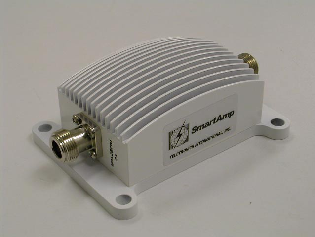
The complete set includes:
1. An outdoor unit, the SmartAmp
2. DC injector
3. Universal power supply
4. Mounting hardware.
The DC injector carries the power along with RF signal to the outdoor unit via co-
axial cable.
Page 5
4. Salient Characteristics:
• Complete One Year Warranty on parts and labor.
• Automatic gain control to minimize the signal distortion
• Wide Transmit input levels (2mW to 200mW)
• Low noise amplifier with system noise figure 3.5dB
• Universal 110/220VAC auto switching AC adapter for DC power injector
• Green LED on DC Injector for power.
• Bi-color LED on SmartAmp for transmit and receive.
• SmartAmp equipped with Lightening Protection if grounded properly.
• DC injector equipped with surge protection.
• Industry standard “N” Connectors on both ends.
• Outdoor Weatherproof enclosure.
Page 6
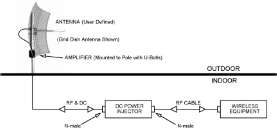
5. Installation:
The SmartAmp is a stand-alone unit designed for installation by professional radio installers.
Typical Installation:
As shown in the above diagram power is carried to the amplifier from DC Injector via RF cable.
The DC injector is an indoor unit and requires weather protection. The amplifier is installed at
the antenna pole (or mast) with the U-bolt assembly. It is a weatherproof unit and designed to
withstand the outdoor environment. Since the SmartAmp is built with lightening protection
circuitry, it is extremely important to ground the whole unit. A grounding cable can be tightened
directly to the U bolt. This would not only ground any lightening strike on the antenna but
would also relieve it from any static buildup in the environment during bad weather.
Once the unit is installed and tested, all the N connectors must be waterproofed with electric
tape or any other sealant.
Caution:
I. The RF cable between the DC Injector and the amplifier carries 12V DC
power, make sure it is NOT shorted to ground, OR DC Injector could be
permanently damaged.
II. If this cable is accidentally connected to “To Antenna” connector on the
Amplifier (since it has lightening protection with DC ground), the DC
Injector could be permanently damaged.
6. DC Power Injector Connections, Indicators and labels:
The DC injector injects DC power into the RF cable and the power is carried to the amplifier
with the RF signal.
“To Radio” Connection:
This “N” Female connector is connected to the radio modem via a short jumper RF cable.
Page 7
“To Amplifier” Connection:
This “N” Female connector connects to the amplifier on the mast via the transmission
cable.
LED: Green LED indicates DC power on.
DC Power Supply:
The power supply provided with the unit is universal type, 110/220
V AC to 12 VDC converter. This has been tested for quality and
performance. If a different 12V DC adapter has to be used make sure
it is provided with center positive 2.5mm jack and minimum of 1.2
Amp rated capacity.
7. Amplifier Connections, Indicators and Labels:
“TO DC Injector” Connection:
This “N” Female connector is connected to the DC Power Injector via the transmission
cable.
“TO Antenna” Connection:
This “N” Female connector connects to the antenna with a short length of coax cable.
LED:
This LED indicates three states:
1. Transmit = Green
2. Receive = Red
3. High speed Tx / Rx switching = Orange
8. Functioning:
The unit operates automatically and no user adjustments are required.
This amplifier is designed for 2.4 GHz radios using Time Division Duplex (TDD) mode of
operation. It is equipped with a high speed Tx / Rx switch, that detects transmit signal and
switches to transmit mode within 600 ns. In the absence of any transmit signal the unit stays in
receive mode. If used with a radio devices using separate bands for transmit and receive in a
true full duplex mode, the amplifier would not work.
9. Summary:

Page 8
This manual describes how SmartAmp as a product exploits the automatic gain
control by detecting the input power level, automatically adjusting
its gain and maintaining the output power to a specified level while
minimizing the signal distortion and maximizing and transmission
distance. This product has a wide range of wireless applications in
Wireless Local Area Network (WLAN), Wireless Local Loop (WLL),
Wireless Internet Access (WIA), wireless modem connection with point-
to-point, point-to-multipoint, where the Time Division Duplex (TDD)
technology is used.
Should you have any problems using it, call our service department at
301-309-8500.
9. Specifications:
General Specifications
Operating Range 2400 ~ 2500 MHz
Operating Mode Bi-directional TDD
Transmit Output Power +30 dBm ( 1Watt )
Transmit Input Power 9 dB min, 23 dB max
Transmit Gain Automatically adjusts up to 27dB
Receive Gain 17 dB
Frequency Flatness ±1.0 dB
Noise Figure 3.5 dB
Lightening Protection Direct DC ground at antenna port
DC Surge Protection At 12 V DC input
LED indicators on Amp Tx: Green, Rx: Red
Operating Temperature -40 °C ~ + 75 °C
Power Supply 12 V DC at 1.1 Amp
RF Connector Type N, Female
CAUTION: Do not exceed 200mW (+23 dBm) of input power to the
amplifier.
Page 9
Nominal Loss Characteristics For Different Cables
(decibels per hundred feet at 2.5 GHz)
LMR-400
LMR-500
LMR-600
LMR-900
LMR-1200
6.8 dB
5.5 dB
4.4 dB
3.0 dB
2.27 dB
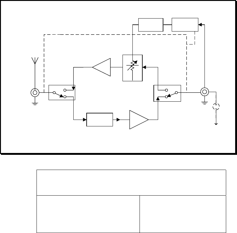
Rx Amplifier
Tx Amplifier
Bandpass
Filter
Tx Power
Reader
Tx Power
Sensor
Tx
Rx
DC
Power
Supply
Functional Block Diagram
Variable
Attenuator
In
Antenna
Tx
Rx
Page 10
10. LIMITED WARRANTY
The SmartAmp is warranted to the original purchaser to be free from defects in materials and
workmanship under normal installation, use, and service for a period of one (1) year from the
date of purchase.
Under this warranty, Teletronics International, Inc. shall repair or replace (at its option), during
the warranty period, any part that proves to be defective in material of workmanship under
normal installation, use and service, provided the product is returned to Teletronics
International, Inc., or to one of its distributors with transportation charges prepaid. Returned
products must include a copy of the purchase receipt. In the absence of a purchase receipt,
the warranty period shall be one (1) year from the date of manufacture.
This warranty shall be voided if the product is damaged as a result of defacement, misuse,
abuse, neglect, accident, destruction or alteration of the serial number, improper electrical
voltages or currents, repair, alteration or maintenance by any person or party other than a
Teletronics International, Inc. employee or authorized service facility, or any use in violation of
instructions furnished by Teletronics International, Inc.
This warranty is also rendered invalid if this product is removed from the country in which it
was purchased, if it is used in a country in which it is not registered for use, or if it is used in a
country for which it was not designed. Due to variations in communications laws, this product
may be illegal for use in some countries. Teletronics International, Inc. assumes no
responsibility for damages or penalties incurred resulting from the use of this product in a
manner or location other than that for which it is intended.
IN NO EVENT SHALL TELETRONICS INTERNATIONAL, INC. BE LIABLE FOR ANY
SPECIAL, INCIDENTAL OR CONSEQUENTIAL DAMAGES FOR BREACH OF THIS OR ANY
OTHER WARRANTY, EXPRESSED OR IMPLIED, WHATSOEVER.
Some states do not allow the exclusion or limitation of special, incidental or consequential
damages, so the above exclusion or limitation may not apply to you.
This warranty gives you specific legal rights, and you may also have other rights that vary from
state to state.