Telex C 2002 Users Manual C2002 Rev D
C-2002 to the manual 509f2f4d-722a-f304-bd41-011b436aca8e
2015-02-02
: Telex Telex-C-2002-Users-Manual-449780 telex-c-2002-users-manual-449780 telex pdf
Open the PDF directly: View PDF ![]() .
.
Page Count: 60
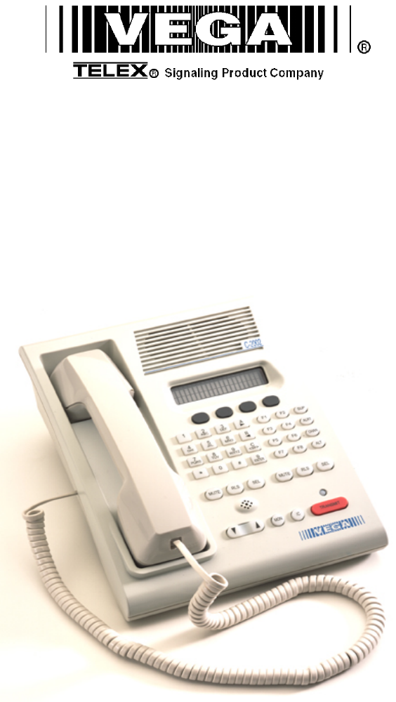
Model C-2002
Radio Control Console
Technical Manual
November 8, 2005 P.N. 803548
REV D

Remote Control Console i
Table of Contents
1 INTRODUCTION ...............................................................................................................................................1
2 CONTROLS AND INDICATORS.....................................................................................................................2
2.1 FRONT PANEL.................................................................................................................................................2
2.1.1 Common Controls and Indicators .........................................................................................................2
2.2 REAR PANEL CONNECTIONS ...........................................................................................................................3
2.2.1 Rear Panel Ports ...................................................................................................................................3
3 OPERATION.......................................................................................................................................................5
3.1 SELECTING A LINE ..........................................................................................................................................5
3.2 RELEASING A LINE ..........................................................................................................................................5
3.3 MUTING A LINE...............................................................................................................................................5
3.4 SELECTING A FREQUENCY (F-TONE)...............................................................................................................5
3.5 SUPERVISORY CONTROL .................................................................................................................................5
3.6 SENDING ALERT TONES ..................................................................................................................................5
3.7 VOLUME CONTROL.........................................................................................................................................5
4 LINE SETUP AND DESCRIPTION .................................................................................................................6
4.1 INTRODUCTION/DEFAULTS....................................................................................................................6
4.2 FEATURE DESCRIPTION ..........................................................................................................................6
4.2.1 Crossmute..............................................................................................................................................6
4.2.2 Supervisor Function ..............................................................................................................................7
4.2.3 Relay Contact Closure For Local Control ............................................................................................7
4.2.4 Two-Wire/Four-Wire Mode...................................................................................................................7
4.2.5 RX Side Settings.....................................................................................................................................7
4.2.6 TX Side Settings.....................................................................................................................................8
4.2.7 Transmit Monitor...................................................................................................................................8
4.3 LEVEL ADJUSTMENTS.....................................................................................................................................9
4.3.1 Transmit Side Adjustments ....................................................................................................................9
4.3.2 Transmit Monitor Setup.........................................................................................................................9
4.3.3 RX Level Adjustment..............................................................................................................................9
5 HARDWARE OVERVIEW .............................................................................................................................10
5.1 C-2002 CONSOLE .........................................................................................................................................10
5.1.1 Main PCB ............................................................................................................................................10
5.1.1.1 Line Interface......................................................................................................................................................... 10
5.1.2 Keypad PCB ........................................................................................................................................10
5.1.3 Display.................................................................................................................................................10
6 THEORY OF OPERATION ............................................................................................................................11
6.1 MICROPHONE INPUT PATHS..........................................................................................................................11
6.2 AUDIO OUTPUT PATHS .................................................................................................................................11
6.3 LINE RECEIVE PATHS LINE (ONE/TWO)........................................................................................................11
6.4 SYSTEM CLOCK GENERATION ......................................................................................................................12
6.5 NON-VOLATILE MEMORY (EEPROM).........................................................................................................12
6.6 USER I/O ......................................................................................................................................................12
6.7 CLONE MODE SERIAL PORT..........................................................................................................................12
6.8 POWER REGULATION AND RESET CONTROL .................................................................................................12
7 SETUP MODE...................................................................................................................................................13
7.1 TECH MODE .................................................................................................................................................13
7.1.1 Erasing all settings ..............................................................................................................................13
7.1.2 Resetting the PIN Number ...................................................................................................................13
7.1.3 Opening Display Menu........................................................................................................................14
7.1.4 Button Activated Setup Modes.............................................................................................................15
7.2 OPENING MENU ............................................................................................................................................15

ii Vega’s C-2002
7.3 LEVEL MENU SCREEN ..................................................................................................................................15
7.3.1 Menu 1 - Line Level Settings ...............................................................................................................16
7.3.1.1 RX Input Level Screen .......................................................................................................................................... 16
7.3.1.2 LAM Programming Screen.................................................................................................................................... 16
7.3.1.2.1 LAM Duration After Release screen.............................................................................................................. 16
7.3.1.2.2 LAM Trigger Level Screen ............................................................................................................................ 16
7.3.1.3 Mute Button Level Screen..................................................................................................................................... 16
7.3.1.3.1 Mute Button Level Screen.............................................................................................................................. 17
7.3.2 Main Level Settings..............................................................................................................................17
7.3.2.1 Microphones Screen .............................................................................................................................................. 17
7.3.2.1.1 Desk microphone Preamp Gain Screen .......................................................................................................... 17
7.3.2.1.2 Handset Preamp Gain Screen ......................................................................................................................... 17
7.3.2.1.3 Aux Preamp Gain Screen ............................................................................................................................... 17
7.3.2.2 Speaker Level Setting............................................................................................................................................ 17
7.3.2.2.1 Minimum Speaker Level................................................................................................................................ 17
7.3.2.3 Output Level Screens............................................................................................................................................. 18
7.3.2.3.1 TX Output Level ............................................................................................................................................ 18
7.4 SYSTEM SETTINGS SCREEN...........................................................................................................................18
7.4.1 Clock Settings Screen ..........................................................................................................................18
7.4.1.1 Clock Edit Screen .................................................................................................................................................. 18
7.4.1.1.1 Clock Hours Screen........................................................................................................................................ 18
7.4.1.1.2 Clock Minutes Screen .................................................................................................................................... 18
7.4.2 Dump Function....................................................................................................................................19
7.4.2.1 Dump Error Screen................................................................................................................................................ 19
7.4.3 Menu 2 System Setup Screen ...............................................................................................................19
7.4.3.1 Tone Settings Screen ............................................................................................................................................. 19
7.4.3.1.1 DTMF Settings............................................................................................................................................... 19
7.4.3.1.1.1 First DTMF Settings Screen ................................................................................................................... 19
7.4.3.1.1.2 Next DTMF digit Settings Screen.......................................................................................................... 20
7.4.3.1.1.3 DTMF Keypad Enable/Disable............................................................................................................... 20
7.4.3.1.1.4 Enable/Disable PTT tones with DTMF................................................................................................... 20
7.4.3.1.1.5 Select Call Timer Duration Setup ........................................................................................................... 20
7.4.3.1.2 Single Tone Settings....................................................................................................................................... 21
7.4.3.1.2.1 Guard/Function/Hold Level Settings ...................................................................................................... 21
7.4.3.1.2.2 Guard/Hold Frequencies ......................................................................................................................... 22
7.4.3.1.2.3 Guard/Hold Duration’s ........................................................................................................................... 22
7.4.3.1.3 Test Tone Screen............................................................................................................................................ 22
7.4.5.2 AUX Input Enable ................................................................................................................................................. 22
7.4.4 Menu 3 System Setup Screen ...............................................................................................................23
7.4.4.1 PIN Number Entry................................................................................................................................................. 23
7.4.4.2 TX Delay Setup ..................................................................................................................................................... 23
7.4.5 Menu 4 System Setup Screen ...............................................................................................................23
7.4.5.1 Unselect Audio Mute............................................................................................................................................. 23
7.4.5.2 Duplex Enable ....................................................................................................................................................... 24
7.4.6 Menu 5 System Setup Screen ...............................................................................................................24
7.4.6.1 MicAGC Function ................................................................................................................................................. 24
7.4.6.2 Handset installed.................................................................................................................................................... 24
7.4.7 Menu 6 System Setup Screen ...............................................................................................................24
7.4.7.1 Parallel Console UP-Date Function....................................................................................................................... 24
7.5 ALPHANUMERIC FUNCTION-LINE SETUP ......................................................................................................24
7.5.1 Line/F-Tone Selection Screen..............................................................................................................25
7.5.1.1 Line Alphanumeric Selection Screen..................................................................................................................... 25
7.5.1.1.1 Line Alphanumeric Programming Screen ...................................................................................................... 25
7.6 LINE TONE/LOCAL SCREEN ..........................................................................................................................26
7.6.1 Enable/Disable the Line ......................................................................................................................26
7.6.2 Tone or Local Control .........................................................................................................................26
7.6.3 Crossmute Setup ..................................................................................................................................26
7.6.4 Squelch Setup.......................................................................................................................................26
7.6.5 TX Monitor Enable/Disable.................................................................................................................26
7.6.6 Automatic Gain Control (AGC) Enable/Disable.................................................................................27
7.6.7 TX Enable/Disable per Line ................................................................................................................27
7.6.8 Forced Unselect of a Line....................................................................................................................27
7.6.9 DTMF ANI Decode Enable .................................................................................................................27

Remote Control Console iii
7.7 MUTE BUTTON .............................................................................................................................................27
7.7.1 Per line Mute button Setup ..................................................................................................................27
7.7.2 Incoming Select Call DTMF String Setup ...........................................................................................28
7.8 FUNCTION TONE PARAMETER SCREEN .........................................................................................................28
7.8.1 Function Tone Enabled/Disable..........................................................................................................28
7.8.2 Function Tone Setup............................................................................................................................28
7.8.3 Frequency Programming Screen.........................................................................................................28
7.8.4 Duration Display Screen .....................................................................................................................28
7.8.5 Dual Function Tone mode Screen .......................................................................................................29
7.9 SUPERVISOR ENABLE ...................................................................................................................................29
7.10 ALERT PROGRAMMING .................................................................................................................................29
7.10.1 Cadence Level Selection......................................................................................................................29
7.10.2 Cadence Frequency Selection..............................................................................................................29
7.11 MONITOR PROGRAMMING SCREEN ...............................................................................................................30
7.11.1 Monitor Characteristic Selection.........................................................................................................30
7.11.1.1 Monitor Frequency .............................................................................................................................................. 30
7.11.1.2 Monitor Duration................................................................................................................................................. 30
7.11.1.3 Monitor Level...................................................................................................................................................... 30
8 TECHNICAL DOCUMENTATION ...............................................................................................................34
8.1 C-2002 MAIN BOARD, P/N 879583 .............................................................................................................34
8.1.1 Schematic.............................................................................................................................................34
8.1.2 Bill of Material, component layout......................................................................................................34
8.2 C-2002 KEYPAD BOARD, P.N. 879573 ........................................................................................................34
8.2.1 Schematic.............................................................................................................................................34
8.2.2 Bill of Material, component layout......................................................................................................34
8.3 C-2002 TOP ASSEMBLY, P.N. 879592 .........................................................................................................34
9 WARRANTY, SERVICE, REPAIR, AND COMMENTS.............................................................................35
10 SPECIFICATIONS .......................................................................................................................................36

iv Vega’s C-2002
Table of Figures
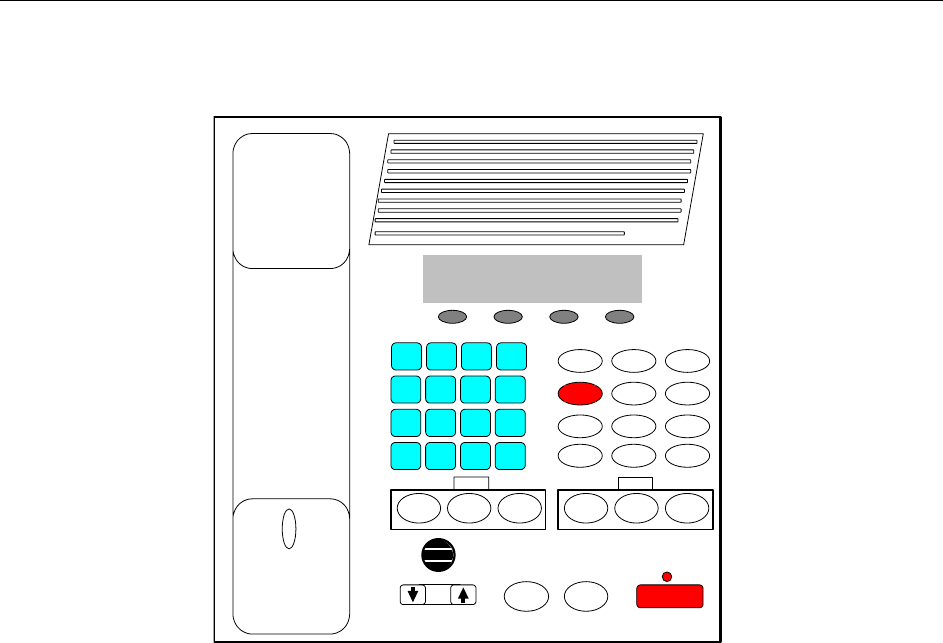
Figure 1 Front Panel Diagram .....................................................................................................................2
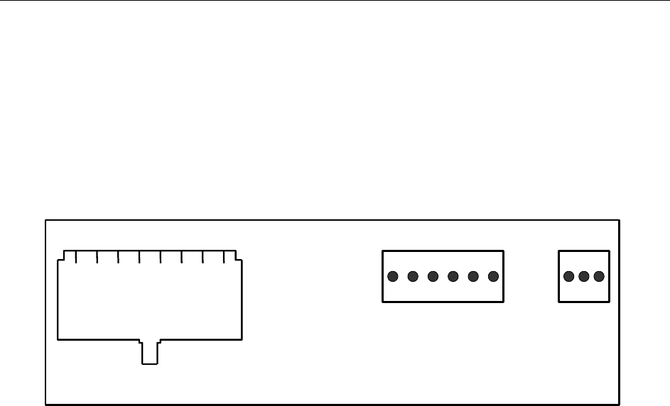
Figure 2 Rear Panel Diagram.......................................................................................................................3
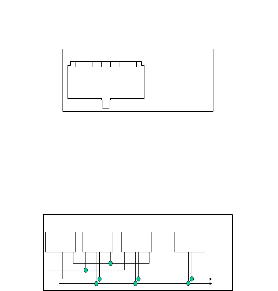
Figure 3 Rear Panel Pinout ..........................................................................................................................4
Figure 4 Line Connector Pin Out.................................................................................................................6
Figure 5 Crossmute Function example........................................................................................................6
Figure 6 Supervisor Function Example.......................................................................................................7
Figure 7 Master/Slave Console Configuration............................................................................................8
C-2002 DEFAULT SHIPPING CONFIGURATION:
The C-2002HS is shipped from the factory in the following state:
1) 4 Wire Mode
2) Full Duplex
3) TX Monitor Disabled
4) 600 Ohm TX output impedance
5) 600 Ohm RX input impedance

Remote Control Console 1
1 Introduction
The model C-2002 is a full-featured Two-Line, multi-format, and self-contained desktop radio control console. Its
sleek and modern look will compliment any surroundings.
The C-2002 is a Digital Signal Processor (DSP) based design, allowing easy field programmability using the DTMF
and soft keypads on the front of the console. Unlike other manufacturers’ equipment, no additional software is
required to program the C-2002 console. Modifications and enhancements can generally be made via a software
change only. If the user determines they require a special feature enhancement, please contact the Vega Sales
Department for cost and feasibility.
Initial Line level adjustments are made via potentiometers allowing for ease of installation. Should additional
adjustments be required, they can be made in the programming mode. AGC on receive and microphone audio paths
help stabilize line level adjustments.
The C-2002’s modular design offers control of one base station, along with selection of 99 frequencies. The line
interface offers crossmute capability and squelch control feature eliminating the unwanted noise that is generally
associated when monitoring a line.
The C-2002 will accommodate a desk microphone along with a handset (or headset) as indicated on the side of the
C-2002 console. In addition to the external microphone options, a built in panel microphone is available by pressing
the PTT on the front of the panel. When a PTT occurs from any of the three microphones, the others will mute so
as not to pick-up unnecessary ambient noise during transmission. When the handset is enabled and taken off hook
the receive audio is transferred to the earpiece.
The console is normally used in conjunction with a matching Vega 223 Series (or equivalent) tone-remote panel
located at the base station. The console is compatible with Motorola, MA/ComNet Ericsson/GE, and other tone-
remote control systems employing the industry-standard sequential tone-control format.
The console is connected to the mating panels by means of shielded voice-grade or better leased or private lines
(including microwave circuits). Metallic or DC continuity is not required.
2 Vega’s C-2002
2 Controls and Indicators
IC
1
*
7
P
Q
R
S
4
GHI
2
ABC
0
8
TUV
5
JKL
3
DEF
#
9
WXYZ
6
MNO
A
->
D
Enter
C
<sp>
B
<-
Vu Muter 11:08A
M
Ln1-Fn2 Ln2-Fn8
VOLUME
Transmit
MON
F3
F7
RLS SE
L
Mute RLS
C-2002
F8 ALT
F5 F6 Chan
F4 Alert
SUP
F2 F1
SE
L
Mute
LINE 1 LINE 2
Figure 1 Front Panel Diagram
2.1 Front Panel
Figure 1 shows a view of the Front panel. The Front panel contains the user I/O. It features a Volume control,
intercom and monitor functions, panel PTT with indicator, built in panel microphone, per line Select, Release and
Mute functions, DTMF keypad, Supervisory, Alert, Channel and ALT functions used with the F1-F8 Function Tone
selection. The C-2002 is programmed from the front panel using the four gray soft keys located below the Vacuum
Florescent LCD display provides channel/numeric indication, clock and audio-level meter.
2.1.1 Common Controls and Indicators
VU Meter: Displays Selected receive and Microphone audio bus levels. This meter is shown on the top line of the
display and utilizes the first 12 display elements from the upper left.
Program 1-4: Are used as “soft” programming buttons when in the tech mode. These buttons will have different
functions depending on the action required. The bottom line of the display will show their respective functions.
DTMF Keypad: The DTMF keypad is used for transmitting DTMF digits, selecting frequencies for tone control in
tech mode (section 6), and entering alphanumeric strings for line/function tone combinations.
Function Buttons F1-F8: When a function tone button is pressed, a guard tone and function tone burst is sent out.
No hold tone is associated with the changing of the function tone. When one of the function tones is selected it will
light to indicate which function tone is chosen, a function tone shall remain selected until the operator changes the
setting. The console will power up with the last selected line and function tone pair selected.
Supervisory button: The SUP button allows one console operator to disable any other console, which is connected
to the supervised line. The Red LED is on during supervisory and blinking when being supervised
Alert button: When pressed, a alert tone plus key–up tones will be sent to all Selected lines.
Channel button: Used to change selected line F-tone frequency via the DTMF keypad.
ALT button: Used as a Alternate or Shift function for F1-8 and Alert tones.

Remote Control Console 3
Line Buttons LN1-LN2: Three buttons are available for each Line, SELect, RLS (Release) and Mute.
SELect button: When the SEL buttons is pressed that line enters the Select mode
Select LED: The Red LED under each LNx SEL Button indicates if the line is selected for transmit audio.
RLS button: The RLS button is used to release a selected line.
RLS LED: The blinking Red LED under each LNx RLS Button indicates receive audio activity on that line.
Mute button: The Mute button is used if RX audio from that line is not to be monitored in the speaker.
Mute LED: The steady Red LED under each LNx Mute Button indicates if the line is muted from receive
audio monitoring. A blinking LED indicates a external cross-mute.
Volume Control: Adjusts the receive speaker audio and handset earpiece level of the receive inputs of the line
interfaces. A minimum volume level can be set in tech-mode, so that the console operator cannot turn the speaker
volume to zero. When adjusting the level up or down, the display shows the selected level on a relative scale.
Monitor: When the Monitor button is pressed a Monitor tone burst is sent out on the selected line. The Monitor
tone burst consists of a guard tone and function tone of 2050Hz. An LED indication lights for the duration of the
tone burst.
Intercom (IC): When the Intercom button is pressed and held down the C-2002 shall transmit audio without
activating the tone generator. Intercom is considered a PTT operation with the tone generator disabled.
Panel PTT Pushbutton: When pressed, audio from the panel microphone plus key–up tones will be sent to all
Selected lines.
Transmit LED: This LED lights when any PTT source is depressed keying up the console. It will also blink if a
2175 Hz tone is detected on the selected TX audio lines. This would indicate to the operator that another console is
currently transmitting on one of the selected channels.
2.2 Rear Panel Connections
Figure 2 shows drawing of the rear panel of the C-2002. Each of the ports shown is discussed in detail in the
following section.
2.2.1 Rear Panel Ports
Power Jack: The left most jack on the C-2002 is the Power Jack. The power supply that is included with the unit
plugs in to this location. It is a standard 2.5mm center positive plug and requires at least 12V to operate correctly.
PORT
A
UX
+12
GND
POWER
+12
DATA
PORT
LINE
1LINE
2
Figure 2 Rear Panel Diagram
4 Vega’s C-2002
Line Port: The C-2002 is equipped with two single line jacks. The connector is a standard eight pin RJ-45. The
pinout of the connector appears in Figure 3. The numbering of the pins is shown in Figure 3 for reference. In
addition to the standard RX and TX pin pairs, the unit also can be supervised and supports cross mute functions.
Pins 7 and 8 of the Line connector can be used as a form C closure relay for local control. Pins 7 and 8 form the
closure during any PTT operation. An internal resistor makes an external connection to ground un-necessary, and
can be removed to remove ground from the closure path.
Auxiliary Audio Input: The external 6 pin terminal block provides an Audio Input (1), PTT (2), and GND (6)
line. Pulling PTT to ground activates the Audio Input line for transmitting audio from an external source. This
input is a high impedance capacitance coupled input.
Auxiliary Speaker: Pin 1 of the AUX Port is a capacitance coupled low impedance output that can be used to
drive an external speaker amplifier. Output level is controlled by the front panel volume control.
1 2 3 4 5 6 7 8 1) Cross Mute I/O
2) Supervisor I/O
3) RX +
4) TX +/(RX+2W)
5) TX -/(RX - 2W)
6) RX -
7) Local
8) GND/Local
Rear Panel Connector Pinouts
1 2 3 4 5 6
1) RX Audio 2) PTT
3) +12V 4) Aux Audio In
5) Earth GND 6) Sig GND
1 2 3
1) TXD
2) RXD
3) GND
Figure 3 Rear Panel Pinout
Battery backup: The +12V power input on the AUX Port is used for battery backup and is a diode-protected
input.
Earth Ground: The Earth ground connection on the AUX Port MUST be connected for proper operation. It
provides a path for any external noise to be shunted to.
Data port: This port is a 0 to 10V asynchronous port used for cloning one C-2002 to another. The cable is not
supplied but the connector is. To connect two units, RX on one console should be connected to TX of the other
console. Ground is connected straight through. This is a non-standard serial port used only for the C-2002 cloning
function.

Remote Control Console 5
3 Operation
3.1 Selecting a line
Selection of a line for transmit occurs when the “SEL” button is pressed and the LED under the switch lights, to
transmit on both lines press the “ALT” button then the “SEL” button of the opposite line.
3.2 Releasing a line
To release a selected line from transmit press the “RLS” button for the selected line. If the “RLS” button LED is
blinking RX audio was present on the line during the last 10 seconds or the time preset in tech-mode.
3.3 Muting a line
To mute a particular lines RX audio from the speaker press the “Mute” button. The mute button can be configured
for both latched or timed operation. If the “Mute” button LED is blinking a parallel console is transmitting on that
line and the console is being muted to reduce feedback squeal.
3.4 Selecting a frequency (F-Tone)
Selection of a F-tone can be accomplished in different ways, with a line selected simply press the desired F-tone
(F1-F8) and the associated Line and F-tone alphanumeric will be displayed on the second line of the display, if F9-
F16 are desired press the “ALT” button then the F-tone required (ALT + F3=F11).
The “Chan” button along with the DTMF keypad can also be used to change a F-tone, with a line selected simply
press “Chan” + “05” to set F5 for the selected line, “Chan” + “12” to set F12.
When both lines are selected any of the above methods will change the F-tone for both lines, to change only one of
the lines F-tone when in a group mode, simply hold down the desired lines “SEL” button and perform any of the
above methods.
3.5 Supervisory control
If supervisory control of a line is required, simply press the “SUP” button and all parallel consoles will be locked
out from use of this line, parallel consoles will display a blinking LED under the “SUP” button if they select a
supervised line. When completed simply press the “SUP” button again to release control of the line, now all
consoles will have use of the line for transmit.
3.6 Sending Alert tones
With a line selected, simply press the “Alert” button to generate an alert tone. If programmed in tech-mode the
“ALT” + “Alert” can be used to generate a different alert tone.
3.7 Volume Control
Holding down the selected line button and scrolling the volume meter on the display with the UP/DOWN volume
control button can adjust speaker volume.
Earpiece audio can be adjusted using the UP/DOWN volume control with the handset off-hook.
6 Vega’s C-2002
4 Line Setup and Description
4.1 INTRODUCTION/DEFAULTS
1 2 3 4 5 6 7 8 1) Cross Mute I/O
2) Supervisor I/O
3) RX +
4) TX +/ (RX + 2W)
5) TX -/ (RX - 2W)
6) RX -
7) Local
8) GND/Local
Connector View
Figure 4 Line Connector Pin Out
The Line interface for the C-2002 console provides communication with any standard tone remote system.
Figure 4 shows the pin out of the line interface connector, which is on the rear panel (See Figure 2 and
Figure 3).
4.2 FEATURE DESCRIPTION
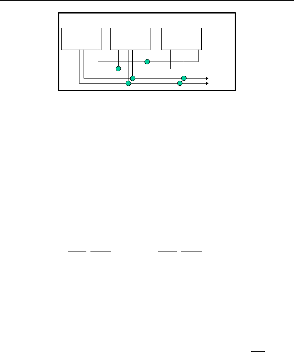
4.2.1 Crossmute
When a parallel console operator keys a microphone in the same room, the crossmute function mutes the receive
audio path of the other parallel consoles. This prevents any unwanted audio loops that could occur, causing a loud
squeal on the paralleled speakers.
1 2 3 4 5 6 7 8 1 2 3 4 5 6 7 8 1 2 3 4 5 6 7 8 1 2 3 4 5 6 7 8
Console 1: Console 2: Console 3:
Offsite
Console 4:
Line +
Line -
Line 1 Line 1Line 1Line 1
Figure 5 Crossmute Function example.
Feedback may be avoided by muting the receive audio of the other consoles which are in parallel with a transmitting
console. This may be accomplished by connecting pins 1 and 8 of each of the consoles to be crossmuted as shown
in Figure 5. Pin 8 must be connected to provide a common ground. Figure 5 illustrates the connections between
consoles 1 through 3 that are in the same room and when one transmits, the receive audio on the other consoles will
be muted. Console 4 is off-site with no possibility of feedback, therefore, it is not connected and will not be muted.
Note: The intercom function will not work between crossmuted consoles.
Remote Control Console 7
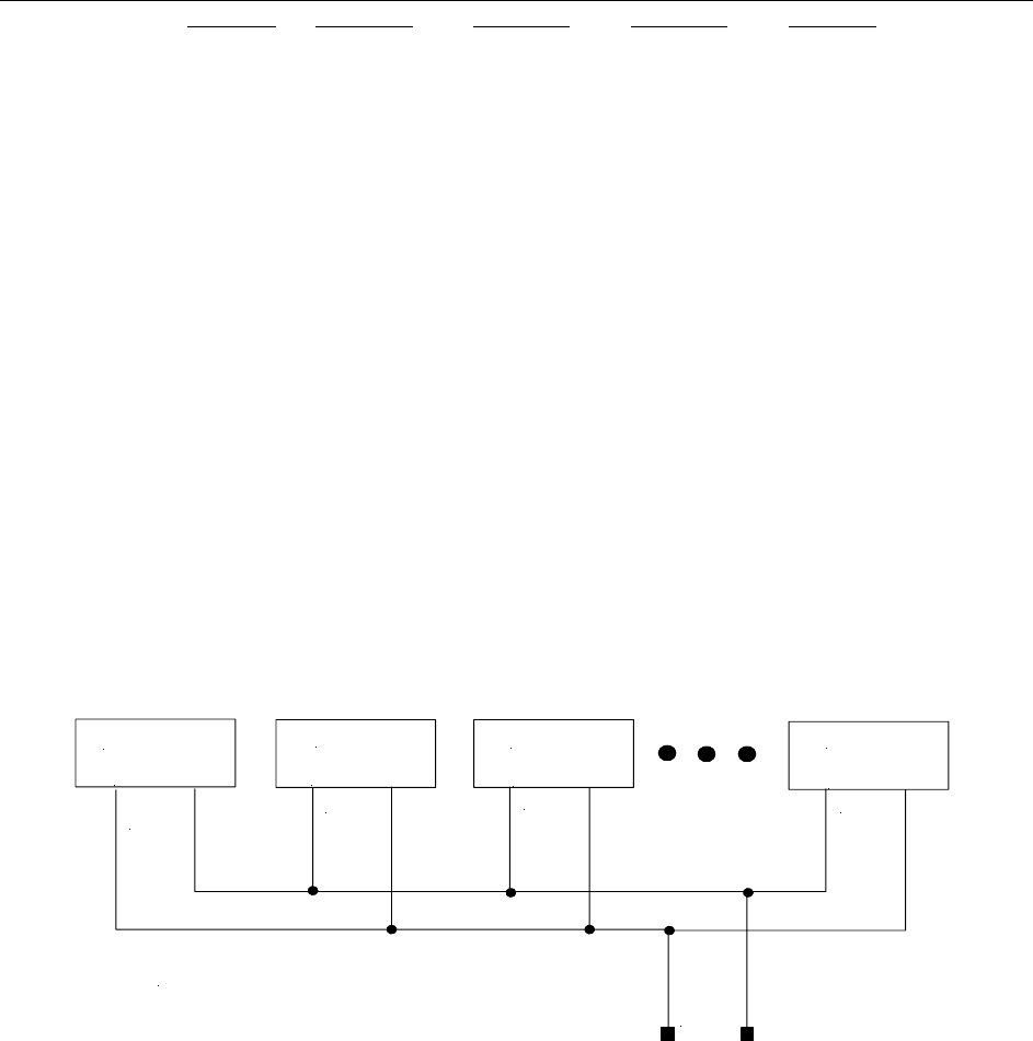
4.2.2 Supervisor Function
1 2 3 4 5 6 7 8 1 2 3 4 5 6 7 8 1 2 3 4 5 6 7 8
Console 1: Console 2: Console 3:
Line +
Line -
Line 1 Line 1Line 1
Figure 6 Supervisor Function Example.
The Supervisor Function enables a console, such as the C-2002, which has the capability to drive this line, to
disable all units on a particular line. This includes both PTT and RX audio. Its connection is similar to that of the
crossmute function. By wiring alone, it is possible to setup only specific consoles with this feature. Figure 6 shows
the connection scheme required to utilize this function. Pin 2 of all consoles are connected together. In addition,
Pin 8 is also connected together on all consoles, serving as a common ground for all consoles. Assuming that
console 1 has supervisory capability, when activated, Line 1 on parallel consoles 2 and 3 would then be inhibited
from both Transmit and Receive.
4.2.3 Relay Contact Closure For Local Control
The relay is normally open and provides a dry contact closure during PTT functions between pins 7 and 8 of the line
jack. The relay closure can carry 500mA at 12VDC or 250mA at 115VAC. When using the intercom function the
relay is not activated. If this relay closure is used for local control (or any other case where tone bursts are not used
for signaling) disabling the tone generation is recommended by entering the setup mode.
4.2.4 Two-Wire/Four-Wire Mode
The C-2002 comes standard with a jumper selectable two or four-wire option. Note: The C-2002 is shipped in the
four-wire mode. Two-wire mode is accomplished by the following jumper positions:
Two-Wire: Jumper Position Jumper Position
Line 1 JP18 A Line 2 JP22 A
Line 1 JP19 A Line 2 JP23 A
Four-Wire: Jumper Position Jumper Position
Line 1 JP18 B Line 2 JP22 B
Line 1 JP19 B Line 2 JP23 B
The RX pair is now on pins 3 and 6 on the connector and the TX pair is on pins 4 and 5. Once the transmit and
receive paths are separated the impedance of each side must be set.
4.2.5 RX Side Settings
In 4 Wire mode, the RX side is jumper selectable for a 600 ohm impedance or 10k ohm impedance. If only one
console is on the line (no parallel consoles) then place J17 (Line 1) or J25 (Line 2) in the A position for a 600 Ohm
line impedance. If more than one console is on one line, then place J17 (Line 1) or J25 (Line 2) on ONE console in
the A position and all other consoles in the B position. Each console added to the system will result in line loss.
The following chart gives an indication as to how much loss can be expected. The first console in the system is set
for an impedance of 600 ohms out (approximately). Each console added to the system thereafter is set for an
impedance of 10k ohms. As the chart indicates on the following page , the more consoles bridged on the line, the
lower the line impedance and the greater the loss in audio level. In 2 Wire mode, all consoles should have J17
(Line 1) or J25 (Line 2) in the “B” position.
8 Vega’s C-2002
Console # J8 Position Impedance Impedance Loss (dB)
1 A 604 604 0.0
2 B 10k 569 -0.5
3 B 10k 539 -1.0
4 B 10k 511 -1.5
5 B 10k 486 -1.9
6 B 10k 464 -2.3
Level adjustment can be made to the receive audio by entering the setup mode or adjusting the RX level POT inside
the C-2002.
4.2.6 TX Side Settings
The C-2002 TX output circuitry has a DPDT relay that is used to connect and disconnect the TX output transformer
from the TX line based on PTT status. This allows a very large number of consoles to be attached to the line in
parallel, because only the transmitting unit will be directly connected to the line. When not transmitting, the DPDT
relay is connected to 600 ohms or open circuit depending on the number of console connected in parallel to the line.
If only one console is attached, this unit should have J16 (Line 1) or J26 (Line 2) in the “A” position. This makes it
the effective master and terminates the line with 600 ohms. If there are more than one console connected in parallel,
one console should be designated as the master by placing J16 (Line 1) or J26 (Line 2) in the “A” position and the
remaining consoles should be designated as a slave and should have J16 (Line 1) or J26 (Line 2) placed in the “B”
position. In this manner, the impedance looking back into the parallel configuration of consoles is still 600 ohms.
Figure 7 shows the basic configuration. The C-2002 could also be the master in this configuration. NOTE: If any of
the consoles connected in parallel are not C-2002’s, then all the C-2002’s should be configured as slaves.
Additionally, J2 (Line 1) or J4 (Line 2) should be used as a TX line impedance correction if there are consoles other
than the C-2002 connected in parallel. J2 (Line 1) or J4 (Line 2) position “B” adds another 600ohms to the output
TX line. J2 (Line 1) or J4 (Line 2) Position “A” is straight through.
Master
Slave
Slave
Slave
J12 POS A
J12 POS B
J12 POS B
J12 POS B
C2000 Multiple Console Configuration
Leased
Line
600
ohms
open
open
open
Figure 7 Master/Slave Console Configuration.
4.2.7 Transmit Monitor
In a four-wire system with parallel consoles, the transmit line may be monitored. Refer to section 4.3.2, the monitor
level setup on adjusting the level. The transmit monitor is not needed in two-wire mode as the transmit audio is
already on the receive circuit. The transmit monitor, in 4 wire mode, is used to detect transmit activity for the TX
Detect LED.

Remote Control Console 9
4.3 Level Adjustments
4.3.1 Transmit Side Adjustments
The transmit audio consists of multiple audio sources – microphone audio, AUX input, function tones, and DTMF
tones. Each audio sources is summed or generated in the DSP with the analog signal being generated on a single
DAC. The following is a list of the potentiometers that affect the transmit path.
Reference Description
R125 Line 1 TX Output Level Adjustment
R123 Line 1 TX Monitor Level Adjustment
R143 Line 2 TX Output Level Adjustment
R162 Line 2 TX Monitor Level Adjustment
R196 Desk Microphone Adjustment
MIC INPUT LEVEL ADJUST:
Care should be taken to avoid overdriving the input TX circuitry, as this will distort the audio. Make sure you have
enabled the desired Microphone connection in setup mode. Saying and holding the word “Four” is a good audio
level test vocalization. Use a strong tone of voice.
When adjusting the Desk Microphone audio input level, make sure that the Desk Microphone is at the normal
distance from the operator when setting the level. Connect a oscilloscope to Test point TP13 and adjust R196 to
approximately 3.5Vp-p.
TX OUTPUT LEVEL ADJUST:
The transmit level potentiometer is used to adjust the output level of the transmit audio so that it is calibrated with
the tone levels that were set in setup mode. Calibration of the TX line will vary depending on system variables as
well as the number of consoles found in parallel on the line. A easy way to align the console for the correct level is
to press and hold the PTT key. While the console is keyed up, the unit will, by default, generate a Hold tone at
–20dBm. A meter reading dbm can then be used and R125 (Line 1) or R143 (Line 2) adjusted to read the correct
value.
4.3.2 Transmit Monitor Setup
The transmit monitor provides a portion of the transmit audio of a four-wire circuit to the receive path. This allows
the console operator to listen to the transmissions of parallel console operators. To set this level have a parallel
console operator press the intercom button. Adjust R123 (Line 1) or R162 (Line 2) until the level is comfortable in
the handset/headset earpiece or the speaker. Make sure this feature is enabled or no audio will be passed.
See Setup Mode.
4.3.3 RX Level Adjustment
The RX level should be adjusted so that the maximum level coming into the console use the entire range of the
ADC, which is 0-4V. A test tone of +3dBm to -5dBm coming into the line interface is a good value to use. Adjust
R153 (Line 1) so that the signal seen on an oscilloscope at Test point TP11 is approximately 3.5Vp-p or R161
(Line2) so that the signal seen on an oscilloscope at Test point TP12 is approximately 3.5Vp-p

10 Vega’s C-2002
5 Hardware Overview
The C-2002 is a Two-line, multi-mode console designed specifically for small to medium level system
requirements. All functions are housed in a single small modern looking console.
5.1 C-2002 Console
The C-2002 consists of the following sub-assemblies enclosed in the single case: Main Processing Board, Keypad
PCB and Display.
5.1.1 Main PCB
The Main PCB is mounted to the bottom of the enclosure using 4 #6 screws. It contains the DSP that handles all
audio processing and user interface features. Two stereo Digital to Analog Converter (DAC) is utilized to generate
audio for transmission, handset sidetone, and receive audio. Two stereo Analog to Digital Converter (ADC) on the
main board digitizes audio from the line, microphones and the auxiliary interface. All audio detection, generation,
and filtering are performed within the DSP. Seven potentiometers are available for I/O signal level adjustment, in
addition to the software level control.
5.1.1.1 Line Interface
The Line Interface is an 8 pin RJ-45 connector, using either the standard tone control format compatible with
Motorola and M/A ComNet Ericsson/GE or Local Control relay closure. The line interface may be hardware
configured for either two-wire or four-wire operation and may be factory modified to accommodate non-industry
standard tone control formats if desired. This is usually a software only change.
5.1.2 Keypad PCB
The Keypad board is interfaced to the main board via a 40-pin ribbon cable. The Keypad board contains the LED’s,
the entire key map matrix and the panel microphone. The driver circuitry for each component is located on the Main
PCB.
5.1.3 Display
A Vacuum Florescent LCD display provides channel/numeric indication, clock and audio-level meter. The display
is mounted to the front panel and is connected via a 14-pin IDC cable assembly.

Remote Control Console 11
6 Theory of Operation
The C-2002 is a Digital Signal Processor (DSP) based product. Because of this, many of the signals that once could
be probed on older products, are handled within the DSP itself. This would include DTMF generators and
decoders, notch filters, tone generators and decoders, and all of the audio summing. A great deal of the gain
controls are included within the software of the DSP. There are four analog audio sections on the C-2002, they are:
RX Input: Audio received on the line from an external source.
RX Output: RX Input audio that has been sampled and processed by the DSP, then sent to a local speaker.
TX Input: Audio from a local microphone, handset or auxiliary audio source.
TX Output: TX Input audio that has been sampled and processed by the DSP, or internally generated
Tones/DTMF that is summed with TX Input audio. The result is routed to TX line out.
The following sections discuss the portions of the C-2002 that can be tested using a common oscilloscope and
voltage meter by a qualified service technician.
6.1 Microphone Input Paths
Audio can be input from four locations. These are the desk microphone jack (J24, RJ-11 modular), handset jack
(J21, RJ-12 modular), panel mic (built into keypad PCB), and the auxiliary connector (J36) on the rear of the unit.
For each of these inputs, a single inverting Op-Amp gain stage exists to bring the maximum expected level of the
audio up to approximately 3.8Vp-p. This is the optimum level for the analog to digital converters (ADC). The trim
potentiometer R196 set the audio levels from the desk microphone jack, there is no Handset microphone gain
adjustment. All audio inputs, mentioned previously, share one half of the ADC (U12) with a CMOS switch (U34-B)
used to route audio from the appropriate source to the actual input pin of the ADC. The auxiliary input (J36-4) is
used to include an additional audio source into the transmit path. It has an integrated PTT (J36-2) input that when
pulled low will select audio from this source for transmission. Audio or tone levels injected at the Auxiliary input
should be on the order of 1.5 Vp-p, as the fixed gain ratio of R190/R189 = 2 and the target ADC level is
approximately 3.5vp-p. There are no hardware adjustments available for the Panel microphone.
6.2 Audio Output Paths
SPEAKER AUDIO:
Speaker audio originates, as all audio output signals do, from the DSP. The digitized audio is clocked to DAC U10,
pin 1. The analog audio is sourced on U10 pin 8, passes through an analog filter and inverting gain stage U14-A,
before arriving at the speaker audio driver U24. The two Watt speaker driver audio is passed to the speaker
connector J5. Speaker audio levels are software controlled.
TRANSMIT AUDIO LINE (ONE/TWO):
Transmit audio, still digitized, is clocked to U9 pin 1 for both transmit channels. Analog transmit audio can be seen
on U9 pins (8/5). Transmit audio passes through an analog filter before reaching the output gain stage. TX output
levels can be adjusted for lines (1/2) by potentiometers (R125/R143). Each Transit audio path is 600 Ohm
transformer coupled (T1/T4) and engaged during PTT by a relay contact closure (K4/K6). Transmit audio can be
found on connectors (J11/J27) pins 4(TX+) and 5(TX-).
HANDSET SIDETONE:
Handset sidetone is taken from U10 pin 5 and filtered. The output goes to an inverting op-amp stage and is coupled
through a 0.1uF cap and 150 ohm resistor. The sidetone level can be measured at TP10.
For complete schematic details, refer to Section 10 the Specifications section.
6.3 Line Receive Paths Line (One/Two)
Receive audio input can be found on the Line input connectors (J11/J27) pins 3(RX+) and 6(RX-). The receive
audio will pass through lightning protection and filtering before reaching a 10K transformer (T2/T3). The receive
audio path can be loaded to 600 Ohms by placing jumper (J17/J25) in the “A” position. Following the transformer
stage is a gain stage. Potentiometers (R153/R161) can be used to set receive audio levels at the ADC. This level can
be measured at test points (TP11/TP12). Finally, receive audio is sampled at U13 (pin 8/pin5).

12 Vega’s C-2002
6.4 System Clock Generation
The system clock is derived from a single 32.7680MHz Crystal Oscillator (Y1). The ADSP2189 DSP (U1)
processor uses this clock to generate a 65.536MHz internal instruction clock rate. The system clock is routed to the
Altera EPM7032AE44 PLD (U5) and divided into the signals necessary for audio processing. These signals include
the MCLK (2.048MHz), SCLK (512kHz), LRCLK (8kHz) and FS (16kHz frame sync). Another signal generate by
the PLD is B0 (U5-28). This signal is used by DSP software to sync the bit frames at start up. B0 is the inverse of
LRCLK. U5-31 is a clock signal that is the inverse of SCLK. The DSP serial port requires this signal, usually called
the bit clock.
6.5 Non-Volatile Memory (EEPROM)
All the system configuration and parameter storage is maintained in the non-volatile memory of U3. The serial
EEPROM AT24C16, has 16kbits of memory. The DSP writes and reads to the EEPROM via two of its Flag Pins.
6.6 User I/O
The Keypad and Seven Segment display are the main components to the User I/O scheme. The DSP controls the I/O
with a series of register and latches (U22, U23, U26, U27, U28, U16). Chip Selects originate from the DSP, but are
modified to their usable state by the PLD. The Chip selects are R-CS0,1(read) and W-CS0,1,2,3(write). They are
generated by DSP signals RD, WR, IOMS and address lines A0,A1,A5.
6.7 Clone Mode Serial Port
The C-2002 can be used to copy the memory contents of one C-2002 to another. This is done with the serial data
port on the back of the unit (J3). The circuitry used is a simple level conversion scheme to take the 3.3Vdc serial
data stream from the DSP and convert it to a 10Vdc signal at the port. The port can only be used C-2002-to-C-2002.
A standard 16C550 UART U18 is included in the DSP’s memory map. The UART levels are converted to standard
RS-232C by U20. The C-2002 firmware code can be updated through this port from any Windows 9x or greater
PC. See the www.vega-signaling.com website for software updates.
6.8 Power Regulation and Reset Control
Input power is a 12Vdc wall mount regulator. The input connector (J35) is a center positive, 2.5mm jack. It is
connected to protection circuitry consisting of a fuse and dual diodes used to protect the source if auxiliary power is
connected to J36. The system DC power requirements are 3.3V and 2.5V(U8) for the DSP and 5V(U6), 10V(U7)
for the analog circuitry.

Remote Control Console 13
7 Setup Mode
7.1 Tech Mode
The tech mode allows a technician to program the internal settings of the C-2002 console. The tech mode is entered
by pressing MUTE-F6-* simultaneously. The technician will be required to enter a PIN number to allow entry.
See the section 7.4.4.1 on setting up the PIN number. The Opening Menu is displayed when tech mode is entered.
In addition to the information on the display you will visual see the MON, SEL 1-2, MUTE 1-2, F1-F8, SUP and
the ALERT buttons also flash indicating you are in the tech mode of operation. These buttons also provide setup
options when pressed, refer to sections 7.6 and up for additional information.
7.1.1 Erasing all settings
All of the settings in the console can be reset to factory defaults by
pressing and holding both “IC” and “*” and then applying power.
The screen displayed asks if the user wants to restore defaults or not.
PROG1 - Answer, YES and you will clear all settings to the factory defaults.
PROG3 - Answer, NO and you will enter the user mode.
7.1.2 Resetting the PIN Number
In the event the PIN number is either forgotten or not known, the test jumper J15 on the main board inside the unit
can be used to enter a self test mode and reset the PIN. With the power removed from the unit, move J15 to the “B”
position on the board. Power up the board. The PIN number is cleared allowing immediate entry into the tech
mode. Power down the board and move the J15 back to the “A” position. Close the case and resume normal
operations with the C-2002.
Restore Defaults?
YES NO
PROG1 PROG2 PROG3 PROG4

14 Vega’s C-2002
7.1.3 Opening Display Menu
|----------Level menu Screen
| |---------- Line Level Settings (Select LEDS Blink)
| | |---------- RX Input Level
| | |---------- LAM Programming
| | | |---------- LAM duration after release
| | | |----------Trigger Level
| | | |----------Select/Unselect Settings
| |---------- Mute Level Settings (Mute LEDS Blink)
| | | |----------ON/OFF/Level
| |----------Main Level Settings
| | |----------Microphones
| | | |---------- Desk microphone preamp gain
| | | |----------Handset preamp gain
| | | |----------Aux input preamp gain
| | |----------Speaker Levels
| | | |----------Minimum SPKR Level
| | |----------TX Menu
| | | |----------TX Audio Output Level
|----------System Settings Screen
| |----------Menu 1
| | |----------Clock
| | |----------Dump (RS-232C clone command)
| | | |----------Dump Error Screen
| |----------Menu 2
| | |----------Tone Settings
| | | |---------- DTMF Settings
| | | | |---------- DTMF Output Level
| | | | |----------Tone duration
| | | | |----------Tone Spacing
| | | | |----------Hang Time
| | | | |----------Keypad Enable/Disable
| | | | |----------PTT with DTMF Enable/Disable
| | | | |----------DTMF RX Hold
| | | |----------Single Tone Settings
| | | | |----------Guard/Function/Hold Levels
| | | | |----------Guard/Hold Frequencies
| | | | |----------Guard/Hold duration’s
| | |----------AUX IN
| |----------Menu 3
| | |----------Tech mode PIN Number
| | |----------TX Delay setup
| |----------Menu 4
| | |----------Unselect
| | |----------Duplex
| |----------Menu 5
| | |----------MicAGC Enable/Disable
| | |----------Handset Connected
| |----------Menu 6
| | |----------Parallel Console UP-Date
|----------Alphanumeric Decision Screen
|----------Line/FTone Selection screen (Blinking Line Select LED)
| |----------Line Alphanumeric Selection screen
| | |---------- Line Alphanumeric Programming Screen
Remote Control Console 15
7.1.4 Button Activated Setup Modes
|----------LN1-LN2 - Per Line Parameters Setup
| |----------Line Enable/Disable
| |----------Tone/Local Setting
| |----------Crossmute Enable/Disable
| |----------Squelch
| |----------TX Monitor Enable/Disable
| |----------AGC
| |----------TX Enable/Disable
| |----------Unselect Normal/Locked
| |----------DTMF ANI Decode Enable
|----------F1-F16 - Function Tone Parameter Screen
| |----------Function Tone Enable/Disable
| |----------Tone Programming Screen|
| |-----------Frequency Programming Screen
| | |-----------Duration Programming Screen
|----------SUP - Supervisor Function Enable/Disable
|----------MUTE - Mute Button Setup
| |----------Timed/Momentary
| |----------Timed Mute Duration Setup
| | |----------Incoming Select Call Setup
| | |----------Select Call Timer Setup
| |----------DTMF Rx Setup
|----------MON - Monitor Programming Screen
|----------Auto/Manual Selection
|----------Monitor Tone Selection
|----------Monitor Frequency
|----------Monitor Duration
|----------Monitor Level
7.2 Opening menu
The following buttons are active during this screen:
PROG1 - Pressing this button enters the Level Menu Screen.
PROG2 - Directs the display to the System Settings Screen.
PROG3 - Directs the display to the Alpha Settings Screen.
PROG4 - Exits the Setup Mode.
LN1-LN2 - Directs the display to the Line Tone/Local Screen.
F1-F8 - Function Tone Parameter Screen.
SUP - Enables supervisor mode.
MUTE - Set mute functionality.
ALERT - Directs the display to the Alert Cadence Programming Screen.
MON - Directs the display to the Monitor Programming Screen.
7.3 Level Menu Screen
When this screen is displayed the following buttons are active:
PROG1 - Direct display to Main Level Settings Screen.
PROG4 - Go back to Opening Menu.
Pressing any Line button - Displays the Line Level Setting Screen for that selected line.
Pressing any Mute button – Displays the PER line level of mute for that selected line.
PROGRAMMING MODE
LVLS SYS ALPHA EXIT
PROG1 PROG2 PROG3 PROG4
Select Line/Main
M
ain back
PROG1 PROG2 PROG3 PROG4
16 Vega’s C-2002
7.3.1 Menu 1 - Line Level Settings
This screen is displayed after a line has been selected from the Level Menu Screen. The selected line number is
shown on the display and the select LED for that line continues to blink. In this example Line 1 has been selected.
PROG1 - Go to RX Input Level Screen.
PROG2 - Go to LAM level setup.
PROG3 - Go to Line Levels Screen.
PROG4 - Return to Level Menu Screen.
7.3.1.1 RX Input Level Screen
The RX input levels serve as a master level adjustment allowing small adjustments in gain. This is a per line
adjustment. Typically these are left at 0 dB.
PROG1 - Resets level setting to default of -60dB.
PROG2 - Increments the level setting by 1 dBm (max of 0dB).
PROG3 - Decrements the level setting by 1 dBm (min of -60dB).
PROG4 - Return to Other Line Level Screen.
7.3.1.2 LAM Programming Screen
This screen shows the current settings for the Line Activity Monitor for the line number shown. The -U or -S after
the channel number denotes whether the settings are for Select or Unselect Audio. Pressing PROG1 or PROG2 will
modify the settings for the Select or Unselect characteristics displayed when the button is pressed.
PROG1 - go to LAM Duration After Release screen.
PROG2 - go to LAM Trigger Level Screen.
PROG3 - Toggle Select or Unselect LAM control.
PROG4 - Return to Other Line Level Screen.
7.3.1.2.1 LAM Duration After Release screen
This parameter determines how long the LAM light will flash after the triggering signal disappears.
PROG1 - Resets duration setting to default of 7 seconds.
PROG2 - Increments the time setting by 1 second (maximum of 25sec).
PROG3 - Decrements the time setting by 1 second (minimum of 0sec).
PROG4 - Saves the current duration setting and returns to the LAM
Programming Screen.
7.3.1.2.2 LAM Trigger Level Screen
These parameters determine the audio level required to trigger the LAM function.
PROG1 - Adjusts level at which the LAM triggers.
PROG2 - Increments the level setting by 1 dBm (max of 0dBm).
PROG3 - Decrements the level setting by 1 dBm (min of -30dBm).
PROG4 - Saves the current level setting and returns to the LAM
Programming Screen.
7.3.1.3 Mute Button Level Screen
These parameters are used to set the level of Mute on a Per line bases.
PROG1 – Sets level of mute to off (total quite).
PROG3 – Go to Edit level screen.
PROG4 - Return to Level Menu Screen.
Line 1 level adjust
RX LAM back
PROG1 PROG2 PROG3 PROG4
Ln1 Min Rx lvl -60dB
-60dB dwn u
p
back
PROG1 PROG2 PROG3 PROG4
LAM1-S 7sec -10dBm
dur lvl S/U back
PROG1 PROG2 PROG3 PROG4
LAM1-S Duration 7se
7sec dwn u
p
back
PROG1 PROG2 PROG3 PROG4
LAM1-U Level -10dB
-10dB dwn u
p
back
PROG1 PROG2 PROG3 PROG4
M
ute1 Level = -10dB
OFF edit back
PROG1 PROG2 PROG3 PROG4
Remote Control Console 17
7.3.1.3.1 Mute Button Level Screen
These parameters determine the level of Mute on a Per line bases.
PROG1 – Resets level setting to default of –10db.
PROG2 - Increments the level setting by 1db (maximum of –10db).
PROG3 - Decrements the level setting by 1db (minimum of -30sec).
PROG4 - Saves the current level setting and returns to the Mute Programming Screen.
7.3.2 Main Level Settings
PROG1 - Go to Microphones Screen.
PROG2 - Go to Speaker Level Screen.
PROG3 - Go to the Transmit Level Screen.
PROG4 - Return to Opening Menu.
7.3.2.1 Microphones Screen
PROG1 - Go to Desk microphone Preamp Gain Screen.
PROG2 - Go to Handset Preamp Gain Screen.
PROG3 - Go to the aux input levels screen.
PROG4 - Return to Main Level Settings screen.
7.3.2.1.1 Desk microphone Preamp Gain Screen
The current setting is shown in the upper right hand corner of the
screen. This setting is for the pre-amp level of the deskmic.
PROG1 - Resets level setting to default of +0dB.
PROG2 - Increments the level setting by 1 dB (maximum of +10dB).
PROG3 - Decrements the level setting by 1 dB (minimum of -10dB).
PROG4 - Saves the current level setting and returns to the Microphones screen.
7.3.2.1.2 Handset Preamp Gain Screen
PROG1 - Resets level setting to default of +0dB.
PROG2 - Increments the level setting by 1 dB (max of +10dB).
PROG3 - Decrements the level setting by 1 dB (min of -10dB).
PROG4 - Saves the current level setting and returns to the
Microphones screen.
7.3.2.1.3 Aux Preamp Gain Screen
PROG1 - Resets level setting to default of +0dB.
PROG2 - Increments the level setting by 1 dB (max of +10dB).
PROG3 - Decrements the level setting by 1 dB (min of -10dB).
PROG4 - Saves the current level setting and returns to the
Microphones screen .
7.3.2.2 Speaker Level Setting
This setting is used to set the minimum volume level that an operator will be allowed to turn the speaker to.
PROG1 - Go to Microphones Screen.
PROG2 - Go to Speaker Level Screen.
PROG3 - Go to the Transmit Level Screen.
PROG4 - Return to Opening Menu .
7.3.2.2.1 Minimum Speaker Level
PROG1 - Resets level setting to default of -60dB.
PROG2 - Increments the level setting by 1 dB (maximum of 0dB).
M
ute Level = -10dB
-10db dwn u
p
back
PROG1 PROG2 PROG3 PROG4
M
ain level adjust
M
IC SPKR TX back
PROG1 PROG2 PROG3 PROG4
M
ain Mic adjust
desk hand aux back
PROG1 PROG2 PROG3 PROG4
Deskmic level 0dB
0dB dwn u
p
back
PROG1 PROG2 PROG3 PROG4
Handset level 0dB
0dB dwn u
p
back
PROG1 PROG2 PROG3 PROG4
A
ux-in level: 0dB
0dB dwn u
p
back
PROG1 PROG2 PROG3 PROG4
M
ain level adjust
M
IC SPKR TX back
PROG1 PROG2 PROG3 PROG4
M
in Spkr level -60dB
-60dB dwn u
p
back
PROG1 PROG2 PROG3 PROG4
18 Vega’s C-2002
PROG3 - Decrements the level setting by 1 dB (minimum of -60dB).
PROG4 - Saves the current level setting and returns to the SPKR menu.
7.3.2.3 Output Level Screens
Entering the TX output level screen allows for setting output levels.
7.3.2.3.1 TX Output Level
The TX output level is adjusted as shown on the display. This is an overall output gain control for the line. It can
be used to make small adjustments to the line level performance. The typical value is 0 dB.
PROG1 - Resets level setting to default of 0dBm.
PROG2 - Increments the level setting by 1 dBm (max of +10dBm).
PROG3 - Decrements the level setting by 1 dBm (min of -10dBm).
PROG4 - Saves the current level setting and returns to the Line Level
Setting screen.
7.4 System Settings Screen
This menu is entered by selecting PROG2 from the PROGRAMMING MODE menu. Once in this mode there are 5
different menus that can be entered. Each is brought up sequentially by pressing the PROG3 button labeled next on
the display.
PROG1 - Clock Set Routines.
PROG2 - Dump setup memory to another console.
PROG3 - Next Menu.
PROG4 - Return to Opening Menu.
7.4.1 Clock Settings Screen
The top line of the Clock Settings Screen holds the current time and whether the clock is set for 12 or 24 hour
display. Note: The clock can also be accessed by pressing MUTE-F6-C on the keypad. This goes directly to
the clock setup screen shown at the right. This bypasses the PIN number entry (if enabled) and allows a user
who would normally have no access to the setup mode to access and update the clock.
PROG1 - Allows editing the minutes and hours.
PROG2 - Selects between AM and PM.
PROG3 - Selects between 12 and 24 hr time.
PROG4 - Saves the current settings and returns to the Opening Menu.
7.4.1.1 Clock Edit Screen
PROG1 - Go to Hours Settings Screen.
PROG3 - Go to Minutes Settings Screen.
PROG4 - Return to System Settings Screen.
7.4.1.1.1 Clock Hours Screen
PROG1 - Set Hours to 12.
PROG2 - Decrease Hours by 1.
PROG3 - Increase Hours by 1.
PROG4 - Return to Clock Settings Screen.
7.4.1.1.2 Clock Minutes Screen
PROG1 - Set Minutes to 0.
PROG2 - Decrease Minutes by 1.
PROG3 - Increase Minutes by 1.
PROG4 - Return to Clock Settings Screen.
TX Level 0dB
0dBm dwn u
p
back
PROG1 PROG2 PROG3 PROG4
System Settings
Clk Dum
p
next back
PROG1 PROG2 PROG3 PROG4
Clock 11:19AM 12hr
Edit A/P 12/24 back
PROG1 PROG2 PROG3 PROG4
Clock 11:19AM 12hr
Hours Mins back
PROG1 PROG2 PROG3 PROG4
Hours = 11
12 dwn u
p
back
PROG1 PROG2 PROG3 PROG4
M
ins = 19
0 dwn u
p
back
PROG1 PROG2 PROG3 PROG4
Remote Control Console 19
7.4.2 Dump Function
When the dump button on the System Settings Screen is pressed the
console assumes the role of the master of the serial bus. A DB9 male-
to-male null modem cable (3 pin RS-232cable) should be used to
connect the two consoles. Cross pins 2 and 3 on the cable and connect
pin 5 straight through. The master attempts to establish communication
with a slave console and begin downloading the contents of the EEPROM resident on the master console. Upon
successful connection to a slave console, the status line will appear on the screen. When the download is complete,
the Master screen returns to the System Settings Screen. If the proper acknowledgments are not received the
transmission stops and the Dump Error Screen is displayed.
7.4.2.1 Dump Error Screen
This screen is displayed because an attempt to perform a memory dump was ended unsuccessfully for some reason.
This stays up until the memory dump is aborted by pressing the “back” button or is attempted again by pressing the
“Dump” button. When the dump is attempted again the display returns to the Dump Screen.
PROG3 - Attempt memory dump again.
PROG4 - Return to System Settings Screen.
7.4.3 Menu 2 System Setup Screen
Pressing PROG3 from the system menu yields the following menu.
PROG1 - Enters the Tone Settings Screen.
PROG2 - Enters the AUX In Settings Screen.
PROG3 - Next Menu.
PROG4 - Returns to the System Setup Menu.
7.4.3.1 Tone Settings Screen
PROG1 - Go to DTMF Settings Screen.
PROG2 - Go to Single Tone Settings Screen.
PROG4 - Return to System Settings Screen.
7.4.3.1.1 DTMF Settings
The following screens are used to program the DTMF characteristics (levels and timing)
7.4.3.1.1.1 First DTMF Settings Screen
DTMF programmed characteristics are displayed on the top line in two separate screens. The programmed level is
first and the hand timer is second.
PROG1 - Go to DTMF Output Level Screen.
PROG2 - Go to DTMF Hang Time Screen.
PROG3 - Go to DTMF Spacing Screen.
PROG4 - Return to Tone Settings Screen.
7.4.3.1.1.1.1 DTMF Output Level
PROG1 - Resets level setting to default of 0dB.
PROG2 - Decrements the level setting by 1 dB (minimum of -20dB).
PROG3 - Increments the level setting by 1 dB (maximum of +5dB).
PROG4 - Saves the current level setting and returns to the DTMF
Settings screen.
7.4.3.1.1.1.2 DTMF Hold Timer
The Hold timer is used to instruct the console in how long to wait for an additional DTMF digit to be pressed before
releasing the guard tone. This prevents the console from keying up and down each time a digit is pressed.
W
orking…
- Please Wait -
PROG1 PROG2 PROG3 PROG4
Target Not Found
Dum
p
back
PROG1 PROG2 PROG3 PROG4
System Settings
Tone Auxin next back
PROG1 PROG2 PROG3 PROG4
M
ain tone adjust
DTMF Tone back
PROG1 PROG2 PROG3 PROG4
DTMF 0dB/500
Lvl Hold next back
PROG1 PROG2 PROG3 PROG4
DTMF Level = 0dB
0dB dwn u
p
back
PROG1 PROG2 PROG3 PROG4
20 Vega’s C-2002
PROG1 - Resets level setting to default of 500 ms.
PROG2 - Decrements the level setting by 10 ms.
PROG3 - Increments the level setting by 10 ms.
PROG4 - Saves the current level setting and returns to the DTMF
Settings screen.
7.4.3.1.1.2 Next DTMF digit Settings Screen
The 100/100 stands for 100ms DTMF tone and 100ms spacing before the next DTMF tone is transmitted. These
settings are used primarily when the console is sending a pre-programmed string of digits.
PROG1 - Go to DTMF On time digit setting screen.
PROG2 - Go to DTMF Inter digit setting screen.
PROG3 - Go to DTMF second screen.
PROG4 - Return to Tone Settings Screen.
7.4.3.1.1.2.1 DTMF Tone Duration
This parameter determines how many milliseconds the DTMF tone of a pre-stored digit will last. The first number
in the 100/100 represents the number of “on” milliseconds.
PROG1 - Resets duration setting to default of 100ms.
PROG2 - Decrements the duration setting by 10ms (min of 10ms).
PROG3 - Increments the duration setting by 10ms (max of 500ms).
PROG4 - Saves the duration and returns to the DTMF Settings screen.
7.4.3.1.1.2.2 DTMF Tone Spacing
This parameter determines how many milliseconds after the last DTMF tone is finished before the next DTMF tone
of a prestored string will start. The second number in the 100/100 represents the number of spacing milliseconds.
PROG1 - Resets duration setting to default of 100ms.
PROG2 - Decrements the duration setting by 10ms (min of 10ms).
PROG3 - Increments the duration setting by 10ms (max of 500ms).
PROG4 - Saves the current duration setting and returns to the DTMF
Settings screen.
7.4.3.1.1.3 DTMF Keypad Enable/Disable
This screen allows the DTMF keypad to be disabled completely during operation of the unit. This would only be
set to DISABLE for systems that have no requirement for DTMF operation.
PROG1 – Toggle DTMF Enabled or Disabled.
PROG3 - Go to the fourth DTMF screen.
PROG4 - Return to Tone Settings Screen.
7.4.3.1.1.4 Enable/Disable PTT tones with DTMF
This setting governs whether PTT functions are generated when the DTMF keypad is used without the IC or PTT
key. If this option is set to “Send PTT Tones” the unit will check the line(s) that are selected and see if they are set
to be tone or local relay control. When the DTMF digit is pressed, depending on the selected lines configuration a
PTT tone burst or local relay closure will occur before the DTMF digit starts transmission. If this option is set to
“No PTT Tones”, no PTT function will be sent and the DTMF audio will be placed onto the selected lines.
PROG1 – Toggle DTMF PTT function on or off.
PROG3 - Go to the fifth DTMF screen.
PROG4 - Return to Tone Settings Screen.
7.4.3.1.1.5 Select Call Timer Duration Setup
The Unselect duration for incoming select call (see also: Incoming Select Call DTMF String Setup) is set in this
screen. The default value is 7 seconds. This is the period of time for which the line will be unselected when the
DTMF Hold = 500msec
500ms dwn u
p
back
PROG1 PROG2 PROG3 PROG4
DTMF 100/100
On Off next back
PROG1 PROG2 PROG3 PROG4
DTMF Dur = 100 msec
100ms dwn u
p
back
PROG1 PROG2 PROG3 PROG4
DTMF Space= 100 msec
100ms dwn u
p
back
PROG1 PROG2 PROG3 PROG4
DTMF Keypad: ENABLE
T
g
l next back
PROG1 PROG2 PROG3 PROG4
DTMF: Send PTT Tones
T
g
l next back
PROG1 PROG2 PROG3 PROG4
Remote Control Console 21
DTMF string is received. After this period of time, the line is no longer unselected, but will blink until the console
operator performs a PTT operation on the line. The value for this duration is setup using the Prog1. The edit screen
allows the value to be increased and decreased in increments of one second.
PROG1 – Enter the Edit Screen.
PROG3 - Go to the first DTMF screen.
PROG4 - Return to Tone Settings Screen.
7.4.3.1.2 Single Tone Settings
PROG1 - Go to Guard/Function/Hold Level Settings.
PROG2 - Go to Guard/Hold Frequencies.
PROG3 - Go to Guard/Hold Duration’s.
PROG4 - Return to Tone Settings Screen.
7.4.3.1.2.1 Guard/Function/Hold Level Settings
The top line of this screen has a three number list representing the level of each tone components of a tone burst. In
the default example, +10/0/-20, +10 is the guard tone level, 0 is the function tone level, and -20 is the hold tone
level.
On this screen the technician is able to use the PROG buttons to select which tone level to modify. If PROG1 is
pressed, for example, the display cursor shall jump to the Guard tone setting (in this case, the “+10” text. The
technician shall enter a new setting by way of the DTMF keypad. Magnitude limits apply. The acceptable range for
the tone levels is -30dB to +10dB in 1 dB increments.
PROG1 - Adjust Guard tone level.
PROG2 - Adjust Function tone level.
PROG3 - Adjust Hold tone level.
PROG4 - Return to Single Tone Settings Screen.
DTMF keypad (numbers only) - modify the settings.
DTMF RX Hold: 7 sec
Edit next back
PROG1 PROG2 PROG3 PROG4
Tone Settings
Lvl Fre
q
Dur back
PROG1 PROG2 PROG3 PROG4
Level 10/0/-20
Guard FTn Hold back
PROG1 PROG2 PROG3 PROG4
22 Vega’s C-2002
7.4.3.1.2.2 Guard/Hold Frequencies
The top line of this screen shows the frequency of the Guard and Hold tone components of a tone burst. In the
default example, 2175 is the guard and hold tone frequency.
On this screen the technician is able to use the PROG buttons to select which tone frequency will be used for the
Guard and Hold tones of the burst. If PROG2 is pressed, for example, the display cursor shall toggle through
frequencies (in this case, the first “2175” text.) Eight selectable frequencies are available for the Guard and Hold
(2155, 2175, 2300, 2325, 2500, 2600, 2800 and 2970Hz). The notch filter is automatically changed to match the
Hold tone.
PROG2 – Toggles to previous tone frequency.
PROG3 – Toggles to next tone frequency.
PROG4 – Return to Tone Settings Screen .
7.4.3.1.2.3 Guard/Hold Duration’s
The top line of this screen has two numbers representing the duration of each of the tone components of a tone
burst. In the default example, 130/200, 130 is the length in milliseconds that the guard tone is transmitted. 200 is
the number of milliseconds that the console shall remain in the PTT condition after the PTT signal has been
removed. This provides a debounce function for the tone burst.
On this screen the technician is able to use the PROG buttons to select which tone duration to modify. If PROG1 is
pressed, for example, the display cursor shall jump to the Guard tone setting. The technician can then enter a new
setting by way of the DTMF keypad. Magnitude limits apply. The acceptable range for the tones is 40 to 500
milliseconds in 10ms increments.
PROG1 - Adjust Guard tone duration.
PROG3 - Adjust Hold tone duration.
PROG4 - return to the Single Tone Settings Screen.
DTMF keypad (numbers only) - modify the settings.
7.4.3.1.3 Test Tone Screen
This screen allows the technician to control the tone generators on the console to facilitate testing. Pressing the
PROG1 or PROG2 button activates the associated alert tones. This tone is transmitted out the line immediately
upon the key being pressed and will stop of the button is pressed again or change to the other alert tone by pressing
the other button. This procedure is different from the normal tone function as there is no tone burst or hold tone
associated with the alert tone. Altering the programming of the Alert key can program the actual alert tones.
PROG1 - Pressed on/off alert tone 1.
PROG2 - Pressed on/off alert tone 2.
PROG4 - return to the Test Tone Screen.
7.4.5.2 AUX Input Enable
The AUX Input is used to route AUX Audio IN to the selected line
when AUX PTT is pulled low, otherwise AUX PTT is a footswitch
input and MIC audio is routed.
PROG1 - Toggle AUX IN Mode Enabled/Disabled.
PROG4 - Return to Menu 4.
Grd&Hld Freq= 2175Hz
Prev next back
PROG1 PROG2 PROG3 PROG4
Duration 130/200
Guard Hold back
PROG1 PROG2 PROG3 PROG4
A
lert Test
1 2 back
PROG1 PROG2 PROG3 PROG4
A
UX Input: Enable
d
T
g
l back
PROG1 PROG2 PROG3 PROG4
Remote Control Console 23
7.4.4 Menu 3 System Setup Screen
PROG1 - setup the console PIN number.
PROG2 - setup the Tx delay time.
PROG3 - Next Menu.
PROG4 - Returns to the System Setup Menu.
7.4.4.1 PIN Number Entry
Entering a PIN number, will cause the C-2002, when entering tech
mode, to prompt for the PIN number. If the correct PIN number is
entered tech mode is entered. If it is not, operating mode is resumed.
This will keep unauthorized modifications from occurring.
PROG1 - Begin accepting new PIN.
PROG2 - Clear existing PIN such that none is required.
PROG4 - Return to Menu 3.
Pressing New will change the screen to prompt for a PIN number to be
entered. Only the Buttons 0-9 and A-D are valid for this operation.
The PIN is a 4 digit code. ‘*’ will be echoed for each keystroke. Entry
ends immediately upon the entry of the fourth digit. Once the PIN has
been entered the first time, the system will prompt for it to be re-
entered to verify proper entry. If the first and second PIN entries
match, the user will be returned to the PIN Setup screen. If the entries
do not match an error will be put on the screen and the PIN number will
be cleared.
7.4.4.2 TX Delay Setup
The C-2002 has the ability to delay transmit audio by up to 1 second. This allows an operator to begin speaking as
soon as the microphone is keyed up. The radio system will have certain delays built in that under normal
circumstances would not allow speech to be transmitted for a short period of time. By turning on this delay, this
limitation is overcome.
PROG1 - Set the delay to 0 seconds (off).
PROG2 - Decrease the delay by 0.1 seconds.
PROG3 - Increase the delay by 0.1 seconds.
PROG4 - Returns to Menu 4 and saves the current delay.
7.4.5 Menu 4 System Setup Screen
PROG1 - setup the Unselect function.
PROG2 - setup the Duplex function.
PROG3 - Next Menu (Menu 1).
PROG4 - Returns to the System Setup Menu.
7.4.5.1 Unselect Audio Mute
This option is used to Mute all Unselect audio during a PTT operation.
PROG1 - Changes the option between Enabled and Disabled.
PROG3 - Moves to the first menu for Unselect audio setup.
PROG4 - Return to top level menus.
System Settings
PIN Txdel next back
PROG1 PROG2 PROG3 PROG4
PIN Setup [----]
N
ew Clear back
PROG1 PROG2 PROG3 PROG4
N
ew PIN:**
PROG1 PROG2 PROG3 PROG4
-- Invalid PIN --
OK
PROG1 PROG2 PROG3 PROG4
Enter PIN:***
PROG1 PROG2 PROG3 PROG4
TX Delay: 300msec
0s dwn u
p
back
PROG1 PROG2 PROG3 PROG4
System Settings
Unsel Du
p
lx nxt back
PROG1 PROG2 PROG3 PROG4
Unsel Mute w/PTT:OFF
T
g
l back
PROG1 PROG2 PROG3 PROG4
24 Vega’s C-2002
7.4.5.2 Duplex Enable
The Duplex mode allows the console operator to hear receive audio
while transmitting.
PROG1 - Toggle Duplex Mode Enabled/Disabled.
PROG4 - Return to Menu 4.
7.4.6 Menu 5 System Setup Screen
PROG1 - setup the MicAGC Function.
PROG3 - Next Menu (Menu 1).
PROG4 - Returns to the System Setup Menu.
7.4.6.1 MicAGC Function
This enables and disables Automatic Gain Control on the Mic Input.
PROG1 - Toggle the MicAGC function on and off.
PROG4 - Return to Menu 5.
7.4.6.2 Handset installed
If a handset or headset is to be used with the unit, it must be
programmed as such in this location. It is required for RX audio
routing.
PROG1 - Toggle the Handset Yes/No.
PROG4 - Return to Menu 5.
7.4.7 Menu 6 System Setup Screen
PROG1 - setup the Parallel Console UP-Date Function.
PROG3 - Next Menu (Menu 1).
PROG4 - Returns to the System Setup Menu.
7.4.7.1 Parallel Console UP-Date Function
This enables and disables Parallel Console UP-Date Function.
PROG1 - Toggle the function on and off.
PROG4 - Return to Menu 6.
7.5 Alphanumeric Function-Line Setup
This screen asks for the operator to choose a Line/Function tone combination or a Group to have an alphanumeric
assignment or group alphanumeric assignment. While this screen is displayed, the keyboard blinks LN1-LN2, F1-
F8, and ALT to remind the operator what buttons are used in this mode for programming.
PROG4 - Return to the Opening Menu.
Line button - Go to Line/FTone Selection Screen.
Function tone button - Go to Line/FTone Selection Screen.
ALT button - Go to alternate F-tone selection.
Duplex: Enabled
T
g
l back
PROG1 PROG2 PROG3 PROG4
System Settings
M
icAGC Hand nxt back
PROG1 PROG2 PROG3 PROG4
M
IC AGC: OFF
T
g
l back
PROG1 PROG2 PROG3 PROG4
Handset Port:DISABLE
T
g
l back
PROG1 PROG2 PROG3 PROG4
System Settings
CU
p
date next back
PROG1 PROG2 PROG3 PROG4
Console Update: OFF
T
g
l back
PROG1 PROG2 PROG3 PROG4
Select Line+FT/Group
back
PROG1 PROG2 PROG3 PROG4
Remote Control Console 25
7.5.1 Line/F-Tone Selection Screen
This screen displays the line or function tone number selected from the Alphanumeric Decision Screen. It waits for
the other piece of information (line or function tone number) and then proceeds to the Line Alphanumeric Selection
Screen. If the function tone has been selected first, as in the example on the right, the screen waits for the line
number to be selected. If the technician selects another function tone number before selecting a line number the
screen shall update to accommodate the new function tone number. The same procedure is used if the line number
is the first to be selected (left example).
PROG4 - Return to the Alphanumeric Decision Screen.
Line button - selects the line number to be programmed with alphanumeric.
Function tone button - selects the function tone number to be programmed.
7.5.1.1 Line Alphanumeric Selection Screen
Once both the line and function tone have been selected the following screen is displayed. The top line displays the
line and function tone number as well as the 8 digit alphanumeric that is displayed whenever the line/function tone
number combination is brought up in the operational mode. The
example figure below shows the current alphanumeric. Once at this
screen the technician is able to enter alphanumeric via the DTMF pad.
PROG2 - Enters the string editing mode.
PROG4 - Returns to the Alphanumeric Decision Screen.
7.5.1.1.1 Line Alphanumeric Programming Screen
Entering the edit mode yields the screen below.
PROG1 - Clears the current string.
PROG4 - Exits the string and returns to the edit screen.
When a button that is part of the DTMF keypad is pressed the characters on that button are placed in the location of
the blinking cursor. The technician can cycle through the available characters of each button by pressing the button
repeatedly. For example, pressing “1” on the DTMF keypad will place a “1” in the location of the cursor, pressing
“1” again displays “A”, and pressing “1” a third time displays a “B”.
The fourth column of DTMF keypad buttons provides the following commands:
The “A” button acts as a “forward” button
The “B” button acts as a “backspace” button
The “C” button acts as a “space bar” button
The “D” button acts as the “Enter” button
L? F1
back
PROG1 PROG2 PROG3 PROG4
L1 F?
back
PROG1 PROG2 PROG3 PROG4
L1 F1 Rampart
edit back
PROG1 PROG2 PROG3 PROG4
L1 F1 Rampart
Clear ESC
PROG1 PROG2 PROG3 PROG4
26 Vega’s C-2002
7.6 Line Tone/Local Screen
The Line setup menus allows for the parameters unique to each line to be setup on a per line basis. Parameters that
can be adjusted by pressing the LN1-LN2 keys from the top level menu include: Enable/Disabling of the line, Tone
or Local control, Cross Mute, Squelch, TX Monitor, AGC, TX Enabled, and Unselect Audio Forced. The LN1-
LN2 keys are active at all times in the menu; for example, to disable AGC on all lines, AGC could be selected on
LN1, setup, then LN2 could immediately be pressed from within the AGC menu, eliminating going back and then
back through the menus for each line.
7.6.1 Enable/Disable the Line
Disabling a line sets the line so that a user cannot select its audio. It would generally be desired to set a line to be
disabled if a physical line is not connected to the console. If the line is disabled from this menu, then the console
ignores the line select key.
PROG1 - Toggles the line from Enabled to Disabled.
PROG3 - Moves to the next menu.
PROG4 - returns to the Opening Menu Screen.
7.6.2 Tone or Local Control
This screen allows the technician to determine if a line is tone control or local control. If a line is tone control then
a tone burst is transmitted before voice is allowed to drive the line and a hold tone is sent out with the voice to
provide a positive key for the remote adapter. If a line is a local control line then the tone generator is not activated
and voice drives the line when the PTT button is pressed. The line number of the selected line appears in the top
line of the display. The example shows that line 2 has been selected. The text at the right side of the top line shows
which mode the line is programmed with.
PROG1 - Toggles the line from Tone to Local.
PROG3 - Moves to the next menu.
PROG4 - returns to the Opening Menu Screen.
7.6.3 Crossmute Setup
The crossmute function allows consoles located within the same room to mute the other consoles RX audio while
transmitting to prevent feedback. See Section 5 on how to connect this feature on the line cards. This feature can
be turned on and off on a per line basis. Disabling crossmute does not disable the input. If the crossmute pin is
connected, and the line is pulled low, the console will mute the line. The crossmute enable/disable function only
controls the ability of the console to output crossmute. Note: Intercom will not work on lines with crossmute
enabled.
PROG1 - Toggle the Cross Mute function ON and OFF.
PROG3 - Move to the next menu.
PROG4 - returns to the opening Menu Screen.
7.6.4 Squelch Setup
The Squelch function can be turned on a per line basis. It is tied to the level setup by the LAM function. If the
LAM LED is blinking, squelch will not be active. If the audio present on the line is below that required to generate
a LAM indication and squelch is enabled, no audio will be heard.
PROG1 - Toggle the Squelch function ON and OFF.
PROG3 - Move to the next menu.
PROG4 - returns to the opening Menu Screen.
7.6.5 TX Monitor Enable/Disable
The TX monitor allows the operator to listen to what is currently being transmitted. In a 4 wire mode, this allows
one console operator to monitor what is being said by another console operator. The other operator could be in the
same room or a greater distance away.
Line 2: Enabled
T
g
l next back
PROG1 PROG2 PROG3 PROG4
Line 2: Tone
T
g
l next back
PROG1 PROG2 PROG3 PROG4
Line 2: CrMute ON
T
g
l next back
PROG1 PROG2 PROG3 PROG4
Line 2: Squelch ON
T
g
l next back
PROG1 PROG2 PROG3 PROG4
Line 1: Txmon ON
T
g
l next back
PROG1 PROG2 PROG3 PROG4
Remote Control Console 27
PROG1 - Toggles TXmon on and off.
PROG3 - Move to the next menu.
PROG4 - Saves the setting and returns to the Line Level screen.
7.6.6 Automatic Gain Control (AGC) Enable/Disable
The Line Automatic Gain Control helps to equalize receive audio for
all incoming levels.
PROG1 - Toggles AGC on and off.
PROG3 - Move to the next menu.
PROG4 - Saves the setting and returns to the Line Level screen.
7.6.7 TX Enable/Disable per Line
TX can be enabled and disabled on a per line basis. This allows some lines to be setup that can be used for
monitoring purposes only, but cannot be selected for transmission.
PROG1 - Toggles TX between Enabled and Disabled.
PROG3 - Move to the next menu.
PROG4 - Saves the setting and returns to the Line Level screen.
7.6.8 Forced Unselect of a Line
This option is used to lock a channel into a monitor mode. Once locked, the console operator can select the channel
for transmission but mute will be disabled.mute the line.
PROG1 - Toggles Unselect between Normal and Locked.
PROG3 - Move to the next menu.
PROG4 - Saves the setting and returns to the Line Level screen
7.6.9 DTMF ANI Decode Enable
This option is used to enable DTMF ANI Decode. This function is used in conjunction with the DSP223 tone
adapter and the Kenwood TK-x150 mobile radio. The Fleetsync ANI is sent down the line to the C-2002 in DTMF
format. The DTMF ANI is decoded and displayed. For more
information, refer to the DSP-223 Technical Manual, Telex
Communications Part Number 803274 Rev D or higher. Also, refer
to application note “DSP-223 Tone Remote Panel to Kenwood Series
TK-x150/x180 Adaptor Kit” (PN 804136). Both items can be found
on the Vega website and the Vega Literature CD.
PROG1 - Toggles DTMF ANI Decode.
PROG3 - Move to the next menu.
PROG4 - Saves the setting and returns to the Line Level screen
7.7 Mute Button
The mute button has two separate modes of operation. One is the Latched mode where monitored audio is muted
until its toggled again. The second mode is the timed mute function in which the monitored audio is muted for a
preset amount of time. Note: Mute button programming is per line and that the mute button can be pressed a second
time during a timed mute to end the mute function prematurely.
7.7.1 Per line Mute button Setup
PROG1 - Sets the Mute function to Timed or Latch mode.
PROG2 - Allows the duration of the mute function to be changed.
PROG3 - Move to the next menu.
PROG4 - Return to top level menu.
Line 1: AGC ON
T
g
l next back
PROG1 PROG2 PROG3 PROG4
Line 1: TX Enabled
T
g
l next back
PROG1 PROG2 PROG3 PROG4
Line 1: Unsel Locked
T
g
l next back
PROG1 PROG2 PROG3 PROG4
Line 1: Unsel Locked
T
g
l next back
PROG1 PROG2 PROG3 PROG4
M
UTE2 = 1 seconds
Latch edit next back
PROG1 PROG2 PROG3 PROG4
M
UTE1 = Latched
Timed next back
PROG1 PROG2 PROG3 PROG4
28 Vega’s C-2002
7.7.2 Incoming Select Call DTMF String Setup
The C-2002 has the capability of recognizing 3 different incoming DTMF strings on any line, monitored or not.
When this programmable string is decoded, the unit will Un-mute the line for a programmable period of time (see
Select Call Timer Duration Setup) to allow the remote user the opportunity to make a short transmission which the
console operator can monitor. After the programmable period of unselect time has expired, the Unselect LED (Red
led) for the line on which the DTMF string was decoded begins to flash and continues to flash until a PTT operation
is completed on that line. This blinking light serves as a reminder to the console operator that a call was received
and needs a response. Editing the incoming DTMF sequence is completed from the screen shown. The digits are
entered with the DTMF keypad and the programmable keys; use the “D” key as save/enter function.
PROG1 – Enter the Edit Screen.
PROG2 – Selects DTMF decode screen.
PROG3 - Go to the sixth DTMF screen.
PROG4 - Return to Tone Settings Screen.
7.8 Function Tone Parameter Screen
7.8.1 Function Tone Enabled/Disable
Pressing F1-F8 from the main setup screen enters the function tone parameter screen. The examples below appear
if F8 is pressed.
PROG1 - Toggle between the Enabled and Disabled.
PROG2 - Go to the Frequency programming screen.
PROG3 - Go to the Dual Frequency programming screen.
PROG4 - return to Opening Menu Screen.
7.8.2 Function Tone Setup
The top line of the display shows selected function number, the next item is the actual frequency of the function
tone, followed by the duration of the tone in milliseconds.
PROG2 - Allows editing of the Frequency of the Function Tone.
PROG3 - Allows editing of the Duration of the Function Tone.
PROG4 - Returns to the previous menu.
7.8.3 Frequency Programming Screen
The frequency programming screen will allow the user to change the value of the displayed function tone
PROG1 - Sets the value back to the default of 1950 Hz.
PROG2 - Decreases the frequency by 1 Hz.
PROG3 - Increases the frequency by 1 Hz.
PROG4 - returns to the function tone setup menu.
7.8.4 Duration Display Screen
The Duration Display Screen shows the duration of the select function tone and displays it on the top line of the
display for editing.
PROG1 - Sets the value back to the default of 40ms.
PROG2 - Decreases the frequency by 1 ms.
PROG3 - Increases the frequency by 1 ms.
PROG4 - returns to the function tone setup menu.
DTMF RX1: 1234
Edit Num next back
PROG1 PROG2 PROG3 PROG4
F8 Enabled
T
g
l Tone next back
PROG1 PROG2 PROG3 PROG4
F8: F=1250 D=40
Fre
q
Dur back
PROG1 PROG2 PROG3 PROG4
F8 Freq = 1950
1950 dwn u
p
back
PROG1 PROG2 PROG3 PROG4
F8 Dur = 40
40 dwn u
p
back
PROG1 PROG2 PROG3 PROG4
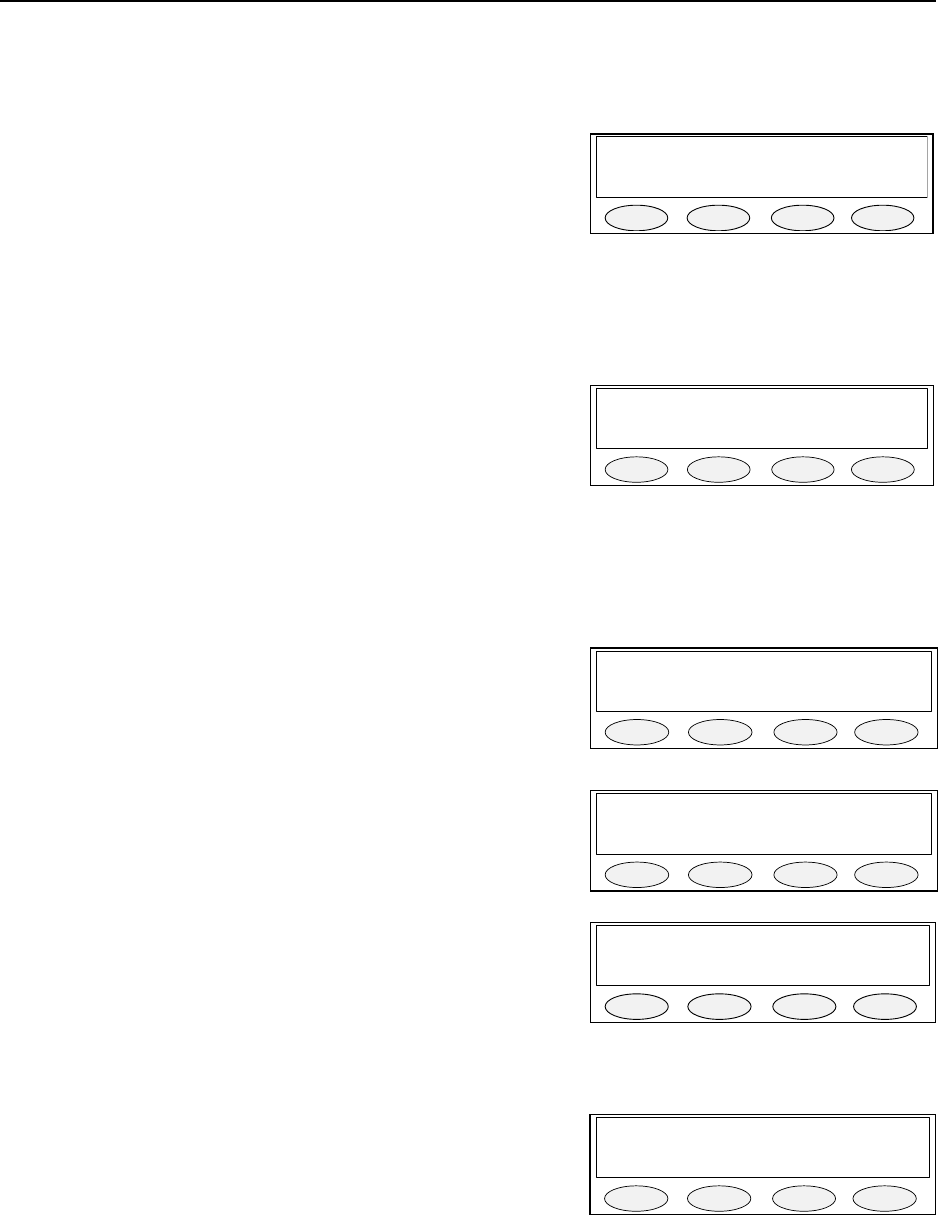
Remote Control Console 29
7.8.5 Dual Function Tone mode Screen
The Dual Function Tone screen is used when operating the C-2002 console with a DSP223 in the 99 Frequency
decode mode.
PROG1 – Toggles between Enable/Disabled.
PROG3 – Returns to Function tone screen.
PROG4 - Returns to the Opening menu screen.
7.9 Supervisor Enable
The supervisor function works in a manner similar to crossmute. It allows a single console to take control of all
selected lines by disabling transmit on all other attached consoles. See section 4.2.2 for information on the wiring
required to support this function. This function should only be enabled on consoles on which a supervisory function
is appropriate.
PROG2 - Disables Supervisory Capability.
PROG3 - Enables Supervisory Capability.
PROG4 - Return to top level menus.
7.10 Alert Programming
The following appears if the ALERT button is pressed while the Opening Menu Screen is showing. This screen
allows the technician to change the cadence of the alert tones. PROG1 selects between the two alert options. Alert
1 dictates which tone cadence will go out with the ALERT button. Alert 2 dictates which cadence will go out when
the ALT button plus ALRT button is configured as a second alert tone.
The PROG2 button scrolls through the available cadences
PROG1 - Selects between Alert 1 and Alert 2.
PROG2 – Selects Hi-Lo Warble or Steady Tone.
PROG3 - Allows editing of the level and frequency for the constant alert tone.
PROG4 - return to the Opening Menu Screen.
Cadence 1 is a steady programmable frequency.
Cadence 2 is a Hi-Lo Warble sound.
7.10.1 Cadence Level Selection
PROG1 - resets the level to the default of 0dBm.
PROG2 - decrements the level by 1 dBm.
PROG3 - increments the level by 1 dBm.
PROG4 - return to the Alert setup menu.
7.10.2 Cadence Frequency Selection
PROG1 - resets the frequency to the default value of 1000Hz.
PROG2 - decrements the frequency by 1Hz (min freq of 0Hz).
PROG3 - increments the frequency by 1Hz (max freq of 3500Hz).
PROG4 - return to Alert Tone setup screen.
DTMF keypad - may be used to program the frequency.
Dual Tone: DISABLED
T
g
l next back
PROG1 PROG2 PROG3 PROG4
Super: Enabled
p
rev next back
PROG1 PROG2 PROG3 PROG4
A
lert 1:1000Hz
A
1/2 Cad edit back
PROG1 PROG2 PROG3 PROG4
A
lert 1:1000Hz
Level Fre
q
back
PROG1 PROG2 PROG3 PROG4
Cad Lvl = 0dB
0dB dwn u
p
back
PROG1 PROG2 PROG3 PROG4
Cad Freq = 2050
1000H dwn u
p
back
PROG1 PROG2 PROG3 PROG4
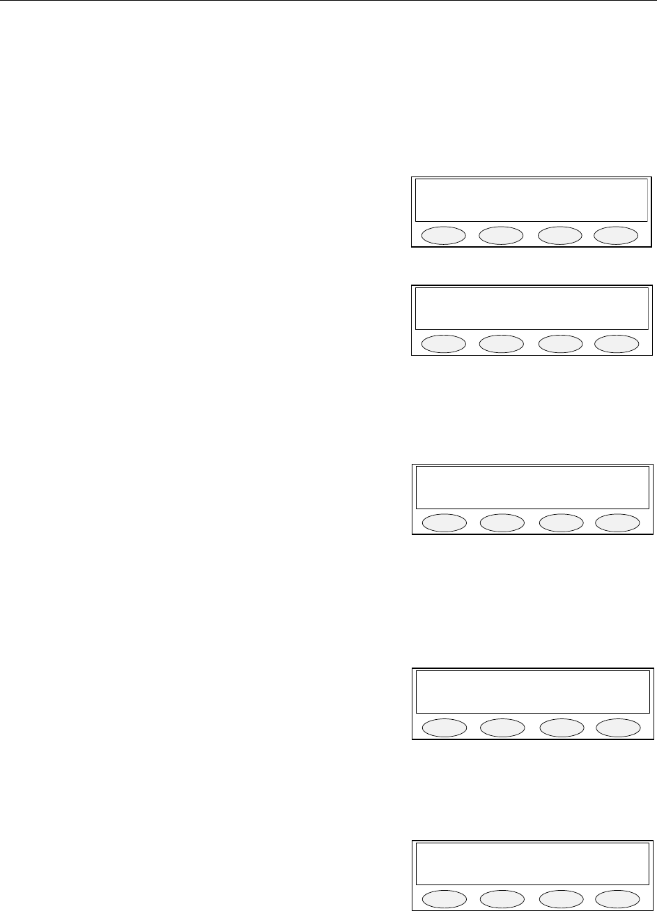
30 Vega’s C-2002
7.11 Monitor Programming Screen
The Monitor Programming Screen is displayed when the MON button is pressed while the display is on the
Opening Menu screen.
This screen allows the tone characteristics and whether a monitor tone burst shall automatically go out at the
beginning of every offhook condition to be configured. “Auto” is the default and means that a monitor tone burst
will go out every time the handset is taken off-hook. “Manual” means that a monitor tone burst will not go out with
every off-hook signal.
PROG1 - Go to Monitor Tone Characteristic Selection.
PROG2 - Selects between Auto and Manual mode.
PROG4 - Return to Opening Menu Screen.
7.11.1 Monitor Characteristic Selection
PROG1 - go to Monitor Frequency Screen.
PROG2 - go to Monitor Duration Screen.
PROG3 - go to Monitor Level Screen.
PROG4 - Return to Monitor Programming Screen.
7.11.1.1 Monitor Frequency
The Monitor burst normally consists of a 130ms guard tone and is followed by a 40ms monitor tone. In this screen
the frequency of the monitor function tone is set. The programmed frequency is displayed as the first of three
numbers. The default value is 2050Hz. The Up and Down buttons may be used to increment or decrement the
frequency in 1Hz increments. The DTMF keypad may also be used.
PROG1 - resets the frequency to the default value of 2050Hz.
PROG2 - decrements the frequency by 1Hz (min freq of 0Hz).
PROG3 - increments the frequency by 1Hz (max freq of 3500Hz).
PROG4 - return to Monitor Characteristic Screen.
DTMF keypad - may be used to program the frequency.
7.11.1.2 Monitor Duration
The Monitor burst normally consists of a 130ms guard tone and is followed by a 40ms monitor tone. In this screen
the duration of the monitor function tone is set. The programmed duration is displayed in milliseconds as the
second of three numbers. The default value is 40ms. The Up and Down buttons may be used to increment or
decrement the duration in 10ms increments.
PROG1 - resets the duration to the default value of 40ms.
PROG2 - decrements the duration by 10ms (minimum of 40ms).
PROG3 - increments the duration by 10ms (maximum of 500ms).
PROG4 - return to Monitor Characteristic Screen.
7.11.1.3 Monitor Level
The Monitor burst normally consists of a 130ms guard tone at +10dB and is followed by a 40ms monitor tone at
0dB. In this screen the level of the monitor function tone is set. The programmed level is displayed in dB as the
third of three numbers. The default value is 0dB. The Up and Down buttons may be used to increment or
decrement the level in 1dB increments. The displayed level shall change to reflect the new programming.
PROG1 - resets the level to the default value of 0dB.
PROG2 - decrements the duration by 1dB (minimum of -20dB).
PROG3 - increments the duration by 1dB (maximum of 10dB).
PROG4 - return to Monitor Characteristic Screen.
M
onitor Auto
Tone A/M back
PROG1 PROG2 PROG3 PROG4
M
on 2050/040/0
Fre
q
Dur Lvl back
PROG1 PROG2 PROG3 PROG4
M
on Freq = 2050
2050H dwn u
p
back
PROG1 PROG2 PROG3 PROG4
M
on Dur = 40ms
40ms dwn u
p
back
PROG1 PROG2 PROG3 PROG4
M
on Lvl = 0dB
0dB dwn u
p
back
PROG1 PROG2 PROG3 PROG4

Remote Control Console 31
Section Parameter Default Programmed
7.4.4.1 PIN Number
4.2.4 Line 1 2 or 4 Wire mode 4 wire
4.2.5 Line 1 RX Impedance 600 ohms
4.2.6 Line 1 TX Impedance 600 ohms
4.3.3 Line 1 RX Input Level 0dbm
7.3.1.2.1 Line 1 LAM-S Release 7 seconds
7.3.1.2.2 Line 1 LAM-S Trigger Level -10dbm
7.3.1.2.1 Line 1 LAM-U Release 7 seconds
7.3.1.2.2 Line 1 LAM-U Trigger Level -10dbm
7.6.1 Line 1 Enable/Disable Enable
7.6.2 Line 1 Tone/Local Tone
7.6.3 Line 1 Crossmute ON
7.6.4 Line 1 Squelch OFF
7.6.5 Line 1 TX Monitor OFF
7.6.6 Line 1 RX AGC ON
7.6.7 Line 1 TX Enable Enabled
7.6.8 Line 1 Unselect Lock Unlocked
4.2.4 Line 2 2 or 4 Wire mode 4 wire
4.2.5 Line 2 RX Impedance 600 ohms
4.2.6 Line 2 TX Impedance 600 ohms
4.3.3 Line 2 RX Input Level 0dbm
7.3.1.2.1 Line 2 LAM-S Release 7 seconds
7.3.1.2.2 Line 2 LAM-S Trigger Level -10dbm
7.3.1.2.1 Line 2 LAM-U Release 7 seconds
7.3.1.2.2 Line 2 LAM-U Trigger Level -10dbm
7.6.1 Line 2 Enable/Disable Enable
7.6.2 Line 2 Tone/Local Tone
7.6.3 Line 2 Crossmute ON
7.6.4 Line 2 Squelch OFF
7.6.5 Line 2 TX Monitor OFF
7.6.6 Line 2 RX AGC ON
7.6.7 Line 2 TX Enable Enabled
7.6.8 Line 2 Unselect Lock Unlocked
7.3.2.1.1 Desk Mic Gain 0dbm
7.3.2.1.2 Handset Mic Gain 0dbm
7.3.2.1.3 AUX input Gain 0dbm
7.3.2.2.1 Min. SPKR level 0dbm
7.3.2.3.1 TX Audio output level 0dbm
7.4.3.1.1.1 DTMF output Level 0dbm
7.4.3.1.1.2 DTMF Hold timer 500 msec
7.4.3.1.1.3 DTMF Keypad Enable Enabled
7.4.3.1.1.4 DTMF Generates PTT Enabled
Section Parameter Default Programmed
7.4.3.1.1.5 DTMF Select Call Timer 7 sec
7.4.3.1.2.1 Guard/Func/Hold Levels 10/0/-20
7.4.3.1.2.2 Guard/Hold Frequency 2175HZ

32 Vega’s C-2002
7.4.3.1.2.3 Guard Duration 130msec
7.4.3.1.2.3 Hold Duration 200msec
7.4.4.2 TX Delay 0msec
7.4.5.1 Unselect Audio Mute OFF
7.4.5.2 Duplex Disabled
7.4.6.1 Mic AGC ON
7.4.6.2 Handset Port Disabled
7.5.1.1 Alphanumeric L1-F1
7.5.1.1 Alphanumeric L1-F2
7.5.1.1 Alphanumeric L1-F3
7.5.1.1 Alphanumeric L1-F4
7.5.1.1 Alphanumeric L1-F5
7.5.1.1 Alphanumeric L1-F6
7.5.1.1 Alphanumeric L1-F7
7.5.1.1 Alphanumeric L1-F8
7.5.1.1 Alphanumeric L1-F9
7.5.1.1 Alphanumeric L1-F10
7.5.1.1 Alphanumeric L1-F11
7.5.1.1 Alphanumeric L1-F12
7.5.1.1 Alphanumeric L1-F13
7.5.1.1 Alphanumeric L1-F14
7.5.1.1 Alphanumeric L1-F15
7.5.1.1 Alphanumeric L1-F16
7.5.1.1 Alphanumeric L2-F1
7.5.1.1 Alphanumeric L2-F2
7.5.1.1 Alphanumeric L2-F3
7.5.1.1 Alphanumeric L2-F4
7.5.1.1 Alphanumeric L2-F5
7.5.1.1 Alphanumeric L2-F6
7.5.1.1 Alphanumeric L2-F7
7.5.1.1 Alphanumeric L2-F8
7.5.1.1 Alphanumeric L2-F9
7.5.1.1 Alphanumeric L2-F10
7.5.1.1 Alphanumeric L2-F11
7.5.1.1 Alphanumeric L2-F12
7.5.1.1 Alphanumeric L2-F13
7.5.1.1 Alphanumeric L2-F14
7.5.1.1 Alphanumeric L2-F15
7.5.1.1 Alphanumeric L2-F16
Section Parameter Default Programmed
7.8.1 F1 Enable/Disable Enable
7.8.2 F1-A Frequency 1950HZ
7.8.4 F1-A Duration 40 msec
7.8.1 F2 Enable/Disable Enable
7.8.2 F2-A Frequency 1850HZ
7.8.4 F2-A Duration 40 msec
7.8.1 F3 Enable/Disable Enable

Remote Control Console 33
7.8.2 F3-A Frequency 1750HZ
7.8.4 F3-A Duration 40 msec
7.8.1 F4 Enable/Disable Enable
7.8.2 F4-A Frequency 1650HZ
7.8.4 F4-A Duration 40 msec
7.8.1 F5 Enable/Disable Enable
7.8.2 F5-A Frequency 1550HZ
7.8.4 F5-A Duration 40 msec
7.8.1 F6 Enable/Disable Enable
7.8.2 F6-A Frequency 1450HZ
7.8.4 F6-A Duration 40 msec
7.8.1 F7 Enable/Disable Enable
7.8.2 F7-A Frequency 1350HZ
7.8.4 F7-A Duration 40 msec
7.8.1 F8 Enable/Disable Enable
7.8.2 F8-A Frequency 1250HZ
7.8.4 F8-A Duration 40 msec
7.8.1 F9 Enable/Disable Enable
7.8.2 F9-A Frequency 1150HZ
7.8.4 F9-A Duration 40 msec
7.8.1 F10 Enable/Disable Enable
7.8.2 F10-A Frequency 1050HZ
7.8.4 F10-A Duration 40 msec
7.8.1 F11 Enable/Disable Enable
7.8.2 F11-A Frequency 1950HZ
7.8.4 F11-A Duration 40 msec
7.8.1 F12 Enable/Disable Enable
7.8.2 F12-A Frequency 1850HZ
7.8.4 F12-A Duration 40 msec
7.8.1 F13 Enable/Disable Enable
7.8.2 F13-A Frequency 1750HZ
7.8.4 F13-A Duration 40 msec
7.8.1 F14 Enable/Disable Enable
7.8.2 F14-A Frequency 1650HZ
7.8.4 F14-A Duration 40 msec
Section Parameter Default Programmed
7.8.1 F15 Enable/Disable Enable
7.8.2 F15-A Frequency 1550HZ
7.8.4 F15-A Duration 40 msec
7.8.1 F16 Enable/Disable Enable
7.8.2 F16-A Frequency 1450HZ
7.8.4 F16-A Duration 40 msec
7.8.5 Dual Function Tone mode OFF
7.9 Supervisor Enable Disabled
7.10 Mute Button MON/TIMED Momentary Momentary/Timed____Sec
7.7.2 DTMF Incoming Select Call Empty
7.10 Alert Tone 1 Frequency 1000HZ

34 Vega’s C-2002
7.10 Alert Tone 1 Level 0dbm
7.10 Alert Tone 2 Frequency 1000HZ
7.10 Alert Tone 2 Level 0dbm
7.11.1 Monitor Tone Auto/Manual Manual
7.11.1.1 Monitor Frequency 2050HZ
7.11.1.2 Monitor Duration 40 msec
7.11.1.3 Monitor Level 0dbm
8 Technical Documentation
8.1 C-2002 Main Board, P/N 879583
8.1.1 Schematic
8.1.2 Bill of Material, component layout
8.2 C-2002 Keypad Board, P.N. 879573
8.2.1 Schematic
8.2.2 Bill of Material, component layout
8.3 C-2002 Top Assembly, P.N. 879592
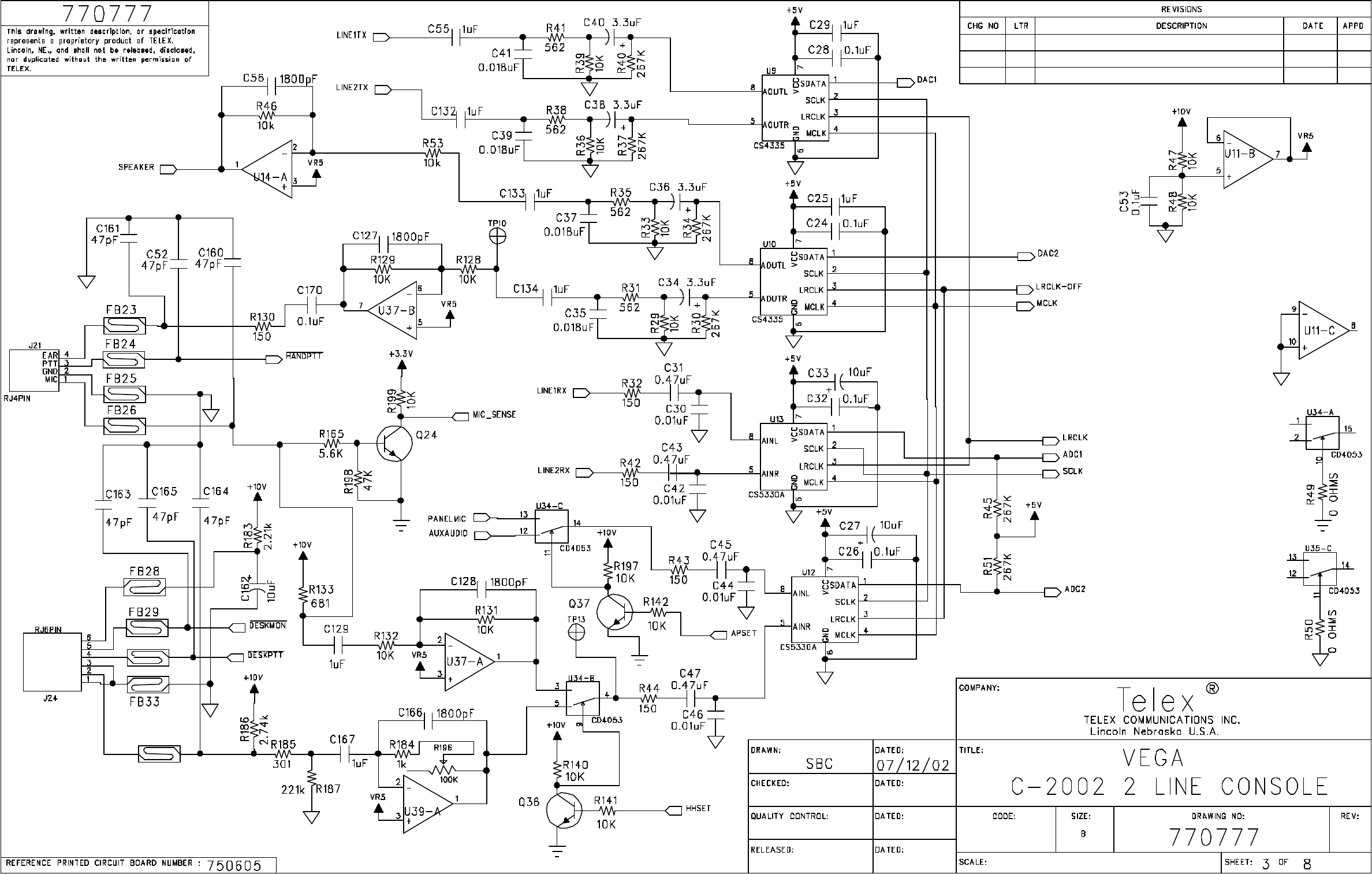
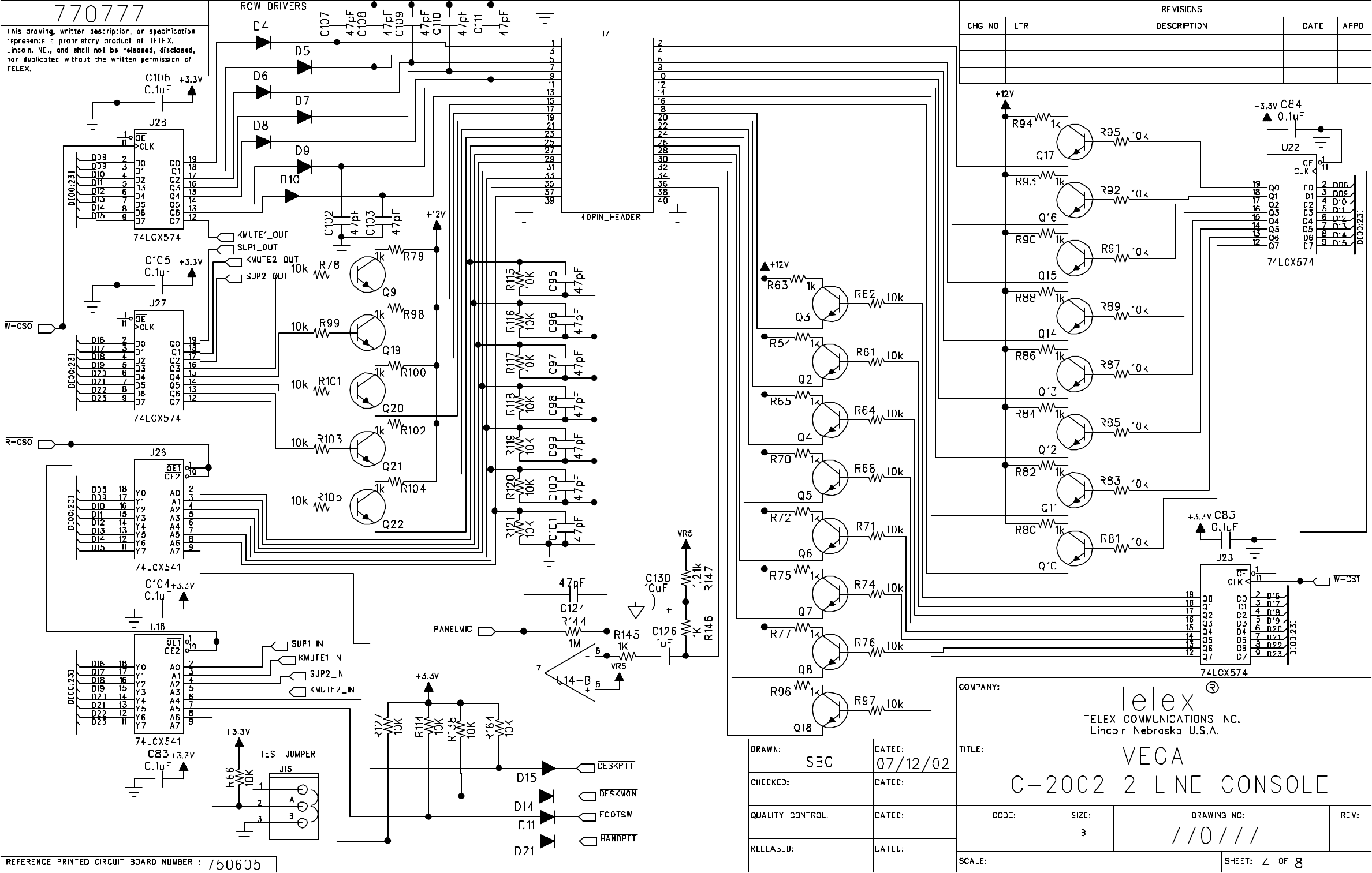
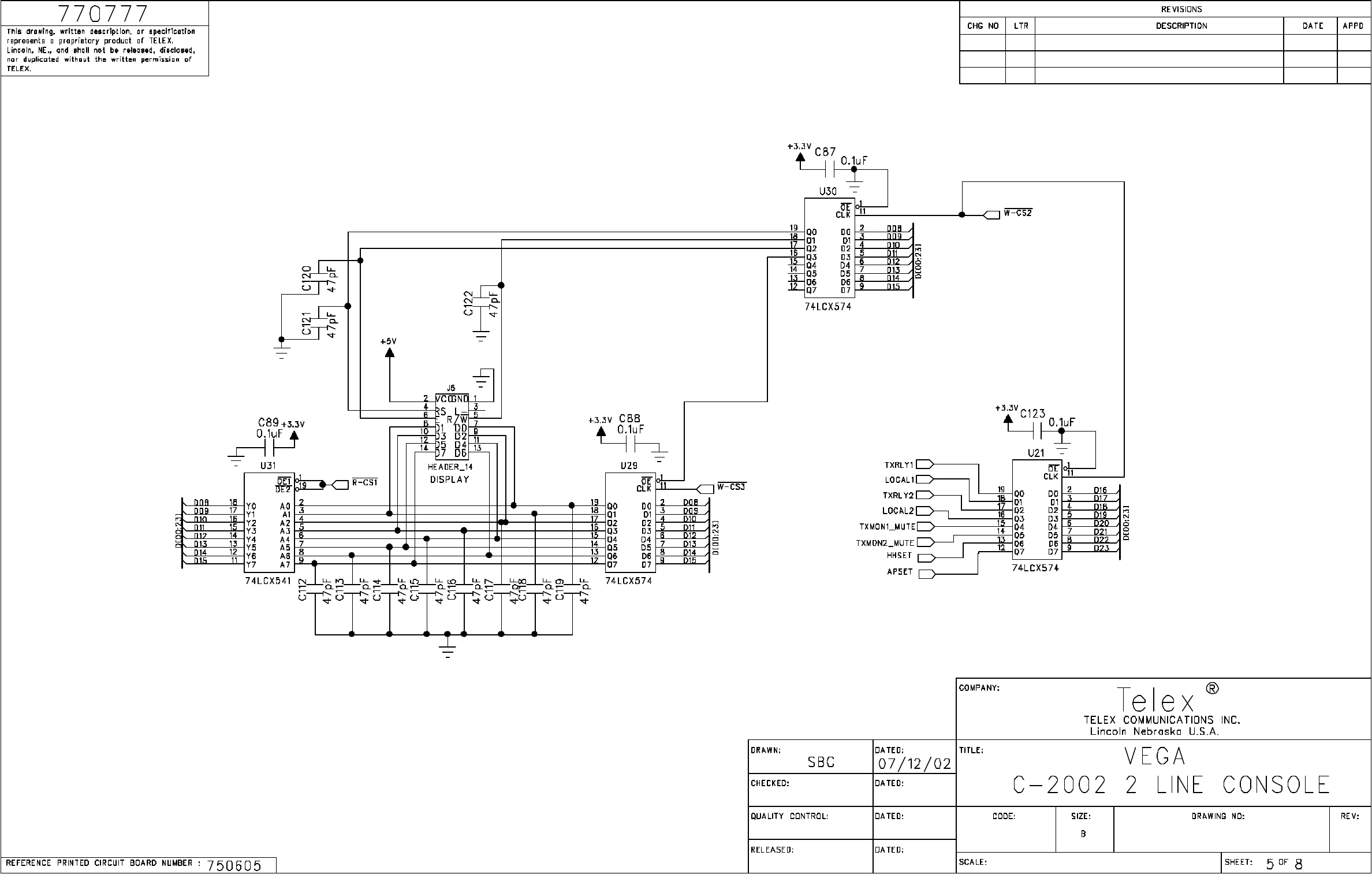
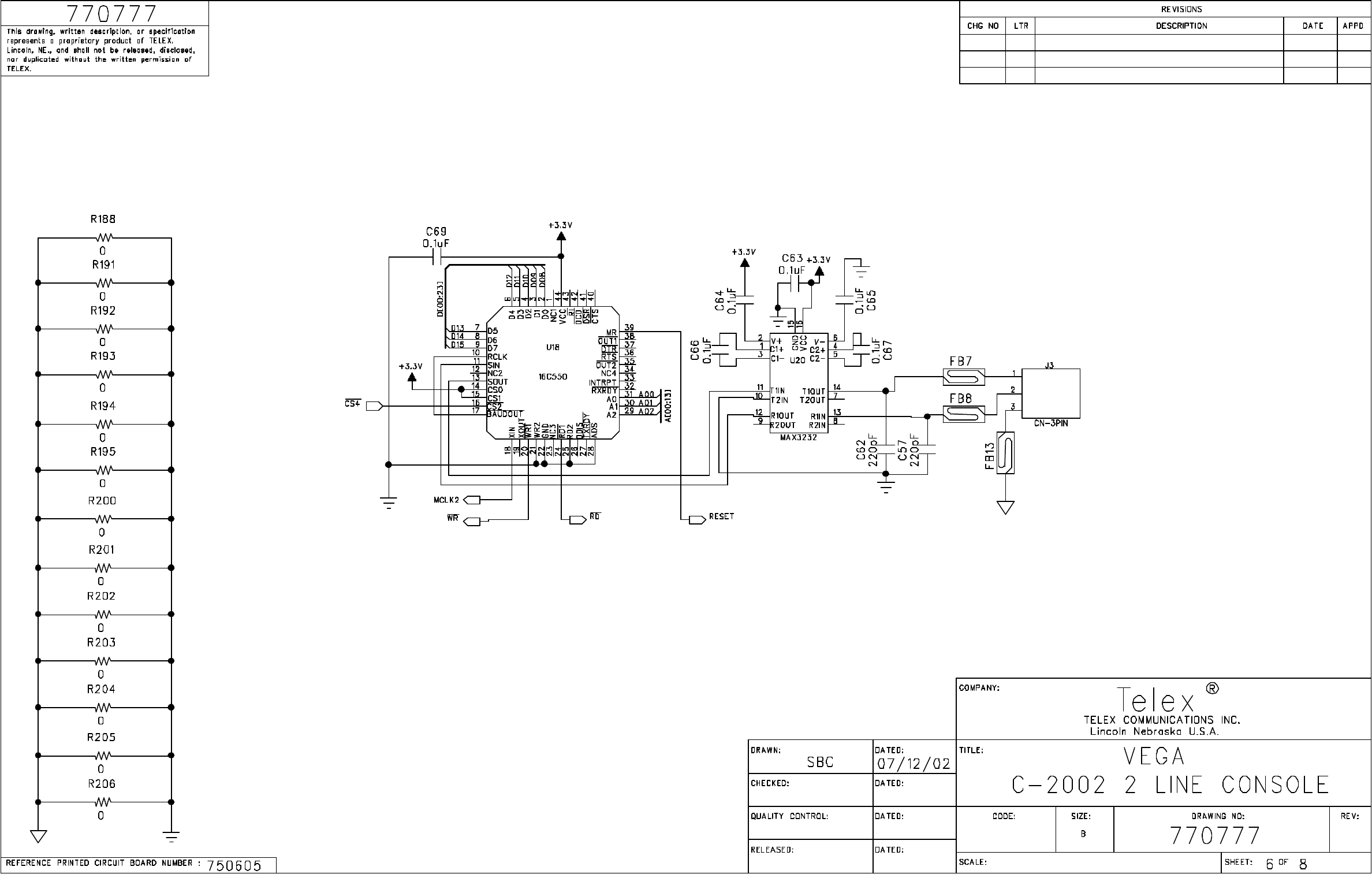
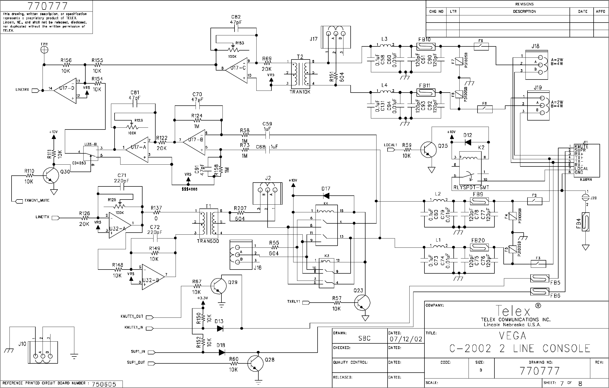
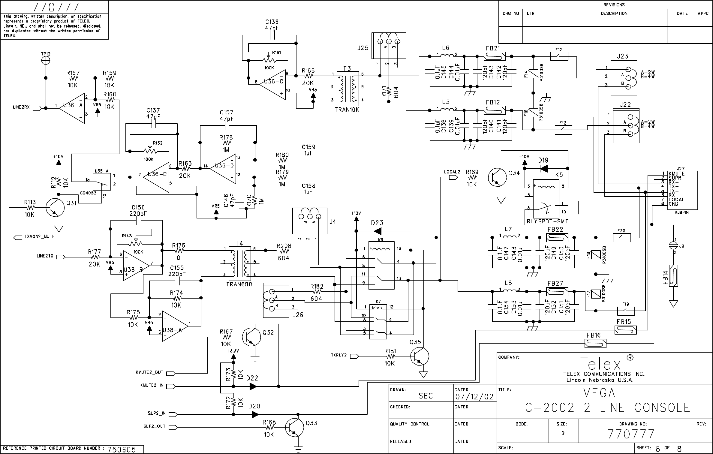
C2002 Hw Revision History.doc
REVISIONS
RE
V
DESCRIPTION ECO NO DATE
A
PPD
103/04/02
2
A
DDED FB3, C54, C172 ,C173 J2, J4, R207, R208, TP12, TP1
3
5/31/02
A
DDED R209, R210, R211, R212, R213, R214, R215, R21
6
A
DDED ITEM 93 - JUMPER CAPS
3 ITEM 13 CHANGED TO QTY 16, ITEM 14 CHANGED QTY TO 40 07/12/02
ITEM 23 CHANGED TO QTY 29, ITEM 52 CHANGED QTY TO 24
ITEM 64 CHANGED TO QTY 24, ITEM 67 CHANGED QTY TO 6
ITEMS 45, 46, 62, 63 DELETED
ITEM 94 ADDED, ITEM 23 CHANGED QTY TO 1, PCB TO REV B
This drawing, written description or specification Is
a proprietary product of TELEX, Lincoln, NE, and
shall not be released, disclosed, nor duplicated
without the written permission of TELEX.
Telex Communications INC.
Lincoln, Nebraska USA
APPROVALS: DR BY: SBC
DATE: 03/04/2002
PROD:CHKD BY: APPD BY:
879583
REV LEVEL:
PCB ASSY, C-2002 MAIN BOARD
TITLE:
PART NO:
3
LN,BE PAGE 1 OF 5
ITEM
NEW
QTY
TYPE DESCRIPTION PART NO. DESIGNATOR
1 1 BATTERY 3V COIN LEADED 724023 B1
2 51 CAP 0.1UF 0805 102881186
C1 C2 C3 C4 C5 C6 C7 C8 C11 C12 C13 C14 C15
C16 C17 C20 C21 C22 C23 C24 C26 C28 C32 C50
C53 C58 C63 C64 C65 C66 C67 C69 C73 C80 C83
C84 C85 C86 C87 C88 C89 C104 C105 C106 C12
3
C131 C138 C145 C147 C154 C170
3 1 CAP 1000uF ELEC. H 51821526 C125
4 16 CAP 120PF 0805 102881100
C143 C90 C75 C61 C149 C150 C151 C152 C77
C92 C78 C76 C93 C140 C141 C142
5 8 CAP 1800PF 0805 72341140 C166 C127 C128 C169 C56 C54 C172 C17
3
6 4 CAP 0.018UF 0805 102881126 C35 C37 C39 C41
7 4 CAP 3.3UF TANT B 102877021 C38 C40 C34 C3
6
8 12 CAP 0.01UF 0805 102881150
C42 C74 C30 C139 C144 C60 C148 C153 C79 C9
4
C44 C46
9 4 CAP 0.47UF 1210 102881445 C45 C47 C43 C31
10 1 CAP 0.047UF 0805 102881185 C49
11 1 CAP 6PF 0603 102879805 C51
12 6 CAP 220PF 0805 102881103 C62 C155 C57 C156 C72 C71
13 16 CAP 1UF 0805 102881875
C68 C48 C29 C55 C126 C129 C132 C133 C134
C59 C158 C159 C167 C168 C25 C135
14 40 CAP 47PF 0805 72341121
C70 C52 C91 C95 C96 C97 C98 C99 C100 C101
C102 C103 C107 C108 C109 C110 C111 C112
C113 C114 C115 C116 C117 C118 C119 C120
C121 C122 C124 C136 C137 C146 C157 C160
C161 C163 C164 C165 C81 C82
15 8 CAP 10UF TANT B 102877065 C9 C10 C18 C19 C27 C33 C130 C16
2
16 1 LED LED RED 58680000 D1
17 2 DIODE SMD4004 16016481SMT D2 D3
18 19 DIODE MMBD914 58711000
D4 D5 D6 D7 D8 D9 D10 D11 D12 D13 D14 D15
D17 D18 D19 D20 D21 D22 D23
19 1 LFUSE 1.5 AMP 7101051 F1
20 8 FUSE F1250T 710109 F2 F3 F8 F9 F12 F13 F19 F20
21 8 FUSE SIDACTOR P3100SB 7101082 F4 F5 F6 F7 F14 F16 F17 F18
22 29 FERRITE FERRITE 0805 723511
FB1 FB2 FB7 FB8 FB9 FB10 FB11 FB12 FB13
FB20 FB21 FB22 FB23 FB24 FB25 FB26 FB27
FB28 FB29 FB30 FB32 FB33 FB3 FB4 FB5 FB6
FB14 FB15 FB16
23 1 CONN 14 PIN SMT 640125 J6
24 0.34 CONN 3 PIN THRU HOLE 2861772 J10 J25 J26 J4
25 2 CONN RJ-8 LOW PROFILE 640134 J11 J27
26 8 CONN 3 PIN SMT 640124 J15 J16 J17 J18 J19 J22 J23 J
2
27 1 CONN RJ-4 PIN 640123 J21
28 1 CONN RJ-6 PIN 59946000 J24
29 1 CONN 3 PIN RT ANGLE 2862050 J3
30 1 CONN POWER 2.5MM 59697000 J35
31 1 CONN 6 PIN RT ANGLE 2862056 J36
32 1 CONN 2 PIN LOCKING 2861922 J5
This drawin
g
, written description or specification Is
a proprietary product of TELEX, Lincoln, NE, and
shall not be released, disclosed, nor duplicated
without the written permission of TELEX.
Telex Communications INC.
Lincoln, Nebraska USA
APPROVALS: DR BY: SBC
DATE: 03/04/2002
PROD:CHKD BY: APPD BY:
879583
REV LEVEL:
PCB ASSY, C-2002 MAIN BOARD
TITLE:
PART NO:
3
LN,BE Page 2 of 5

ITEM
NEW
QTY
TYPE DESCRIPTION PART NO. DESIGNATOR
This drawin
g
, written description or specification Is
a proprietary product of TELEX, Lincoln, NE, and
shall not be released, disclosed, nor duplicated
without the written permission of TELEX.
Telex Communications INC.
Lincoln, Nebraska USA
APPROVALS: DR BY: SBC
DATE: 03/04/2002
PROD:CHKD BY: APPD BY:
879583
REV LEVEL:
PCB ASSY, C-2002 MAIN BOARD
TITLE:
PART NO:
3
33 1 CONN SMT 40 PIN 6401321 J7
34 2 RELAY RLYSPDT-SMT 730142 K2 K5
35 RELAY DPDT RELAY, SMT DO NOT PLACE K3 K7
36 2 RELAY RLYDPDT-TH 1800329 K4 K6
37 8 INDUCTOR 820UH 1812 723510 L1 L2 L3 L4 L5 L6 L7 L
8
38 35 TRANSISTOR MMBT3904 SOT-23 54671200
Q1 Q2 Q3 Q4 Q5 Q6 Q7 Q8 Q9 Q10 Q11 Q12
Q13 Q14 Q15 Q16 Q17 Q18 Q19 Q20 Q21 Q22
Q23 Q24 Q25 Q28 Q29 Q30 Q31 Q32 Q33 Q34
Q35 Q36 Q37
39 1 RES 1.3K 0805 102515211 R1
40 1 RES 61.9K 0805 102515376 R106
41 0 RES O OHMS DNP R108
42 7 POT-V-TH 100K VERT. ADJ T/H 723097 R123 R125 R143 R153 R161 R162 R19
6
43 7 RES 20K 0805 102515329 R126 R122 R163 R166 R177 R69 R19
0
44 1 RES 681 OHMS 0805 102515180 R133
45
46
47 17 RES 0 OHMS 0805 102506000
R137 R176 R188 R191 R192 R193 R194 R195
R200 R201 R202 R203 R204 R205 R206 R49 R50
48 1 RES 1.21K 0805 102515208 R147
49 1 RES 5.62K 0805 102515272 R165
50 9 RES 1MEG 0805 102506105 R170 R124 R178 R179 R180 R73 R158 R144 R5
8
51 6 RES 604 OHMS 0805 102515175 R171 R182 R55 R151 R207 R20
8
52 24 RES 47 OHMS 0805 102506470
R18 R21 R17 R22 R23 R26 R27 R28 R15 R24 R25
R19 R20 R16 R52 R56 R134 R135 R136 R217
R218 R219 R220 R221
53 1 RES 2.21K 0805 102515233 R183
54 1 RES 301 OHMS 0805 102515146 R185
55 1 RES 2.74K 0805 102515242 R186
56 1 RES 221K 0805 102515433 R187
57 1 RES 47K 0805 102506473 R198
58 100 RES 10K 0805 102515300
R2 R3 R4 R5 R6 R7 R8 R9 R10 R11 R12 R13 R14
R29 R33 R36 R39 R47 R48 R57 R59 R60 R66 R67
R109 R110 R111 R112 R113 R114 R115 R116
R117 R118 R119 R120 R121 R127 R128 R129
R131 R132 R138 R139 R140 R141 R142 R148
R149 R150 R152 R154 R155 R156 R157 R159
R160 R164 R167 R168 R169 R172 R173 R174
R175 R181 R197 R199 R81 R76 R95 R83 R97 R9
9
R85 R101 R78 R103 R87 R105 R74 R46 R53 R61
R62 R64 R68 R71 R89 R91 R92 R189 R209 R210
R211 R212 R213 R214 R215 R216
59 4 RES 562 OHMS 0805 102515172 R31 R35 R41 R3
8
60 7 RES 267K 0805 102515441 R34 R37 R40 R45 R51 R107 R3
0
61 5 RES 150 OHMS 0805 102515117 R43 R44 R130 R32 R4
2
62
63
LN,BE Page 3 of 5
ITEM
NEW
QTY
TYPE DESCRIPTION PART NO. DESIGNATOR
This drawin
g
, written description or specification Is
a proprietary product of TELEX, Lincoln, NE, and
shall not be released, disclosed, nor duplicated
without the written permission of TELEX.
Telex Communications INC.
Lincoln, Nebraska USA
APPROVALS: DR BY: SBC
DATE: 03/04/2002
PROD:CHKD BY: APPD BY:
879583
REV LEVEL:
PCB ASSY, C-2002 MAIN BOARD
TITLE:
PART NO:
3
64 24 RES 1K 0805 102515200
R70 R72 R75 R77 R79 R80 R82 R84 R86 R88 R90
R93 R94 R96 R98 R100 R102 R104 R54 R63 R65
R184 R145 R146
65 2 TRANSFORMER 42TM016 600:600 3180259 T1 T4
66 2 TRANSFORMER 42TL218 10K:10K 7302832 T2 T3
67 6 TP TEST POINT 2017001400 TP1 TP8 TP10 TP11 TP12 TP13
68 1 IC DSP2189M 760252 U1
69 3 IC TL084 SO16 4300047 U11 U17 U3
6
70 2 IC CS5330A 760264 U12 U13
71 5 IC NE5532AD8 760268 U14 U32 U37 U38 U3
9
72 3 IC 74LCX541 760256 U16 U26 U31
73 1 IC 16C550 760262 U18
74 1 FERRITE COMMON MODE 724039 U19
75 1 CRYSTAL 32.768MHZ 780186 U2
76 1 IC MAX3232 760349 U20
77 7 IC 74LCX574 760257 U21 U22 U23 U27 U28 U29 U3
0
78 1 IC TPA0211 760307 U24
79 1 IC DS1302 SO8 760266 U25
80 1 IC AT24C16 511336000 U3
81 2 IC CD4053B 53266123 U34 U3
5
82 1 SOCKET PLCC 32 PLCC 539030032 U4 SOCKET
83 X 1 IC 7032 PLD C-2002 7602679PS U5
84 1 SOCKET PLCC 44 PIN PLCC 539030044 U5 SOCKET
85 1 IC UA7805CKTE 760260 U6
86 1 IC UA7810CKTE 760275 U7
87 1 IC TPS70158 760306 U8
88 2 IC CS4335 760263 U9 U10
89 1 XTAL32768K MC405-32768K 780181 Y1
90 X 1 PCB PRINTED CIRCUIT BOAR
D
750605
91 A/R PASTE SOLDERPASTE BE738
92 0 REFERENCE SCHEMATIC
93 12 JUMPER CAP JUMPER CAP 2515001001 FOR J10 J25 J26 J4 J15 J16 J17 J18 J19 J22 J23 J2
94 X 30 RES 47 OHMS 0402 102514470
R222 R223 R224 R225 R226 R227 R228 R229
R230 R231 R232 R233 R234 R235 R236 R237
R238 R239 R240 R241 R242 R243 R244 R245
R246 R247 R248 R249 R250 R251
LN,BE Page 4 of 5
BNSF_RDC_Keypad.sch-1 - Fri Mar 22 13:11:05 2002
ITEM
NEW
QTY
TYPE DESCRIPTION PART NO. DESIGNATOR
1 21 LED 1206 SMT LED RED 760317
D1 D2 D3 D4 D5 D6 D7 D8 D9 D10 D11
D12 D13 D14 D15 D16 D17 D18 D19 D20
D21
2 1 CONN SMT,PCB MOUNT,40 PIN HEADER 6401321 J1
3 1 PANELMIC ELECTRET MIC 2490247 J2
4 X 1 PCB PRINTED CIRCUIT BOARD 750598
5 X 0 REFERENCE SCHEMATIC
6 A/R PASTE SOLDERPASTE BE738
This drawin
g
, written description or specification Is
a proprietary product of TELEX, Lincoln, NE, and
shall not be released, disclosed, nor duplicated
without the written permission of TELEX.
Telex Communications INC.
Lincoln, Nebraska USA
APPROVALS: DR BY: SBC
DATE: 01/24/02
PROD:CHKD BY:SBC
DATE:01/24/02
APPD BY:
879573
REV LEVEL:
PCB ASSY, BNSF RDC KEYPAD BOARD
TITLE:
PART NO:
1
LN,BE Page 2 of 4
Doug
Ehlers
Digitally signed
by Doug Ehlers
DN: cn=Doug
Ehlers, o=Telex,
ou=Vega
Engineering,
c=US
Date: 2002.04.30
14:43:10 -06'00'
Signatur
e invalid

Remote Control Console 35
9 Warranty, Service, Repair, and Comments
Important! Be sure the exact return address and a description of the problem or work to be done are
enclosed with your equipment.
Warranty (Limited)
All Telex Communications / Vega signaling products are guaranteed against malfunction due to defects in
materials and workmanship for three years, beginning at the date of original purchase. If such a malfunction
occurs, the product will be repaired or replaced (at our option) without charge during the three-year period,
if delivered to the Telex factory. Warranty does not extend to damage due to improper repairs, finish or
appearance items, or malfunction due to abuse or operation under other than the specified conditions, nor
does it extend to incidental or consequential damages. Some states do not allow the exclusion or limitation of
incidental or consequential damages, so the above limitation may not apply to you. This warranty gives the
customer specific legal rights, and there may be other rights which vary from state to state.
Factory Service Center
TELEX Communications, Inc.
Vega Signaling Products
8601 East Cornhusker Highway, Lincoln, Nebraska, 68507
Phone: (402) 465-7026 / (800) 752-7560 Fax: (402) 467-3279
E-mail: vega@telex.com, Web: www.vega-signaling.com
Claims
No liability will be accepted for damages directly or indirectly arising from the use of our materials or from
any other causes. Our liability shall be expressly limited to replacement or repair of defective materials.
Suggestions or Comments
We’d appreciate your input. Please send us your suggestions or comments concerning this manual, by fax
(402-467-3279) or e-mail them to: vega@telex.com
Visit our web site at www.vega-signaling.com
Technical Support:
email address: acttechsupport@us.telex.com
phone #: 1-800-898-6723

36 Vega’s C-2002
10 Specifications
Front panel controls
● MONITOR
● INTERCOM
● PTT button
● 16 digit DTMF keypad
● Volume control
● Parallel TX detect LED
● Frequency Selection
Features
Programmable Single or Dual function tones
2 or 4 wire per line (field Programmable)
Up to 100 Function tones
Simplex/full duplex (field Programmable)
Parallel Update
Alert tone
15 DTMF Memory Dials
Programmable squelch control
TX Monitor
Supervised Control
Crossmute (hardwire)
TX and RX notch filters
Special features
♦ External PTT
♦ External Audio Input
♦ External DC input
♦ Data port for Cloning C-2002 to C-2002
♦ External Speaker Output
♦ Panel Microphone
♦ Internal tuning via keypad
Three Simultaneous Microphones
● Handset/Headset,
● Panel Microphone
● Desk Microphone
Specifications
Sequential tone line input and output impedance:
Two-Wire: 600, or 10K ohms, jumper selectable, transformer isolated,
Four-Wire TX Line: 600 ohm, or 1Meg ohm, jumper selectable,
transformer isolated,
Four-Wire RX Line: 600 or 10K ohm jumper selectable, transformer
isolated,
Local Control keying: Relay rated at 1A at 125Vac, 3A at 40Vdc
Line Input Level: -40 dBm to +10 dBm. Adjustable.
Line Output Level: -20 dBm to +10 dBm into a 600-ohm line,
adjustable (high-level guard tone only).
Distortion: 3% maximum at full output.
Hum and Noise: 50 dB below operating levels.
Speaker (one): 3 in, 8 ohm, heavy-duty.
Amplifier Power: 2W maximum at 3% THD into an 8 ohm load or
equivalent.
Optional Handset Earpiece Level: Adjustable level independent of
speaker volume controls.
Audio Frequency Response: 61.5dB, 300 to 3000 Hz, except at the
transmit tone notch frequency.
Tone Frequencies: PTT/Guard 2175Hz or 2300Hz. The monitor and
frequency function tones are programmable from 400Hz to 3000Hz
at 50Hz increments. Accuracy 61 Hz.
Operating Temperature Range: 0 to +70 degree C.
Power Requirements: 117 Vac, 60Hz, 25W, or 12.0 Vdc at 1A
maximum.
Microphone Connection: Handset and Headset 4-wire; Desk uses 6-
wire.
Note: Specifications are subject to change with out notice.
