Telit Communications S p A CC864-DUAL Dual-Band CDMA Module/GPS User Manual GS10 GS15 UserManual en
Telit Communications S.p.A. Dual-Band CDMA Module/GPS GS10 GS15 UserManual en
Contents
- 1. User MAnual
- 2. Users Manual
- 3. User Manual
- 4. user manual
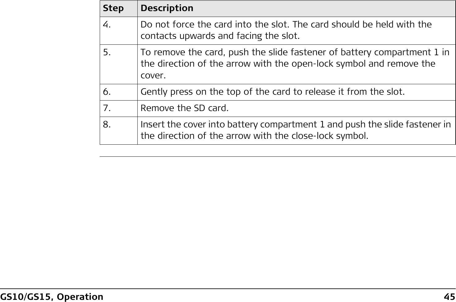
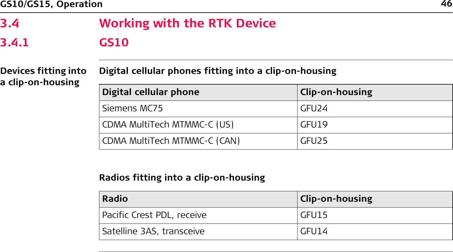
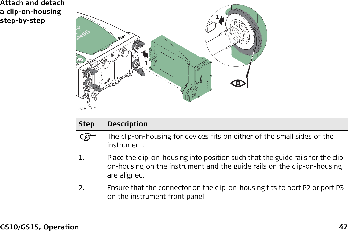
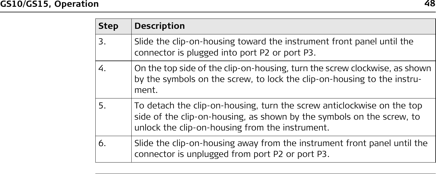
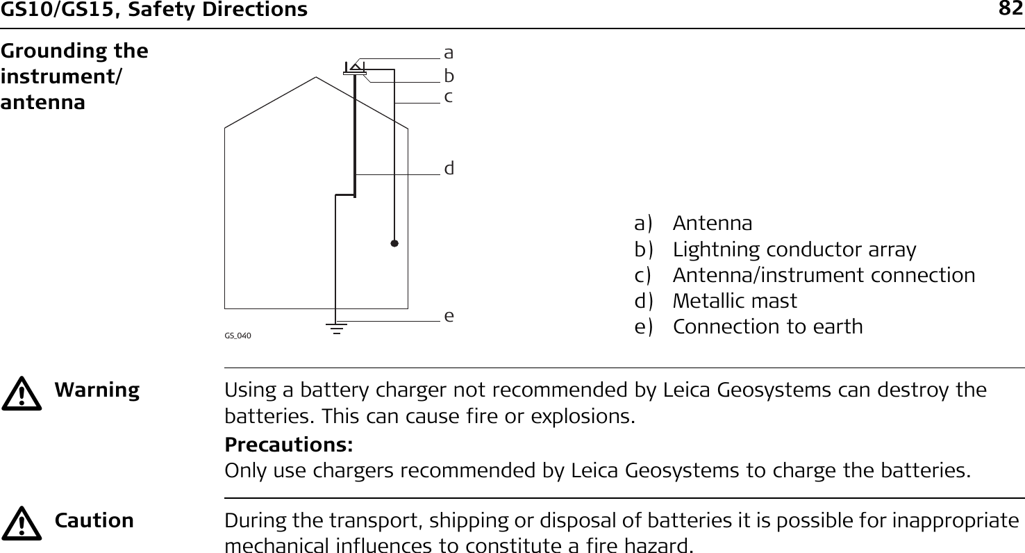
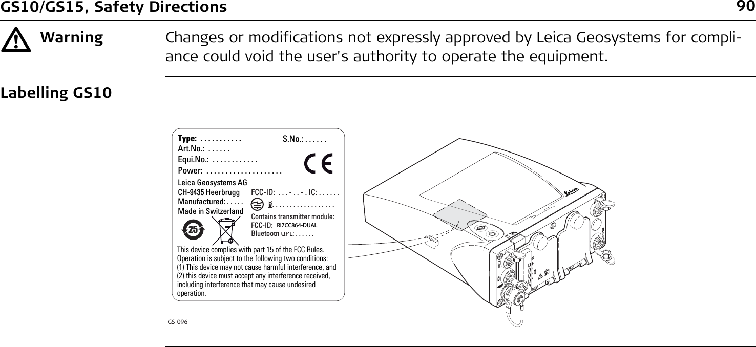
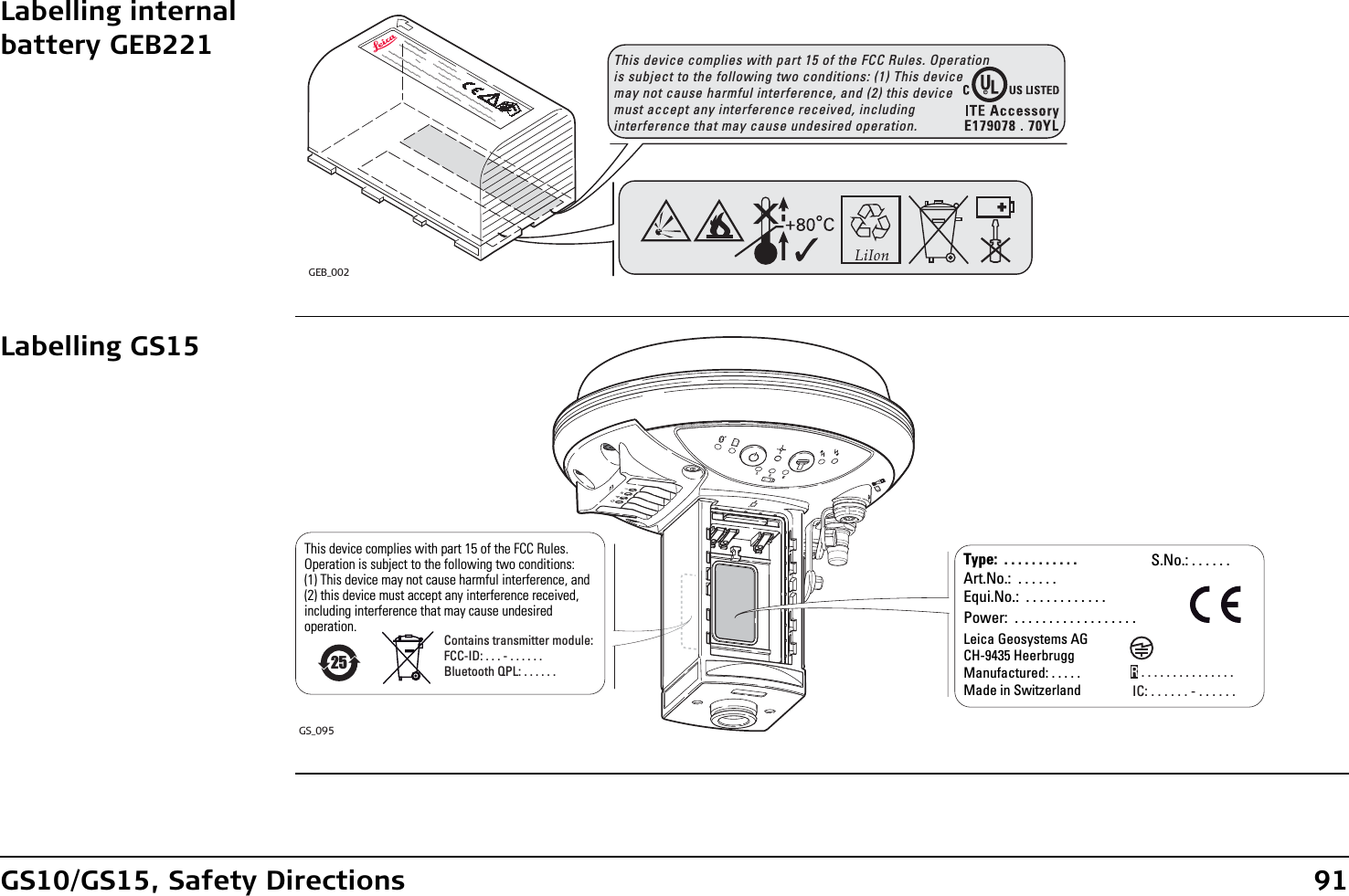
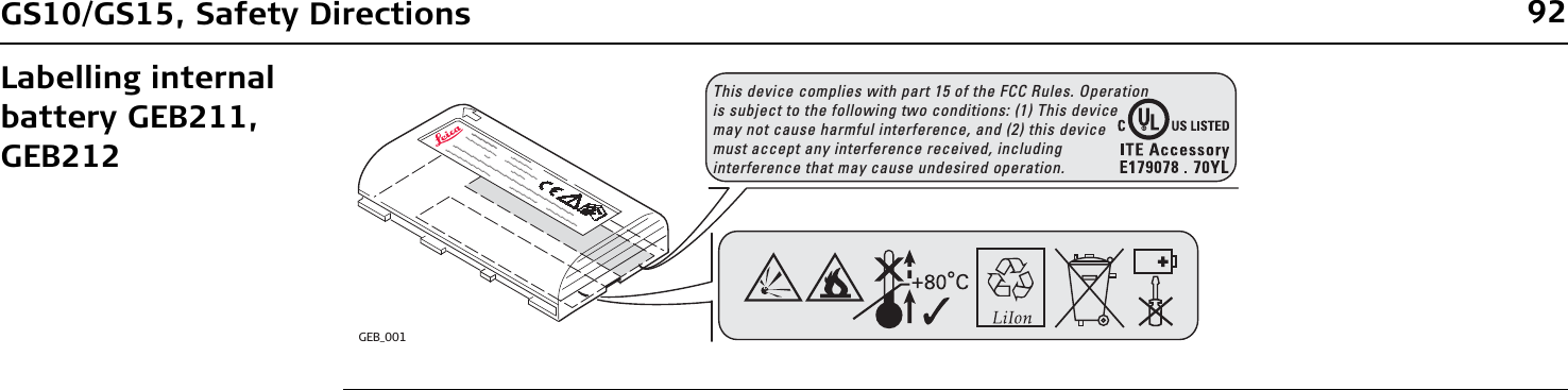
User Manual
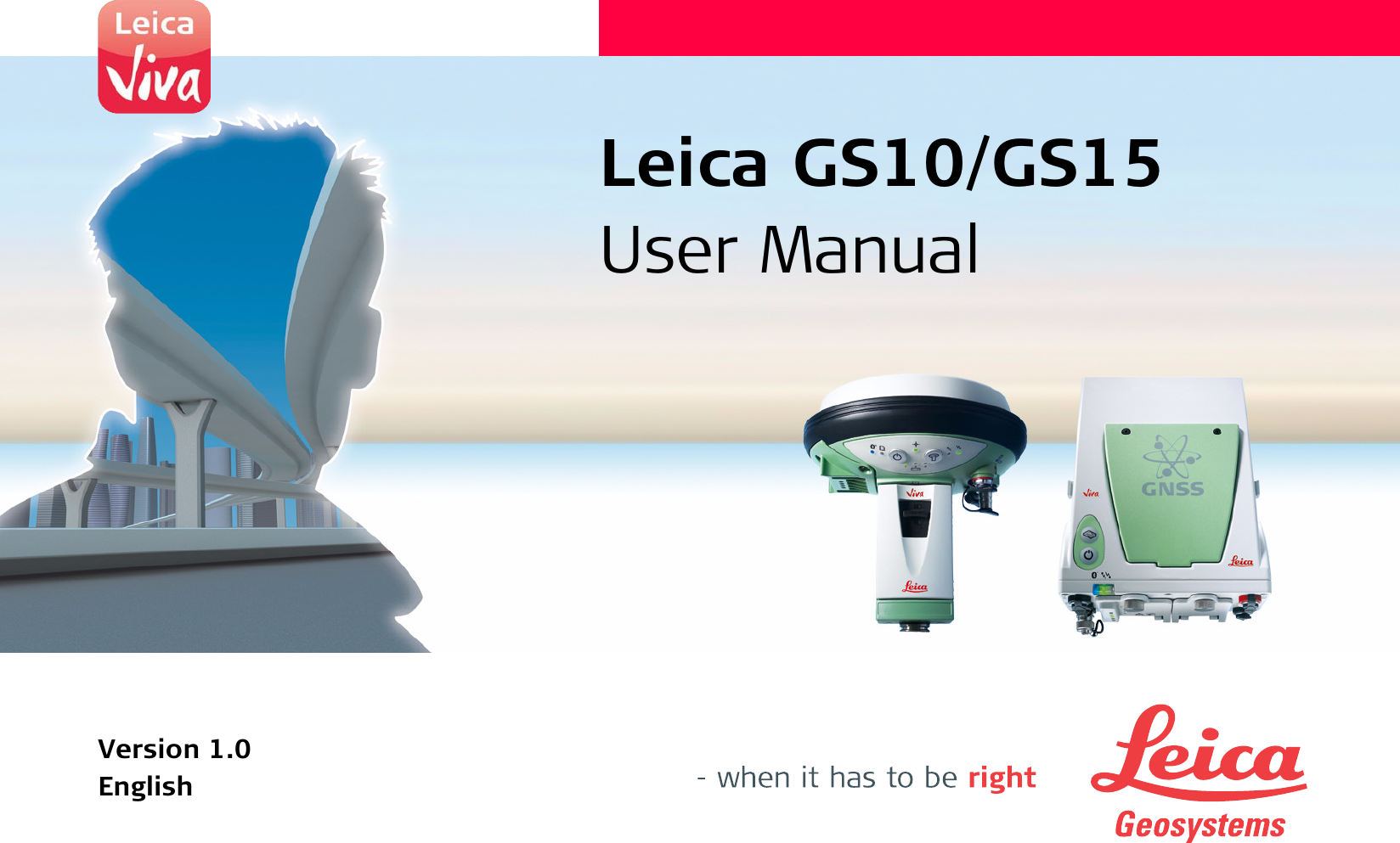
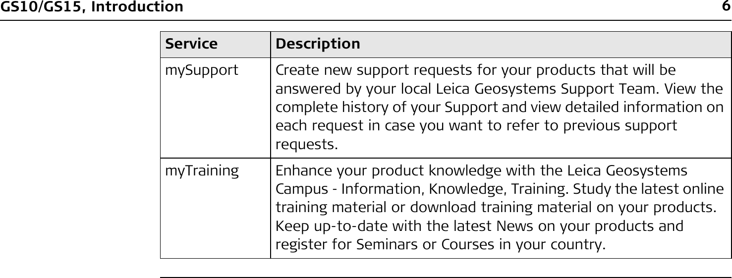
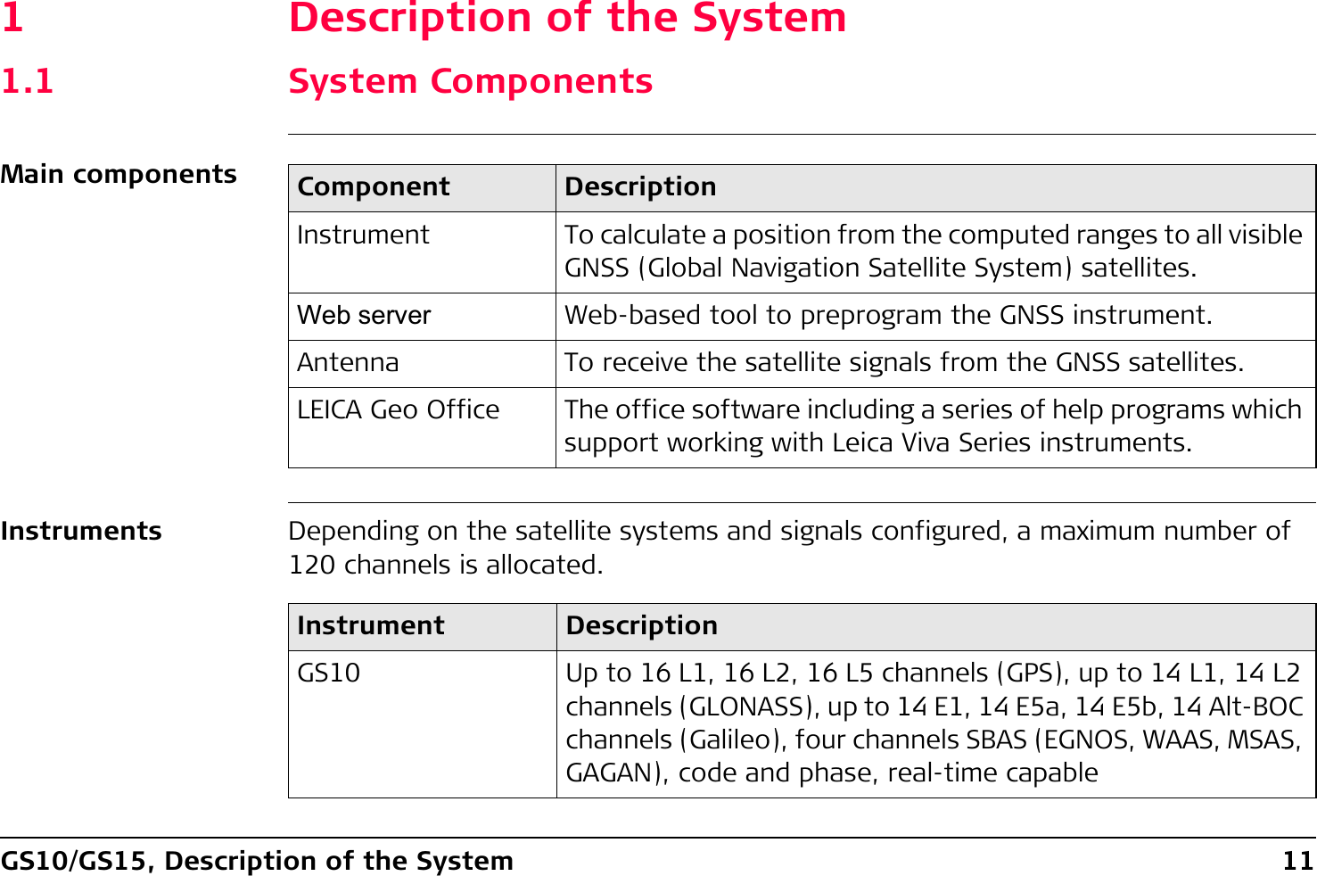

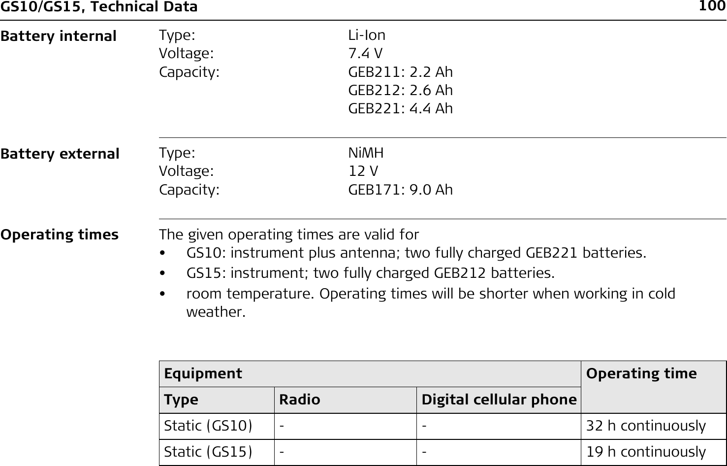
![98GS10/GS15, Technical Data6.1.3 Technical DataDimensions The dimensions are given for the housing without the sockets.Weight Instrument weights without battery and radio:Type Length [m] Width [m] Thickness [m]GS10 0.212 0.166 0.079Type Height [m] Diameter [m]GS15 0.198 0.196Type Weight [kg]/[lbs]GS10 1.20/2.65GS15 1.34/2.95](https://usermanual.wiki/Telit-Communications-S-p-A/CC864-DUAL.User-Manual/User-Guide-1250313-Page-98.png)
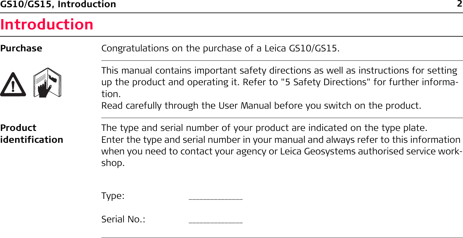
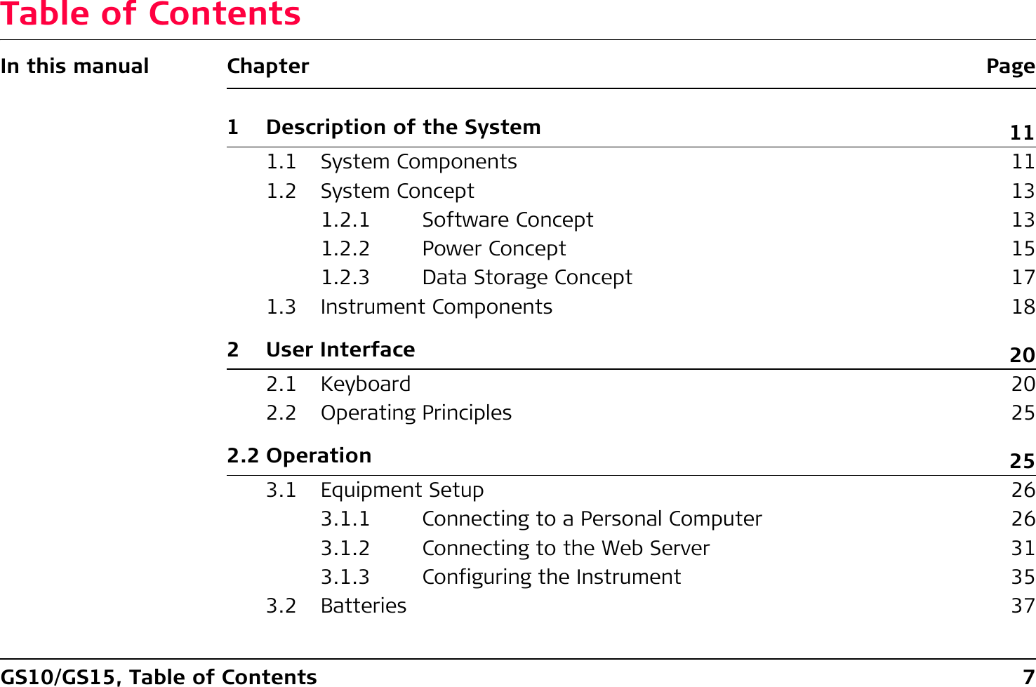
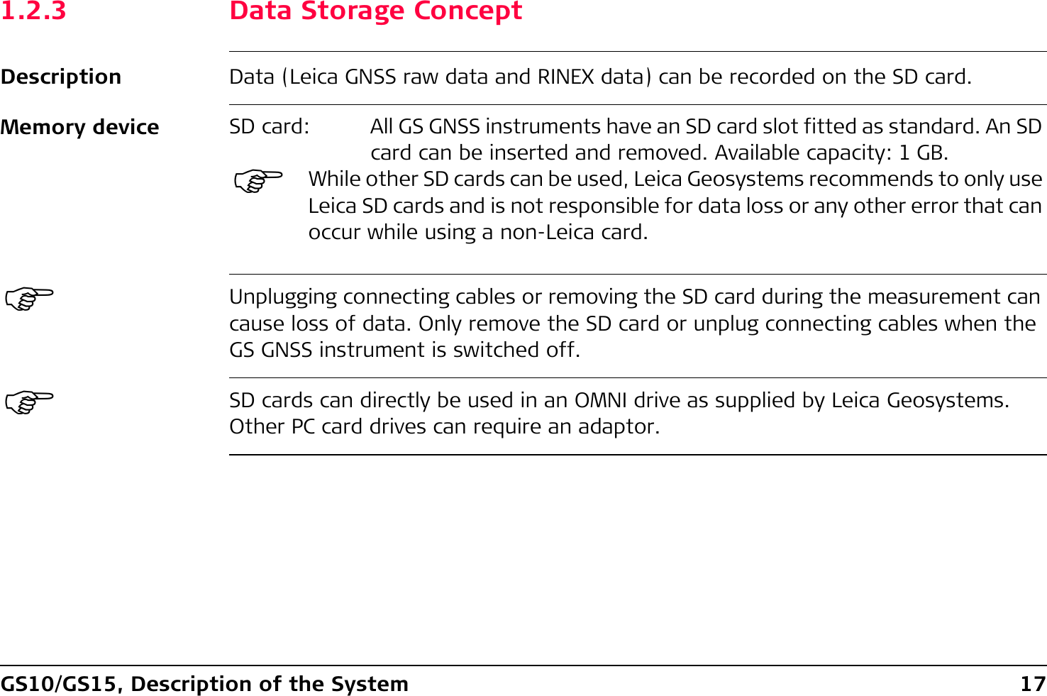
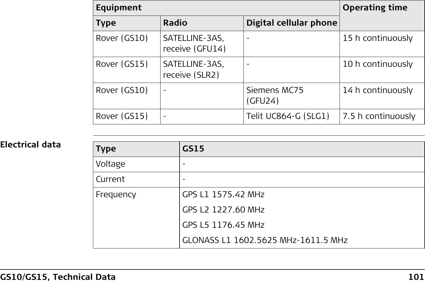
![GS10/GS15, Technical Data 99Recording Data (Leica GNSS raw data and RINEX data) can be recorded on the SD card.PowerType Capacity [MB] Data capacitySD card • 1024 1024 MB is typically sufficient for aboutGPS only (12 satellites)• 8000 h L1 + L2 + L5 data logging at 15 s rate• 32000 h L1 + L2 + L5 data logging at 60 s rate• 1440000 real-time points with codesGPS + GLONASS (12/8 satellites)• 6800 h data logging at 15 s rate• 27200 h data logging at 60 s rate• 1440000 real-time points with codesGPS + GLONASS + Galileo (12/8/10 satellites)• 3200 h data logging at 15 s rate• 12800 h data logging at 60 s rate• 1440000 real-time points with codesPower consumption: GS10/GS15, radio excluded: 3.2 W typically, 270 mAExternal supply voltage: Nominal 12 V DC ( , GEV71 car battery cable to a 12 V car battery), voltage range 10.5 V-28 V DC](https://usermanual.wiki/Telit-Communications-S-p-A/CC864-DUAL.User-Manual/User-Guide-1250313-Page-99.png)
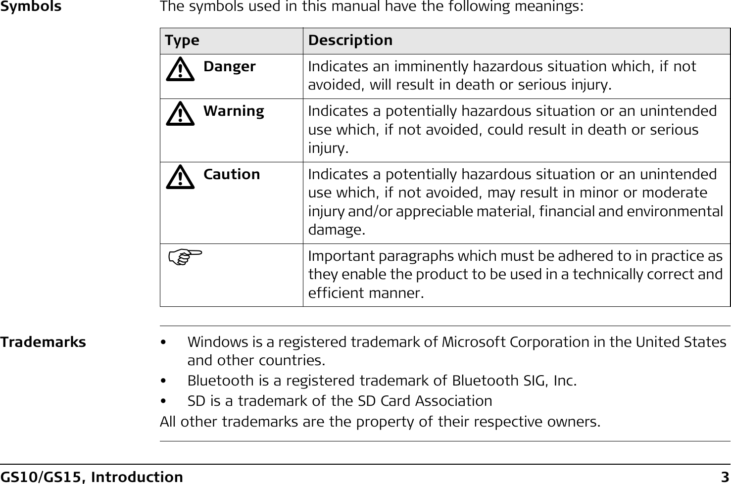
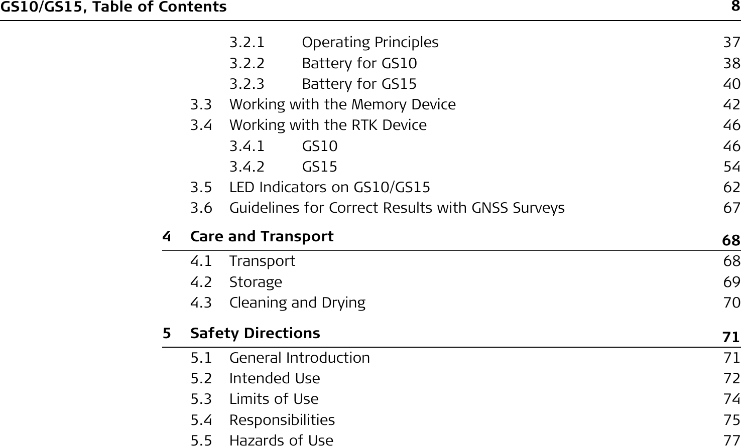
![102GS10/GS15, Technical Data)Galileo Alt-BOC covers bandwidth of Galileo E5a and E5b.Environmental specificationsTemperatureGLONASS L2 1246.4375 MHz-1254.3 MHzGalileo E1 1575.42 MHzGalileo E5a 1176.45 MHzGalileo E5b 1207.14 MHzGalileo Alt-BOC 1191.795 MHzGain Typically 27 dBiNoise Figure Typically < 2 dBiType GS15Type Operating temperature [°C] Storage temperature [°C]All instruments -40 to +65 -40 to +80Leica SD cards -40 to +80 -40 to +80Battery internal -20 to +55 -40 to +70](https://usermanual.wiki/Telit-Communications-S-p-A/CC864-DUAL.User-Manual/User-Guide-1250313-Page-102.png)
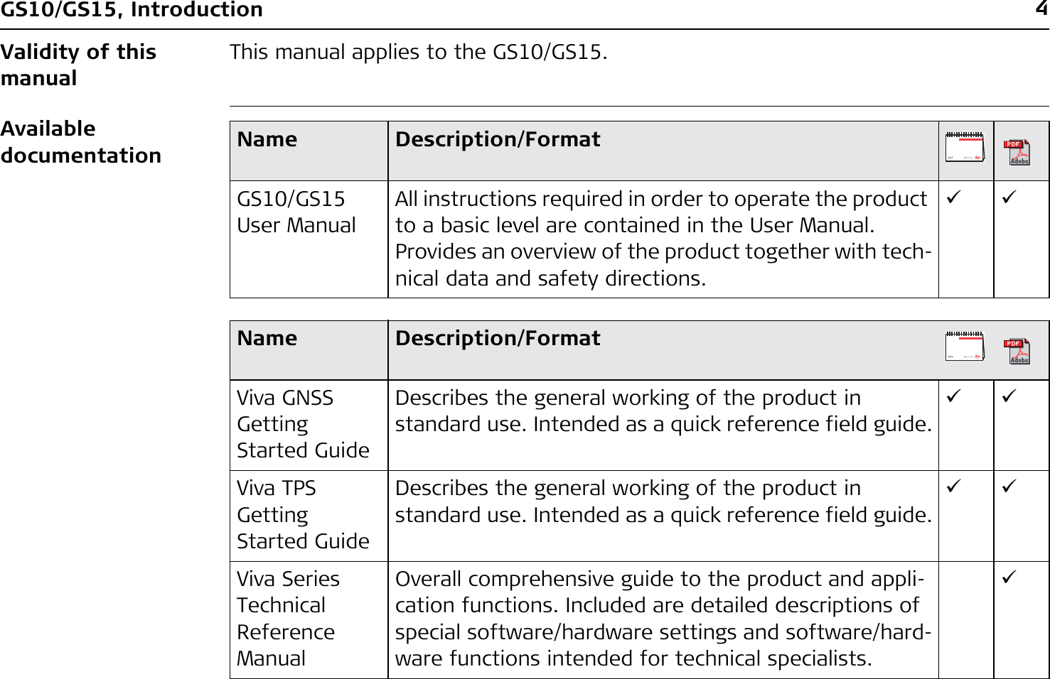
![GS10/GS15, Technical Data 107)Galileo Alt-BOC covers bandwidth of Galileo E5a and E5b.Environmental specificationsTemperatureGalileo E5a 1176.45 MHz-9-9Galileo E5b 1207.14 MHz-9-9Galileo Alt-BOC 1191.795 MHz-9-9Gain (typically) 27 dBi 29 dBi 29 dBi 40 dBiNoise Figure (typically)< 2 dBi < 2 dBi 3 dBi max < 1.2 dBi maxType AS05 AS10 AT504GG AR25Type Operating temperature [°C] Storage temperature [°C]AS05/AS10 -40 to +70 -55 to +85AT504GG -40 to +70 -40 to +70AR25 -55 to +85 -55 to +90](https://usermanual.wiki/Telit-Communications-S-p-A/CC864-DUAL.User-Manual/User-Guide-1250313-Page-107.png)
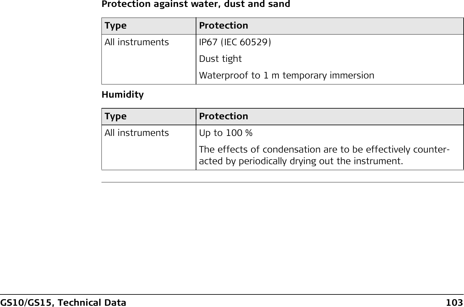
![108GS10/GS15, Technical DataProtection against water, dust and sandHumidityCable lengthType ProtectionAll antennas IP67 (IEC 60529)Dust tightProtected against water jetsWaterproof to 1 m temporary immersionType ProtectionAll antennas Up to 100 %The effects of condensation are to be effectively counter-acted by periodically drying out the antenna.Separation distance from instrument ...to antenna Supplied cable lengths [m]Optional cable lengths [m]GS10 AS05/AS10/AT504GG/AR251.22.810305070](https://usermanual.wiki/Telit-Communications-S-p-A/CC864-DUAL.User-Manual/User-Guide-1250313-Page-108.png)
![110GS10/GS15, Technical DataFrequency bandOutput powerType Frequency band [MHz]GS10 1176.451191.7951207.141227.601246.4375 - 1254.31575.421602.4375 - 1611.5Bluetooth 2402 - 2480Type Output power [mW]GNSS Receive onlyBluetooth 5](https://usermanual.wiki/Telit-Communications-S-p-A/CC864-DUAL.User-Manual/User-Guide-1250313-Page-110.png)
![GS10/GS15, Technical Data 111Antenna Type Antenna Gain [dBi] Connector Frequency band [MHz]GNSS External GNSS antenna element (receive only)-- -Bluetooth Internal Microstrip antenna1.5 - -](https://usermanual.wiki/Telit-Communications-S-p-A/CC864-DUAL.User-Manual/User-Guide-1250313-Page-111.png)
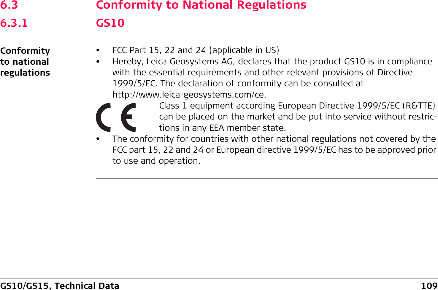
![112GS10/GS15, Technical Data6.3.2 GS15Conformity to national regulationsFrequency band• FCC Part 15, 22 and 24 (applicable in US)• Hereby, Leica Geosystems AG, declares that the product GS15 is in compliance with the essential requirements and other relevant provisions of Directive 1999/5/EC. The declaration of conformity can be consulted at http://www.leica-geosystems.com/ce.Class 1 equipment according European Directive 1999/5/EC (R&TTE) can be placed on the market and be put into service without restric-tions in any EEA member state.• The conformity for countries with other national regulations not covered by the FCC part 15, 22 and 24 or European directive 1999/5/EC has to be approved prior to use and operation.Type Frequency band [MHz]GS15 1176.451191.7951207.141227.601246.4375 - 1254.31575.421602.4375 - 1611.5](https://usermanual.wiki/Telit-Communications-S-p-A/CC864-DUAL.User-Manual/User-Guide-1250313-Page-112.png)
![GS10/GS15, Technical Data 113Output powerAntennaBluetooth 2402 - 2480Type Frequency band [MHz]Type Output power [mW]GNSS Receive onlyBluetooth 5Type Antenna Gain [dBi] Connector Frequency band [MHz]GNSS Internal GNSS antenna element (receive only)---Bluetooth Internal Microstrip antenna1.5 - -](https://usermanual.wiki/Telit-Communications-S-p-A/CC864-DUAL.User-Manual/User-Guide-1250313-Page-113.png)
![GS10/GS15, Technical Data 115AntennaSpecific Absorption Rate (SAR)The product meets the limits for the maximum permissible exposure of the guide-lines and standards which are force in this respect. The product must be used with the recommended antenna. A separation distance of at least 20 centimetres should be kept between the antenna and the body of the user or nearby person within the intended application.Type GAT 3 GAT 5Frequency band [MHz] 890 - 960 /1710 - 1880 /1920 - 2170824 - 894 /1850 - 1990Type Detachable λ/2 antenna Detachable λ/2 antennaConnector TNC TNC](https://usermanual.wiki/Telit-Communications-S-p-A/CC864-DUAL.User-Manual/User-Guide-1250313-Page-115.png)
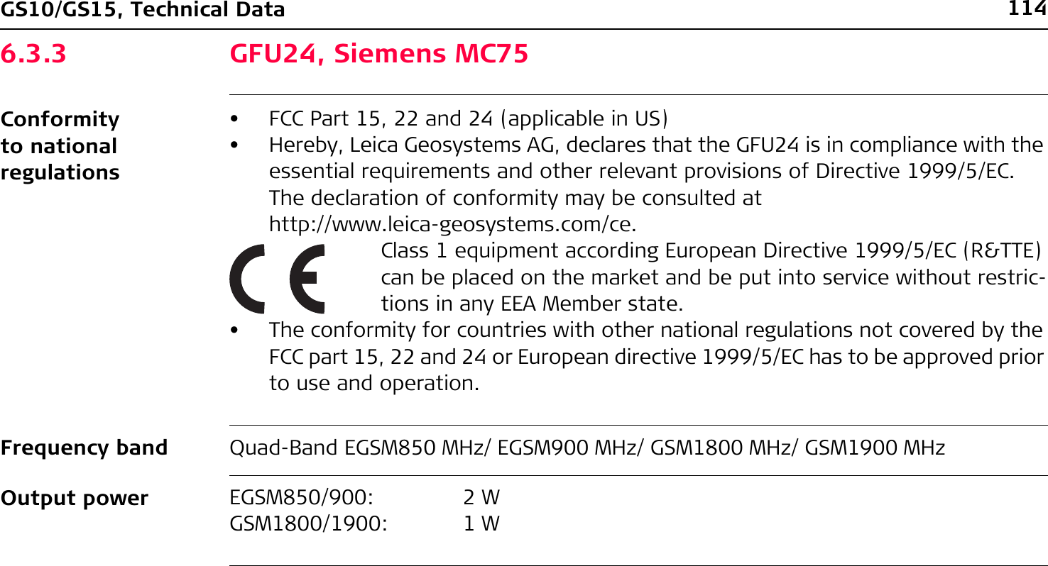
![116GS10/GS15, Technical Data6.3.4 GFU19 (US), GFU25 (CAN) CDMA MultiTech MTMMC-CConformity to national regulations• FCC Part 15, 22 and 24 (applicable in US)• The conformity for countries with other national regulations not covered by the FCC part 15, 22 and 24 has to be approved prior to use and operation.Frequency band Dual-Band CDMA850 MHz/CDMA1900 MHzOutput powerAntennaCDMA850: 2 WCDMA1900: 0.4 WType GAT 5Frequency band [MHz] 824 - 894 /1850-1990Type Detachable λ/2 antennaConnector TNC](https://usermanual.wiki/Telit-Communications-S-p-A/CC864-DUAL.User-Manual/User-Guide-1250313-Page-116.png)

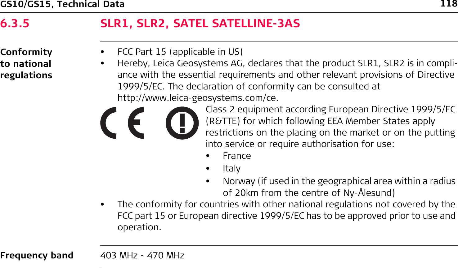
![GS10/GS15, Technical Data 119Output powerAntennaSpecific Absorption Rate (SAR)The product meets the limits for the maximum permissible exposure of the guide-lines and standards which are force in this respect. The product must be used with the recommended antenna. A separation distance of at least 20 centimetres should be kept between the antenna and the body of the user or nearby person within the intended application.SLR1: 0.5 W-1.0 WSLR2: Receive onlyType Internal GAT 1 GAT 2Frequency band [MHz] 400 - 470 400 - 435 435 - 470Type Internal Detachable λ/2 antennaDetachable λ/2 antennaConnector - TNC TNC](https://usermanual.wiki/Telit-Communications-S-p-A/CC864-DUAL.User-Manual/User-Guide-1250313-Page-119.png)
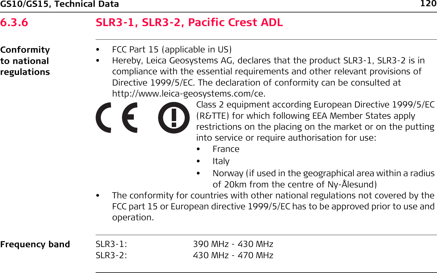
![GS10/GS15, Technical Data 121Output powerAntennaSpecific Absorption Rate (SAR)The product meets the limits for the maximum permissible exposure of the guide-lines and standards which are force in this respect. The product must be used with the recommended antenna. A separation distance of at least 20 centimetres should be kept between the antenna and the body of the user or nearby person within the intended application.SLR3-1: 0.5 W-1 WSLR3-2: 0.5 W-1 WType Internal GAT 1 GAT 2Frequency band [MHz] 400 - 470 400 - 435 435 - 470Type Internal Detachable λ/2 antennaDetachable λ/2 antennaConnector - TNC TNC](https://usermanual.wiki/Telit-Communications-S-p-A/CC864-DUAL.User-Manual/User-Guide-1250313-Page-121.png)
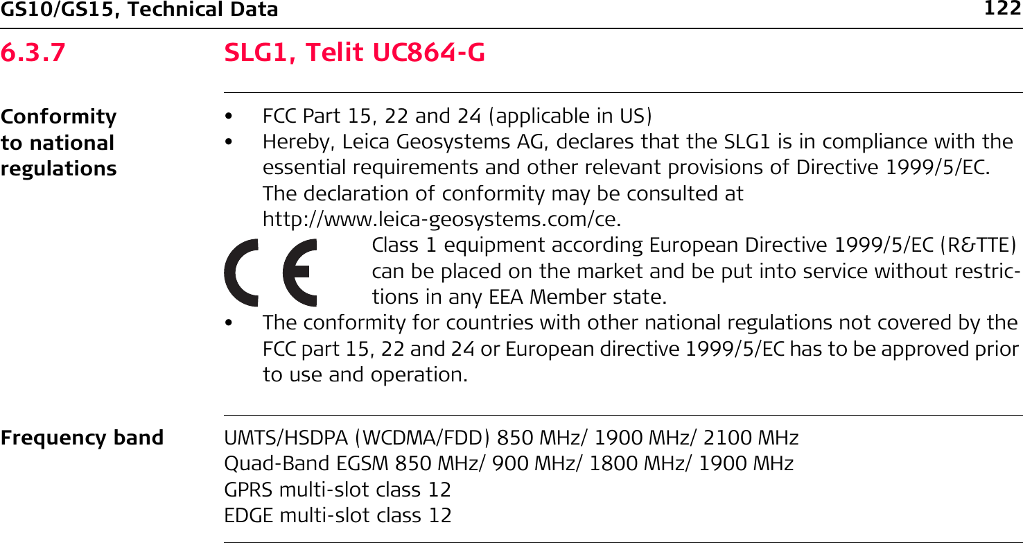
![GS10/GS15, Technical Data 123Output powerAntennaSpecific Absorption Rate (SAR)The product meets the limits for the maximum permissible exposure of the guide-lines and standards which are force in this respect. The product must be used with the recommended antenna. A separation distance of at least 20 centimetres should be kept between the antenna and the body of the user or nearby person within the intended application.EGSM850/900: 2 WGSM1800/1900: 1 WUMTS2100: 0.25 WEDGE850/900: 0.5 WEDGE1800/1900: 0.4 WType Internal GAT 3 GAT 5Frequency band [MHz] 824 - 894 /890 - 960 /1710 - 1880 /1850 - 1990 /1920 - 2170890 - 960 /1710 - 1880 /1920 - 2170824 - 894 /1850 - 1990Type Internal Detachable λ/2 antennaDetachable λ/2 antennaConnector - TNC TNC](https://usermanual.wiki/Telit-Communications-S-p-A/CC864-DUAL.User-Manual/User-Guide-1250313-Page-123.png)
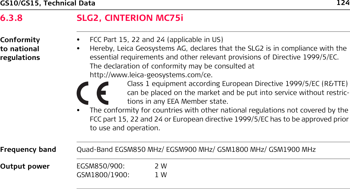
![GS10/GS15, Technical Data 125AntennaSpecific Absorption Rate (SAR)The product meets the limits for the maximum permissible exposure of the guide-lines and standards which are force in this respect. The product must be used with the recommended antenna. A separation distance of at least 20 centimetres should be kept between the antenna and the body of the user or nearby person within the intended application.Type Internal GAT 3 GAT 5Frequency band [MHz] 824 - 894 /890 - 960 /1710 - 1880 /1850 - 1990 /1920 - 2170890 - 960 /1710 - 1880 /1920 - 2170824 - 894 /1850 - 1990Type Internal Detachable λ/2 antennaDetachable λ/2 antennaConnector - TNC TNC](https://usermanual.wiki/Telit-Communications-S-p-A/CC864-DUAL.User-Manual/User-Guide-1250313-Page-125.png)
![126GS10/GS15, Technical Data6.3.9 SLC1 (US) CDMA Telit CC864-DUALConformity to national regulations• FCC Part 15, 22 and 24 (applicable in US)• The conformity for countries with other national regulations not covered by the FCC part 15, 22 and 24 has to be approved prior to use and operation.Frequency band Dual-Band CDMA800 MHz/CDMA1900 MHzOutput powerAntennaCDMA800: 0.27 WCDMA1900: 0.4 WType Internal GAT 5Frequency band [MHz] 824 - 894 /890 - 960 /1710 - 1880 /1850 - 1990 /1920 - 2170824 - 894 /1850 - 1990Type Internal Detachable λ/2 antennaConnector - TNC](https://usermanual.wiki/Telit-Communications-S-p-A/CC864-DUAL.User-Manual/User-Guide-1250313-Page-126.png)