Telit Communications S p A GG864 Gateway GSM/GPRS – 802.15.4 User Manual SWS Gateway Product Description rev1
Telit Communications S.p.A. Gateway GSM/GPRS – 802.15.4 SWS Gateway Product Description rev1
UserManual.wiki
>
Telit Communications S p A
>
GG864 User Manual
User product description
Navigation menu
Upload a User Manual
Namespaces
Wiki Guide
HTML
PDF
Info
Views
User Manual
Discussion / Help
Navigation

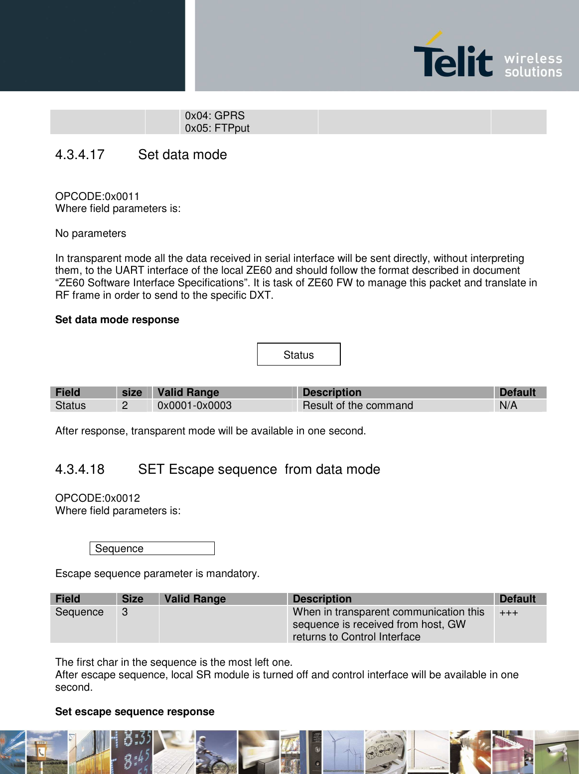
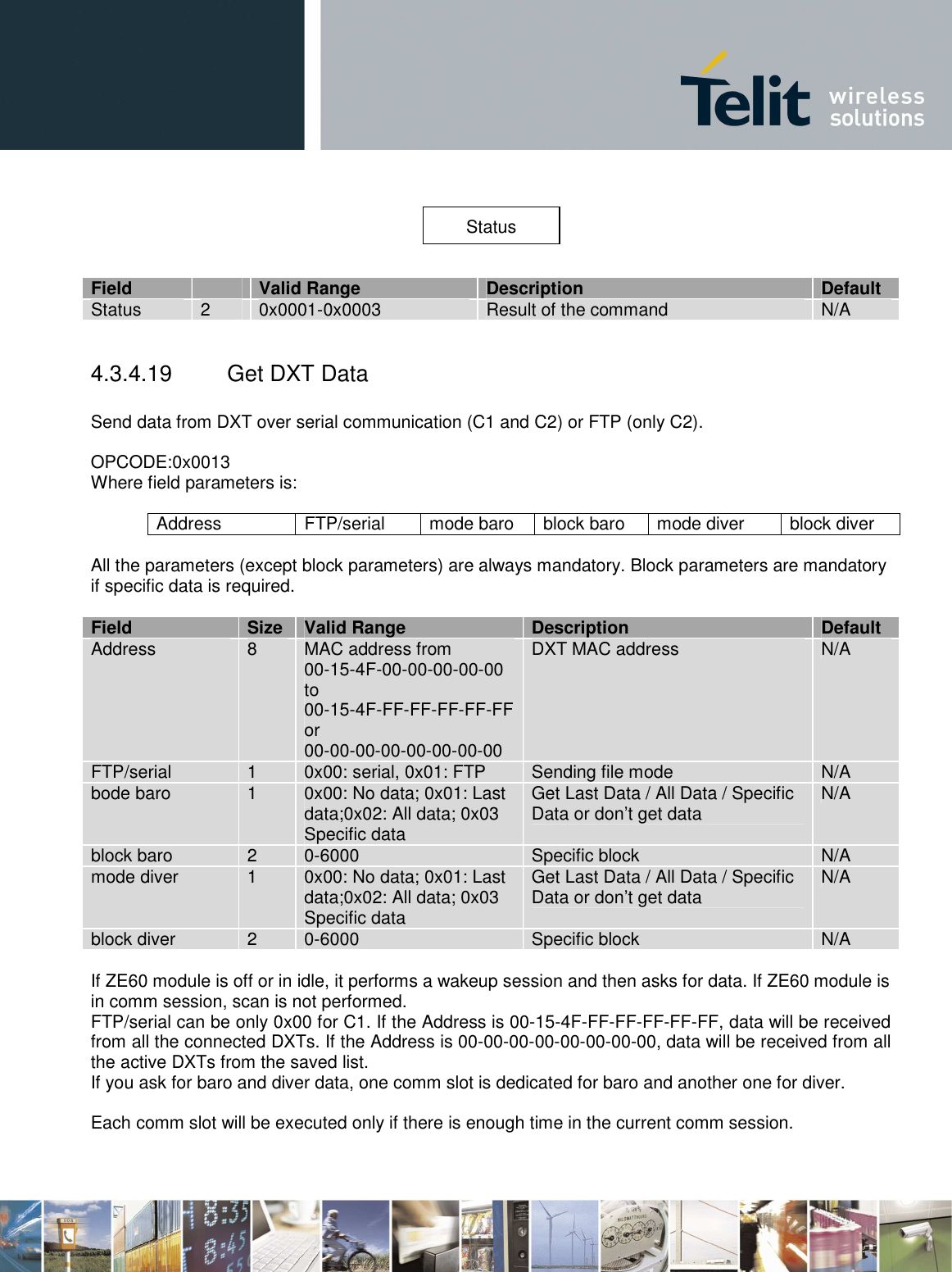
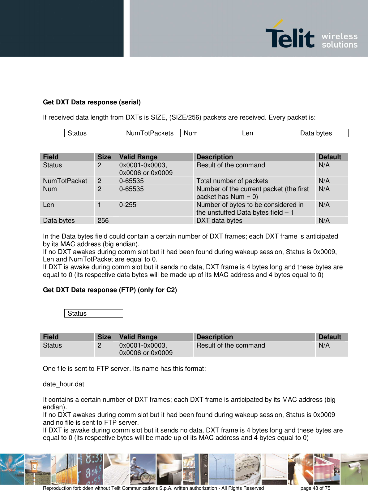
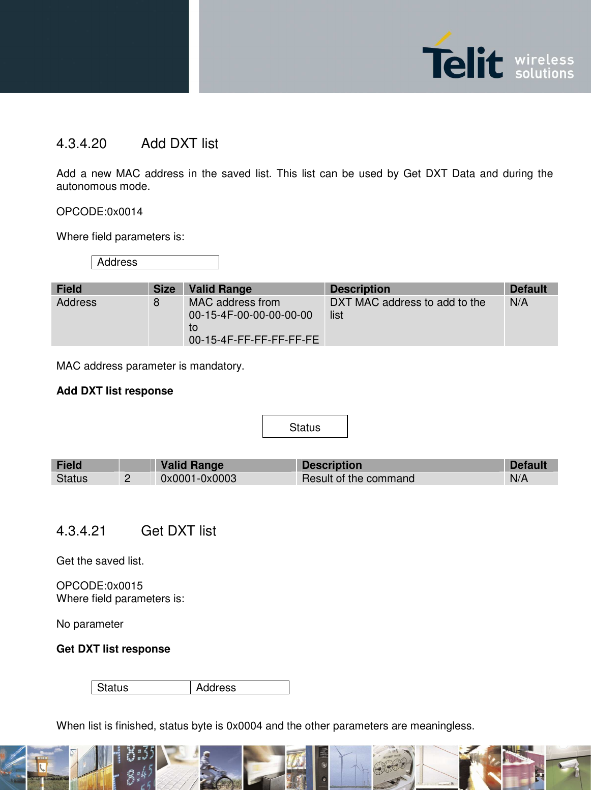
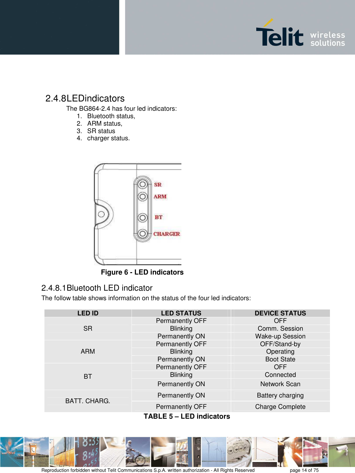
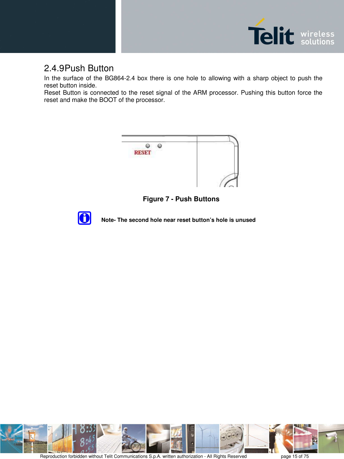
![1 Overview Scope of the document is detail technical specification, HW and SW for the 2 gateways BG864-2.4 and GG864-2.4. 1.1 Reference [1] Universal Gateway Specification v2B (Schlumberger Water Services- Divers Long range RF architecture) [2] Telit.ppt [3] ZE60 Software interface specification [4] cr 280912.pdf (meeting report 28/09/2009) [5] cr 151209.pdf( meeting report 15/12/2009) [6] protocol ideas.pdf 1.2 General System Architecture The proposed product satisfy the topology scenarios 1 and 2 as specified in [1] Figure 1 Topology Scenarios Telit provides the gateway in two different configurations](https://usermanual.wiki/Telit-Communications-S-p-A/GG864/User-Guide-1688937-Page-5.png)
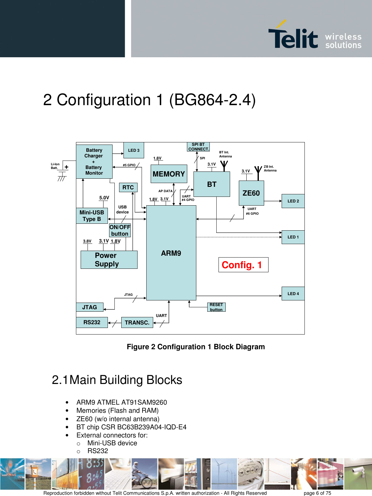
![Reproduction forbidden without Telit Communications S.p.A. written authorization - All Rights Reserved page 7 of 75 o Switch-slide Power-Supply • Internal antennas for: o BT o ZE60 • Rechargeable Li-Ion battery o continuos charging application will be allowedthe battery charging will be stopped when battery is completely charged. • Status Leds for: o BT o ZE60 o Charger o ARM • Box • Power supply: external 4.5÷5.5V from mini-USB connector or 3.4÷4.2V from Li-Ion battery • Reset button • Operational Temperature: [-20°C +60°C] • Storage Temperature: [-40°C- +85°C] 2.2 Main Building Blocks features • ARM9 ATMEL AT91SAM9260 Based on the ARM926EJ-S™ ARM® Thumb® Processor o 8-KByte Data Cache, 8-KByte Instruction Cache, Write Buffer o 200 MIPS at 180 MHz o Memory Management Unit o EmbeddedICE™, Debug Communication Channel Support o External Bus Interface (EBI) o USB 2.0 Full Speed (12 Mbits per second) Device Port o USB 2.0 Full Speed (12 Mbits per second) Host Single Port in the 208-lead PQFP o Ethernet MAC 10/100 Base T o Fully-featured System Controller, including o Reset Controller, Shutdown Controller o Four 32-bit Battery Backup Registers for a Total of 16 Bytes o Clock Generator and Power Management Controller o Advanced Interrupt Controller and Debug Unit o Periodic Interval Timer, Watchdog Timer and Real-time Timer o Reset Controller (RSTC) o Clock Generator (CKGR) o Selectable 32,768 Hz Low-power Oscillator or Internal Low Power RC Oscillator on o Battery Backup Power Supply, Providing a Permanent Slow Clock o Power Management Controller (PMC) • Memories (Flash and RAM) o COMBO NAND SDRAM 128 MB FLASH/64 MB RAM o Memory will be shared for: o Code o Data](https://usermanual.wiki/Telit-Communications-S-p-A/GG864/User-Guide-1688937-Page-7.png)
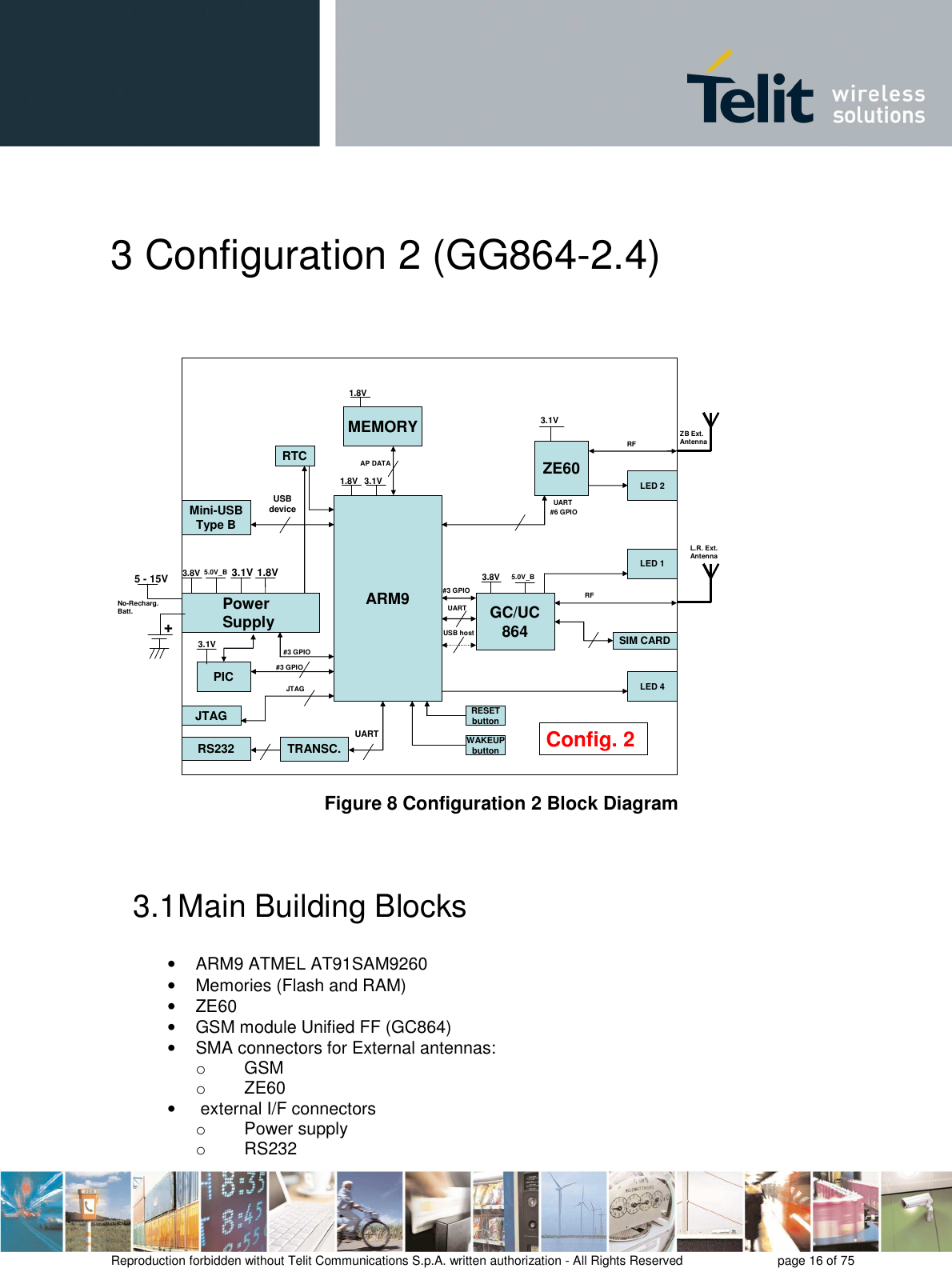
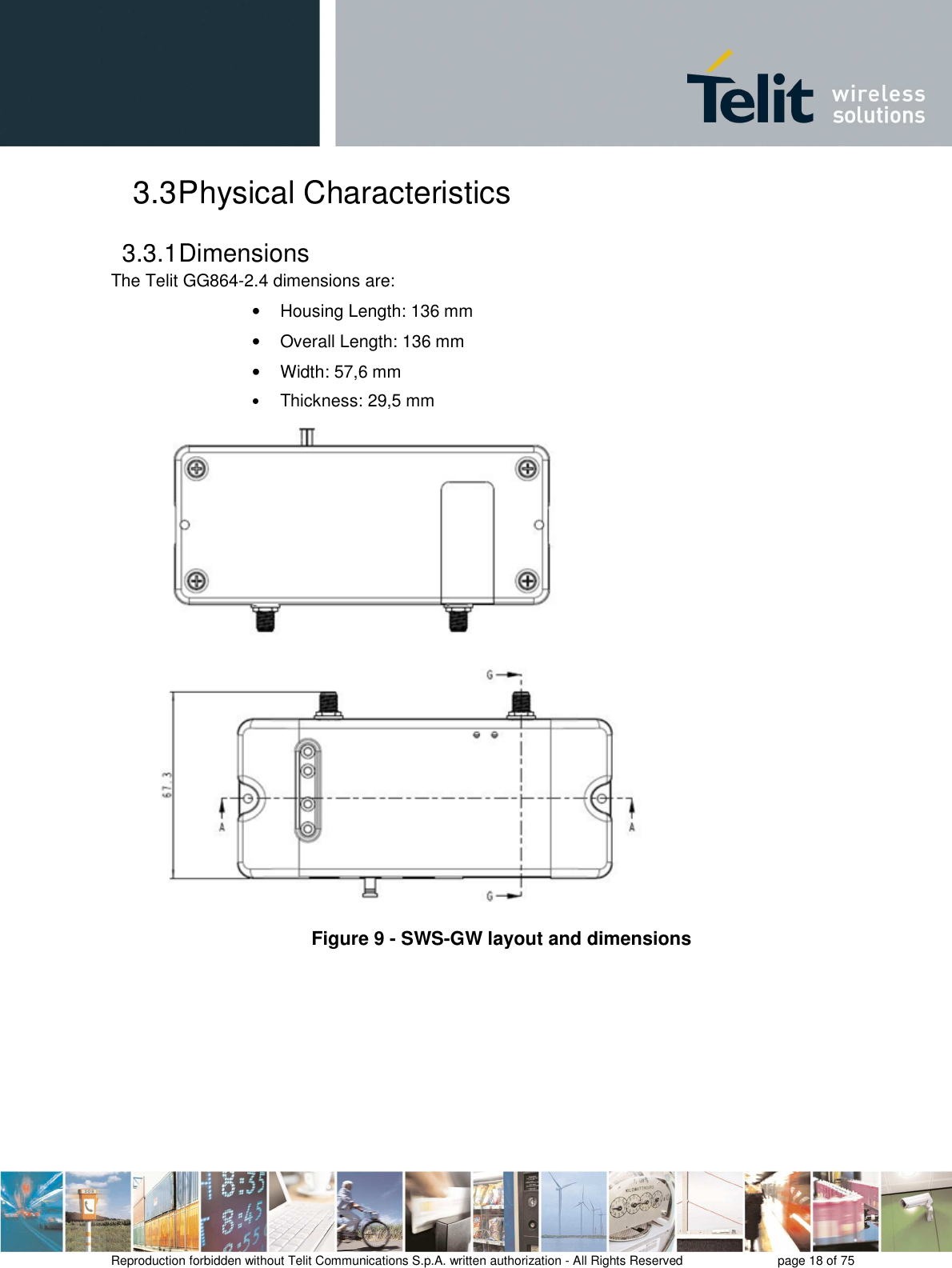
![Reproduction forbidden without Telit Communications S.p.A. written authorization - All Rights Reserved page 17 of 75 o SIM card holder o Mini-USB • Status leds for: o GSM o ZE60 o ARM • Box • Reset button and Wake-Up button • Power supply voltage 5-15V • Operational Temperature: [-20°C +70°C] • Storage Temperature: [-40°C- +80°C] 3.2 Main Building Blocks features • GC864 GSM module o Quad-band EGSM 850/900/1800/1900 MHz o Control via AT commands according to GSM 07.05, 07.07 and Telit enhancements o Serial Port multiplexer GSM 7.10 o SIMM access profile o TCP/IP stack access via AT commands o Supply voltage range: 3.22-4.5V DC o Dimensions: 30x36.2x3.2 mm o Weight: 6.1 grams o RoHS compliant o Extended temperature range - -40°C to 85°C (operational) - -40°C to 85°C (storage) o Sensitivity: - -107 dBm (typ.) @ 850/900 MHz - -106 dBm (typ.) @ 1800/1900 MHz o Power consumption (typ.) - Power off: <26 uA - Idle(registered, power saving): 2.6 mA - Dedicated mode: 200 mA - GPRS cl.10: 370 mA o Output power - Class 4 [2W] @ 850/900 MHz - Class 1 [1W] @ 1800/1900 MHz](https://usermanual.wiki/Telit-Communications-S-p-A/GG864/User-Guide-1688937-Page-17.png)

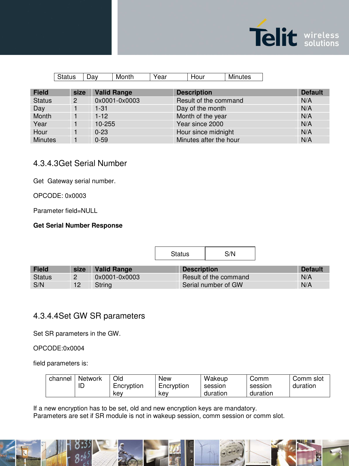
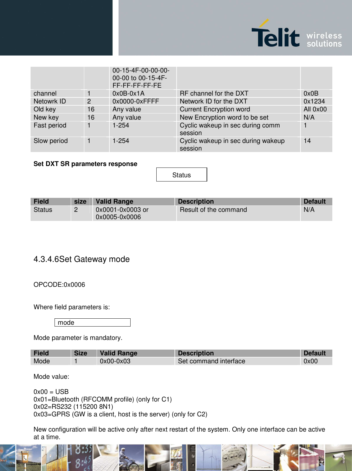
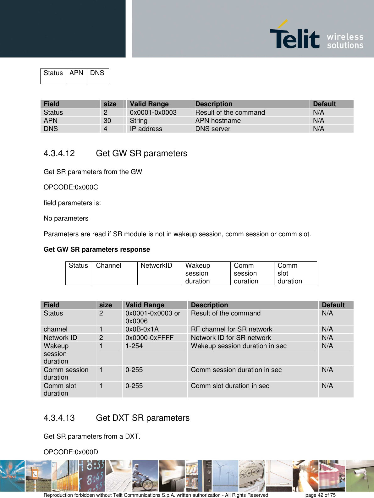
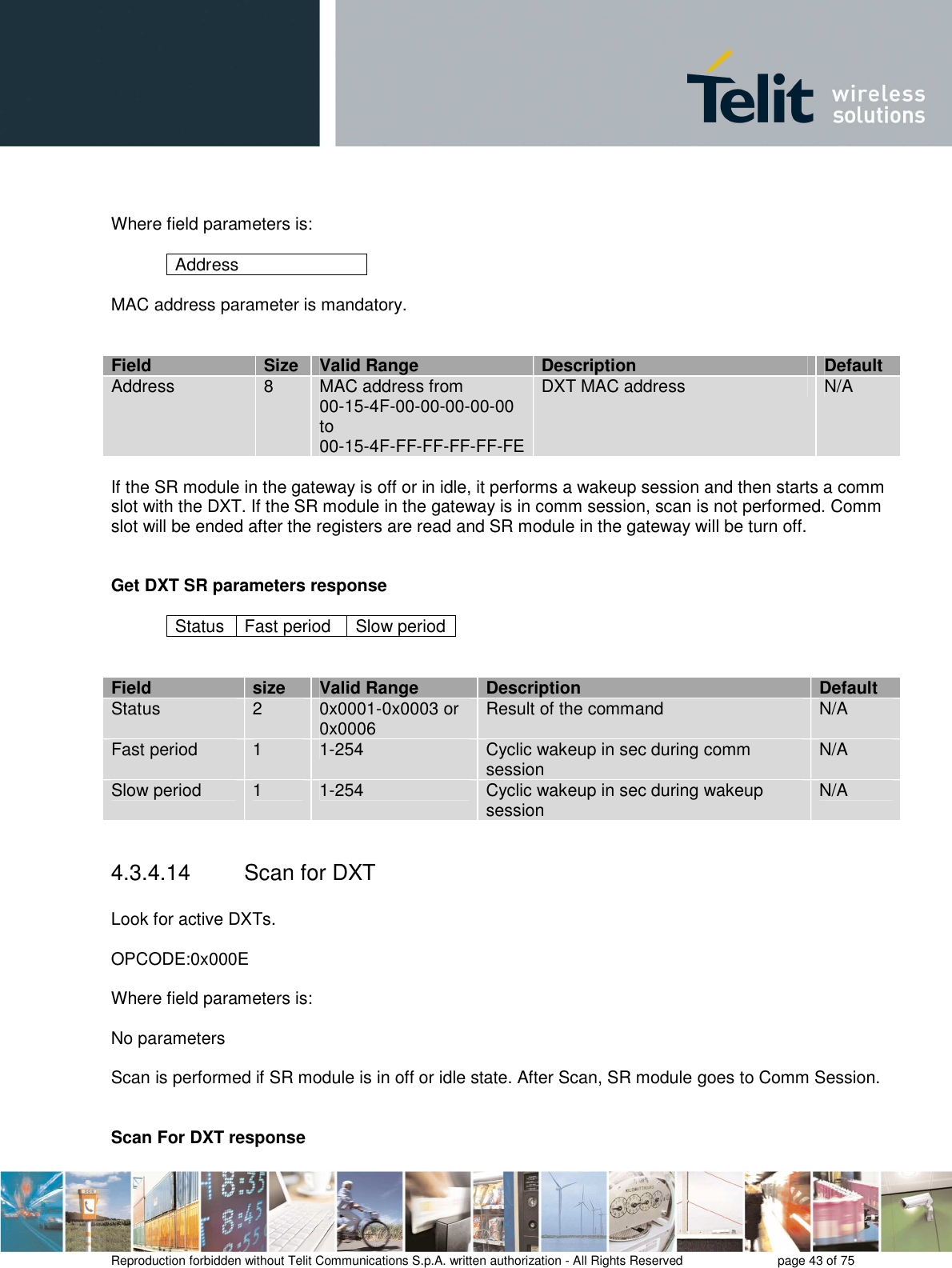
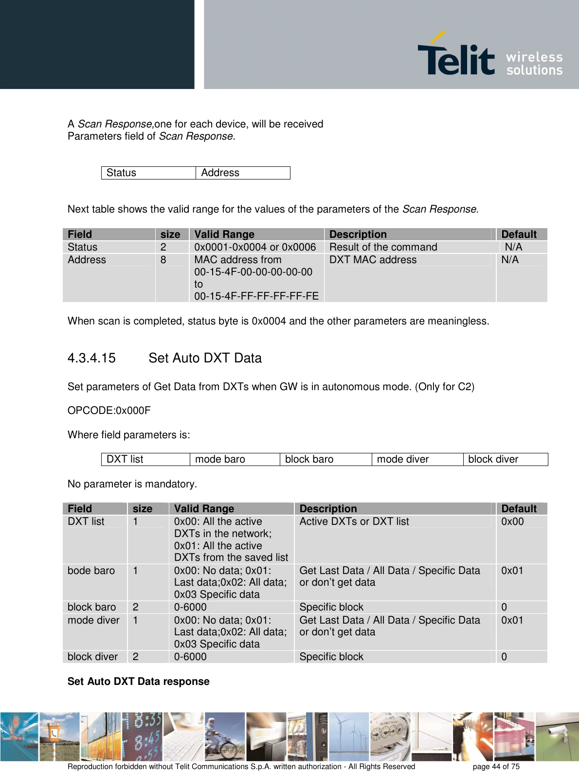
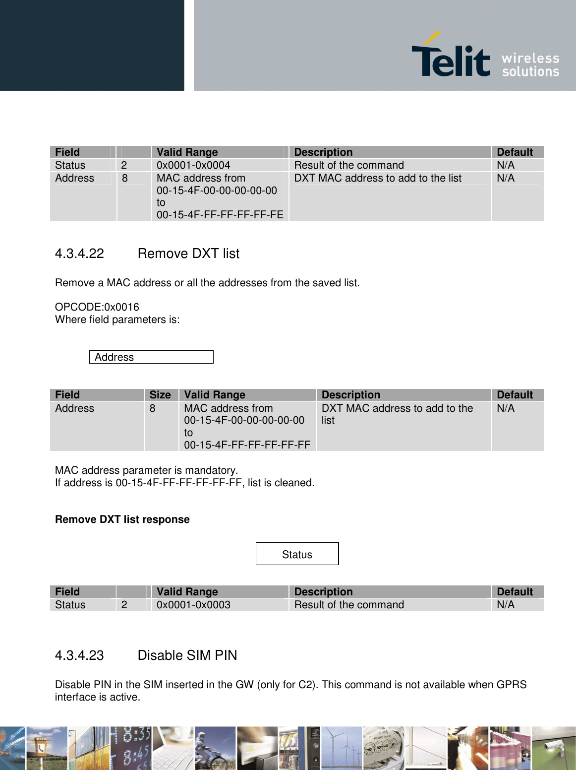
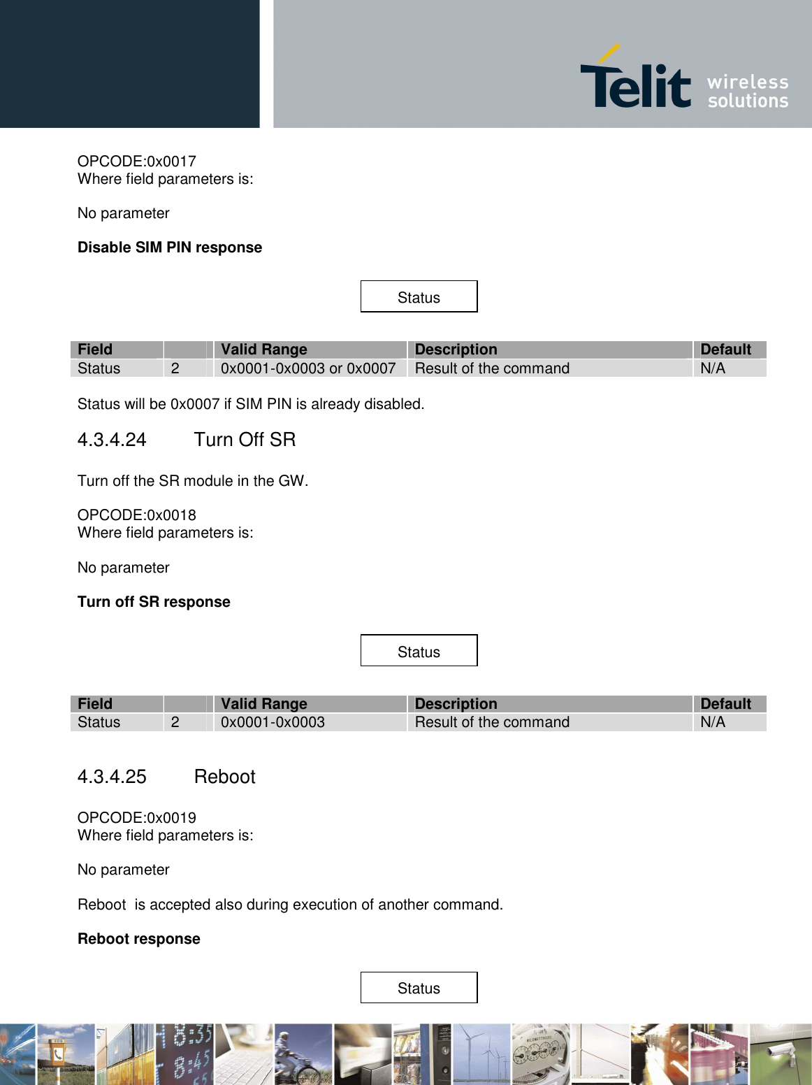
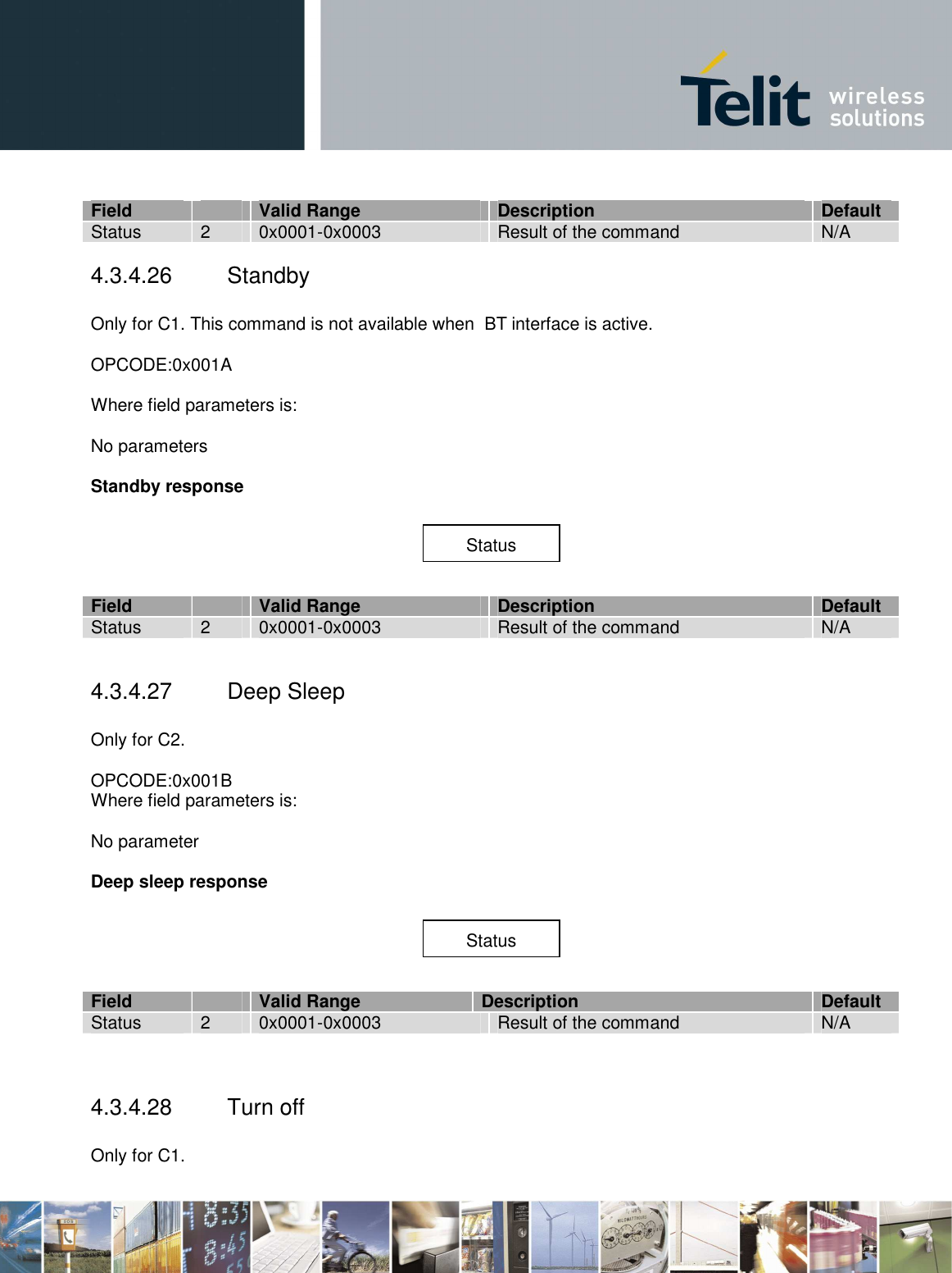
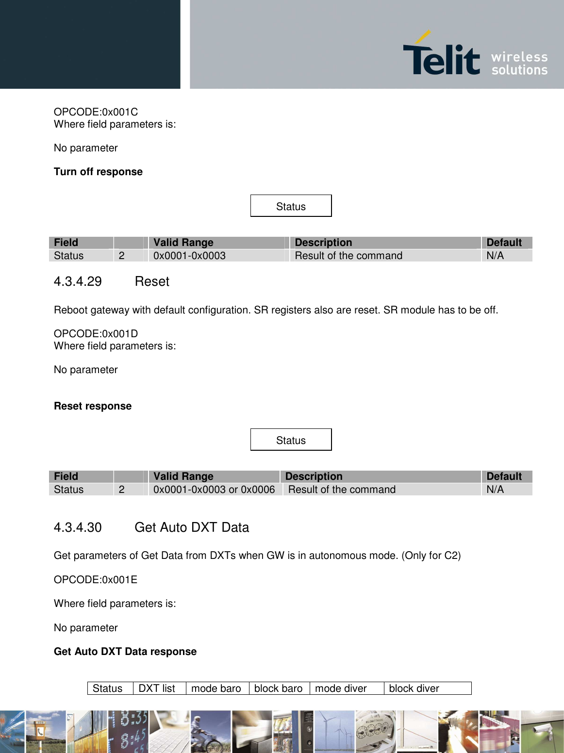
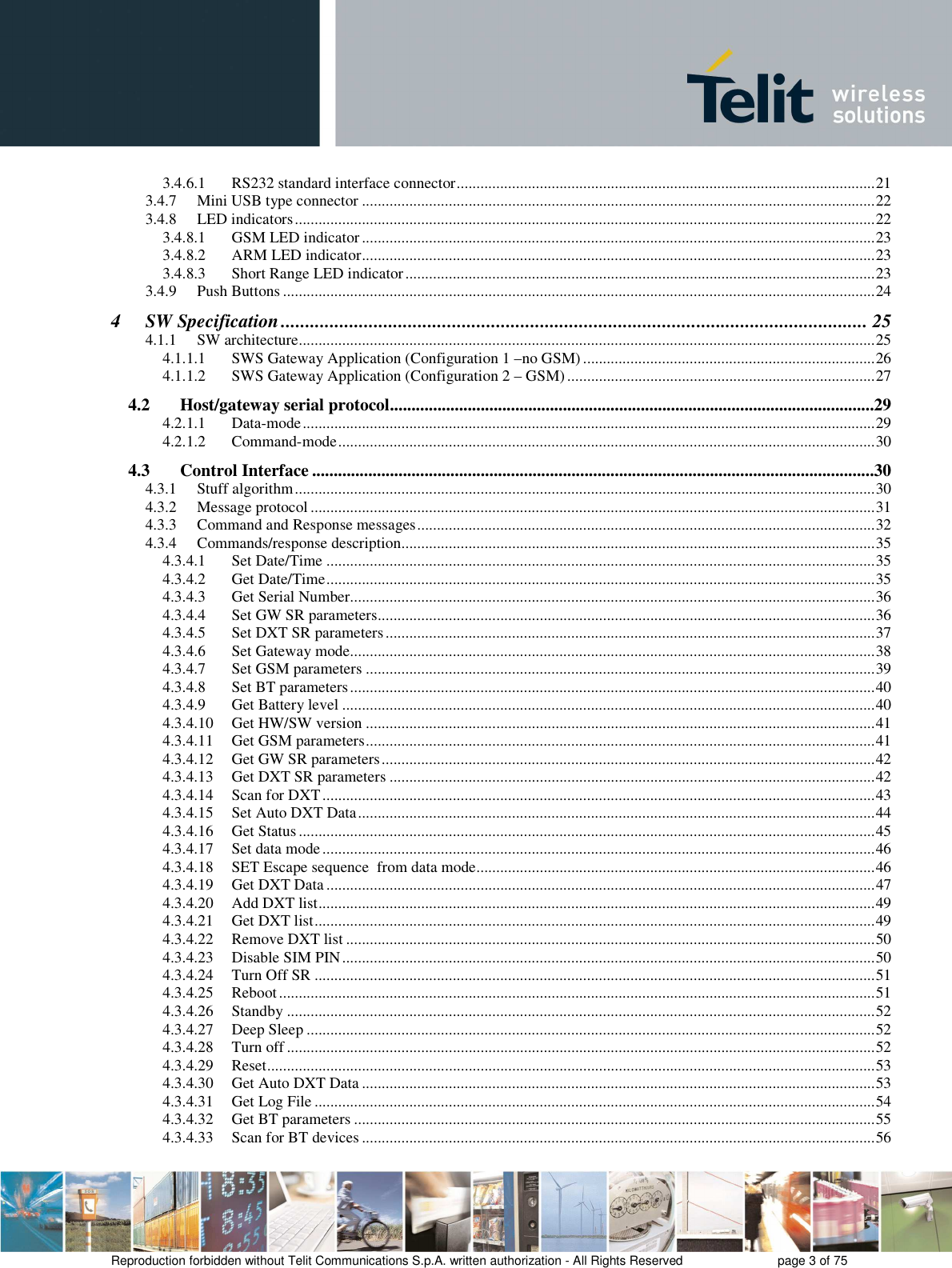
![Field size Valid Range Description Default channel 1 0x0B-0x1A RF channel for SR network 0x0B Network ID 2 0x0000-0xFFFF Network ID for the SR network 0x1234 Old key 16 Any value Current Encryption word All 0x00 New key 16 Any value New Encryption word to be set N/A Wakeup session duration 1 1-254 Wakeup session duration in sec 29 Comm session duration 1 0-255 Comm session duration in sec 120 Comm slot duration 1 0-255 Comm slot duration in sec 15 Set GW SR parameters response Field size Valid Range Description Default Status 2 0x0001-0x0003 or 0x0005-0x0006 Result of the command N/A 4.3.4.5 Set DXT SR parameters Set SR parameters in a DXT. OPCODE:0x0005 field parameters is: Address channel Network ID Old Encryption key New Encryption key Fast period Slow period MAC address parameter is always mandatory. If a new encryption has to be set, old and new encryption keys are mandatory. If the SR module in the gateway is off or in idle, it performs a wakeup session and then starts a comm slot with the DXT. If the SR module in the gateway is in comm session, scan is not performed. Comm slot will be ended after settings and SR module in the gateway will be turn off. NOTE: gateway will wait comm slot seconds for the dedicated wakeup response. If fast period will be greater than comm slot seconds, setting and getting registers or data from a DXT could fail. Generally, if slow period is greater than (wakeupSession/2 + 1), DXT could not wake up (see [3]). Field size Valid Range Description Default Address 8 MAC address from DXT MAC address N/A Status](https://usermanual.wiki/Telit-Communications-S-p-A/GG864/User-Guide-1688937-Page-37.png)