Telit Communications S p A LE70FH FHSS and DTS Module User Manual 1VV0301106 xE70 915 RF module User Guide r3
Telit Communications S.p.A. FHSS and DTS Module 1VV0301106 xE70 915 RF module User Guide r3
UserManual.wiki
>
Telit Communications S p A
>
LE70FH User Manual
User Manual
Navigation menu
Upload a User Manual
Namespaces
Wiki Guide
HTML
PDF
Info
Views
User Manual
Discussion / Help
Navigation
![xE70-915 RF Module User Guide 1VV0301106 rev.3 – 2015-03-04 Reproduction forbidden without written authorization from Telit Communications S.p.A. - All Rights Reserved. Page 7 of 34 1. Introduction 1.1. Scope Scope of this document is to present the features and the application of the Telit xE70-915 radio modules. 1.2. xE70-915 Product Description The xE70-915 module is a multi-channel radio board, delivering up to 500mW in Frequency Hopping technology. It is compliant with the FCC Code of Federal Regulations [1] in the 915 MHz ISM unlicensed frequency band. It is delivered with preloaded protocol stack: “x” Product name Stack functionality L LE70-915 FH Star Network xE70-915 is pin-to-pin compatible with LE, NE and ME modules working at different frequencies, in particular xE50-868 and xE70-868. xE70-915 is also pin-to-pin compatible with Telit ZE Family (ZigBee 2007 and ZigBee PRO stack). 1.3. Audience This document is intended for developers using Telit xE70-915 radio modules. 1.4. Contact Information, Support For general contact, technical support, to report documentation errors and to order manuals, contact Telit Technical Support Center (TTSC) at: TS-SRD@telit.com TS-NORTHAMERICA@telit.com TS-LATINAMERICA@telit.com TS-APAC@telit.com Alternatively, use: http://www.telit.com/en/products/technical-support-center/contact.php For detailed information about where you can buy the Telit modules or for recommendations on accessories and components visit: http://www.telit.com](https://usermanual.wiki/Telit-Communications-S-p-A/LE70FH/User-Guide-2670168-Page-7.png)
![xE70-915 RF Module User Guide 1VV0301106 rev.3 – 2015-03-04 Reproduction forbidden without written authorization from Telit Communications S.p.A. - All Rights Reserved. Page 8 of 34 To register for product news and announcements or for product questions contact Telit Technical Support Center (TTSC). Our aim is to make this guide as helpful as possible. Keep us informed of your comments and suggestions for improvements. Telit appreciates feedback from the users of our information. 1.5. Text Conventions Danger – This information MUST be followed or catastrophic equipment failure or bodily injury may occur. Caution or Warning – Alerts the user to important points about integrating the module, if these points are not followed, the module and end user equipment may fail or malfunction. Tip or Information – Provides advice and suggestions that may be useful when integrating the module. All dates are in ISO 8601 format, i.e. YYYY-MM-DD. 1.6. Related Documents • [1] Code of Federal Regulations, Title 47, Part 15 • [2] Frequency Hopping Star Network Protocol Stack User Guide, 1vv0301059 • [3] SR Tool User Guide, 1vv0300899](https://usermanual.wiki/Telit-Communications-S-p-A/LE70FH/User-Guide-2670168-Page-8.png)
![xE70-915 RF Module User Guide 1VV0301106 rev.3 – 2015-03-04 Reproduction forbidden without written authorization from Telit Communications S.p.A. - All Rights Reserved. Page 9 of 34 2. Regulatory Conformance Information 2.1. Operational Frequency Bands The module radio transmitter operations must be compliant with some regulatory requirements in terms of frequency bands and emitted power, as detailed below. 2.1.1. 915 MHz Band Requirements The FCC part 15.247 regulates the frequency hopping RF devices, and gives the following requirements: Frequency Band Channel spacing Maximum radiated power Hopping cycle 902-928 MHz 25< “20dB BW” < 250kHz 1W <0.4s each 20s<0.4s each 20s, 50 hop. Freq min 250 < “20dB BW” < 500kHz 250mW <0.4s each 10s, 25 hop. Freq. min The main requirements of the FCC regulation are given in [1]. The xE70-915 module operates in the ISM band. This band is free to use but the module and the user must respect some limitations. Most of these restrictions are integrated in the conception of the module. 2.2. Other Regulatory Requirements The module complies with the European Directive 2002/95/EC concerning the Restrictive Usage of Hazardous Substances (RoHS).](https://usermanual.wiki/Telit-Communications-S-p-A/LE70FH/User-Guide-2670168-Page-9.png)
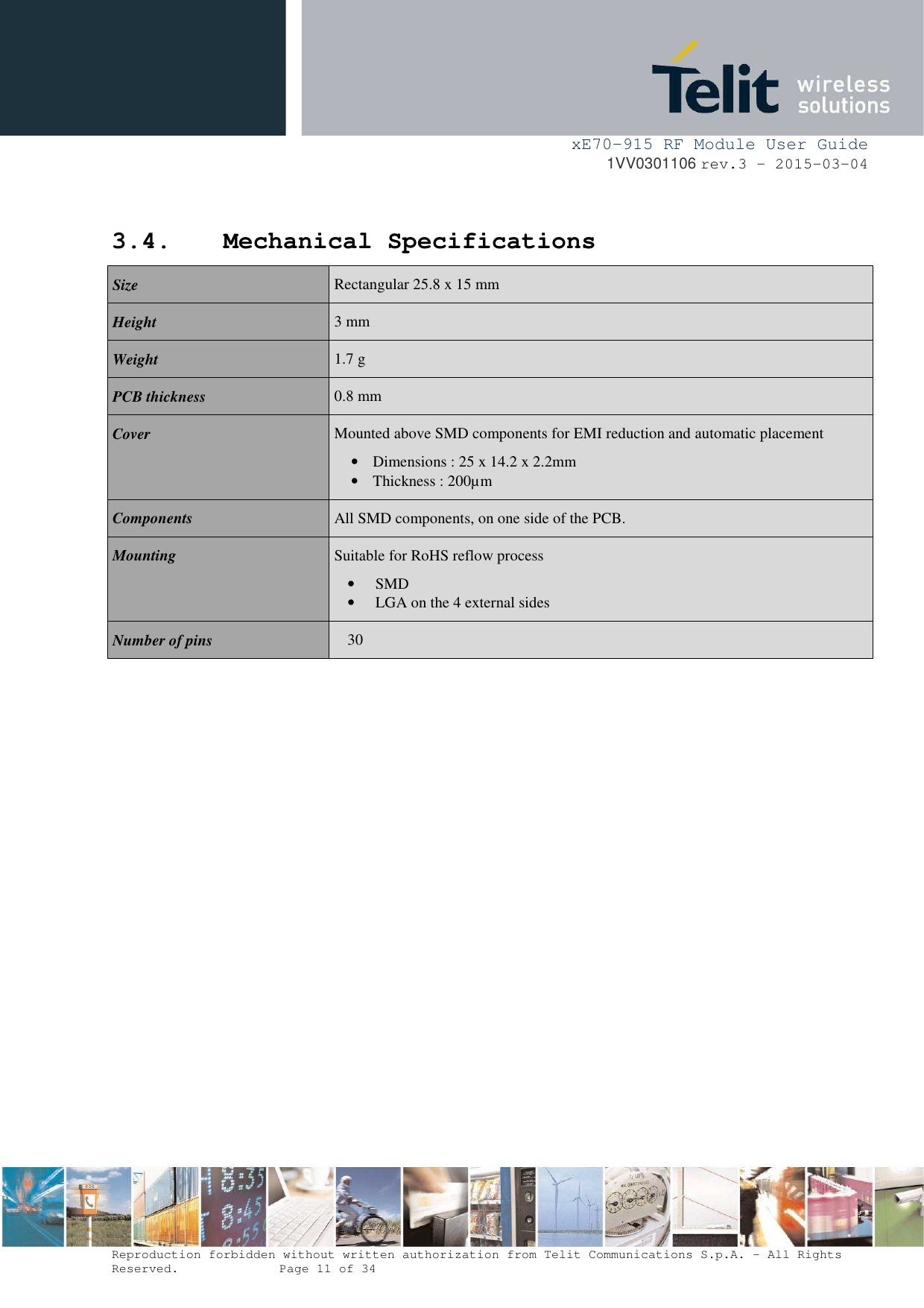
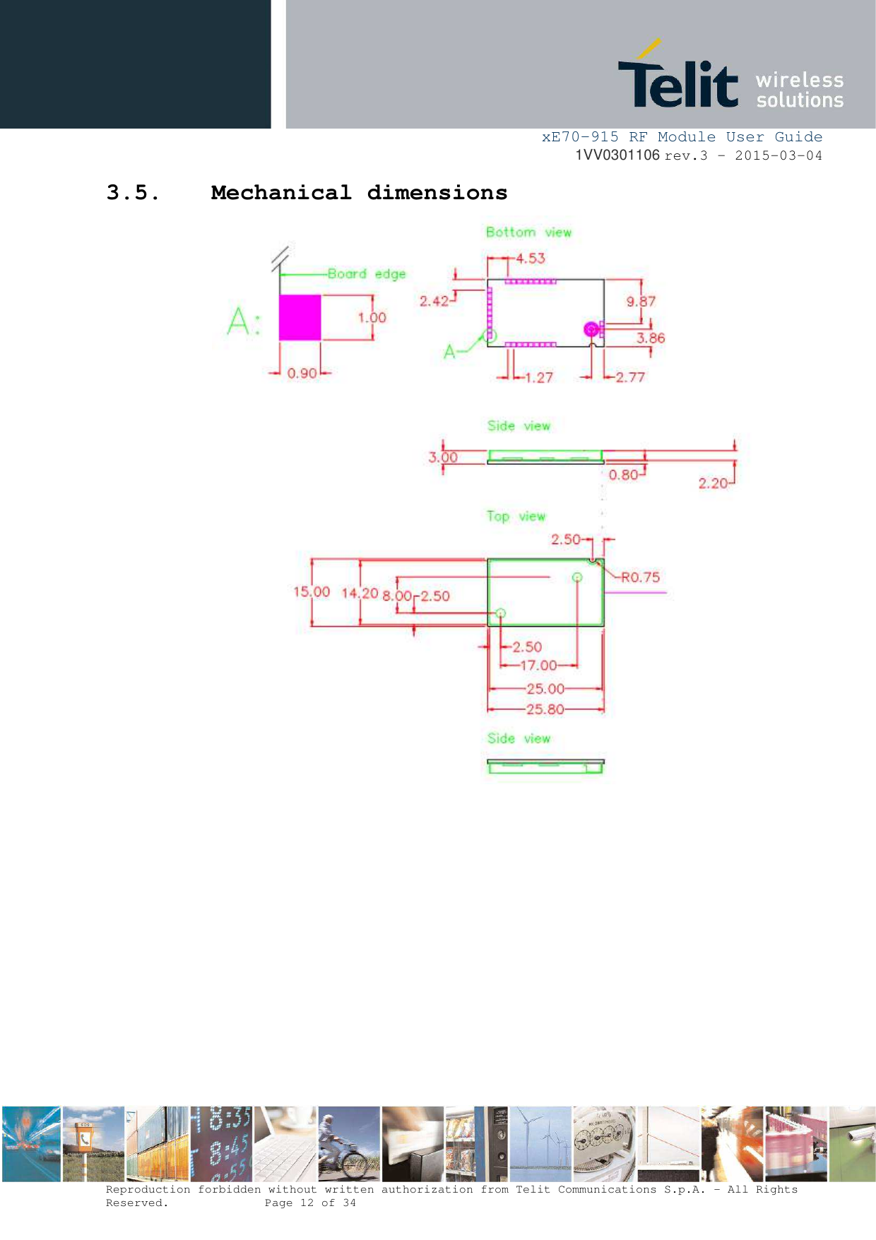
![xE70-915 RF Module User Guide 1VV0301106 rev.3 – 2015-03-04 Reproduction forbidden without written authorization from Telit Communications S.p.A. - All Rights Reserved. Page 10 of 34 3. General Features 3.1. Main Functionalities The xE70-915 module is a complete solution from serial interface to RF interface. The xE70-915 module has a digital part and a RF part. The radio link is a Half Duplex bi-directional link. The digital part has the following functionalities: • Communication interface • I/O management • Micro controller with embedded Telit Software Stack The RF part has the following functionalities: • Frequency synthesis • Front-end • Low noise reception • Power amplification • Packet handling 3.2. Software The xE70-915 module is provided pre-flashed with Telit in-house stack. Please refer to Protocol Stack User Guides [2] for detailed information. 3.3. Temperature Requirements Minimum Typical Maximum Unit Operating Temperature - 40 25 + 85 °C Relative humidity @ 25°C 20 75 % Storage Temperature - 40 25 + 85 °C](https://usermanual.wiki/Telit-Communications-S-p-A/LE70FH/User-Guide-2670168-Page-10.png)
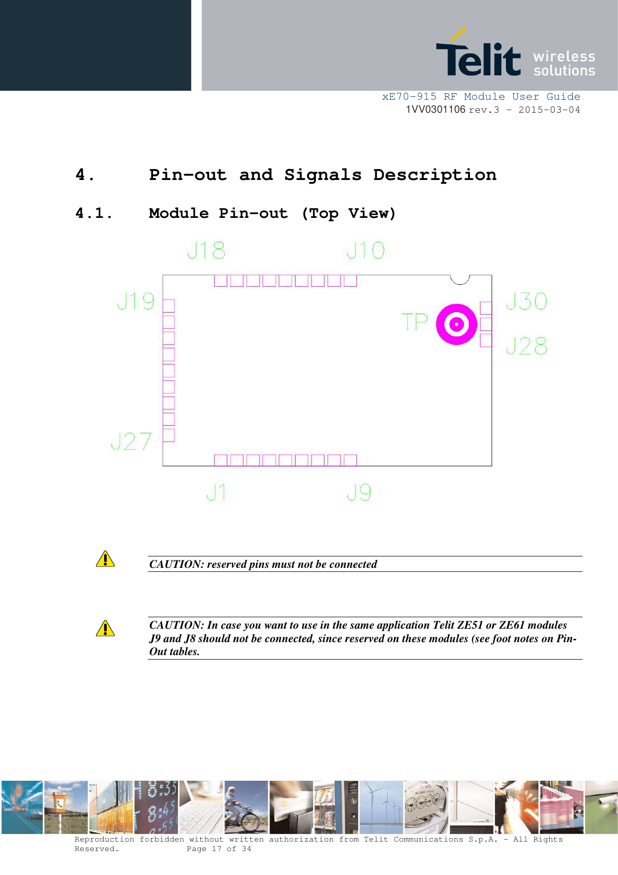
![xE70-915 RF Module User Guide 1VV0301106 rev.3 – 2015-03-04 Reproduction forbidden without written authorization from Telit Communications S.p.A. - All Rights Reserved. Page 18 of 34 4.2. Module Pin-out Table Pin Pin name Pin type Signal level Function J30 GND Gnd RF Ground connection for external antenna J29 Ext_Antenna RF RF I/O connection to external antenna J28 GND Gnd RF Ground connection for external antenna J27 GND Gnd Ground J26 GND Gnd Ground J25 VDD Power Digital and Radio part power supply pin J24 CTS I TTL Clear To Send J23 RESET I TTL µC reset ( Active low with internal pull-up ) J22 RTS O TTL Request To Send J21 RXD I TTL RxD UART – Serial Data Reception J20 GND Gnd Ground J19 TXD O TTL TxD UART – Serial Data Transmission J18 STAND_BY I TTL Standby (Active high with internal pull-down: when set to 1 the module is put in stand-by) J17 GND Gnd Ground J16 PROG I TTL Signal for serial µC flashing (Active high with internal pull-down) J15 GND Gnd Ground J14 PDI_DATA I/O TTL Program and Debug Interface DATA J13 GND Gnd Ground J12 GND Gnd Ground J11 GND Gnd Ground J10 PDI_CLK I TTL Program and Debug Interface CLOCK J9 IO91 I/O TTL Digital I/O N°9 with interrupt Status TX/RX O TTL See reference document [2] Frequency Hopping Star Network Protocol Stack User Guide J8 IO8_AD_DA2 I/O analog A to D and D to A I/O N°8 with interrupt (Logic I/O capability) ACK TX O TTL See reference document [2] Frequency Hopping Star Network Protocol Stack User Guide J7 IO7_A I/O analog Analog Input N°7 (Logic I/O capability) J6 IO6_A I/O analog Analog Input N°6 (Logic I/O capability) J5 IO5_A I/O analog Analog Input N°5 (Logic I/O capability) J4 IO4_A I/O analog Analog Input N°4 (Logic I/O capability) J3 IO3_A I/O analog Analog Input N°3 (Logic I/O capability) 1, 2 In case you want to use in the same application Telit ZE51 or ZE61 modules J9 and J8 should not be connected, since reserved on these modules.](https://usermanual.wiki/Telit-Communications-S-p-A/LE70FH/User-Guide-2670168-Page-18.png)
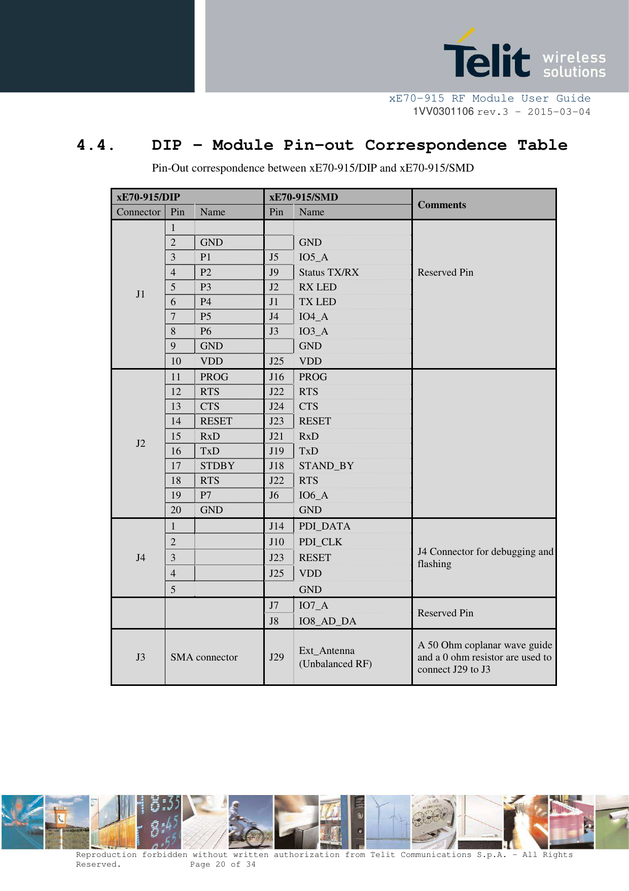
![xE70-915 RF Module User Guide 1VV0301106 rev.3 – 2015-03-04 Reproduction forbidden without written authorization from Telit Communications S.p.A. - All Rights Reserved. Page 19 of 34 J2 IO2_P I/O TTL Logic I/O N°2 with interrupt RX LED O TTL See reference document [2] Frequency Hopping Star Network Protocol Stack User Guide J1 IO1_P I/O TTL Logic I/O N°1 with interrupt TX LED O TTL See reference document [2] Frequency Hopping Star Network Protocol Stack User Guide 4.3. Pin-out of the Module DIP](https://usermanual.wiki/Telit-Communications-S-p-A/LE70FH/User-Guide-2670168-Page-19.png)
![xE70-915 RF Module User Guide 1VV0301106 rev.3 – 2015-03-04 Reproduction forbidden without written authorization from Telit Communications S.p.A. - All Rights Reserved. Page 21 of 34 4.5. Signals Description Signals Description Reset External hardware reset of the radio module. Active on low state. TXD, RXD Serial link signals, format NRZ/TTL: TXD is for outgoing data. RXD is for incoming data. The ‘1’ is represented by a high state. CTS Incoming signal. Indicates whether the module can send serial data to user (Active, on low state) or not (inactive, on high state). RTS Outgoing signal. Indicates whether the user can transmit serial data (active, on low state) or not (inactive, on high state). IO I/O, configurable as input or as output. See reference document [2] for LE70-915. STANDBY Input signal which indicates to the module to switch to pre-selected low-power mode. See reference document [2] for LE70-915 TX LED Output signal set to VCC during radio transmission and set to GND the rest of the time RX LED Output signal set to VCC as soon as a radio frame is detected with correct synchronization word. The signal returns to GND as soon as the frame reception is finished ACK TX In Addressed Secured mode, this signal rises to VCC when an ACK hasn’t been received after frame transmission and repetition. This is the hardware version of “ERROR” serial message. It stays at VCC until next success addressed secured transmission STATUS TX/RX Output signal which indicates the status of the serial port. When serial port is transmitting, Status RX/TX signal goes VCC until the end of serial transmission. The signal stays to GND the rest of the time](https://usermanual.wiki/Telit-Communications-S-p-A/LE70FH/User-Guide-2670168-Page-21.png)