Telit Communications S p A LN931NAG Data Card User Manual LN931 NAG HW guide
Telit Communications S.p.A. Data Card LN931 NAG HW guide
User Manual rev2.pdf
- 1 -
LN931-NAG
Hardware Specification

- 2 -
CONTENTS
1.
GENERAL DESCRIPTION....................................................................4
1.1
SYSTEM MAIN FEATURE ....................................................................5
1.2
SYSTEM BLOCK DIAGRAM ................................................................8
1.3
PIN DEFINITION .....................................................................................9
1.4
PLATFORM CONNECTION DESIGN ............................................... 14
2.
HARDWARE FEATURES ................................................................... 22
2.1 MOBILE DATA MODEM ............................................................................ 22
2.2 RF TRANSCEIVER ..................................................................................... 23
2.3 POWER MANAGEMENT IC ...................................................................... 23
2.4 ANTENNA DESIGN .................................................................................... 24
3.
MECHANICAL SPECIFICATIONS .................................................... 27
3.1 OVERVIEW .................................................................................................. 27
3.2 MECHANICAL CONSTRAINTS ................................................................ 27
3.3 M.2 CARD ASSEMBLY .............................................................................. 28
3.4 CONNECTOR ASSEMBLY ....................................................................... 29
4.
ELECTRICAL SPECIFICATIONS ...................................................... 30
4.1 RECOMMENDED OPERATING CONDITIONS ...................................... 30
4.2 POWER CONSUMPTION .......................................................................... 30
5.
RF PERFORMANCE SPECIFICATIONS .......................................... 31
- 3 -
5.1 RF MAXIMUM TX POWER SPECIFICATIONS ...................................... 31
5.2 RF MIN. RX SENSITIVITY SPECIFICATIONS ........................................ 32
6.
SOFTWARE REQUIREMENTS.......................................................... 33

4
1. General Description
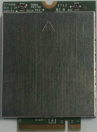
T77H468 is designed to enable wireless data connectivity for notebook computer or any
other device compatible with the PCI Express M.2 Specification 3042 type slot. T77H468 is
the data card solution that delivers wireless wide-area network (WWAN) connectivity for the
LTE, UMTS (HSDPA/HSUPA/HSPA+/DC-HSPA+), CDMA 1xRTT/CDMA EV-DOrA/ CDMA
EVDO-rB, GSM/GPRS/EDGE and GPS/Glonass protocols in one hardware configuration.
WTR1605L SKU NA-1-S3
G C W L
QUAD BAND BC 0,1 Band 1,2,4, 5,8 Band 2,4,5,13,17,25
TX_LB1 17
TX_LB2 850/900
TX_LB3 13
TX_LB4 0 5,8 5, 8r
TX_MB1 4 4
TX_MB2 1800/1900
TX_MB3 1 1,2 1r, 2,25
TX_MB4
TX_HB
PRX_LB1 13,17
PRX_LB2 850/900 8
PRX_LB3 0 5 5
PRX_MB1 1800/1900
PRX_MB2 1 2 2
PRX_MB3 1
PRX_HB 4 4
DRX_LB1 0 5,8 5
DRX_LB2 17
DRX_LB3 13
DRX_MB 1 2 2,25
DRX_HB 1,4 4

5
1.1 System Main Feature
Feature Description
Physical PCI express M.2 module, size 3042, 75Pin golden finger
Electrical Single VCC supply (3.3V+/-5% follow M.2 standard)
Dimension Dimensions (L × W × H): 42 mm × 30 mm × 2.3 mm,
maximum height=2.38mm (add PCB tolerance=0.08mm)
Shielding design Shield case on board design, no additional shielding
requirement
Weight
Approximately
6.2g
USIM Off-board USIM connector supported
Operating Bands
WCDMA/HSDPA/HSUPA/HSPA+ operating bands:
Band 1: 1920 to 1980 MHz (UL), 2110 to 2170 MHz (DL)
Band 2: 1850 to 1910 MHz (UL), 1930 to 1990 MHz (DL)
Band 4: 1710 to 1755 MHz (UL), 2110 to 2155 MHz (DL)
Band 5: 824 to 849 MHz (UL), 869 to 894 MHz (DL)
Band 8: 880 to 915 MHz (UL), 925 to 960 MHz (DL)
GSM operating bands:
GSM850: 824 to 849 MHz (UL), 869 to 894 MHz (DL)
E-GSM900: 880 to 915 MHz (UL), 925 to 960 MHz (DL)
DCS1800: 1710 to 1785 MHz (UL), 1805 to 1880 MHz (DL)
PCS1900: 1850 to 1910 MHz (UL), 1930 to 1990 MHz (DL)
LTE FDD operating bands:
Band 2: 1850 to 1910 MHz (UL), 1930 to 1990 MHz (DL)
Band 4: 1710 to 1755 MHz (UL), 2110 to 2155 MHz (DL)
Band 5: 824 to 849 MHz (UL), 869 to 894 MHz (DL)
Band 13: 777 to 787 MHz (UL), 746 to 756 MHz (DL)
Band 17: 704 to 716 MHz (UL), 734 to 746 MHz (DL)
Band 25: 1850 to 1915 MHz (UL), 1930 to 1995 MHz (DL)
CDMA 1X/CDMA EV-DOrB operating bands:
BC0: 824 to 849 MHz (UL), 869 to 894 MHz (DL)
BC1: 1850 to 1910 MHz (UL), 1930 to 1990 MHz (DL)
Diversity/2nd Rx
All
WCDMA/HSDPA/HSUPA/HSPA+ operating bands
All CDMA 1X/CDMA EVDO
operating bands
All
LTE operating bands
GNSS GPS: L1 (1575.42MHz)
GLONASS: L1 (1602MHz)
USIM Voltage Support 1.8V and 2.85V, and auto detects follow SIM card type
Antenna connectors
MAIN and AUX(supports Diversity and GPS simultaneously)

6
Throughput
GPRS: DL 85.6 kbps /UL 85.6 kbps
EDGE: DL 236.8 kbps/UL 236.8 kbps
WCDMA CS: DL 64 kbps /UL 64 kbps
WCDMA PS: DL 384 kbps /UL 384 kbps
HSPA+: DL 21.6 Mbps /UL 5.76 Mbps
DC-HSPA+ :DL 42 Mbps/UL 5.76 Mbps
CDMA 1x: DL 153.6 kbps/UL 153.6 kbps
EVDO Rev.A: DL 3.1 Mbps /UL 1.8 Mbps
EVDO Rev.B: DL 14.7 Mbps/UL 5.4 Mbps
LTE FDD:DL:100 Mbps/UL 50 Mbps @20M BW cat3
LTE air interface
LTE R9, Cat3, 20MHz BW (FDD: up to 100 Mbps downlink, 50 Mbps uplink)
FDD: up to 100 Mbps downlink, 50 Mbps uplink
1.4 to 20 MHz RF bandwidth
1X2 MISO (1Tx and 2Rx for two downlinks simultaneously)
IPv6, QoS
WCDMA/HSPA air interface
R99:
All modes and data rates for WCDMA FDD
R5 HSDPA
PS data speeds up to 7.2 Mbps on the downlink
R6 HSUPA
E-DCH data rates of up to 5.76 Mbps for 2 ms TTI (UE category 6) uplink
R7 HSPA+
Downlink 64 QAM; up to 21 Mbps
1X2 MISO (1Tx and 2Rx for two downlinks simultaneously)
2Rx with 16 QAM; up to 28 Mbps
Uplink 16 QAM; up to 5.76 Mbps
R8 DC-HSPA+
Downlink dual carrier with 64 QAM; up to 42 Mbps
CDMA air interface
1xRTT
153.6 kbps forward link, 153.6 kbps reverse link
1xEV-DOr0
High-speed peak data rates – 2.4 Mbps forward link; 153 kbps reverse link
1xEV-DOrA
High-speed peak data rates – 3.1 Mbps forward link; 1.8 Mbps reverse link
1xEV-DOrB
7
High-speed peak data rates – 14.7 Mbps forward link; 5.4 Mbps reverse link
GSM / GPRS / EDGE air interface
R99
Circuit-switched data: 9.6 k; 14.4 k
GPRS
Packet-switched data:
DTM (simple class A) operation
Multi-slot class 12 data services
CS schemes – CS1, CS2, CS3, and CS4
GEA1, GEA2, and GEA3 ciphering
Maximum of four Rx timeslots per frame
EDGE
E2 power class for 8 PSK
DTM (simple class A), multislot class 12
Downlink coding schemes – CS 1-4, MCS 1-9
Uplink coding schemes – CS 1-4, MCS 1-9
BEP reporting
SRB loopback and test mode B
8-bit and 11-bit RACH
PBCCH support
One-phase/two-phase access procedures
Link adaptation and IR
NACC, extended UL TBF
GNSS
GPS
Standalone, MS-A, MS-B, and XTRA GPS
Glonass
GLONASS standalone mode
GLONASS capability increases the number of satellites available to the positioning
engine, resulting in an expanded area of coverage over traditional GPS receivers
8
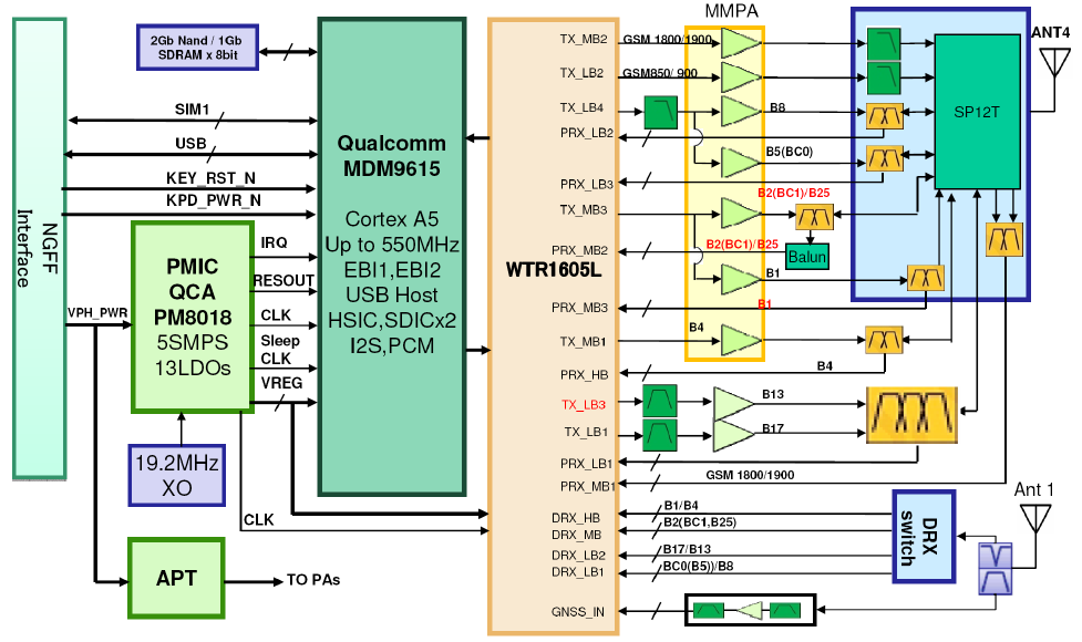
1.2 System Block Diagram
Figure 1-1 System block diagram
Chipsets: MDM9615+WTR1605L+PM8018
9
1.3 Pin definition
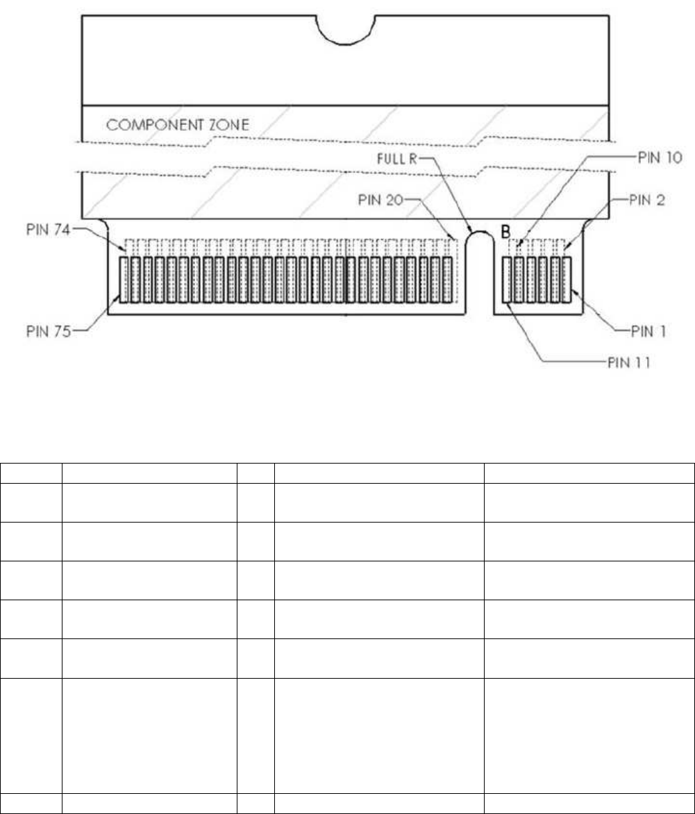
1.3.1 Golden finger Pin sequence
Figure 1-2 shows the sequence of pins on the 75-pin signal interface of M.2 3042.
1.3.2 Pin definition
Table 1-1 M.2 Pin definition
No. M.2 Pin name I/O
Description Platform connection
1 CONFIG_3 O Connected to Ground
internally. Refer to section ‘1.4.1
Configuration Pins ’
2 3.3V PI Power supply (3.3V+/-5%)
Refer to section ‘1.4.2
Power and ground’
3 GND PI Ground Refer to section ‘1.4.2
Power and ground’
4 3.3V PI Power supply (3.3V+/-5%)
Refer to section ‘1.4.2
Power and ground’
5 GND PI Ground Refer to section ‘1.4.2
Power and ground’
6 Full_Card_Power_Off
(0/1.8V or 0/3.3V) I When it is Low, M.2 card
powers off.
When it is High, M.2 card
powers on.
Pull down on card, should
be tolerant of 3.3V
Refer to section ‘1.4.3
Full_Card_Power_Off’
7 USB_D+ IO USB Data+ defined in the Refer to section ‘1.4.4

10
USB 2.0 Specification. USB interface’
8 W_DISABLE#1
(0/3.3V) I Active low signal used by
the host to turn on/off
radio operation.
When it is Low, radio off.
When it is High, radio on.
Refer to section ‘1.4.5
W_DISABLE#’
9 USB_D- IO USB Data- defined in the
USB 2.0 Specification. Refer to section ‘1.4.4
USB interface’
10 LED#1 O Active low signal, used to
allow the M.2 card to
provide status indicators
via LED devices that will
be provided by the
system.
Refer to section ‘1.4.6
LED Indication’
11 GND PI Ground Refer to section ‘1.4.2
Power and ground’
12~19
Notch - Notch
20 AUDIO_0 - Don’t need to connect to
platform;
Connect to MDM9xxx
PRIM_PCM_CLK
Reserve for future
extension, please contact
with us if need to use
these Pins
21 CONFIG_0 O Not connect internally.
Refer to section ‘1.4.1
Configuration Pins ’
22 AUDIO_1 - Don’t need to connect to
platform;
Connect to MDM9xxx
PRIM_PCM_SYNC
Reserve for future
extension, please contact
with us if need to use
these Pins
23 WoWWAN (0/1.8V) O WWAN to wake up the
host, It is active low. Refer to section ‘1.4.7
WoWWAN’
24 AUDIO_2 - Don’t need to connect to
platform;
Connect to MDM9xxx
PRIM_PCM_DIN
Reserve for future
extension, please contact
with us if need to use
these Pins
25 DPR (0/1.8V) I Hardware pin for
BodySAR Detection
H: No TX power backoff
(default)
L: TX power backoff
Refer to ‘1.4.8 DPR’
26 W_Disable2 I GPS disable:
H:Turn on
GPS/GLONASS (default)
L: Turn off
GPS/GLONASS
Refer to section ‘1.4.5
W_DISABLE#’
27 GND PI Ground Refer to section ‘1.4.2
Power and ground’
28 AUDIO_3 - Don’t need to connect to
platform;
Connect to MDM9xxx
PRIM_PCM_DOUT
Reserve for future
extension, please contact
with us if need to use
these Pins

11
29 SSIC-TxN - Don’t need to connect to
platform;
Connect to MDM9xxx
SPI_MOSI
Reserve for future
extension, please contact
with us if need to use
these Pins
30 UIM-RESET O UIM-RESET Refer to section ‘1.4.9
USIM’
31 SSIC-TxP - Don’t need to connect to
platform;
Connect to MDM9xxx
SPI_MISO
Reserve for future
extension, please contact
with us if need to use
these Pins
32 UIM-CLK O UIM-CLK Refer to section ‘1.4.9
USIM’
33 GND PI Ground Refer to section ‘1.4.2
Power and ground’
34 UIM-DATA IO UIM-DATA Refer to section ‘1.4.9
USIM’
35 SSIC-RxN - Don’t need to connect to
platform;
Connect to MDM9xxx
SPI_CS_N
Reserve for future
extension, please contact
with us if need to use
these Pins
36 UIM-PWR O UIM-PWR Refer to section ‘1.4.9
USIM’
37 SSIC-RxP - Don’t need to connect to
platform;
Connect to MDM9xxx
SPI_CLK
Reserve for future
extension, please contact
with us if need to use
these Pins
38 N/C - Not connect N/A for WWAN
39 GND PI Ground Refer to section ‘1.4.2
Power and ground’
40 GNSS_SCL (0/1.8V*)
IO I2C_CLK, Don’t need to
connect to platform Reserve for future
extension, please contact
with us if need to use
these Pins
41 NC - Don’t need to connect to
platform;
Connect to MDM9xxx
UART_CTS_N
Reserve for future
extension, please contact
with us if need to use
these Pins
42 GNSS_SDA
(0/1.8V*) IO I2C_DATA, Don’t need to
connect to platform Reserve for future
extension, please contact
with us if need to use
these Pins
43 NC - Don’t need to connect to
platform;
Connect to MDM9xxx
UART_RFR_N
Reserve for future
extension, please contact
with us if need to use
these Pins
44 GNSS_IRQ (0/1.8V*) IO I2C_IRQ, Don’t need to
connect to platform Reserve for future
extension, please contact
with us if need to use
these Pins

12
45 GND PI Ground Refer to section ‘1.4.2
Power and ground’
46 SYSCLK (0/1.8V*) IO Don’t need to connect to
platform;
Connect to PMIC XO
Reserve for future
extension, please contact
with us if need to use
these Pins
47 NC - Don’t need to connect to
platform;
Connect to MDM9xxx
MDM_UART_TX
Reserve for future
extension, please contact
with us if need to use
these Pins
48 TX_BLANKING - Don’t need to connect to
platform; Reserve for future
extension, please contact
with us if need to use
these Pins
49 NC - Don’t need to connect to
platform;
Connect to MDM9xxx
MDM_UART_RX
Reserve for future
extension, please contact
with us if need to use
these Pins
50 NC - Not connect N/A for WWAN
51 GND PI Ground Refer to section ‘1.4.2
Power and ground’
52 NC - Not connect N/A for WWAN
53 NC - Not connect N/A for WWAN
54 NC - Don’t need to connect to
platform;
Connect to MDM9xxx
GPIO# internally
Foxconn use internally to
separate different SKus
55 NC - Not connect N/A for WWAN
56 NC - Don’t need to connect to
platform;
Connect to MDM9xxx
GPIO# internally
Foxconn use internally to
separate different SKus
57 GND PI Ground Refer to section ‘1.4.2
Power and ground’
58 NC - Don’t need to connect to
platform;
Connect to MDM9xxx
GPIO# internally
Foxconn use internally to
separate different SKus
59 ANTCTL0 (0/1.8V) O Tunable antenna control
signal, bit 0 Refer to section ‘1.4.10
Antenna Control’
60 COEX3 (0/1.8V) - For LTE/WLAN
co-existence;
LTE_WLAN_PRIORITY
Refer to section ‘1.4.11
Coexistence’
61 ANTCTL1 (0/1.8V) O Tunable antenna control
signal, bit 1 Refer to section ‘1.4.10
Antenna Control’
62 COEX2 (0/1.8V) - For LTE/WLAN
co-existence;
LTE_FRAME_SYNC
Refer to section ‘1.4.11
Coexistence’
63 ANTCTL2 (0/1.8V) O Tunable antenna control Refer to section ‘1.4.10

13
signal, bit 2 Antenna Control’
64 COEX1 (0/1.8V) - For LTE/WLAN
co-existence;
LTE_ACTIVE
Refer to section ‘1.4.11
Coexistence’
65 ANTCTL3 (0/1.8V) O Tunable antenna control
signal, bit 3 Refer to section ‘1.4.10
Antenna Control’
66 SIM Detect I SIM_SWP Refer to section ‘1.4.9
USIM’
67 Reset# (0/1.8V) I System reset Refer to section ‘1.4.12
RESET#’
68 SUSCLK(32kHz)
(0/3.3V) I Reserve Qualcomm MDM9xxx
solution don’t need
external SUSCLK
69 CONFIG_1 O Connected to Ground
internally. Refer to section ‘1.4.1
Configuration Pins ’
70 3.3Vaux PI Power supply (3.3V+/-5%)
Refer to section ‘1.4.2
Power and ground’
71 GND PI Ground Refer to section ‘1.4.2
Power and ground’
72 3.3Vaux PI Power supply (3.3V+/-5%)
Refer to section ‘1.4.2
Power and ground’
73 GND PI Ground Refer to section ‘1.4.2
Power and ground’
74 3.3Vaux PI Power supply (3.3V+/-5%)
Refer to section ‘1.4.2
Power and ground’
75 CONFIG_2 O Connected to Ground
internally. Refer to section ‘1.4.1
Configuration Pins ’
14
1.4 Platform connection design
1.4.1 Configuration Pins
The M.2 module provides 4 configuration pins. T77H468 is configured as WWAN-SSIC 0,
refer to PCIe M.2_Rev0.7a.
Item Module configuration decodes Module type Port configuration
Config Config_0 Config_1 Config_2 Config_3 WWAN-SSIC 0 Pin No. 21 69 75 1
State NC GND GND GND
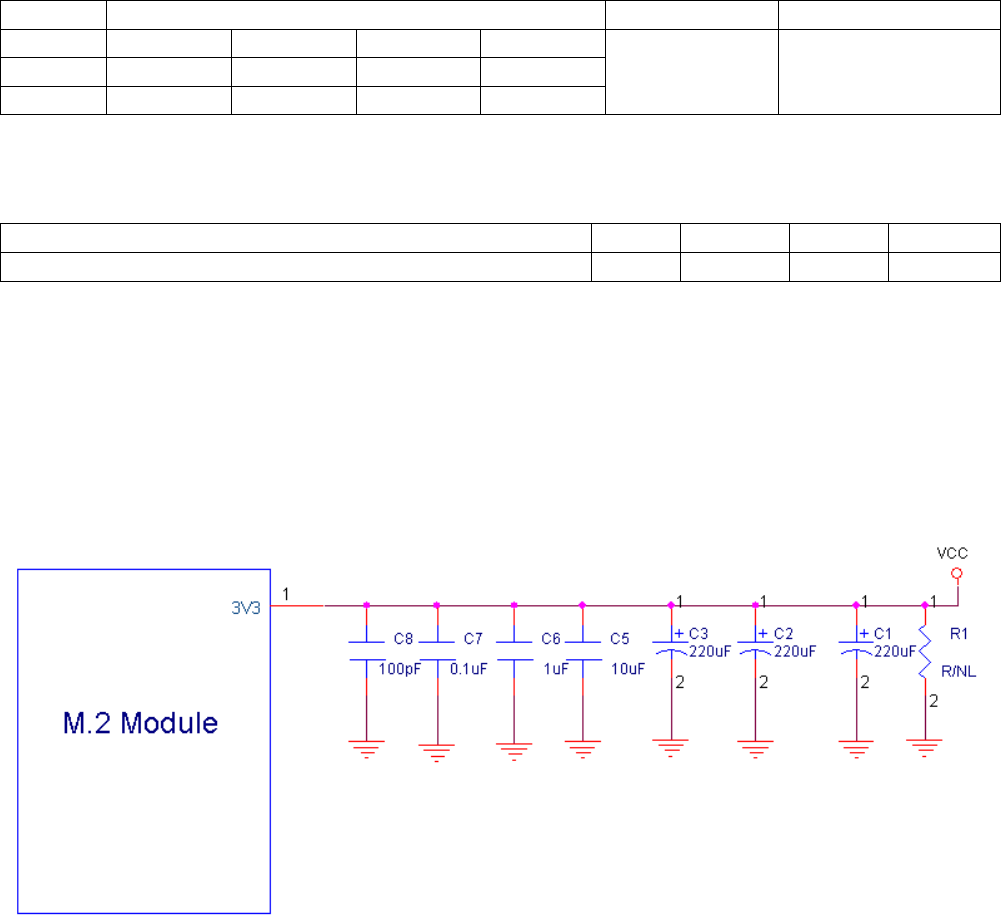
1.4.2 Power and ground
(1) Power Rail Parameters
Parameter Min Type Max Units
Operating voltage 3.135 3.3 3.465 Vdc
The operating voltage was defined in PCIe M.2_Rev0.7a standard as 3.3V+/-5%.
(2) 3.135 V is the minimum voltage supplied to LTE M.2 card by the host platform, and VCC
must never be under 3.135 V in any case. As our experiment, if we set the VCC=3.0V, the
M.2 card will power off when M.2 card working at +23dBm continue mode.
(3) Whenever the M.2 module works at 2G mode, the module transmits at the maximum
power (like +33dBm), the transient peak current may reach to 2.5 A.
We recommended design the VCC supply of host as below:
Remark: When the system power restarts, reserve R1 to discharge power.
(4) The LTE M.2 module provides 5 power pins and 11 Ground pins. To ensure that the LTE
module works normally, all the pins must be connected.
15
1.4.3 Full_Card_Power_Off
The M.2 LTE module can be controlled to power on/off by the Full_Card_Power_Of pin.
Item State M.2 card state
1 Low Powers off, It’s internally pulled down by 100K ohm resistor
2 High Powers on, it is 3.3V tolerant but can be driven by either 1.8V or
3.3V GPIO.
The recommended connections as below
1.4.4 USB interface
T77H468 module is compliant with USB2.0 in all three modes (Low speed, Full speed, and
high speed). When two devices are connected via a USB interface, one of the devices must
act as a host, and the other device must act as a peripheral. The host is responsible for
initiating and controlling traffic on the bus.
Figure 1-4-4 USB2.0 interface
16
1.4.5 W_DISABLE#
This control setting is implementation-specific and represents the collective intention of the
host software to manage radio operation. T77H468 provides a hardware pin (W_DISABLE#)
to disable or enable the radio. Besides, the radio can also be enabled or disabled through
software AT commands.
Item State Function (WWAN state)
W_DISABLE#1
Low WWAN Disabled (no RF operation allowed)
High WWAN Enabled (RF operation allowed), internally pull up
W_DISABLE#2
Low GPS Disabled (no RF operation allowed)
High GPS Enabled (RF operation allowed), internally pull up
1.4.6 LED Indication
The LED signal is provided to enable wireless communication add-in cards to provide status
indications to users via system provided indicators
(1) State of the LED# pin
Item State Definition Interpretation
1 Low The LED is emitting light. Radio is capable of transmitting.
2 High The LED is emitting no light. Radio is incapable of transmitting.
(2) Typical LED Connection in Platform/System
.
17
1.4.7 WoWWAN
The WAKE_ON_WWAN# signal is for power saving.
•LTE module always listening at very low power in idle mode
•LTE module will wake up mother board via ‘WoWWAN’ signal.
•The platform will power on when triggered by the LTE module.
The WAKE_ON_WWAN# signal is used to wake up the host. It is open drain and should be
pulled up at the host side. When the WWAN needs to wake up the host, it will output a one
second low pulse, shown in Figure 1-4-6.
Typical Connection in Platform/System
18
1.4.8 DPR (Dynamic Power Reduction)
The optional DPR signal is used by wireless devices to assist in meeting regulatory SAR
(Specific Absorption Rate) requirements for RF exposure. The signal is provided by a host
system proximity sensor to the wireless device to provide an input trigger causing a
reduction in the radio transmit output power.
The required value of the power reduction will vary between different host systems and is
left to the host platform OEM and card vendor to determine, along with the specific
implementation details. The assertion and de-assertion of DPR is asynchronous to any
system clock. All transients resulting from the proximity sensor need to be de-bounced by
system circuitry.
(1) State of the DPR
Item State Definition Interpretation
1 Low
Enable the SAR power back off.
Radio is capable of transmitting.
2 High
Disable the SAR power back off,
internally pull up
Radio is incapable of transmitting.
(2) Typical Connection in Platform/System
Remark:
a. The proximity sensor was controlled by the platform side.
b.
After DPR pin becomes low level, you can set the MAX TX power by AT commands..
19
1.4.9 USIM
The UIM contains parameters necessary for the WWAN device’s operation in a wireless
wide area network radio environment. The UIM signals are described in the following
paragraphs for M.2 add-in cards that support the off-card UIM interface.
(1) USIM card socket
It is recommended to take electrostatic discharge (ESD) protection measures near the USIM
card socket. The USIM socket should be placed near the NGFF interface (<100 mm),
because a long circuit may impact signal quality.
(2) UIM-PWR
UIM_PWR power supply can supply 1.8 V and 2.85 V power to UIM card and auto detects
follow SIM card type
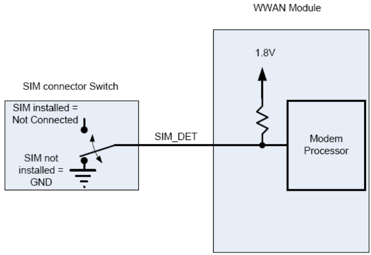
(3) SIM Detect
This signal is used to detect the insertion and removal of a SIM device in the SIM socket.
With a Normal Short SIM Card connector, PUSH-PUSH type, the detect switch is normally
shorted to ground when no SIM card is inserted. When the SIM is inserted, the
SIM_DETECT will transition from logic 0 to logic 1 state. The rising edge will indicate
insertion of the SIM card. When the SIM is pulled out, the SIM_DETECT will transition from
logic1 to logic 0. This falling edge will indicates the pulling out of the SIM card. The M.2
module monitoring this signal will treat the rising/falling edge or the actual logic state as an
interrupt, that when triggered, the module will act accordingly.

20
1.4.10 Antenna Control
T77H468 provides GPIO control signals for external antenna tuner application. The function
is under development for customization. ANTCTRL (0-3) are provided to allow for the
implementation of antenna tuning solutions. The number antenna control lines required will
depend on the application and antenna/band requirements.
Foxconn general design for WWAN module with two control signals.
ANTCTL0
ANTCTL1
Frequency (MHz)
Band support
0 0 880 ~ 960 Band8 (WCDMA) + GSM900 + High Bands
0 1 791 ~ 894 Band5 (WCDMA, LTE) + GSM850 + High Bands
1 0 746 ~787 Band13 (LTE) + High Bands
1 1 704 ~746 Band17 (LTE) + High Bands
1.4.11 Coexistence
COEX1, COEX2 and COEX3 are provided to allow for the implementation of wireless
coexistence solutions between the radio(s) on the M.2 Card and other off-card radio(s).
These other radios can be located on another M.2 Card located in the same host platform or
as alternate radio implementations (for example, using a PCI Express M.2 CEM or a
proprietary form-factor add-in solution).
Reserve for future extension, please contact with us if need to use these Pins.
Item Signal name GPIO from MDM9x15 Description
COEX1 LTE_ACTIVE
GPIO_67
TBD
COEX2 LTE_FRAME_SYNC
GPIO_66
TBD
COEX3 LTE_WLAN_PRIORITY
GPIO_65
TBD
21
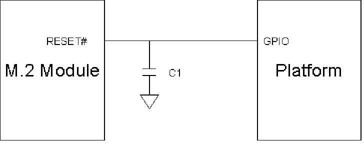
1.4.12 RESET#
Asynchronous RESET# pin, active low. Whenever this pin is active, the modem will
immediately be placed in a Power On reset condition. Care should be taken not to activate
this pin unless there is a critical failure and all other methods of regaining control and/or
communication with the WWAN sub-system have failed.
The Reset# signal is relatively sensitive, it is recommended to install one capacitor
(10~100pF) near to the M.2 card pin.
22
2. Hardware features
T77H468 consists of the following key engine components, in addition to the required
front-end RF and other discrete components.
Modem engine
■ Soft Baseband: MDM-9615
■ RF: WTR1605L
■ Power: PM8018
Connectivity engine
■ USB: USB2.0 high-speed
■ USIM: located off board
■ Antenna: connectors for the off board antennas
2.1 Mobile Data Modem
The MDM9615 chipset solution integrates powerful digital signal processors (DXPs) into any
market-proven wireless modem, offering increased processing capacity and lower power
consumption. They are complete system solutions that operate on networks worldwide. The
major functions of MDM9615 used on T77H468 are listed below:
❒ Processor:
- Manufactured in 28nm CMOS process
- System uP (Cortex-A5+L2 cache at up to 550MHz)
- ARM7 processor for the RPM
❒ Memory:
- External memory (16KB for security)
EBI1: 1Gb LPDDR1
- External memory
EBI2: 2Gb NAND flash
❒ Air interface:
- WCDMA (R99, HSDPA, HSUPA, HSPA+, DC-HSPA+)
- CDMA (1x, EV-DOr0, EV-DOrA, EV-DOrB)
- LTE (R9 Cat3, FDD)
- GSM (GSM R99, GPRS, EDGE)
- GPS/Glonass
❒ Advance RX operation:
- Mobile receive diversity (WCDMA, CDMA and LTE)
23
❒ Connectivity:
- USB 2.0 HS with built-in USB PHY
- UART interface
- UIM support (dual voltage)
2.2 RF transceiver
The WTR1605 device is a highly integrated and versatile RF CMOS transceiver IC that can
be used in multimode, multiband applications – including Rx diversity. The WTR1605 IC is
the RF transceiver IC within compatible Qualcomm MDM9615 chipsets.
The WTR1605 IC integrates advanced receive and transmit features into a 4.91 × 5.47 ×
0.63 mm package to simplify handset design, minimize parts count, and reduce DC power
consumption. These advanced Rx/Tx features include:
Multimode, multiband RF transceiver functions:
GNSS receiver functions
Fully integrated LO generation and distribution circuits to support all the RF operating
band and mode combinations
Primary, diversity, and GNSS receivers that can operate simultaneously
Tx power detector for monitoring the transmit power levels
The GSM receiver can share the secondary paths with CDMA, WCDMA, and LTE
diversity receivers
Qualcomm’s intelligent receiver technology for CDMA modes:
Low operating voltages that help save battery current and allows the WTR IC power to
be supplied by the PMIC’s switching mode power supply (SMPS) circuits for even
greater power savings
2.3 Power management IC
T77H468 system uses the Qualcomm PM8018. Qualcomm has worked with Maxim
Integrated Products Inc. to develop a custom PMIC solution for use with the T77H468
platform.
24
2.4 Antenna Design
2.4.1 Antenna specification
T77H468 also provides connectivity for off board antennas. The antennas and their
connection interface for this device satisfy the requirements specified in the PCI Express
M.2 Specification Revision 0.7a, Version 1.0 standard. The antenna elements are typically
integrated into the notebook/ultrabook /tablet and connected to T77H468 module via flexible
RF coaxial cables. T77H468 provides two RF connectors (MHF type), one for the primary
transmitter/receiver port and the other for the diversity receiver and GNSS.
To ensure stable RF performance, customer must assemble adequate antenna according to
the antenna specification.
Table 2-1 Main antenna specifications
Parameter Min. Typ. Max. Units Notes
Cable loss / / 0.5 dB Maximum loss to antenna
Impedance / 50 / ohm Antenna load impedance
VSWR / / 3:1 / Maximum allowed VSWR of antenna
Table 2-2 Aux antenna specifications
Parameter
Gain Maximum gain and uniform converge in high angle elevation
and zenith. Gain in the azimuth is not desired.
Average 3D gain >-5dBi
VSWR Typical value <3:1
Isolation(diversity to Main)
>10dB in all related bands
Polarization Any
2.4.2 Antenna location and mechanical design.
To ensure customer has a clear knowledge of the two antennas, check below product
picture.
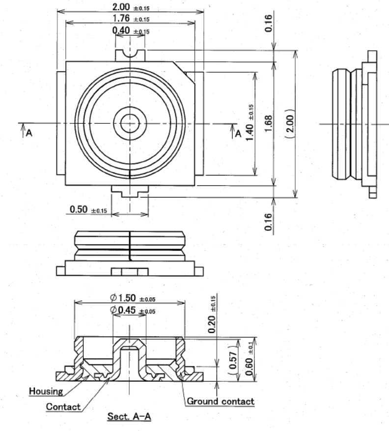
Figure 2-1 Antenna connector location and type
Figure 2-2 RF connectors
25
26
Figure 2-3 RF receptacles
27
3. Mechanical Specifications
3.1 Overview
T77H468 is compatible with the PCI Express M.2 Specification 3042 type 75-pin card
edge-type connector. Refer to Electromechanical Specification Revision 0.7a, Version 1.0
with Input Power and Voltage Tolerance ECN for more details.
3.2 Mechanical constraints
Figure 3-1 shows the mechanical constraints of T77H468 (3042-S3-B)
28
3.3 M.2 card assembly
Figure 3-2 shows Stack-up Mid-Line (In-line) Single Sided Module for 1.5 Maximum
Component Height, refer to section 2.4.8.3.1 of PCIe M.2_Rev0.7a standard.
Remark:
a. 2.4mm maximum above mother board
b. Cut area of main board under M.2 module
c. Need to add thermal pad between M.2 module and mechanical component (like material
shielding) for thermal dissipation.
29
3.4 Connector assembly
a. Mate the connector vertically as much as possible. Adjusting the mating axis of plug
and receptacle. Do not slant mate.
.
b. Unmating: In case of unmating by pulling tool. Use the pulling tool as the following
drawing, and pull plug to vertical direction as directly as possible
c. Pulling tool(Unit:mm)

30
4. Electrical Specifications
4.1 Recommended operating conditions
Table 4-1 Recommended operating conditions
Parameter Min Type Max Units
Storage temperature -30 +25 +85 °C
Recommend operating temperature
(3GPP compliant) -10 +25 +60 °C
Extend operating temperature
(operational, non-3GPP compliant) -20 +25 +70 °C
Operating voltage 3.135 3.3 3.465 Vdc
Operating T77H468 device under conditions beyond its absolute maximum ratings (Table
4-1) may damage the device. Absolute maximum ratings are limiting values to be
considered individually when all other parameters are within their specified operating ranges.
Functional operation and specification compliance under any absolute maximum condition,
or after exposure to any of these conditions, is not guaranteed or implied. Exposure may
affect device reliability
4.2 Power consumption
Table 4-2 Radio system power consumption
Test condition Sample
Test
Estimated power
range goal
(Typical)
Estimated power
range goal (Max.)
GSM in suspend mode 3.8mA <5mA
GSM (Tx=33dBm single slot) 310mA <500mA <2800mA
WCDMA in suspend mode 3.3mA <5mA
WCDMA (Tx=24dBm) 697mA <800mA <1100mA
CDMA in suspend mode 3.3mA <4mA
CDMA (Tx=24dBm) 610mA <700mA <1000mA
LTE in suspend mode 4.2mA <5mA
LTE (16QAM) Tx=23 dBm 735mA <900mA <1200mA
GPS/GNSS tracking 135mA <150mA <300mA
Connected standby 2.7mA <3mA

31
5. RF performance specifications
Radio performance for T77H468 is given in the following sections, including RF receiver, RF
transmitter.
5.1 RF maximum Tx power specifications
Table 5-1 Maximum transmit power
Specification Power class/
control level Min. Typ. Max. unit
LTE (B2) Class 3 21 23 24 dBm
LTE (B4) Class 3 21 23 24.5 dBm
LTE (B5) Class 3 21 23 24 dBm
LTE (B13) Class 3 21 23 24.5 dBm
LTE (B17) Class 3 21 23 24.5 dBm
LTE (B25) Class 3 21 23 24 dBm
WCDMA (B1) Class 3 21 24 25 dBm
WCDMA (B2) Class 3 21 24 25 dBm
WCDMA (B4) Class 3 21 24 25 dBm
WCDMA (B5) Class 3 21 24 25 dBm
WCDMA (B8) Class 3 21 24 25 dBm
CDMA (BC0) Class 3 23 24 25 dBm
CDMA (BC1) Class 2 23 24 25 dBm
GSM850/900 Class4 31 32 33 dBm
GSM1800/1900 Class1 28 31 30 dBm
GPRS 850/900 Class4 31 32 33 dBm
GPRS 1800/1900 Class1 28 29 30 dBm
EDGE 850/900 ClassE2@PCL8
25 26 27 dBm
EDGE 1800/1900 ClassE2@PCL2
24 25 26 dBm
Remark:
Above table is for general application, please inform us if you have any further requirement.
32
5.2 RF min. Rx sensitivity specifications
Table 5-2 Conducted min. receiver sensitivity
Specification Min. Typ. Max.
(compliance with standard) unit
LTE (B2)@10MHz / -101 -95 dBm
LTE (B4) @10MHz / -102 -97 dBm
LTE (B5) @10MHz / -102.5 -95 dBm
LTE (B13) @10MHz / -103 -94 dBm
LTE (B17) @10MHz / -102.5 -94 dBm
LTE (B25) @10MHz / -101 -93.5 dBm
WCDMA (B1) / -110 -106 dBm
WCDMA (B2) / -109 -104 dBm
WCDMA (B4) / -110 -106 dBm
WCDMA (B5) / -111 -104 dBm
WCDMA (B8) / -110 -103 dBm
CDMA (BC0) / -109 -104 dBm
CDMA (BC1) / -109 -101 dBm
GSM850/900 / -110 -102 dBm
GSM1800/1900 / -110 -100 dBm
GPRS 850/900 (CS1) / -110 -102 dBm
GPRS 1800/1900 (CS1) / -110 -100 dBm
EDGE 850/900 (CS5) / -107 -98 dBm
EDGE 1800/1900 (CS5) / -105 -98 dBm
GPS/GLONASS tracking sensitivity
/ -157 -152 dBm
Remark:
a. It has 3dB margin at least refer to 3GPP standard or CDMA standard.
b. The typical value of LTE was measured as combine Rx sensitivity which was follow test
setup of 3GPP standard (TS36.521 charter 7.2 and charter 7.3.5), the test setup is follow
TS36.508 Annex A Figure A.3.
SS
RX/TX
RX
UE under Test
RX/TX
Ior
Îor
Splitter/
combiner

33
6. Software Requirements
The software includes firmware, driver, configuration file and configuration utility for LTE
Card based on Qualcomm MDM9615+WTR1605L chipsets. Please refer to main features in
below table.
# Feature Feature description
1.1 Modem
1.1.1 LTE-FDD - Release 8
1.1.2 LTE-FDD - Release 9
(mandatory features)
1.1.3 DC-HSPA+ - Release 8
1.1.4 1x Advanced
1.1.5 EVDO Rev B
1.1.6 eHRPD
1.1.7 WCDMA
1.1.8 GERAN
1.1.9 SVLTE
1.1.10 WCDMA/GERAN: Protocols
– Rel-8: Support for E-UTRA
Detection
If LTE coverage is available and if UE is
able to detect the same (from a state
where we didn’t have any sync LTE cells),
it will inform upper layers. This is spec
requirement
1.1.11 LTE-eHRPD Mobility
1.1.12 Rel8 Fast Dormancy
1.1.13 Rel7 HSPA DTX/DRX
1.1.14 APT - for all modes (LTE
FDD/WCDMA, C2K)
1.1.15 Peripheral attachments -
WLAN for QCMobileAP and
SD card
1.1.16 Data call (Geran, WCDMA,
1X/EVDO, eHRPD and LTE)
1.1.17 SMS (GERAN,
WCDMA,1X/EVDO, eHRPD
and LTE)
1.1.18 Data interface- QMI QMI commands for UQCN download and
selection. Add commands to manage
UQCNs, set the device in Download
mode.
1.1.19 Power grid /PAM table
config support
1.1.20 Support for Gobi RF configs
Support for Gobi WTR1605 configurations
1.1.21 UQCN Feature support UQCN Feature support ,Carrier specific
UQCNs implementation / UQCN
generation tools

34
1.1.22 Configurable RRC band
scan order, also add support
for LTE cfgs
1.1.23 Saving MRU/ Band scan etc.
info while in
suspend/resume/power-save
states - WCDMA
1.1.24 Gobi - Saving MRU/band
scan info (3GPP2)
1.1.25 Gobi - Saving MRU/band
scan info (GERAN,
WCDMA)
1.1.26 Gobi - Add QMI CAT
Command for terminal
profile property.
Add
QMI_CAT_SEND_ENVELOP_CMD_RSP.
Add optional TLV in
QMI_CAT_SEND_ENVELOP_CMD_RSP
to report envelope response from card in
raw format and corresponding status
words
1.1.27 Multiple carrier support in
NV Provides the ability for a single modem
image to support multiple carriers via
per-carrier configuration files that are
downloaded to the modem. This is a Gobi
modem capability
1.2 Modem (1X)
1.2.1 Enable complete IS-683C
OTA message support FEATURE_IS683C_OTASP makes the
following messages compliant with
IS683C standard:
Protocol Capability Response message
SSPR Configuration Request/Response
message
1.2.2 OTASP support for all band
classes Expand the OTASP support to all the
bands supported by the 3GPP2
C.S0057-B
1.2.3 Multimode: OTASP/OTAPA
–Runtime Detection of
OTASP Numbers
Provide capability of using custom
numbers with OTASP calls via UI through
Centralized Call Control support
1.3 Modem (EVDO)
1.3.1 Dedicated Data Transfer
Mode (DDTM) Allows the user to control the 1X access
at runtime when the 1xEV-DO data call is
made
1.3.2 EV-DO Data Activity Based
Adaptive Receive Diversity Disable EV-DO diversity when no FL data
is arriving. When data resumes,
immediately bring up diversity. This saves
power during the period of waiting for
dormancy for applications that don't
explicitly close the connect
1.3.3 Rx Diversity during 1x
Access Enable 1x Rx Diversity during 1x Access if
Rx Diversity for Traffic Has Been Enabled

35
1.3.4 1X EV-DO Rev B (with QOS
for handsets) The multi-carrier version of 1xEV-DO in
which up to three carriers are supported
on the forward and reverse links; QoS
added for handsets
1.3.5 3 Carrier Rev B over 5x
Bandwidth 3 Carrier rev B over 5x bandwidth
1.3.6 Max Bandwidth Support Support calls where the AN assigns outer
carriers that are 5.16 MHz apart
1.3.7 Rev B physical layer FL
rates Enhanced flow rates on FL
1.4 Modem (eHRPD)
1.4.1 eHRPD: eHRPD <-> 1x
handoff Allows the mobile to move between areas
of eHRPD coverage and 1x coverage
(and vice-versa).
1.4.2 eHRPD: eHRPD <-> HRPD
handoff When moving from 1x/HRPD to eHRPD,
AT should not send ULN. When moving
back from eHRPD to HRPD, also AT
should not send ULN.
1.5 Modem (Geran)
1.5.1 GERAN 3GPP Rel-8 Spec
compliance GERAN compliant with Rel-8 spec
versions
1.5.2 NACC, Ext UL TBF Rel Network-Assisted Cell Selection for faster
cell reselection and Extended UL TBF
Release to extend the UL TBF and reduce
the incidence of idle activity between
packet transfer activities
1.2.3 PFC/PFI Packet Flow Context/Packet Flow
Identifier - Allows identity tagging of RLC
blocks to identify separate QoS streams at
the radio link layer
1.5.4 EDGE MSC12 Original legacy EDGE support with
Multislot Class 12 capability
1.5.5 GPRS/EDGE MSC12-EDA Extended Dynamic Allocation to permit
allocation of more than two uplink
timeslots for GPRS/EDGE
1.5.6 Enh DL RLC/MAC
Segmentation Permits reception of MAC control
messages that exceed one radio block
capacity in length
1.5.7 Enhanced Ext UL TBF Per Ext UL TBF, with the addition that
dummy block transmission is punctured
for current saving purposes
1.5.8 2G PS handover Packet-switched equivalent of CS
handover to ensure faster cell change and
improved throughput
1.5.9 Encryption: GEA3 New packet-switched cipher algorithm
1.5.10 WCDMA/GERAN: Band
Scan – Run-time
Configurable RRC Band
Scan Order
Run-time configurable RRC band scan
order

36
1.5.11 WCDMA/GERAN: Power
and Network
Optimizations – Frame
Early Termination for Power
Optimization
With pragmatic reception approach,
decode partial TTI and terminate frame
early to reduce power consumption
1.5.12 WCDMA/GERAN:
Protocols – MRAB-Pack-1
Enhancements
These UE enhancements will reduce
Multi-RAB Call Drops. The following
optimizations are planned under
MRAB-Pack-1: 1) Configuration of the
minimum set of TFCs: Optimize the way
that PS-only TFCs are selected for UL
transmission in power limited conditions(2
flavors) 1-EUL) Smart application of
minimum E-TFCI : Optimize utilization of
Minimum E-TFCI in power limited
conditions 4) MRAB Back-off: Preventing,
or reducing the establishment of data
connections on top of existing voice
connections in power limited conditions 6)
TVM Back-off : Blocking traffic volume
events (Event 4a) for MRAB calls in power
limited conditions
1.6 Modem (UMTS)
1.6.1 Cat 10 HSDPA Rel-5 Category 10 HSDPA, allowing for
physical layer throughputs up to 14.4
Mbps.
1.6.2 Cat 6 HSUPA Rel-6 Category 6 HSUPA, allowing for
physical layer throughputs up to 5.76
Mbps.
1.6.3 Cat 14 HSPA+ Cat 14 HSPA+ 64-QAM HSDPA,
allowing for physical layer throughputs up
to 21 Mbps
1.6.4 DC-HSPA+ Dual Carrier – HSPA+, allowing for
physical layer throughputs up to 42 Mbps
1.6.5 HSUPA 10ms TTI (2 Mbps) HSUPA 10 ms TTI up to 2 Mbps in UL
physical layer
1.6.6 HSUPA 2ms TTI (5.76
Mbps) HSUPA 2ms TTI up to 5.76 Mbps in UL
physical layer
1.6.7 E-FDPCH E-FDPCH Rel-7 enhancement to the
Rel-6 FDPCH (fractional DPCH) in soft
handover scenarios; fractional DPCH was
added in Rel-6 to optimize the
consumption of downlink channelization
codes - Allowing more users to share the
channel
1.6.8 Enhanced L2 Support for flexible sized PDUs at RLC DL
and PDU segmentation at MAC-HS level,
on the HSDPA downlink to allow for higher
data rates in Rel-7
1.6.9 CPC-DTX Allows for breaks in transmission during

37
HSUPA for power consumption benefit
and UL interference reduction.
1.6.10 Q-ICE Advanced UMTS receiver performing
iterative equalization and interference
cancellation in support of HSPA+
1.6.11 SCH-IC Cancelling the interference from the
synchronization channel for improved
HSDPA performance
1.7 Modem (LTE)
1.7.1 Rel-9: Mandatory LTE
Features Support for Release 9 Mandatory
Features
1.7.2 Bandwidth support 1.4, 3, 5,
10, 15, 20 MHz Per 3GPP standard
1.7.3 Standalone Security NAS & RRC security for LTE
1.7.4 CMAS for LTE Commercial Mobile Alert System for LTE
1.7.5 ETWS (Earthquake Tsunami
Warning System) - LTE Support for ETWS notification in LTE
1.7.6 Intra-Freq Connected mode
mobility Support for 1X2 MISO (1Tx and 2Rx for
two downlinks simultaneously)
1.7.7 Intra-Freq Idle mode mobility
Support for 1X2 MISO (1Tx and 2Rx for
two downlinks simultaneously)
1.7.8 Inter-Freq mobility Mobility within LTE band/bandwidth
1.7.9 Connected mode DRX Exercising DRX cycle while in LTE
Connected mode
1.7.10 Sleep Exercising DRX cycle while in LTE Idle
mode
1.7.11 eHRPD -> LTE Idle mode
reselection Mobility from eHRPD to LTE in Idle mode
based on LTE neighbor cell
measurements
1.7.12 E-UTRA RRC_IDLE ->
eHRPD Idle Reselection from idle LTE to idle eHRPD
1.7.13 IRAT SON ANR UE IRAT support for Self Organizing
Networks and Automatic Neighbor
Relation
1.7.14 LTE -> eHRPD (Redirections
without measurement gaps -
blind)
Redirections from LTE connected ->
eHRPD Idle without measurements (blind
redirection)
1.7.15 LTE -> eHRPD (Redirections
based on measurements
gaps)
Redirections from LTE connected to
eHRPD idle based on measurements
during gaps intervals
1.7.16 LTE -> 1x Connected mode
measurements Perform measurements on 1x side during
LTE Connected mode state.
1.7.17 LTE -> 1x Redirection Redirection from LTE connected to 1x idle
1.7.18 LTE -> 1x Reselection Idle mode reselection from LTE idle to 1x
idle
1.7.19 UMTS -> LTE Redirections
(no measurements) Redirection from UMTS to LTE (blind - no
measurements)
1.7.20 UMTS -> LTE Redirections
(with measurements) Redirection from UMTS Connected mode
to LTE based on LTE measurements

38
during WCDMA Compressed mode gaps
1.7.21 GERAN -> LTE Redirections
(no measurements) Redirection from GERAN to LTE (blind -
no measurements)
1.7.22 LTE <-> GERAN Idle mode
mobility (cell reselection) Idle mode reselection from LTE idle to
GERAN idle
1.7.23 LTE <-> UMTS Idle mode
mobility (cell reselection) Idle mode reselection from LTE idle to
UMTS idle
1.7.24 LTE -> UMTS PS Handover UE does a PS handover under network
direction from LTE to
UMTS
1.7.25 LTE -> UMTS Redirections
(with measurements) 2012 Redirection from LTE connected to UMTS
with measurements on UMTS
1.7.26 LTE/GW Data Silent Redial
for InterRAT During inter RAT transitions between LTE
and WCDMA/GPRS, data calls that are
locally rejected on source RAT will be
redialed by Data Services mode handler
on target RAT
1.7.27 Multimode: LTE –
Attach/Detach PS during
Voice Call or SMS
Support disabling of PS capability during
voice call/SMS and removing LTE when
PS is removed (Detach) and add LTE
again when PS is added (attach)
1.7.28
TDD-LTE
1.8 Modem (System Determination)
1.8.1 Frequency Scan and System
Selection within LTE Ability to do band scan and also power-up
system selection
1.8.2 LTE BPLMN support Support for PLMN search in background
while LTE is active
1.8.3 LTE Connected mode OOS Support System Operation mode (Online,
LPM, POWER OFF, etc.) changes in LTE
Connected and Idle mode
1.8.4 System Selection across
LTE, UMTS, GERAN, 1x/DO Ability to select a particular RAT based on
a preferred RAT list
1.8.5 System Selection across
RATs, Standalone Security,
Dedicated EPS Bearer Mgmt
and Dormancy
Standard LTE features
1.8.6 Support of 256 UPLMN and
256 OPLMN entries in USIM UE can read 256 entries from each
preferred list. Together, it can read a
maximum of 512 PLMN entries from
preferred list.
1.8.7 Multi-mode System
Selection Facilitating system selection when UE
supports multiple modes
1.8.8 Multimode: System
Selection – Avoiding
Unnecessary Attach
Requests in A
3GPP+3GPP2 Multimode
UE
NAS will use a synchronous API call to
check with CM whether a PLMN is ok to
attach before starting attach procedure. If
API returns TRUE, NAS will do the
attaching and send SRV_CNF to CM. This
will be a preferred system so CM won’t

39
send STOP_MODE for less preferred
system. If API returns FALSE,
CM_SRV_CNF with No Service
1.8.9 Carrier Specific BSR
Requirements Extensions to carrier specific set of
requirements for System Selection
1.8.10 Data Services:
eHRPD/LTE – Data System
Determination for Multiple
Radio Systems
Re-architect data call arbitration in Data
Services layers to remove race conditions
between various SW entities in modem
and CNE
1.8.11 WCDMA/GERAN: System
Selection – Prevent UE from
Sending Attach Request
Message Infinitely When
HPLMN Reject Attach
Request with Cause 14
If HPLMN rejects GPRS Registration with
cause # GPRS Services Not Allowed in
this PLMN (which it shouldn't as per
expectation from a well-behaved network),
UE keeps on attempting registration again
and again on same HPLMN RA. This
feature is to cover up for this network
misbehavior and reattempt GPRS
registration only on RA change
1.9 Modem (Data)
1.9.1
ATCOP
1.9.2 WCDMA/GERAN: ATCOP
3GPP – Enhancing The
Interface for Manual PLMN
Selection
Provide Manual PLMN Selection API
between CM/NAS and ATCOP to provide
the current serving status of the UE
1.9.3 IPHC IP header compression protocol as RFC
2509
1.9.4 DHCPv4 DHCPv4 This is to support for stateless
DHCPv4 protocol to get P-CSCF and
DNS addresses
1.9.5 Simple IPv4 Supports IPv4 address allocation and
release without IP mobility
1.9.6 Mobile IPv4
1.9.7 4 PDNs Support over
Multi-RmNet Provides the capability to an external AP
to support 4 PDNs through 4 RmNet
Connections to external processor
1.9.8 Dual IP on single RmNet UE shall support tethered RmNet to laptop
data call using Dual IP on single RmNet to
a single USB-end point
1.9.9 IP only Mode/Raw IP Mode RmNet laptop calls transfer IP packets
over USB or shared memory without
Ethernet framing; reduces CPU overhead
and speeds up call setup times (no ARP
duplicate detection)
1.9.10 Multi-RmNet Data Call This is support multiple tethered data calls
over multi-RmNet
1.9.11 DHCPv6
1.9.12 RmNet IPv6
1.9.13 Tethered IPv6 using DUN
over USB

40
1.10 Modem (Data: EVDO)
1.10.1 RLP: 1x EVDO Rev B This is to support Radio Link Protocol in
1xEV-DO Rev B
1.10.2 CDMA: 1X EVDO Rev B –
Enhanced PA Back off for
DO Rev B
Uses Tx power differential based PA back
off for multi-carrier assignment, and
improves a) multi-carrier
coverage/throughput on FL, and b) RL
data rate/throughput when multiple
carriers are assigned on FL
1.11 Modem (Data: eHRPD)
1.11.1 EAP-AKA' (prime) Authentication protocol using AKA' (prime)
over EAP transport for all air interfaces
1.11.2 eHRPD: Multiple PDN
Support Enhanced AMSS implementation to
support multiple VSNCP negotiations and
multiple VSNP data paths over one PPP
instance for eHRPD multiple PDN
connectivity; 3GPP2 eHRPD specification
(X.P0057-0-EHRPD-EUTRAN)
1.11.3 eHRPD: Optimized Silent
Redial and
DCTM4.0
Silent Redial of data call on eHRPD
system
1.11.4 Data Services: eHRPD –
Ignore PDN Inactivity Timer
for The Last PDN
The UE shall ignore the PDN Inactivity
timer when only one PDN connection
remains. Upon PDN Inactivity timer expiry,
if it is the last PDN connection, the UE
shall extend the timer, and shall not
initiate PDN disconnection
1.12 Modem (Data: LTE)
1.12.1 LTE: Data Call throttling This is to prevent UE from repeatedly
requesting PDN connections to the NW
when it encounters a failure in either
eHRPD or LTE connections
1.12.2 LTE: Default IPv4 Bearer
activation at attach Support for IPv4 data call in LTE
1.12.3 LTE: NW initiated QoS
1.12.4 LTE: UE initiated QoS
1.12.5 Dual IP Continuity Dual IP continuity across LTE and eHRPD
1.12.6 IPv4/IPv6 Continuity Dual IP continuity across LTE and eHRPD
1.12.7 LTE-eHRPD mobility: IPV4
Session Continuity IPv4 session continuity across LTE and
eHRPD
1.12.8 LTE-eHRPD mobility: IPV6
Session Continuity IPv4 session continuity across LTE and
eHRPD
1.12.9 LTE: W/G IP session
Continuity IP session continuity across LTE and W/G
1.12.10
LTE: MIMO – LTE TDD
4-Port Processing LTE TDD 4x2 MIMO antenna
configuration support (4x2 transmit
diversity)
1.12.11
LTE: MBMS – LTE TDD
MBSFN Awareness Ability to ignore MBSFN symbols in LTE
TDD subframes while maintaining unicast

41
performance
1.12.12
LTE: Mobility – LTE TDD
Inter-Freq Connected Mode
Handover
LTE TDD inter-frequency connected mode
handover with measurements covering
multiple EARFCN's in the same or
different bands as well as different
bandwidths in the same EARFCN
1.12.13
LTE: DRX –LTE TDD
Connected Mode DRX
without Sleep
Improve power consumption by turning off
modem/RF components during connected
mode DRX periods. No Sleep support
1.12.14
LTE: DRX – LTE TDD
Connected Mode DRX with
Sleep
Enhanced and optimized power
consumption over 1.12.13 using sleep
support in Connected mode DRX periods
1.12.15
LTE: Emergency Services –
LTE NAS Support for Control
Plane LTE Positioning
Protocol
Enable Location Positioning Protocol
capabilities through NAS signaling as well
as to create an API providing transport
services for GPS signaling
1.12.16
Data Services – LTE-eHRPD
Mobility Support of APN
Class and APN Bearer in
Application Profile over LTE
To support APN Bearer in Application
Profile over LTE
1.13 Modem (VoLTE)
1.13.1 LTE: VoLTE – Forking
Support Support for parallel and sequential forking
in IMS VoLTE
1.13.2 LTE: QMI – VoLTE: QMI
Indication for Remote Party
on Hold
Indication provided when remote party
places call on hold
1.13.3 LTE: VoLTE – Session Timer
support on VoLTE Session Timer Support on VoLTE/QIPCall
to be
implemented/tested for Phase3
1.13.4 LTE: VoLTE – VT Call
Supplementary Services Support for VT call supplementary
services:
1. Call Hold/Resume
2. Call waiting
a. Between two VT/VS calls
b. Between VT/VS call and VOIP call
c. Between VT/VS call and 1x call
3. Call conference
4. Caller id Presentation/Restriction5.
DTMF
1.13.5 LTE: VoLTE – Early Media
Support Support for early media in VoLTE
1.13.6 LTE: VoLTE – VoLTE
Support in RIL, Android
Telephony and QMI_VOICE
VoLTE support in RIL, Android Telephony
and QMI_VOICE
The Linux features described in this chapter are:
Device Drivers
Modem Interface

42
Linux Kernel and BSP
Other
Power Management
USB
Validated Configuration
Development/Debug
Table 5-1 Linux features
# Feature Feature description
2.1 Device Drivers
2.1.1 UART Driver Peripheral driver for Universal
Asynchronous Receiver/Transmitter
2.1.2 I2C Driver Peripheral driver for Inter-IC bus up to
100 kbps or 400 kbps for Fast mode
2.1.3 I2S Driver Peripheral driver for Inter-IC sound
bus. I2S is an industry standard
(invented by Philips) three-wire
interface for streaming stereo audio
between devices. Typical applications
include digital audio transfer between
a CPU/DSP and a DAC/ADC. The I2S
core allows a Wishbone master to
stream stereo audio to and from I2S
capable devices.
2.1.4 SD/MMC Interface Secure digital memory support.
2.1.5 SDIO Secure digital input/output
Two controller ports
Up to 48 MHz
4-bit interface
Interface through Linux MMC stack
2.1.6 WLAN driver Support for wireless networking over
SDIO
2.1.7 SPI Driver Peripheral driver for Serial Peripheral
Interface bus can use Data Mover and
clock up to 26 MHz
2.1.8 SSBI Driver Driver for SSBI (Single-Wire Serial
Bus Interface) bus hardware cores
2.1.9 2KB. 4KB, and 8KB size pages
SLC NAND x8 and x16 Flash driver support for 8-bit and
16-bit Single Level Cell (SLC) NAND
devices with 2k page size
2.2 Modem Interface
2.2.1 AT Command Support (GCF) Support for AT commands required for
GCF testing. See document
80-VR432-1 for details.
2.2.2 Dial-up Networking over USB Support for tethered dial-up
networking over USB
2.2.3 QMI QMI is to be used by 3rd party
operating systems to configure the

43
modem data stack
2.2.4 Multimode: QMI – Add One
Field toDetermine if Record is
Read Only or Read-Write in
QMI_PBM_RECORD_READ_IND
Adding a field to know whether the
record is read only or read-write in
QMI_PBM_RECORD_READ_IND.
This is required instead of determining
through UIM for this information. This
feature tells the clients if a particular
phonebook is writeable or not and if
not what validation is required
2.2.5 Multimode: QMI – WMS SEND
RAW Async Command Add support so raw-send and
send-ack can be asynchronous
2.2.6 Data Interface: IMS – VT: Support
Rm Socket Interface between AP
and Modem
Provides a Rm Socket Interface
between AP and Modem for VT
Support
2.2.7 Modem Interfaces: QMI – Provide
Number of USIM Entries per
Contact
PBM support for providing the number
of USIM contacts that can be
associated with a contact stored on
the SIM card. USIM contacts include
E-mail, Additional Number, Group
name and SNE
2.2.8 Multimode: Emergency Services
– RAT Based ECC Number
Handling
CM acquires a RAT based on ECC list
for emergency call and PBM
maintains ECC list per RAT and
provide new API for call type
resolution
2.2.9 IMS Voice Loopback Mode
Support Support loopback mode for voice
packets in IMS
2.2.10
IMS – Call Failure Code & Call
End Reason Provided to UI
through CM
Call failure code & Call end reason
provided to UI through CM
2.2.11
SIM Hotswap Feature allows inserting or removing a
SIM while the device is powered on
2.3 Linux Kernel and BSP
2.3.1 Base Linux Kernel port kernel version supported: 3.0
2.3.2 Secure Boot SBL2 loads all subsystem firmware
2.3.3 Data Mover (DMOV) Driver that interfaces with the
Qualcomm Data Mover hardware.
2.3.4 Exception handler Linux kernel handlers for A5 CPU
exceptions, kernel panic, etc.
2.3.5 Watchdog No subsystem restart, A5 watchdog
bark and bite handlers, modem
watchdog bite (system resets), RPM
watchdog bite (system resets),
restarts in Download mode based on
NV flag
2.3.6 Network Stack Support Linux network stack provides IPv4 and
IPv6 support
2.3.7 RAM File System RAM file system(s) supported for initrd
2.3.8 FAT32 FAT32 file system (for SD)

44
2.3.9 YAFFS2 NAND
2.3.10
FOTA FOTA is an application used for
upgrading firmware image over
the air
Federal Communication Commission Interference Statement
This device complies with Part 15 of the FCC Rules. Operation is subject to the
following two conditions: (1) This device may not cause harmful interference, and (2)
this device must accept any interference received, including interference that may
cause undesired operation.
This equipment has been tested and found to comply with the limits for a Class B
digital device, pursuant to Part 15 of the FCC Rules. These limits are designed to
provide reasonable protection against harmful interference in a residential installation.
This equipment generates, uses and can radiate radio frequency energy and, if not
installed and used in accordance with the instructions, may cause harmful interference
to radio communications. However, there is no guarantee that interference will not
occur in a particular installation. If this equipment does cause harmful interference to
radio or television reception, which can be determined by turning the equipment off
and on, the user is encouraged to try to correct the interference by one of the following
measures:
-Reorient or relocate the receiving antenna.
-Increase the separation between the equipment and receiver.
- Connect the equipment into an outlet on a circuit different from that
to which the receiver is connected.
-Consult the dealer or an experienced radio/TV technician for help.
FCC Caution: Any changes or modifications not expressly approved by the party
responsible for compliance could void the user's authority to operate this equipment.
This transmitter must not be co-located or operating in conjunction with any other
antenna or transmitter.

Radiation Exposure Statement:
This equipment complies with FCC radiation exposure limits set forth for an
uncontrolled environment. This equipment should be installed and operated
with minimum distance 20 cm between the radiator & your body.
This device is intended only for OEM integrators under the following conditions:
1) The antenna must be installed such that 20cm is maintained between the
antenna and users, and
2) The transmitter module may not be co-located with any other transmitter or
antenna.
As long as 2 conditions above are met, further transmitter test will not be required.
However, the OEM integrator is still responsible for testing their end-product for any
additional compliance requirements required with this module installed
IMPORTANT NOTE: In the event that these conditions can not be met (for example
certain laptop configurations or co-location with another transmitter), then the FCC
authorization is no longer considered valid and the FCC ID can not be used on the
final product. In these circumstances, the OEM integrator will be responsible for
re-evaluating the end product (including the transmitter) and obtaining a separate FCC
authorization.
End Product Labeling
This transmitter module is authorized only for use in device where the antenna may be
installed such that 20cm may be maintained between the antenna and users. The final
end product must be labeled in a visible area with the following: “Contains FCC ID:
RI7LN931NAG”. The grantee's FCC ID can be used only when all FCC compliance
requirements are met.
Manual Information To the End User
The OEM integrator has to be aware not to provide information to the end user regarding
how to install or remove this RF module in the user’s manual of the end product which
integrates this module.
The end user manual shall include all required regulatory information/warning as show in
this manual.