Telit Communications S p A UE910NA 2G/3G Module User Manual HEADING 2
Telit Communications S.p.A. 2G/3G Module HEADING 2
Contents
- 1. Users_guide_V2
- 2. Users Manual
Users Manual
D-305735 PowerMaster 360 Installer's Guide 1
PowerMaster 360
Version 18
Installer's Guide
Table of Contents
1. INTRODUCTION ................................................. 3
1.1 System Features .......................................... 3
2. CHOOSING THE INSTALLATION LOCATION .. 6
3. INSTALLATION .................................................. 7
3.1 Connections and LED Indications .............. 7
3.2 Inserting the Battery .................................... 8
3.3 PowerManage 360 Connections ................. 9
3.4 GSM Connection and Configuration ......... 10
3.5 SIM Card Insertion ..................................... 10
3.6 PowerMaster 360 Prerequisites ................ 10
3.7 Enrolling / Deleting a Z-Wave Device ....... 10
3.8 Panel Reset................................................. 11
3.9 Factory Default Restore ............................. 11
4. PROGRAMMING .............................................. 12
4.1 General Guidance ...................................... 12
4.1.1 Navigation .......................................... 12
4.1.2 Feedback Sounds .............................. 14
4.2 Entering the "Installer Mode" and Selecting
a Menu Option .................................................. 14
4.2.1 Entering the "Installer Mode" if "User
Permit" is enabled ....................................... 14
4.2.2 Selecting options ................................ 15
4.2.3 Exiting the Installer Mode ................... 15
4.3 Setting Installer Codes .............................. 15
4.3.1 Identical Installer and Master Installer
Codes ......................................................... 16
4.4 Zones / Devices .......................................... 16
4.4.1 General Guidance & Zones/Devices
Menu Options ............................................. 16
4.4.2 Adding New Wireless Devices ........... 17
4.4.3 Deleting a Device ............................... 21
4.4.4 Modifying or Reviewing a Device ....... 21
4.4.5 Replacing a Device ............................ 22
4.4.6 Configuring Soak Test Mode .............. 22
4.4.7 Defining Configuration Defaults for
"Device Settings" ........................................ 23
4.4.8 Updating Devices after Exiting Installer
Mode ........................................................... 23
4.5 Control Panel .............................................. 24
4.5.1 General Guidance – "Control Panel"
Flow-Chart & Menu Options ........................ 24
4.5.2 Configuring Arming/Disarming and
Exit/Entry Procedures .................................. 25
4.5.3 Configuring Zones Functionality ......... 26
4.5.4 Configuring Alarms & Troubles ........... 27
4.5.5 Configuring Sirens Functionality ......... 28
4.5.6 Configuring Audible & Visual User
Interface ...................................................... 28
4.5.7 Configuring Jamming and Supervision
(Missing device) .......................................... 29
4.5.8 Configuring Miscellaneous Features ... 30
4.6 Communication .......................................... 31
4.6.1 General Guidance – "Communication"
Flow-Chart & Menu Options .......................... 31
4.6.2 Configuring GSM-GPRS (IP) - SMS
Cellular Connection ..................................... 32
4.6.3 Configuring Events Reporting to
Monitoring Stations ...................................... 33
4.6.4 Configuring Events Reporting to Private
Users ........................................................... 36
4.6.5 Configuring Motion Cameras for Visual
Alarm Verification ........................................ 36
4.6.6 Configuring Upload / Download Remote
Programming Access Permission ................ 37
4.6.7 Broadband .......................................... 38
4.7 Custom Names ........................................... 39
4.7.1 Custom Zone Names .......................... 39
4.8 Diagnostics ................................................. 40
4.8.1 General Guidance – "Diagnostics" Flow-
Chart & Menu Options ................................. 40
4.8.2 Testing Wireless Devices ................... 40
4.8.3 Testing the GSM module .................... 42
4.8.4 Testing the SIM Number ..................... 42
4.8.5 Testing the Broadband/PowerLink
Module ........................................................ 43
4.9 User Settings .............................................. 43
4.10 Factory Default ......................................... 44
4.11 Serial Number ........................................... 44
4.12 Partitioning................................................ 44
2 D-305735 PowerMaster 360 Installer's Guide
4.12.1 General Guidance – "Partitioning"
Menu ........................................................... 44
4.12.2 Enabling / Disabling Partitions .......... 44
4.13 Operation Mode ........................................ 45
4.13.1 General Guidance – "Operation Mode"
Menu ........................................................... 45
4.13.2 Select setting ................................... 45
4.13.3 BS8243 Setup .................................. 45
4.13.4 DD243 Setup ................................... 46
4.13.5 CP01 Setup ...................................... 48
4.13.6 OTHERS Setup ................................ 49
5. PERIODIC TEST ............................................... 51
5.1 General Guidance ...................................... 51
5.2 Conducting a Periodic Test ....................... 51
6. MAINTENANCE ................................................ 54
6.1 Handling System Troubles ........................ 54
6.2 Replacing the Backup Battery................... 55
6.3 Replacing/Relocating Detectors ............... 55
6.4 Annual System Check................................ 55
7. READING THE EVENT LOG ............................ 56
APPENDIX A. PowerMaster 360 Configurator ... 57
A1. Working with the PowerMaster
Configurator ..................................................... 57
A2. Manually Installing the USB Driver .......... 63
A3. Virtual Keypad Controls ............................ 68
LED Icons ................................................... 69
Control Keys ............................................... 69
Arming Keys ............................................... 69
Other Keys .................................................. 69
APPENDIX B. VISONIConfig Mobile Installer App.
For PowerMaster 360........................................... 70
B1. Working with the PowerMaster
Configurator ..................................................... 70
B2. VISONIConfig Controls ............................. 73
LED Icons ................................................... 73
Control Keys ............................................... 74
Arming Keys ............................................... 74
Other Keys .................................................. 74
APPENDIX C. User Mobile Application with
PowerMaster 360 .................................................. 75
C1. Security Only Via PowerManage ............... 75
C2. Security and Smart Home Via 3rd Party .... 75
APPENDIX D. Specifications ............................... 76
D1. Functional ................................................... 76
D2. Wireless ...................................................... 76
D3. Electrical ..................................................... 77
D4. Communication .......................................... 77
D5. Physical Properties .................................... 77
D6. Peripherals and Accessory Devices ......... 77
APPENDIX E. Working with Partitions ................ 78
E1. User Interface and Operation .................... 78
E2. Common Areas ........................................... 78
APPENDIX F. Detector Deployment & Transmitter
Assignments......................................................... 79
F1. Detector Deployment Plan ......................... 79
F2. Keyfob Transmitter List ............................. 79
F3. Emergency Transmitter List ...................... 80
F4. Non-Alarm Transmitter List ....................... 80
APPENDIX G. Event Codes.................................. 81
G1. Contact ID Event Codes ............................ 81
G2. SIA Event Codes ........................................ 81
G3. Understanding the Scancom Reporting
Protocol Data Format ....................................... 82
G4. SIA over IP - Offset for Device User ......... 82
APPENDIX H. Sabbath Mode ............................... 83
H1. General Guidance ...................................... 83
H2. Connection ................................................. 83
H3. Arming the System by Sabbath Clock ...... 83
APPENDIX I. Glossary .......................................... 84
APPENDIX J. Compliance with Standards ........... 86
PowerMaster 360 Quick User Guide .................... 89

1. INTRODUCTION
D-305735 PowerMaster 360 Installer's Guide 3
1. INTRODUCTION
The PowerMaster 360 security and smart home platform is a comprehensive security system based on the
PowerMaster security logic and PowerG proven RF security technology with IP communication. The PowerMaster
360 platform allows adding cellular (2G or 3G) communication. Property owners receive notifications of events by email
and/or SMS. In addition, the system includes a WiFi module that supports IP cameras and a Z-Wave controller that
supports Z-Wave devices.
The PowerMaster 360 security system is fully controllable from a computer, and accessible to home and property
owners through their mobile devices. Installers program and configure the system remotely through the computer and
mobile application’s Virtual Keypad (see APPENDIX A / B).
This manual refers to PowerMaster 360 v18 and above. The most updated manuals can be downloaded from the
Visonic Web site http://www.visonic.com.
The PowerMaster 360 control panel is supplied with 2 instruction manuals:
Installer's Guide (this manual) – for use of system installer during system installation and configuration
User’s Guide -– also for use of system installer during system installation and configuration, but also for the master
user of the system, once installation is completed. Hand over this manual to the master user of the system.
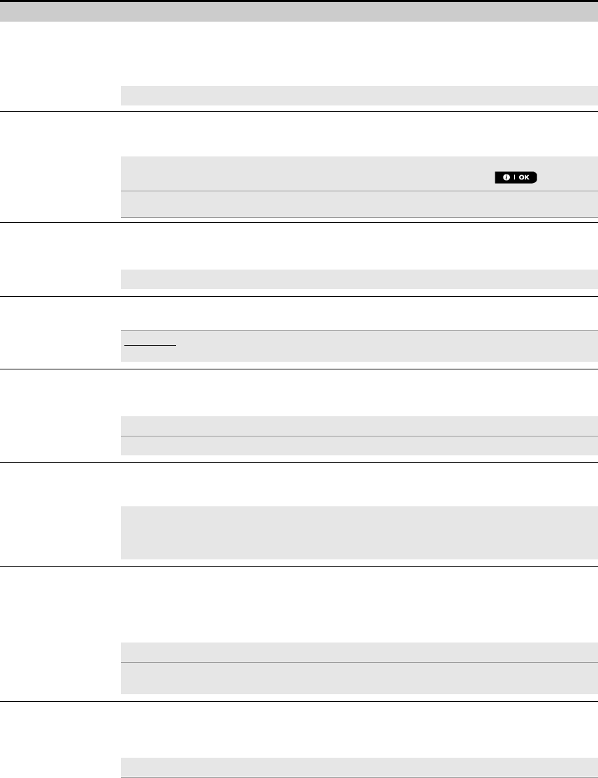
1.1 System Features
The following table lists the PowerMaster 360 features with a description of each feature and how to use it.
Feature Description How to configure and use
Visual Alarm
Verification
The PowerMaster 360 when used with Next
CAM PG2 PIR-camera detector and GPRS
communication is able to provide the
Monitoring Station with clips captured in
alarm situations. The system sends the clips
to the Monitoring Station automatically for
burglary alarms and, depending on setup,
also for fire and personal emergency alarms.
1. Setup GPRS communication: see GSM
Module Installation (section 3.4).
2. Configure camera settings: refer to the
Next CAM PG2 Installation Instructions.
3. Enable fire and personal alarm
verification: see section 4.6.5 Configuring
Motion Cameras for Video Alarm Verification.
On demand clips from
cameras
The PowerMaster 360 can provide images
from the Next CAM PG2 by demand from a
remote PowerManage server. Pictures are
taken based on a command from the
monitoring station. To protect customers'
privacy, the system can be customized to
enable the "On Demand View" only during
specific system modes (i.e. Disarm, Home &
Away) and also to a specific time window
following an alarm event.
1. Setup the On demand feature: see
section 4.6.5 Configuring Motion Cameras
for Video Alarm Verification.
2. To request and view images: refer to the
PowerManage User's Guide, Chapter 5
Viewing and Handling Events..
Easy Enrollment PowerG devices are enrolled from the control
panel’s Virtual Keypad. "Pre-enrollment" can
also be performed by entering the PowerG
device ID number and then activating the
device in the vicinity of the panel.
To enroll or pre-enroll devices: see section
4.4.2 Adding New Wireless Devices.
Device Configuration Device parameters and related system
behavior can be configured from the control
panel or from a remote location.
Each PowerG device has its own settings
which can be configured through the control
panel by entering the "DEVICE SETTINGS"
menu.
Note: The minimum configuration of the
system includes one detector.
To configure devices from the control
panel: see Chapter 4 Programming and also
the individual device's Installation
Instructions.
To configure devices from a remote
location: refer to the PowerManage User's
Guide Chapter 3 Working with Panels and to
the Remote Programmer PC software User's
Guide, Chapters 6 and 7.
1. INTRODUCTION
4 D-305735 PowerMaster 360 Installer's Guide
Diagnostics of the
control panel and
peripherals
You can test the function of all wireless
sensors deployed throughout the protected
area, to collect information about the
received signal strength from each
transmitter and to review accumulated data
after the test.
To perform diagnostics and to obtain
signal strength indication: see section 4.8
Diagnostics.
Conducting periodic
tests
The system should be tested at least once a
week and after an alarm. The periodic test
can be conducted locally or from a remote
location (with the assistance from a non-
technical person in the house).
To conduct a walk test locally: see
Chapter 5 Periodic Test.
To conduct a walk test from remote
location: refer to the Remote Programmer
PC software User's Guide, Chapter 6 Data
Details Tables.
Partitions The partitioning feature, when enabled,
divides your alarm system into distinct areas
each of which operates as an individual
alarm system. Partitioning can be used in
installations where shared security systems
are more practical, such as a home office or
warehouse building.
1. Enable partitioning: see section 4.12
Partitioning.
2. Setup partition association for each
device: see section 4.4.2 Adding New
Wireless Devices.
To understand more about partitioning:
see APPENDIX E. Working with Partitions
and APPENDIX B. in the User's Guide.
Device configuration
templates
The default parameters with which a new
device is enrolled into the system can be set
before you enroll devices. This default
template saves time on device configuration.
1. Define enrollment defaults for devices:
see section 4.4.7 Defining Configuration
Defaults for "Device Settings".
2. Enroll or pre-enroll devices: see section
4.4.2 Adding New Wireless Devices.
SirenNet - distributed
siren using Smoke
detectors
All PowerG smoke detectors are able to
function as sirens, alerting on any of 4 types of
alarm in the system: fire, gas, burglary and
flood.
Enable and configure SirenNet for each
smoke detector: refer to the SMD-426 PG2
/ SMD-427 PG2 Installation Instructions.
Reporting to Private
Users and/or
Monitoring Station by
SMS and IP
communication
The PowerMaster 360 system can be
programmed to send notifications of alarm
and other events to 4 SMS cellular phone
numbers and to report these events to the
Monitoring Station by SMS or IP
communication.
To configure notifications to Private
phones: refer to the PowerMaster 360
User's Guide, Chapter 4, section B.12
Programming Email, MMS and SMS
Reporting.
To configure reporting to the Monitoring
Station: see section 4.6.3 Configuring
Events Reporting to Monitoring Stations.
Quick installation with
link quality indication
With PowerG devices, there is no need to
consult the control panel when mounting a
wireless device, because PowerG devices
include a built-in link quality indicator.
Choosing the mounting location is a quick
and easy process.
To choose the ideal location to mount a
wireless device, see Chapter 2 Choosing the
Installation Location.
1. INTRODUCTION
D-305735 PowerMaster 360 Installer's Guide 5
Device Locator Helps you to easily identify the actual device
displayed on the LCD display.
To read more on the Device Locator: refer
to the PowerMaster 360 User's Guide,
Chapter 2, Operating the PowerMaster 360
System.
To use the device locator when bypassing
a zone or when clearing a bypassed zone:
refer to the PowerMaster 360 User's Guide,
Chapter 4, section B.1 Setting the Zone
Bypass Scheme.
To use the device locator when
conducting the periodic test: see
Chapter 5 Periodic Test or refer to the
PowerMaster 360 G2 User's Guide,
Chapter 7 Testing the System.
Guard key-safe PowerMaster is able to control a safe that
holds site keys that are accessible only to the
site's guard or Monitoring Station's guard in
the event of an alarm. Operates with the
magnetic contact device with auxiliary input
only (MC-302E PG2)
1. Configure the safe's zone type to
"Guard Zone": see section 4.4.2 Adding
New Wireless Devices.
2. Setup guard code: see section 4.3
Setting Installer Codes.
Arming Key External system may control arming and
disarming of the PowerMaster system.
Refer to the MC-302 PG2 / MC-302E PG2 /
MC-302V PG2 Installation Instructions.

2. CHOOSING THE INSTALLATION LOCATION
6 D-305735 PowerMaster 360 Installer's Guide
2. CHOOSING THE INSTALLATION LOCATION
To ensure the best possible mounting location of the PowerMaster 360 control panel, the following points should be
observed:
• The selected location should be approximately in the center of the installation site between all the transmitters,
preferably in a hidden location.
• In close proximity to an AC source
• Where there is good cellular coverage, if GSM-350 PG2 is used
• Far from sources of wireless interference, such as:
o Computers or other electronic devices, power conductors, cordless phones, light dimmers, etc.
o Large metal objects (such as metal doors or refrigerators)
Note: A distance of at least 1 meter (3 ft) is recommended.
When mounting wireless devices:
• Make sure that the signal reception level for each device is either "Strong" or "Good", but not "Poor".
• Wireless magnetic contacts should be installed in a vertical position and as high up the door or window as possible.
• Wireless PIR detectors should be installed upright at the height specified in their Installation Instructions
• Repeaters should be located high on the wall in mid-distance between the transmitters and the control panel.
WARNING! To comply with FCC and IC RF exposure compliance requirements, the control panel should be located at
a distance of at least 20 cm from all persons during normal operation. The antennas used for this product must not be
co-located or operated in conjunction with any other antenna or transmitter.
Le dispositif doit être placé à une distance d'au moins 20 cm à partir de toutes les personnes au cours de son
fonctionnement normal. Les antennes utilisées pour ce produit ne doivent pas être situés ou exploités conjointement
avec une autre antenne ou transmetteur.
3. INSTALLATION
D-305735 PowerMaster 360 Installer's Guide 7
3. INSTALLATION
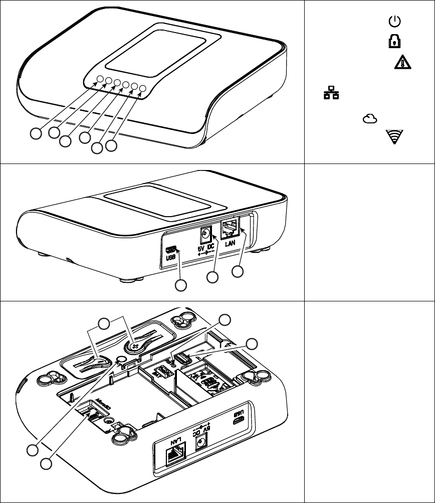
3.1 Connections and LED Indications
A. Power indication
B. Status indication
C. Trouble indication
D. Service server indication
E. Smart Home Service
Indication
F. WiFi indication
G. Micro USB connection
H. 5V DC Power connection
I. LAN connection
J. Functional pushbuttons
(for future use):
+ button - Add Visonic /
Z-Wave devices
_ button - Delete Visonic /
Z-Wave devices
K. Hole for reset button
L. Back to factory: Press for
30 sec. to restore system
parameters to factory
default parameters
M. Micro SD memory card
holder (for future use)
N. Enroll LED (for future use)
ABCDEF
HI
G
K
J
L
NM
3. INSTALLATION
8 D-305735 PowerMaster 360 Installer's Guide
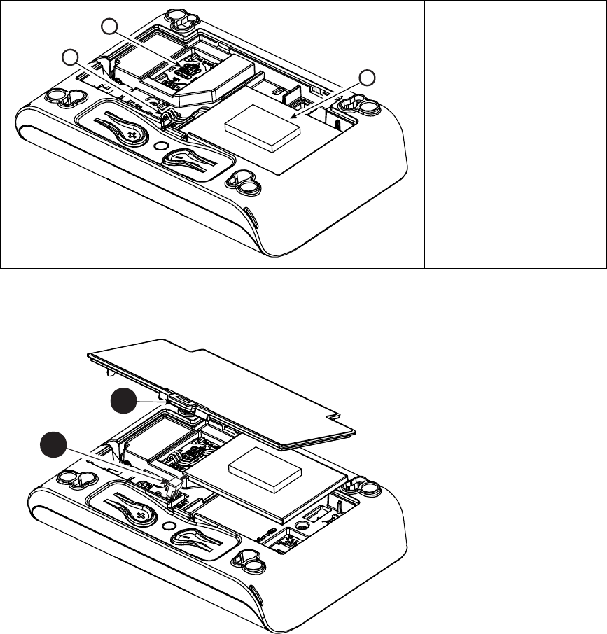
O. Battery plug socket
P. GSM Module SIM card
holder
Q. Rechargeable battery
Figure 3.1 – Connections and LED indications
3.2 Inserting the Battery
1. Press on the tab inward
and lift to remove the
battery cover.
2. Insert the battery cable
plug into the battery
socket.
3. To close the battery
cover, align the two tabs
of the battery cover with
their respective slots and
press down on the cover
in the direction shown until
a click is heard.
O
P
Q
2
1
3. INSTALLATION
D-305735 PowerMaster 360 Installer's Guide 9
Figure 3.2 – PowerMaster 360 Battery Insertion
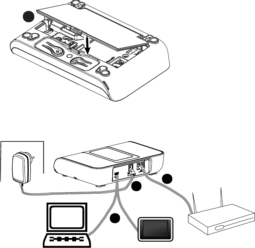
3.3 PowerManage 360 Connections
Note: If there is a GSM module in your control panel, connect first the SIM card before performing the following
procedure (see section 3.5).
1. Connect the DC power supply from the mains electrical socket to the power connection.
2. Connect the IP cable from the LAN connection to the local home-router connection.
3. To work with the Configurator, connect the micro USB cable from the micro USB connection to the PC/laptop/tablet
connection.
4. After completing the setup in the Configurator, disconnect the USB cable from the PowerMaster 360.
Note: See APPENDIX A for using the PC configurator and APPENDIX B for the VISONIConfig.
Figure 3.3 – PowerMaster 360 Panel Connections
3
2
1
3
3. INSTALLATION
10 D-305735 PowerMaster 360 Installer's Guide
3.4 GSM Connection and Configuration
The GSM modem auto detection feature enables automatic enrollment of the GSM modem into the control panel
memory. GSM modem auto detection is activated after reset (power-up or after exiting the Installer Mode menu). This
causes the PowerMaster 360 to automatically scan GSM COM ports for the presence of the GSM modem.
In the event that the GSM modem auto detection fails and the modem was previously enrolled in the control panel, the
message "Cel Remvd Cnfrm" will be displayed on the Configurator’s Virtual Keypad. This message will disappear from
the display only after the user presses the <OK> button. The modem is then considered as not enrolled and no GSM
trouble message will be displayed.
Notes:
1) A message is displayed only when the alarm system is disarmed.
2) The GSM Alarm Transmission System is designed to comply with EN 50131-1 ATS4. This was proven by testing
the signaling security requirements D2, M2, T3, S1, I2” detailed in EN 50136-1-1:1998/A2: 2008, EN 50136-2-
1:1998/A1: 2001.
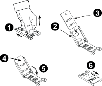
3.5 SIM Card Insertion
Insert the SIM card into the GSM module (indicated “O”
in section 3.1 above) as shown in the drawing.
1. Slide top cover.
2. Open cover
3. Align SIM card in cover (note cover orientation)
4. Slide SIM card into cover
5. Rotate cover to close
6. Lock cover to close
IMPORTANT! Do not insert or remove the SIM card
when the control panel is powered by AC power or
battery.
To configure the GSM modem, see section 4.6.2.
3.6 PowerMaster 360 Prerequisites
Connection to PowerManage requires the following ports to be open on the router. From home to internet:
• TCP ports : 8080, 5001
• UDP port: 5001
• FTP port: 21
Note: In a typical home router these ports should already be open.
The Windows 7 PC Operation System is supported for the Configurator.
3.7 Enrolling / Deleting a Z-Wave Device
Enrolling a Z-Wave Device
To enroll a device, proceed as follows.
1. Press and hold the (+) button (“J” in Figure 3.1) for 2 seconds. The red LED (“N” in Figure 3.1) blinks slowly.
2. Press the device Enroll button.
3. If Enroll is successful, the green LED blinks quickly and a happy beep is heard and then the LED turns off.
Notes:
1. To abort enrollment during this stage, press and hold the (+) or (-) buttons for 2 seconds. The LED will stop
blinking.
2. If enroll fails, the red LED lights constantly for 3 seconds and a sad beep is heard.
3. Long press on the (+) button, returns the panel to normal operation.
3. INSTALLATION
D-305735 PowerMaster 360 Installer's Guide 11
Deleting a Z-Wave Device
To delete an enrolled device, proceed as follows.
1. Press and hold the (-) button (“J” in Figure 3.1) for 2 seconds. The red LED (“N” in Figure 3.1) blinks quickly and a
happy beep is heard and then the LED turns off.
Notes:
1. To abort the procedure during this stage, press and hold the (+) or (-) buttons for 2 seconds. The LED will stop
blinking.
2. If the procedure fails, the red LED lights constantly for 3 seconds and a sad beep is heard.
3. Long press on the (-) button, returns the panel to normal operation
3.8 Panel Reset
To reset the panel, use a blunt instrument to press the Reset button (“K” in Figure 3.1), or, alternatively, exit the
Installer Mode. The Orange LED (“N” in Figure 3.1) lights constantly until Panel initialization is completed and the
PowerLink is reset. Finally, the Orange LED (“N”) turns off.
3.9 Factory Default Restore
This procedure is performed to restore system parameters to factory default parameters. Back to Factory can be
performed only when the panel is in the Disarmed state.
1. Press the Back to Factory button (“L” in Figure 3.1) for 30 seconds.
Note: During Back to Factory, the red LED (“N” in Figure 3.1) blinks.
2. If Back to Factory is successful: the green LED blinks 3 times and a happy beep is heard and then the panel
immediately initiates software reset.
Note: If the Back to Factory procedure fails, the red LED lights constantly for 3 seconds and a sad beep is heard.

4. PROGRAMMING
12 D-305735 PowerMaster 360 Installer's Guide
4. PROGRAMMING
4.1 General Guidance
This chapter explains the Installer programming (configuration) options of your PowerMaster 360 system and how to
customize its operation to your particular needs and end user requirements.
Software configuration of the alarm system is performed using the Virtual Keypad which contains the control keys,
numerical keypad and display.
The control panel includes a partition feature. Partitioning allows you to have up to three independently controllable
areas with different user codes assigned to each partition. A partition can be armed or disarmed regardless of the
status of the other partitions within the system.
The Soak Test feature allows selected zones to be tested for a pre-defined period of time. When in Soak Test mode,
activating a zone does not cause an alarm and siren and strobe are not activated. The zone activation is recorded in
the event log and is not reported to the Monitoring Station. The zone remains in Soak Test until the pre-defined period
of time for the Soak Test has elapsed without any alarm activation. The zone then automatically removes itself from
Soak Test mode and returns to normal operating mode.
Software Upgrade allows you to upgrade the software of the control panel from the remote PowerManage server.
During software upgrade, the PowerMaster 360 Virtual Keypad display will read "UPGRADING…" which is displayed
throughout the software upgrade procedure.
Note: Software Upgrade cannot be performed when the control panel is armed AWAY or there is an AC failure.
Tech Tip
:
For your convenience, we recommend programming the PowerMaster 360 on the work bench before actual installation.
Operating power may be obtained from the backup battery or from the AC power supply.
ATTENTION! FIRST SWITCH ON THE CONTROL PANEL and then INSERT BATTERIES INTO ACCESSORIES
DEVICES.
The devices "search" for the control panels to which they are enrolled for a period of only 24 hours from the time of
battery insertion.
Note: If you have switched on the control panel a long time after inserting batteries into the accessories devices: Open
and then close the cover to activate the tamper switch (where applicable), or remove the battery and then put back the
battery.
4.1.1 Navigation
The Virtual Keypad's buttons are used for navigation and configuration when programming. The following table
provides a detailed description of the function or use of each button.
Button
Definition
Navigation / Setting Function
NEXT
Use to move / scroll forward to the next menu options.
BACK
Use to move / scroll backward to the previous menu options.
OK
Use to select a menu option or to confirm a setting or action.
HOME
Use to move one level up in the menu or to return to previous setting step.
AWAY
Use to jump back to the [<OK> TO EXIT] screen to quit programming.
OFF
Use to cancel, delete, clear or erase setting, data, etc.
0 – 9
Numerical keypad used to enter numerical data when needed.
Note: The above buttons are identical in function to the corresponding buttons shown throughout the document.
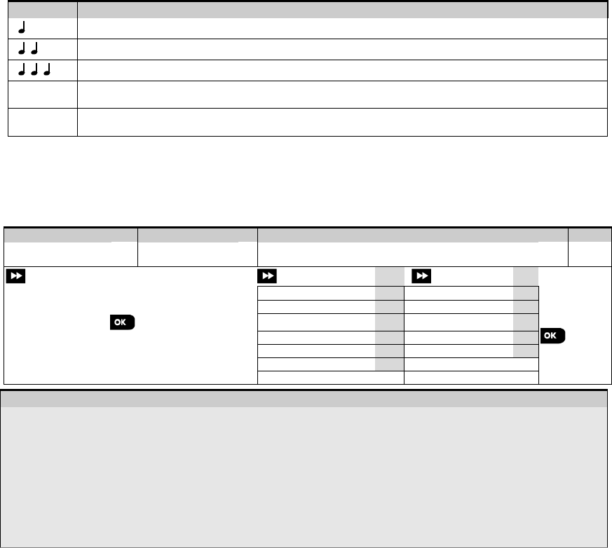
To review the options within the control panel menus and select an option, repeatedly press the Next or Back
button until the desired option is displayed (also designated as in this guide), then press the OK
button to select the desired option (also designated as in this guide). To return to the previous options repeatedly
press the Home button and to exit the programming menu press the Away button.
To simplify the procedure further, you really need two basic buttons to program the entire panel: The Next
and the OK button. The button scrolls through the options, and the button selects the option

4. PROGRAMMING
D-305735 PowerMaster 360 Installer's Guide 13
you want.
4. PROGRAMMING
14 D-305735 PowerMaster 360 Installer's Guide
4.1.2 Feedback Sounds
The sounds you will hear via the Configuration device (PC or mobile) while using and configuring the control panel are:
Sound
Definition
Single beep, heard whenever a key is pressed
Double beep, indicates automatic return to the normal operating mode (by timeout).
Three beeps, indicates a trouble event
♫
Happy Tune (- - - –––), indicates successful completion of an operation.
♫
Sad Tune (–––––), indicates a wrong move or rejection
4.2 Entering the "Installer Mode" and Selecting a Menu Option
All Installer Mode menu options are accessed via the "Installer Mode" which is usually one of the main panel menu
options.
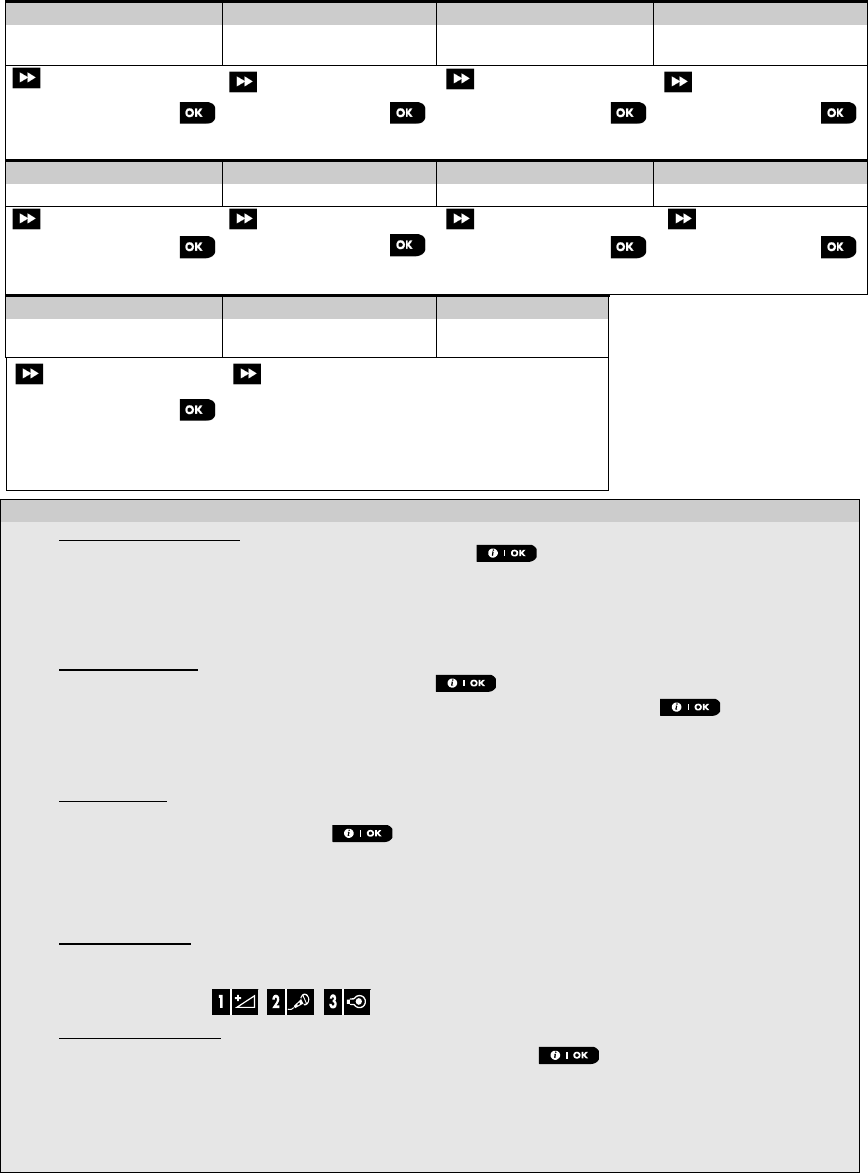
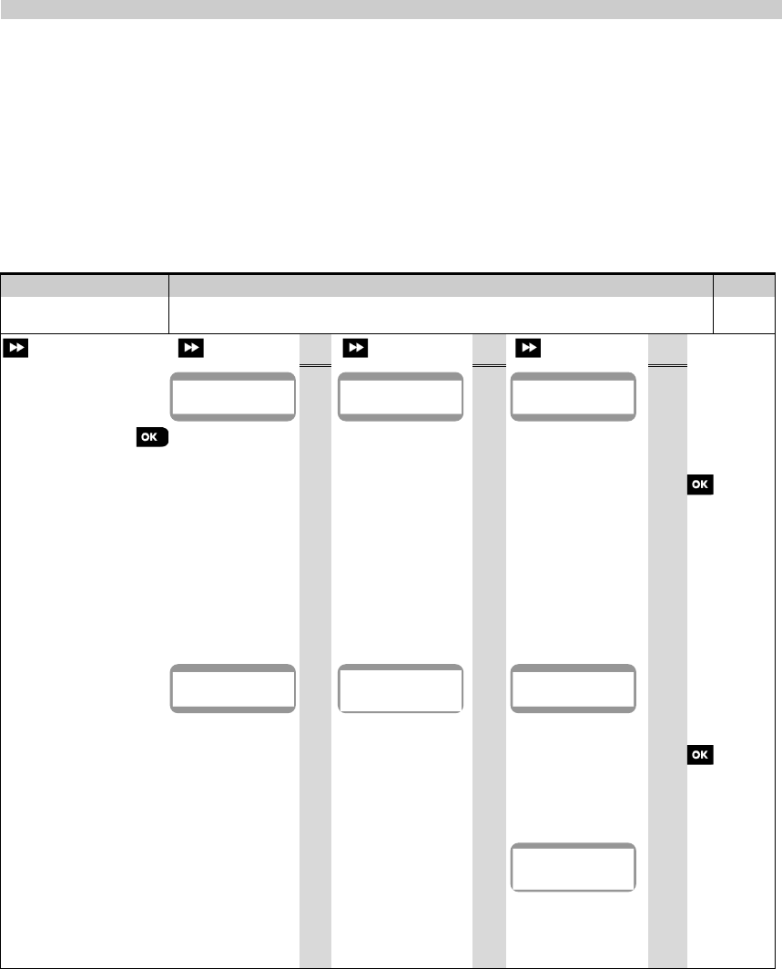
To enter the "Installer Mode" and select an Installer Mode menu option proceed as follows:
Step 1
Step 2
Step 3
Step 4
Select "INSTALLER
MODE" Option
[1]
Enter
Installer Code
[2]
Select Installer Mode menu option
[3]
See
See
READY 00:00
01:INSTALL CODES
4.3
08:USER SETTINGS
4.9
Go to
the
indicated
section
of the
selected
option
02:ZONES/DEVICES
4.4
09:FACTORY DEFLT
4.10
INSTALLER MODE
ENTER CODE:
03:CONTROL PANEL
4.5
10:SERIAL NUMBER
4.11
If the "Installer
Mode" is not shown,
refer to section 4.2.1
04:COMMUNICATION
4.6
12:PARTITIONING
4.12
06:CUSTOM NAMES
4.7
13:OPERATION MOD
4.13
07:DIAGNOSTICS
4.8
<OK> TO EXIT
- Entering the "Installer Mode" menu
[1]
You can access the "Installer Mode" only when the system is disarmed. The process described refers to the
case where "User permit" is not required. If "User permit" is required, select the "User Settings" option and
ask the Master User to enter his code and then scroll the "User Settings" menu and select the "Installer Mode"
option (last option in the menu). Continue to Step 2.
[2]
If you have not already changed your Installer code number, use the default settings: 8888 for installer & 9999 for
master installer.
If you enter an invalid installer code 5 times, the keypad will be automatically disabled for a pre-defined period of
time and the message WRONG PASSWORD will be displayed.
[3]
You have now entered the Installer Mode menu. Scroll and select the menu you wish and continue to its
corresponding section in the guide (indicated on the right side of each option).
4.2.1 Entering the "Installer Mode" if "User Permit" is enabled
In certain countries the regulations may require user permission to make changes in the configuration of the panel. To
comply with these regulations, the "Installer Mode" option can be accesses only via the "User Settings" menu. The
Master user must first enter the "User Settings" menu then scroll until the "Installer Mode" option is shown and then
the installer can continue as shown in the above table (see also [1] in Step 1 above).
To configure the panel to comply with user permission requirements - see option #91 "User Permit" in section 4.5.8.
4. PROGRAMMING
D-305735 PowerMaster 360 Installer's Guide 15
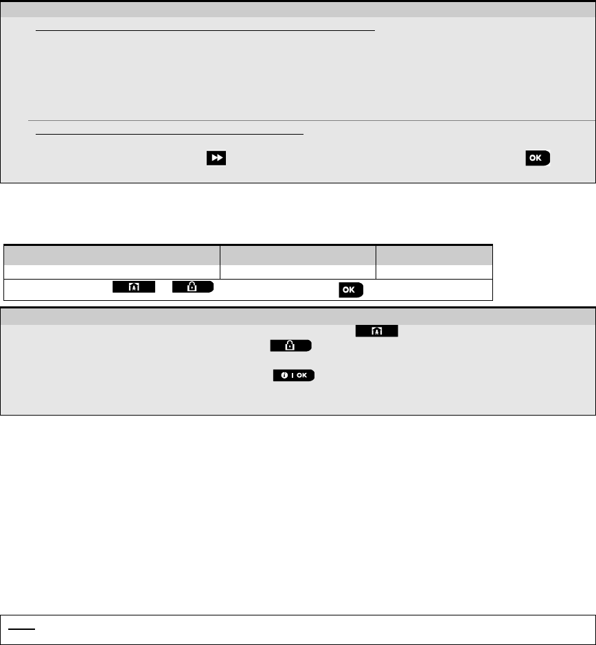
4.2.2 Selecting options
– Selecting an option from a menu
Example: To Select an Option from the "COMMUNICATION" menu:
[1]
Enter the Installer Mode menu and select the "04.COMMUNICATION" option (see section 4.2).
[2]
Select the sub-menu option you need, for example: "3: C.S. REPORTING".
[3]
Select the parameter you wish to configure for example: "11:RCVR 1 ACCOUNT"
[4] To continue, go to the section of the selected sub-menu option, for example section 4.6.3 for the
"3:C.S.REPORTING" menu, and look for the sub-menu you wish to configure (e.g. "11:RCVR 1 ACCOUNT"). After
configuring the selected parameter the display returns to step 3.
To Change the Configuration of the Selected Option:
When entering the selected option, the display shows the default (or the previously selected) setting marked with .
To change the configuration, scroll the "Options" menu and select the setting you wish and press to
confirm. When done, the display reverts to Step 3.
4.2.3 Exiting the Installer Mode
To exit the Installer Mode, proceed as follows:
Step 1
Step 2
Step 3
[1]
[2]
[3]
Any screen or
<OK> TO EXIT
READY 12:00
– Exiting the Installer Mode
[1] To exit "INSTALLER MODE", move up the menu by pressing the button repeatedly until the display
reads "<OK> TO EXIT" or preferably; press the button once which brings you immediately to the exit
screen "<OK> TO EXIT".
[2]
When the display reads "<OK> TO EXIT", press .
[3]
The system exits the “INSTALLER MODE" menu and returns to the normal disarm state while showing the
READY display.
4.3 Setting Installer Codes
The PowerMaster 360 system provides two installer permission levels with separate installer codes, as follows:
• Master Installer: The "Master Installer" is authorized to access all Installer Mode menu and sub-menu options. The
default code is: 9999 (*).
• Installer: The "Installer" is authorized to access most but not all Installer Mode menu and sub-menu options. The
default code is 8888 (*).
• Guard Code: Enables an authorized guard to only Arm Away / Disarm the control panel. The default code is 0000 (*).
The following actions can be performed only by using the Master Installer code:
• Changing the Master Installer code.
• Defining specific communication parameters – see "3:C.S REPORTING" in sections 4.6.2 and 4.6.3.
• Resetting the PowerMaster 360 parameters to the default parameters – see "09:FACTORY DEFLT" in section
4.11.
Note: Not every system includes a Master Installer code feature. In such systems, the Installer can access all Installer
Mode menu and sub-menu options the same as a Master Installer.
(*) You are expected to use the default codes only once for gaining initial access, and replace it with a secret
code known only to yourself.
4. PROGRAMMING
16 D-305735 PowerMaster 360 Installer's Guide
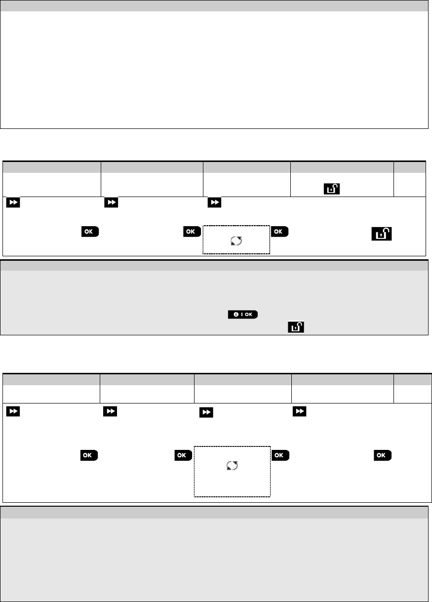
To change your Master Installer or Installer Codes proceed as follows:
Step 1
Step 2
Step 3
Step 4
Select "01:INSTALL
CODES" Option
[1]
Select Master Installer,
Installer code or Guard
code
[2]
Enter NEW Master Installer,
Installer code or Guard code
[3]
INSTALLER MODE
NEW MASTER CODE
MASTER CODE 999
to step 2
to step 2
ENTER CODE:
or
or
NEW INST. CODE
INST. CODE 888
or
or
01:INSTALL CODES
NEW GUARD CODE
GUARD CODE
000
to step 2
– Setting Installer Codes
[1]
Enter the Installer Mode menu and select the "01:INSTALL CODES" option (see section 4.2).
[2]
Select the "NEW MASTER CODE", "NEW INST. CODE" or "NEW GUARD CODE". Some panels may have
only the Installer Code and New Guard Code option.
[3] Enter the new 4-digit Code at the position of the blinking cursor and then press .
Notes:
1. Code "0000" is not valid for Master Installer or installer.
2. Inserting “0000” for the Installer will delete the Installer Code.
3. Warning! Always use different codes for the Master Installer, for the Installer and for the Users.
If the Master Installer Code is identical to the Installer code, the panel will not be able to recognize the
Master Installer. In such a case, you must change the Installer code to a different code. This will re-validate
the Master Installer code.
4.3.1 Identical Installer and Master Installer Codes
In a 2-installer code system, the non-master installer may inadvertently change his Installer Code to that of the Master
Installer Code. In this case, the panel will allow the change in order to prevent the non-master installer from realizing
the discovery of the Master Installer's Code. The next time the Master Installer enters the Installer Mode the Master
Installer will be considered as an Installer and not as a Master Installer. In such a case the Master Installer should use
one of the following solutions:
(a) Access the panel using the Remote Programmer PC software application and change the Master Installer Code to
a different code than the one programmed by the Installer.
(b) 1. Change the Installer Code to a temporary code, 2. exit the Installer Mode, 3. enter the Installer Mode again using
the Master Installer code (the Master Installer Code will now be accepted), 4. change the Master Installer code to a
different code, 5. and change the NON-Master Installer Code back again (in other words, undo the change to the
temporary code) so that the NON-Master Installer can still enter the system.
4.4 Zones / Devices
4.4.1 General Guidance & Zones/Devices Menu Options
The ZONES/DEVICES menu enables you to add new devices to the system, to configure them and to delete them, if
required.
To select an option follow the instructions below. Additional details and guidance are provided in section 4.2.
INSTALLER MODE
02:ZONES/DEVICES
MENU you wish
indicates scroll
and select
Option
Use
Section
ADD NEW DEVICES
Use to enroll and configure the device's operation according to your preference
and in case of sensors to also define their zone name (location), zone type and
chime operation.
4.4.2
DELETE DEVICES
Use to delete devices from the system and to reset their configuration.
4.4.3
MODIFY DEVICES
Use to review and/or change the device's configuration.
4.4.4
REPLACE DEVICES
Use to replace faulty devices with automatic configuration of the new device.
4.4.5
ADD TO SOAK TEST
Use to enable the Soak Test for device zones.
4.4.6
DEFINE DEFAULTS
Use to customize the defaults of the device's parameters according to your
personal preferences for each new device enrolled in the system.
4.4.7
4. PROGRAMMING
D-305735 PowerMaster 360 Installer's Guide 17
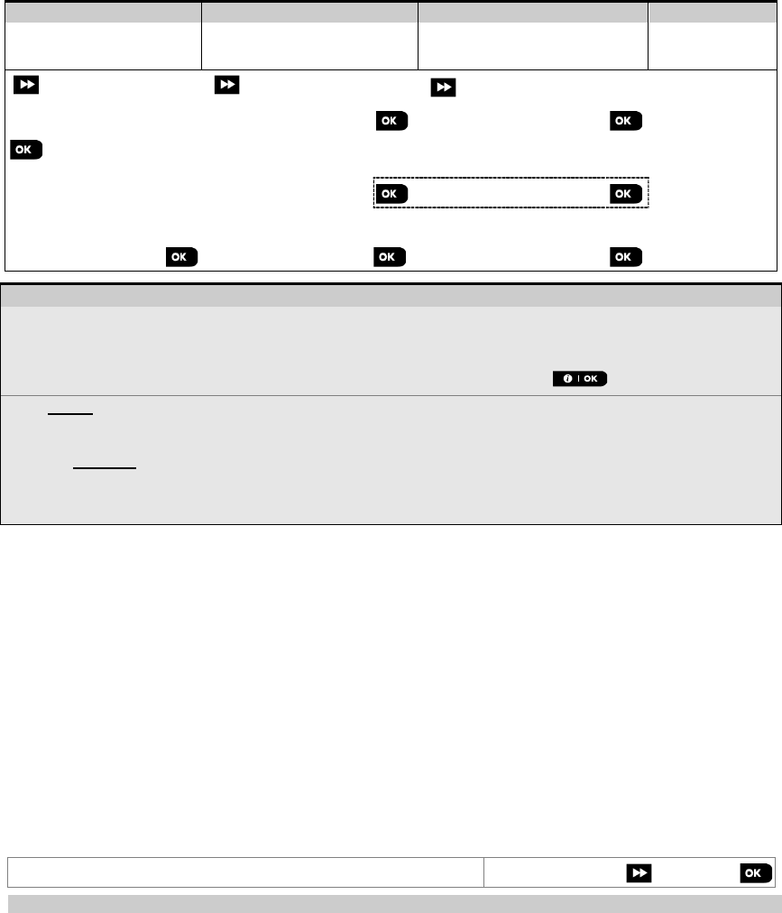
4.4.2 Adding New Wireless Devices
Part A - Enrollment
To enroll and configure a device, follow the instructions in the following chart
Step 1
Step 2
Step 3
Step 4
Select "ADD NEW
DEVICE" Option
[1]
Enroll the device or
Enter the device ID
[2]
Select a Zone number
[3]
Configure zone &
device Parameters
[4]
ADD NEW DEVICE
ENROLL NOW or
ENTR ID:XXX-XXXX
Z01:Motion Sens
ID No. 120-1254
Continue to the 2
nd
diagram in Part B below
Press the enrollment
button or enter the device
ID. Refer to the detailed
instructions below
Z10:Motion Sens
ID No. 120-1254
- Adding New Devices
[1]
Enter "INSTALLER MODE", select "02:ZONES DEVICES" (see section 4.2) and then select "ADD NEW DEVICE".
Because of encryption, PowerG devices (including Keyfobs) cannot be used on more than one system at one
time. Remember to verify panel and device compatibility.
[2] See enrollment by button or device ID below. If enrollment is successful, the display reads "DEVICE ENROLLED"
(or "ID ACCEPTED") and then shows the device details - see [3]. However, if the enrollment fails, the display will
advise you the reason for failure, for example: "ALREADY ENROLLED" or "NO FREE LOCATION".
If the enrolled device is adapted to operate as another device that the panel recognizes, the display then reads
“ADAPTED TO <OK>”.
[3]
The display shows the device details and the first available free Zone number for example: "Z01:Motion
Sensor > ID No. 120-1254" (or "K01:Keyfob / S01:Siren etc. depending on the type of the enrolled device).
Detectors can be enrolled in any zone number. To change the zone number, click the button or type in
the zone number, and then press to confirm.
[4]
Continue to Part B to configure the device – see diagram below
How to check Panel
Device compatibility
Each PowerG device bears a 7-character Customer ID printed on the device sticker in the format: FFF-M:DDD, (for
example, 868-0:012) where FFF is the frequency band and M:DDD is the variant code.
For PowerG system devices compatibility, make sure the frequency band (FFF) and the variant code (M) of the devices
match. The DDD can be ignored if the panel displays “ANY” for DDD.
Enrollment by using Device ID
The 7-digit Device ID can be used to register a device into the panel locally or from a remote location using the Remote
Programmer PC software. The enrollment by device ID is a 2 stage procedure.
In the 1st stage you register the devices' ID numbers into the panel and complete the device configuration. This can be
done from a remote location using the Remote Programmer PC software. Following the 1st stage, the PowerMaster
360 panel waits for the device to appear on the network in order to complete the enrollment.
In the 2nd stage, the enrollment is completed when the panel is in full working mode by inserting the battery into the
device, or by pressing the tamper or enrollment button on the device. This procedure is very useful for adding devices
to existing systems without the need to provide technicians with the Installer Code, or to allow access to the
programming menus.
Remember! The system will indicate a "NOT NETWORKD" trouble until the 2nd stage of all registered devices is
completed.
Note: The Soak Test on pre-enrolled zones can be activated only when the zone is fully enrolled.
Enrollment by using the Enrollment button
The panel is set to the Enrollment mode (step #2 above) and the device is enrolled using the Enroll button (refer to the
device information in the device Installation Instructions, then open the device and identify the Enroll button). For
keyfobs and keypads, use the AUX '' button. For gas detectors, insert the battery.
Press the enroll button for 2-5 seconds until the LED lights steadily and then release the button. The LED will
extinguish or may blink for a few more seconds until the enrollment is completed. If enrollment is successfully
4. PROGRAMMING
18 D-305735 PowerMaster 360 Installer's Guide
completed, the PowerMaster 360 sounds the "Happy Tune" and the Virtual Keypad momentarily shows "DEVICE
ENROLLED" and then reads the device details.
4. PROGRAMMING
D-305735 PowerMaster 360 Installer's Guide 19
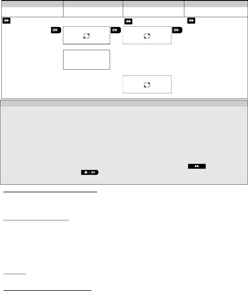
Part B - Configuration
Step 1
Step 2
Step 3
Step 4
Enter Location Menu
[1]
Select Location
(see list below)
[2] Enter Zone Type
[3]
Select Zone Type
(see list below)
[4]
➯
➯
Z10:LOCATION
Dining room
Custom 5
Z10:ZONE TYPE
1:Exit/Entry1
5. Interior
Step 5
Step 6
Step 7
Step 8
Enter Chime Menu
[5]
Select Chime option
[6]
Enter Partitions Menu
[7]
Select Partition options
[8]
➯
➯
Z10:SET CHIME chime OFF
melody-chime
Z10:PARTITIONS Z10:P1 P2 P3
Step 9
Step 10
Step 11
Enter Device Settings
Menu
[9]
Configure Device
Parameters
[10]
Continue or End
➯
Z10:DEV SETTINGS
Refer to device
datasheet in the device
Installation Instructions
for specific configuration
instructions.
To continue –
See [11]
- Configuring New Devices
Location (name) setting:
[1]
To review or change the Location (name) setting, press the button, otherwise scroll to the next option.
[2]
To change the Location name, enter the menu and select the name from the "Location List" below. You can
assign additional custom names using the "06.CUSTOM NAMES" option in the Installer Mode menu. See
section 4.7.
Note: As a shortcut, press the 2 digit serial No. of the Custom Location, which takes you directly to its menu.
Zone Type setting:
[3]
To review or change the Zone Type setting, press the button, otherwise scroll to the next option.
[4]
The zone type determines how the system handles signals sent from the device. Press and select a
suitable zone type. The list of available Zone Types and the explanation for each zone type is provided below.
Note: As a shortcut, press the 2 digit serial No. of the Zone Type shown in the Location List below, which takes
you directly to its menu.
Chime setting:
[5]
All zones are set to chime OFF by default. To configure the device to cause the panel to sound (when disarmed) a
Chime melody when tripped, press the button, otherwise scroll to the next option.
[6]
Select between "Chime OFF", "melody-chime" and "zone name-chime". In "melody chime" the control
panel sounds a chime melody when the sensor is tripped. In "zone name-chime" the control panel sounds the
zone name when the sensor is tripped. The chime operates during the Disarm mode only.
Partitions setting:
Note: The "PARTITIONS" menu appears only if Partitions is enabled in the control panel (see section 4.12).
[7]
When entering the menu, the display shows the default Partition selection (marked with ).
[8]
Use the keypad keys , , to assign partitions to the device.
Device Configuration:
[9]
To review or change the Device Configuration (settings), press the button, otherwise scroll to the next
option – see
[11].
[10]
To configure the device parameters, refer to its corresponding device datasheet in the device Installation
Instructions. The defaults of the device parameters can be also configured as explained in section 4.4.7.
[11]
After completing the configuration of the device, the wizard brings you to the "Next Step" menu with the
following 3 options:

4. PROGRAMMING
20 D-305735 PowerMaster 360 Installer's Guide
- Configuring New Devices
"NEXT Device" to enroll the next device.
"MODIFY Same Dev." reverts to Step 1 (i.e. "LOCATION") to allow you to perform additional changes to the
device, if needed.
"EXIT Enrollment" exits the enrollment procedure and returns to Step 1 bringing you back to the "ADD NEW
DEVICES" menu.
Location List
No.
Location Name
No.
Location Name
No.
Location Name
No.
Location Name
01
Attic
09
Dining Room
17
Hall
25
Utility Room*
02
Back door
10
Downstairs
18
Kitchen*
26
Yard
03
Basement
11
Emergency
19
Laundry Room*
27
Custom1∗
04
Bathroom
12
Fire
20
Living Room*
28
Custom2∗
05 Bedroom
13 Front Door
21 Master Bath
*
29
Custom3
∗
06 Child room
14 Garage
22 Master Bedr 30
Custom4∗
07
Closet
15
Garage Door
23
Office
31
Custom5∗
08
Den
16
Guest Room
24
Upstairs
∗ Can be customized by “06:CUSTOM NAMES” menu (see section 4.7)
Zone Type List
No.
Zone Type
Description
1. Exit/Entry 1 This Zone starts the exit time when the user arms the system or the entry time when the
system is armed. To configure the Exit/Entry 1 time, see sections 4.5.1 & 4.5.2 - Installer
Mode menu "03.CONTROL PANEL" options 01 and 03. (∗)
2.
Exit/Entry 2
Same as Exit / Entry 1 but with a different delay time. Used sometimes for entrances closer to
the panel. For configuring the Exit and Entry 2 delays, see sections 4.5.1 & 4.5.2 –
Installer Mode menu "03.CONTROL PANEL" options 02 and 03. (∗)
3.
Home Delay
Used for Door/Window Contacts and Motion sensors protecting entrance doors to interior
living areas where you wish to move feely when the system is armed HOME. Functions as a
"Delayed" zone when the system is armed HOME and as a "Perimeter Follower" zone when
the system is armed AWAY.
4. Inter-Follow
Similar to "Interior" zone but temporarily ignored by the alarm system during entry/exit delay
periods. Usually used for sensors protecting the route between the entrance door and the panel.
5. Interior This zone type generates an alarm only when the system is armed AWAY but not when the
system is armed HOME. Used for sensors, installed in interior areas of the premises, that
need to be protected when people are not present inside the premises.
6. Perimeter
This zone type generates an alarm when the system is armed both in AWAY and HOME
modes. Used for all sensors protecting the perimeter of the premises.
7.
Perim–Follow
Similar to "Perimeter" zone, but is temporarily ignored by the alarm system during entry/exit
delay periods. Usually used for sensors protecting the route between the entrance door and
the control panel.
8. 24h silent
This zone type is active 24 hours, even when system is DISARMED. It is used to report alarm
events from sensors or manually activated buttons to the Monitoring Station or private
telephones (as programmed) without activating the sirens.
9.
24h audible
Similar to 24hr silent zone, but also provides an audible siren alarm.
Note: This zone type is used only for burglary applications.
10. Emergency
This zone type is active 24 hours, even when the system is DISARMED. It is used to report
an emergency event and to initiate an Emergency call to the Monitoring Stations or private
telephones (as programmed).
11.
Arming Key
An Arming key zone is used to control the arming and disarming of the system.
Note: Operates with the magnetic contact device, magnetic contact device with auxiliary input
and vanishing magnetic contact device.
12.
Non-Alarm
This zone does not create an alarm and is often used for non-alarm applications. For
example, a detector used only for sounding a chime.
13.
Fire
A Fire zone is used for connecting the MC-302E (magnetic contact with hard-wired input) to a
wired smoke detector.
17.
Guard keybox
A Guard keybox zone is usually connected to a metal safe containing the physical keys
needed to enter the building. Following an alarm, the safe becomes available to a trusted
Guard who can open the Guard keybox, obtain the keys and enter the secured premises. The
4. PROGRAMMING
D-305735 PowerMaster 360 Installer's Guide 21
No.
Zone Type
Description
Guard keybox zone acts just like a 24H audible zone. The Guard keybox zone also provides
automatic audible internal and external siren alarm that is immediately reported to the
Monitoring Station (and does not depend on the Abort Time).
Notes:
1. Opening/closing the Guard keybox causes the PowerMaster 360 to signal the Monitoring
Station.
2. Operates with the magnetic contact device with auxiliary input.
18
Outdoor
A zone for outdoor areas where an activated alarm does not indicate intrusion into the house.
Note: The PIR camera / Outdoor PIR camera detector cannot be set to Outdoor Zone Type.
(∗)
These Zone types are useful mainly when you arm and disarm the system from inside the protected premises. If
you arm and disarm the system from outside (without tripping any sensor), such as using a keyfob, it is
preferred to use the other Zone Types.
4.4.3 Deleting a Device
Step 1
Step 2
Step 3
Step 4
Step 5
Select "DELETE
DEVICES" Option [1] Select the respective
device Group
[2] Select exact device
you wish to delete
[3] To delete the device:
press the key
[4]
02:ZONES DEVICES
CONTACT SENSORS
DELETE DEVICES
MOTION SENSORS
Z01:Motion Sens
ID No. 120-1254
<OFF> to delete
to
step 2
– Deleting a Device
[1]
Enter the Installer Mode Menu, select the "02.ZONES/DEVICES" option (see section 4.2) and then select the
"DELETE DEVICES" option.
[2]
Select the respective group of the device you wish to delete. For example, "MOTION SENSORS".
[3]
Scroll the Device Group, identify (by zone and/or ID number) the exact device you wish to replace, for example:
"Z01: Motion Sensor > ID No. 120-1254" and press the button.
[4]
The display prompts you "<OFF> to delete". To delete the device, press the (OFF) button.
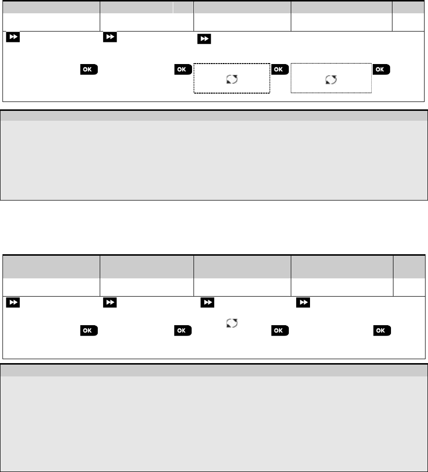
4.4.4 Modifying or Reviewing a Device
To Modify or Review the device parameters proceed as follows:
Step 1
Step 2
Step 3
Step 4
Step 5
Select "MODIFY
DEVICES" Option
[1] Select the respective
device Group
[2] Select exact device
you wish to modify
[3] Select the Parameter
you wish to modify
[4] Modify the
Parameter
02:ZONES DEVICES
CONTACT SENSORS
MODIFY SENSORS
MOTION SENSORS
Z10:Motion Camra
ID No. 140-1737
Z10:LOCATION
Z10:ZONE TYPE
Z10:SET CHIME
Z10:PARTITIONS
Z10:DEV SETTINGS
See [4]
When
done
to
step 2
– Modifying or Reviewing a Device
[1] Enter the Installer Mode menu, select the "02:ZONES/DEVICES" option (see section 4.2) and then select the
"MODIFY DEVICES" option.
[2]
Select the respective group of the device you wish to review or modify. For example, "MOTION SENSORS".
[3] Scroll the Device Group, identify (by zone and/or ID number) of the exact device you wish to modify or review, for
example: "Z10:Motion Camra > ID No. 140-1737".
[4] From here on the process is same as the configuration process that follows the enrollment of that device. To
continue, refer to Section 4.4.2 "Adding a New Wireless Device" Part B. When done, the display will show the
next device of the same type (i.e. "Motion camera").
4. PROGRAMMING
22 D-305735 PowerMaster 360 Installer's Guide
4.4.5 Replacing a Device
Use this option to replace a faulty device that is enrolled in the system with another device of the same type number
(i.e. same first 3 digit of the ID number – see section 4.4.2.A) while keeping the same configuration of the original
device. There is no need to delete the faulty device or to reconfigure the new device. Once enrolled, the new device will
be configured automatically to the same configuration of the faulty (replaced) device.
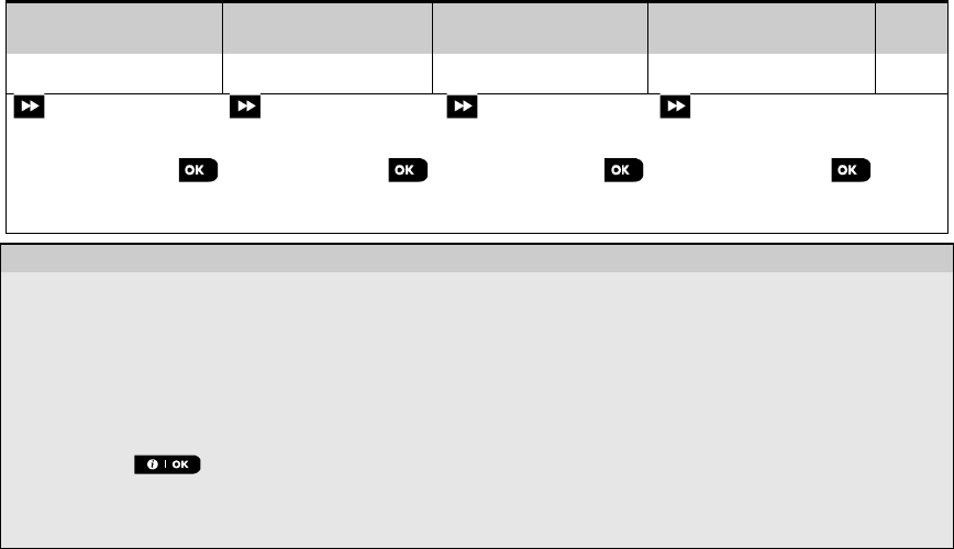
To Replace, a device proceed as follows:
Step 1
Step 2
Step 3
Step 4
Step 5
Select "REPLACE
DEVICES" Option
[1] Select the respective
device Group
[2] Select exact device
you wish to replace
[3] Enroll the new device [4]
02:ZONES/DEVICES
CONTACT SENSORS
REPLACE DEVICES
KEYFOBS
K03:Keyfob
ID No. 300-0307
ENROLL NOW or
ENTR ID:300-XXXX
See
[4].
– Replacing a Device
[1]
Enter the Installer Mode menu, select the "02:ZONES/DEVICES" option (see section 4.2) and then select the
"REPLACE DEVICES" option.
[2]
Select the respective group of the device you wish to replace. For example, "KEYFOBS".
[3]
Scroll the Device Group, identify (by zone and/or ID number) the exact device you wish to replace, for example:
"K03: Keyfob > ID No. 300-0307".
If you try enrolling a new device of a different type than the replaced device, the PowerMaster 360 will reject the
new device and the Virtual Keypad display will read "WRONG DEV.TYPE".
When done, the Virtual Keypad display shows the device details of the new device.
4.4.6 Configuring Soak Test Mode
This option enables you to enter device zones into Soak Test mode.
To Enable the Soak Test proceed as follows:
Step 1 Step 2 Step 3 Step 4 Step 5
Select "ADD TO
SOAK TEST" Option [1] Select the respective
device Group
[2] Select device zone
number
[3] Select to enable or
disable the Soak Test
[4] [5]
02:ZONES/DEVICES
CONTACT SENSORS
Z09:Motion Sens
ID No. 120-2468
ADD TO SOAK TEST
MOTION SENSORS
Disable test
Enable test
See
[5]
to
Step 3
– Enabling Soak Test mode
[1]
Enter the Installer Mode menu, select the "02.ZONES/DEVICES" option (see section 4.2) and then select the "ADD
TO SOAK TEST" option.
[2]
Select the respective Group of the device you wish to add the Soak Test. For example, "MOTION SENSORS".
[3]
Scroll to select the specific device zone number.
[4]
Select between “Disable test” (default) or “Enable test”.
[5]
If set to “Enable Test” you must set the duration of the Soak Test before the Soak Test will start (see section
4.5.8). You can stop the test for the relevant zone by changing the setting to "Disable test" at any time during the
testing period. All Soak test zones will be reset to start a new test upon occurrence of one of the following:
1) Power up of the system; 2) Setup of Factory Default; 3) Change in system Soak Time.
4. PROGRAMMING
D-305735 PowerMaster 360 Installer's Guide 23
4.4.7 Defining Configuration Defaults for "Device Settings"
PowerMaster 360 enables you to define the Default Parameters used during enrollment and to change them
whenever you wish so that new devices enrolled into the system will be configured automatically with these default
parameters without the need to modify the configuration of each new enrolled device. You can use a certain set of
defaults for certain group of devices and then change the defaults for another group.
IMPORTANT! Devices that were already enrolled in the PowerMaster 360 system before the defaults have been
changed will not be affected by the new default settings.
To Define the Default parameters of a device Group proceed as follows:
Step 1 Step 2 Step 3 Step 4 Step 5
Select "DEFINE
DEFAULTS" Option
[1] Select the respective
device Group
[2] Select the Default
Parameter
[3] Select the new
Default Setting
[4] [5]
02:ZONES/DEVICES
CONTACT SENSORS
DEFINE DEFAULTS
MOTION SENSORS
Alarm LED
Event Counter
Disarm Activity
Low
High
See
[5]
to
Step 3
– Changing Defaults
[1]
Enter the Installer Mode menu, select the "02.ZONES/DEVICES" option (see section 4.2) and then select the
"DEFINE DEFAULTS" option.
[2]
Select the respective Group of the device you wish to define its defaults. For example, "MOTION SENSORS".
[3]
Scroll the parameter list of the Device Group and select the Default Parameter you wish to change, for example:
"Event Counter". The list combines the parameters of all devices in the group, for example, the parameters of all
types of Motion sensors.
[4]
In the example, the existing default setting of the "Event Counter" for enrolled motion sensors was
"Low Sensitivity" (marked with ) . To change it to "High", scroll the menu until the display shows "High" and
press the button. The new default for the Event Counter parameter setting of Motion Sensors enrolled
from now on will be "High".
[5]
The new default does not affect motions sensors that were already enrolled before the change was made but only
new motion sensors that will be enrolled in the PowerMaster 360 after the change is performed.
4.4.8 Updating Devices after Exiting Installer Mode
When exiting the "Installer mode", the PowerMaster 360 panel communicates with all devices in the system and
updates them with the changes that have been performed in their "Device Settings" configuration. During the updating
period, the display indicates "DEV UPDATING 018" where the number (for example, 018) is a countdown of the
remaining number of devices yet to be updated.
4. PROGRAMMING
24 D-305735 PowerMaster 360 Installer's Guide
4.5 Control Panel
4.5.1 General Guidance – "Control Panel" Flow-Chart & Menu Options
The "CONTROL PANEL" menu enables you to configure and customize the operation of the control panel. The
"CONTROL PANEL" menu provides you with configurable parameters divided into several groups, each dealing with
certain aspects of the system operations as follows (see detailed list in Step 2 of the chart below):
Group
Description of Group Features and Parameters
Section
Arming/Disarming
and Exit/Entry
Procedures
Contains configurable features and parameters related to Arming and Disarming of the
system and the Exit and Entry procedures. 4.5.2
Zone Behavior
Contains configurable features and parameters related to the functionality of the Zones.
4.5.3
Alarms &
Troubles
Contains configurable features and parameters related to initiating, canceling and
reporting of Alarm and Trouble events.
4.5.4
Sirens
Contains configurable features and parameters common to all sirens in the system.
4.5.5
User Interface
Contains configurable features and parameters related to the functionality of the panel's
audible and visual indications.
4.5.6
Jamming &
Supervision Contains configurable features and parameters related to detecting and reporting of RF
Jamming and device Supervision (missing device) events.
4.5.7
Miscellaneous
Contains a variety of other configurable features and parameters related to the system.
4.5.8
To enter the "03.CONTROL PANEL" menu and to select and configure an option, proceed as follows:
Step 1 Step 2 Step 3
Select "CONTROL PANEL"
option Select the "Control Panel" Parameter you wish to configure Configure
option
See
See
See
INSTALLER MODE
4.5.2
4.5.4
4.5.6
03.CONTROL PANEL
01:ENTRY DELAY1
31:PANIC ALARM
53:MEMORY PROMPT
Go to the
indicated
group
section of
the
selected
option
02:ENTRY DELAY2
32:DURESS ALARM
54:LOW-BAT ACK
03:EXIT DELAY
33:INACTIVE ALRT
56:SCREEN SAVER
04:EXIT MODE
34:TAMPER ALARM
05:QUICK ARM
35:AC FAIL REPRT
06:BYPASS ARM
36:CONFIRM ALARM
07:LATCHKEY ARM
37:ABORT TIME
08:DISARM OPTION
38:CANCEL ALARM
09:ARMING KEY
39:ALARM RESET
40:ABORT FIRE T.
4.5.3
4.5.5
4.5.7
21:SWINGER STOP
61:JAM DETECT
When
done
to
Step 2
22:CROSS ZONING
44:SIREN TIME
62:MISSING REPRT
45:STROBE TIME
63:NOT READY
64:MISS/JAM ALRM
65:SMOK FAST MIS
4.5.8
91:USER PERMIT
93:SOAK PERIOD
Arming &
Disarming
Alarms &
Troubles
User
Interface
Zone
Behavior
Sirens Jamming and
Supervision
Miscellaneous

4. PROGRAMMING
D-305735 PowerMaster 360 Installer's Guide 25
4.5.2 Configuring Arming/Disarming and Exit/Entry Procedures
The following table provides you with a detailed description of each option and its configuration settings. To select an
option and change its configuration – refer to section 4.5.1.
Option
Configuration Instructions
01:ENTRY DELAY1
02:ENTRY DELAY2 Two different entry delays allow the user to enter the protected site (while the system is in the
armed state) via dedicated exit/entry doors and routes without causing an alarm.
Following entry, the user must disarm the control panel before the entry delay expires. Slow-
rate warning beeps start sounding via the Configuration device (PC or mobile) once the door is
opened, until the last 10 seconds of the delay, during which the beeping rate increases. The
"ENTRY DELAY 1" and "ENTRY DELAY 2" options allow you to program the time length of
these delays.
Options: 00 seconds; 15 seconds (default for entry delay 2); 30 seconds (default for entry
delay 1); 45 seconds; 60 seconds; 3 minutes and 4 minutes.
Notes:
1. In some PowerMaster 360 variants, these menus are displayed in the Operation
Mode only (see section 4.13).
2. To comply with EN requirements, the entry delay must not exceed 45 sec.
03:EXIT DELAY This option allows programming the time length of the exit delay. An exit delay allows the user
to arm the system and leave the protected site via specific routes and exit/entry doors without
causing an alarm. Slow-rate warning beeps start sounding via the Configuration device (PC or
mobile) once the arming command has been given, until the last 10 seconds of the delay,
during which the beeping rate increases.
Options: 30 seconds; 60 seconds (default); 90 seconds; 120 seconds, 3 minutes and
4 minutes.
04:EXIT MODE The "Exit Delay" time can be further adjusted according to your preferred exit route. The control
panel provides you with the following "Exit Mode" options:
A: "normal" - The exit delay is exactly as defined.
B: “restrt+arm home” - Exit delay restarts when the door is reopened during exit delay. If no
door was opened during exit delay "AWAY", the control panel will be armed "HOME".
C: "restart>reentry" - The exit delay restarts when the door is reopened during exit delay. The
restart occurs once only. Restarting the exit delay is helpful if the user re-enters
immediately after going out to retrieve an item that he left behind.
D: "end by exit" - The exit delay expires (ends) automatically when the exit door is closed
even if the defined exit delay time was not completed.
Options: normal (default); restrt+arm home; restart>reentry and end by exit.
Note: In some PowerMaster 360 variants, this menu is displayed in the Operation Mode only
(see section 4.13).
05:QUICK ARM Define whether or not the user will be allowed to perform quick arming or not. Once quick
arming is permitted, the control panel does not request a user code before it arms the system.
Options: OFF (default) and ON (default in USA).
06:BYPASS ARM
Define whether or not the user will be allowed to manually bypass individual zones, or allow
the system to perform automatic bypassing of open zones during the exit delay (i.e.
"force arm"). If a zone is open and "forced arming" is not permitted, the system cannot be
armed and “NOT READY” is displayed. If "no bypass" is selected, neither manual bypassing
nor force arming is allowed which means that all zones must be secured before arming.
Options: no bypass (default); force arm and manual bypass (default in USA).
Notes:
1. To comply with EN requirements, "manual bypass" must be selected.
2. The option "force arm" is not applicable in the UK.
3. A zone in Soak Test mode that is configured as bypass will trigger a test fail event if
the system detects a potential alarm event.
4. There is no limit of reported events when a bypass zone is in Soak Test mode.
07:LATCHKEY ARM
When "ON", a “latchkey” message will be reported by SMS message to users (see Note) upon
disarming by a “latchkey user” (users 5-8 or keyfob transmitters 5-8). This mode is useful when
parents at work want to be informed of a child’s return from school.
Options: OFF (default) and ON.
Note: To enable the reporting, you must configure the system to report "alrt" events to Private
users (Latchkey belongs to the "alerts" group of events). Refer to section 4.6.4 "REPORTED
EVENTS" option in both "
VOICE REPORT
" & "
SMS REPORT
" menus.

4. PROGRAMMING
26 D-305735 PowerMaster 360 Installer's Guide
Option
Configuration Instructions
08:DISARM OPTION
Certain regulations require that when the system is armed in AWAY mode, it may not be
disarmed from the outside of the house (such as by keyfobs) before entering the protected
premises and activating an "Entry Delay" zone. To answer this requirement, the PowerMaster
360 provides you with the following configurable options to disarm the system:
A: At "any time" (default), the system can be disarmed at all times from all devices.
B: During entry delay, the system can be disarmed only using keyfob or prox operated devices
("on entry wrless").
C: During entry delay by code, the system can be disarmed only using the Configuration device
(PC or mobile) ("entry + away kp.").
D: During entry delay, the system can be disarmed using keyfobs or by code using the
Configuration device (PC or mobile) ("on entry all.").
Note:
In some PowerMaster 360 variants, this menu is displayed in the Operation Mode only
(see section 4.13).
09:ARMING KEY
Determine that, when activated, the Arming Key will arm AWAY or HOME.
Options: arm AWAY (default) and arm HOME.
4.5.3 Configuring Zones Functionality
The following table provides you with a detailed description of each option and its configuration settings. To select an
option and change its configuration – refer to section 4.5.1.
Option Configuration Instructions
21:SWINGER STOP Define the number of times a zone is allowed to initiate an alarm within a single
arming/disarming period (including tamper & power failure events of detectors, etc.). If the
number of alarms from a specific zone exceeds the programmed number, the control panel
automatically bypasses the zone to prevent recurrent siren noise and excessive reporting to the
Monitoring Station. The zone will be reactivated upon disarming, or 8 hours after having been
bypassed (if the system remains armed).
Options:
after 1 alarm
(default);
after 2 alarms
(default in USA);
after 3 alarms
and
no stop
.
Note:
When a detector is in Soak Test1 mode and also set to bypass, Swinger Stop will not
prevent the sending of events. This may result in excessive reporting of Soak Fail
events.
22:CROSS ZONING Define whether cross zoning will be active "ON" or inactive "OFF" (default). Cross zoning is a
method used to counteract false alarms - an alarm will be initiated only when two adjacent
zones (zone couples) are violated within a 30-second time window.
This feature is active only when the system is armed AWAY and only with respect to the
following zone couples: 10+11, 12+13, 14+15.
Notes:
1. If one of the two crossed zones is bypassed (see Section 4.5.2), the remaining
zone will function independently.
2. It is recommended that crossed zones will be only zones used for detection of
burglary i.e. "Zone Types": Entry/ Exit, Interior, Perimeter and Perimeter follower.
3.
If a cross zone is in Soak Test mode, then each zone of this zone couple functions
independently.
Important! Do not define "cross zoning" to any other zone types such as Fire,
Emergency, 24h audible, 24h silent etc.
4. PROGRAMMING
D-305735 PowerMaster 360 Installer's Guide 27
4.5.4 Configuring Alarms & Troubles
The following table provides you with a detailed description of each option and its configuration settings. To select an
option and change its configuration – refer to section 4.5.1.
Option Configuration Instructions
31:PANIC ALARM Define whether or not the user will be allowed to initiate a Panic Alarm from keypads (by
simultaneous pressing the two "Panic Buttons") or keyfobs (by simultaneous pressing the
"Away" + "Home" buttons) and whether the alarm will be "silent" (i.e. only reporting of the
event) or also audible (i.e. the sirens will also sound).
Options: audible (default); silent and disabled.
32:DURESS ALARM
(not applicable in UK)
A duress (ambush) alarm message can be sent to the Monitoring Station if the user is forced to
disarm the system under violence or menace. To initiate a duress message, the user must
disarm the system using a duress code (2580 by default).
To change the code, enter the new 4-digit of the new Duress code at the position of the
blinking cursor or enter 0000 to disable the duress function and then press .
Notes: The system does not allow programming a duress code identical to an existing user
code.
33:INACTIVE ALRT
Previously known as
"NOT ACTIVE"
If no sensor detects movement in interior zones at least once within the defined time window,
an “inactive alert" event is initiated.
Define the
time window
for monitoring the
lack of motion
.
Options:
disabled
(default);
after
:
3/6/12/24/48/72 hours
34:TAMPER ALARM Define whether the Tamper switch protection of all zones and other peripheral devices (except
the control panel) are "active" (default) or "not active".
Warning!: If you select "
not active
", be aware that no alarm or report will be initiated in case
of tampering with any of the system peripheral devices.
35:AC FAIL REPRT To avoid nuisance reporting in case of short interruptions in the house of AC power, the
system reports an AC Fail message only if the AC power does not resume within a pre-
determined time delay.
Options:
after 5 minute
(default)
, after 30 minute
,
after 60 minute
or
after 3 hours.
Note:To comply with EN requirements, the time delay must not exceed 60 min.
36:CONFIRM ALARM
Previously known as
"CONFIRM TIME"
If two successive alarm events occur within a specific time window, the system can be
configured to report the second alarm event as a "confirmed alarm" (see section 4.6.3 option
61). You can activate this feature and set the respective time window.
Options: disable (default in USA); in 30/45/60 (default)/90 minutes
Note: In some PowerMaster 360 variants, this menu is displayed in the Operation Mode only
(see section 4.13).
37:ABORT TIME The PowerMaster 360 can be configured to provide a delay before reporting an alarm to the
Monitoring Station (not applicable to alarms from 24H SILENT and EMERGENCY zones).
During this delay period, the siren sounds but the alarm is not reported. If the user disarms the
system within the delay time, the alarm is aborted. You can activate the feature and select the
"Abort Time" interval.
Options: in 00 (default in USA)/15/30 (default)/45/60 seconds; in 2/3/4 minutes
Note: In some PowerMaster 360 variants, this menu is displayed in the Operation Mode only
(see section 4.13).
38:CANCEL ALARM
Previously known as
"ALARM CANCEL"
The PowerMaster 360 can be configured to provide a ”Cancel Alarm” time window that starts
upon reporting an alarm to the Monitoring Station. If the user disarms the system within that
"cancel alarm" time, a “cancel alarm” message is sent to the Monitoring Station indicating that
the alarm was canceled by the user.
Options: not active (default in USA); in 1/5 (default)/15/60 minute(s) and in 4 hours.

4. PROGRAMMING
28 D-305735 PowerMaster 360 Installer's Guide
Option
Configuration Instructions
Notes:
1. In some PowerMaster 360 variants, this menu is displayed in the Operation Mode only (see
section 4.13).
2. Since the Soak Test zone does not report an alarm event to the Monitoring Station, the
PowerMaster 360 will not send a “cancel alarm” message to the Monitoring Station even if
disarmed within the Cancel Alarm period.
39:ALARM RESET
Previously known as
"RESET OPTION"
The PowerMaster 360 provides you with the following configurable options for resetting the
alarm condition and rearming the system:
By the user as usual - by user (default). By the engineer (installer) by entering and exiting the
"Installer Mode", by entering and exiting the Event Log using the Installer Code or by accessing
the system remotely via the PowerManage server using the Installer Code (by engineer). For
accessing the system via the PowerManage server, see the PowerManage User's Guide.
Note: This feature is not applicable in the USA.
40:ABORT FIRE T. Select the length of time allowed by the system to abort a Fire alarm. The PowerMaster 360 is
able to provide an “abort interval” that starts upon detection of a Fire event. During this interval,
the buzzer sounds a warning but the siren remains inactive and the alarm is not reported. If the
user disarms the system within the allowed abort interval, the alarm is aborted.
Options:
in 00
(default)/
30
/
60
/
90 seconds
4.5.5 Configuring Sirens Functionality
The following table provides you with a detailed description of each option and its configuration settings. To select an
option and change its configuration – refer to section 4.5.1.
Option Configuration Instructions
44:SIREN TIME
Previously known as
"BELL TIME"
Define the period of time the sirens will sound upon alarm.
Options: 1/3/4 (default)/8/10/15/20 minute(s).
Notes:
1. To comply with EN requirements, the "Siren Time" must not exceed 15 minutes.
2. For Canada, the "Siren Time" must be set to 8 minutes.
45:STROBE TIME Define the length of time the strobe light will flash upon alarm.
Options: 5/10/20 (default)/40/60 minutes
.
4.5.6 Configuring Audible & Visual User Interface
The following table provides you with a detailed description of each option and its configuration settings. To select an
option and change its configuration – refer to section 4.5.1.
Option Configuration Instructions
53:MEMORY PROMPT
Define whether or not the user will receive "Memory" indication on the Virtual Keypad that an
alarm has been activated. By pressing the button in standby mode, you can view
details of the alarm memory.
Options: ON (default) and OFF.
54:LOW-BAT ACK You can activate or deactivate the "Low Battery Acknowledge" requirement from the user whose
keyfob's battery is low. For further information, see PowerMaster 360 User's Guide Chapter 6.
Options: OFF (default) – acknowledge not needed; ON – acknowledge required.
56:SCREEN SAVER
With Partition
disabled
The Screen Saver option (when activated) replaces the status display on the virtual keypad
with “PowerMaster 360” display if no key is pressed during more than 30 seconds.
You can activate the Screen Saver and determine whether the status display will resume
following any key press (refresh by Key) or by entering a code (refresh by Code). If refresh
by Key is selected, the first pressing of any key (except Fire and Emergency) will produce the
status display and the second press will perform the key function. For further information, see
the User's Guide, Chapter 1, "Screen Saver Mode".
Options: OFF (default); refresh by Code and refresh by Key.

4. PROGRAMMING
D-305735 PowerMaster 360 Installer's Guide 29
Option
Configuration Instructions
Notes:
1. To comply with EN requirements, "refresh by code" must be selected.
2. For Fire and Emergency keys, the first key press will produce the status display and will also
perform the Fire/Emergency function.
56:SCREEN SAVER
With Partition enabled
Certain regulations require that the system status display will not be exposed to unauthorized
persons. The Screen Saver option (when activated) replaces the system status indication on
the Virtual Keypad with idle text if no key is pressed during more than 30 seconds.
You can activate the Screen Saver option and determine whether the status display will resume
following any key press (Text - by Key) or by entering a code (Text - by Code). If Text by Key
is selected, the first pressing of any key (except Fire and Emergency) will produce the status
display and the second press will perform the key function. Regarding the Fire and Emergency
keys, the first key press will produce the status display and will also perform the
Fire/Emergency function.
You can also determine that if no key is pressed during more than 30 seconds the date and time
will appear on the display. You can determine that normal display will return after pressing the
button followed by entering user code (Clock - by Code) or after pressing any key (Clock
- by Key). For further information, see the User's Guide, Chapter 1, "Screen Saver Mode".
Options: OFF (default); Text - by code; Text - by Key; Clock - by Code; Clock - by Key.
Note:
1. To comply with EN requirements, "refresh by code" must be selected.
2. For Fire and Emergency keys, the first key press will produce the status display and will also
perform the Fire/Emergency function.
4.5.7 Configuring Jamming and Supervision (Missing device)
The following table provides you with a detailed description of each option and its Options. To select an option and
change its setting (configuration) – refer to section 4.5.1.
Option Configuration Instructions
61:JAM DETECT Define whether jamming (continuous interfering transmissions on the radio network) will be
detected and reported or not. If any of the jam detection options is selected, the system will not
allow arming under jamming conditions. The PowerMaster 360 provides several jam detect
and reporting options to comply with the following standards:
Note: Jamming is identified by the message "system jammed" displayed on the Virtual
Keypad.
Option
Standard
Detection and Reporting occurs when:
UL 20/20
USA
There is continuous 20 seconds of jamming
EN 30/60
Europe
There is an accumulated 30 seconds of jamming within 60 sec.
Class 6
(30/60)
British
Standard
Like EN (30/60) but the event will be reported only if the jamming
duration exceeds 5 minutes.
disabled
(default)
No jamming detection and reporting.
Notes:
To comply with EN requirements, "EN 30/60" must be selected.
To comply with UK Class-6 requirements, "class 6 (30/60)" must be selected.
62:MISSING REPRT
Previously known as
"SUPERVISION"
Define the time window for reception of supervision (keep alive) signals from the various
wireless peripheral devices. If any device does not report at least once within the selected time
window, a “MISSING” alert is initiated.
Options: after 1/2/4/8/12 (default) hour(s); and disabled.
Note: To comply with EN requirements, 1 hour or 2 hours must be selected.
63:NOT READY
Define that in case of a supervision problem (i.e. a device is "missing" - see "62: MISSING
REPRT") whether the system will continue to operate as normal or the system status will
become "Not Ready" (
upon missing
) for as long as the "Missing" trouble exists.
Options:
normal
(default) and
if missing dev.

4. PROGRAMMING
30 D-305735 PowerMaster 360 Installer's Guide
64:MISS/JAM ALRM
Previously known as
"BELL/REP.OPT"
"EN/UL standards" require that if a supervision (missing) or jamming trouble occurs during
AWAY arming, the siren will sound and the event will be reported as a tamper event.
Define whether the system will behave according to EN standard or as normal (default).
Note: To comply with EN requirements "EN standard" must be selected.
65:SMOK FAST MIS
Determine that If the smoke detector does not report at least once within a time window of 200
seconds, a “MISSING” alert is initiated.
Options: Disabled (default) and Enabled.
4.5.8 Configuring Miscellaneous Features
The following table provides you with a detailed description of each option and its configuration settings. To select an
option and change its configuration – refer to section 4.5.1.
Option Configuration Instructions
91:USER PERMIT User Permission enables you to determine whether access to the INSTALLER MODE requires
the user's permission or not. If you select enabled, the installer will be able to access the system
only through the user menu after the user code has been entered (see section 4.2).
Options: disable (default) or enable (default in UK).
Note: To comply with EN requirements, "Enable" must be selected.
93:SOAK PERIOD
Define the period of time for the Soak Test.
Options: Disable (default), 7 days, 14 days or 21 days.
Notes:
1. If set to one of the above pre-defined period of times, to be operational Soak Test mode must
also be set to “Enable Test” from the “02:ZONES/DEVICES” menu (see Section 4.4.6).
2. If a change is made to the period of time of the Soak Test while the zone is currently being
tested, this will restart the Soak Test.
3. The start of the Soak Test period is defined in the factory from 9 AM (09:00).
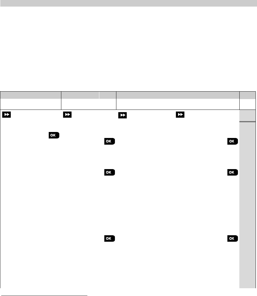
4. PROGRAMMING
D-305735 PowerMaster 360 Installer's Guide 31
4.6 Communication
4.6.1 General Guidance – "Communication" Flow-Chart & Menu Options
The COMMUNICATION menu enables you to configure and customize the communication and reporting of alarm,
troubles and other system events for monitoring companies or private users according to your local requirements and
personal preferences. PowerMaster 360 offers a variety of communication means including Cellular GSM, GPRS,
EMAIL, MMS or SMS and IP via broadband internet connection.
The "04.COMMUNICATION" menu contains several sub-menu options, each covering a group of configurable features
and parameters related to the communication and reporting as follows (see detailed list in Step 3 of the chart below):
Option
Description of Option Features and Parameters
Section
2:GSM/GPRS/SMS
Contains configurable features and parameters related to the Cellular connection
of the PowerMaster 360 system.
4.6.2
3:C.S. REPORTING
Contains configurable features and parameters related to Reporting of event
messages to Monitoring Stations via cellular or IP broadband communication.
4.6.3
4:PRIVATE REPORT
Contains configurable features and parameters related to Reporting event
messages to Private Users via email, MMS or SMS.
4.6.4
5:MOTION CAMERA
Contains configurable features and parameters related to Motion Cameras for
Video Alarm Verification.
4.6.5
6:UP/DOWNLOAD
Contains configurable connection information, access permission and security
codes related to the Upload/Download procedures via GPRS.
4.6.6
7:BROADBAND
1
Contains DHCP Client settings, enables to enter LAN parameters, to reset
broadband module and to enter LAN parameters.
4.6.7
To enter the "04.COMMUNICATION" menu and to select and configure an option, proceed as follows:
Step 1
Step 2
Step 3 Step 4
Select "COMMUNICATION" Select Communication
Sub-menu option
Select the "Communication" Parameter you wish to configure
See
INSTALLER MODE
04.COMMUNICATION
2:GSM/GPRS/SMS
GPRS PASSWORD
4.6.2
SMS REPORT
NETWORK ROAMING
GPRS APN
GPRS ALWAYS ON
GPRS USERNAME
GSM KEEP ALIVE
SIM PIN CODE
TRANS. PROTOCOL
3:C.S. REPORTING
01:REPORT EVENTS
4.6.3
02:1st RPRT CHAN
47:GSM RETRIES
() These options
are available only to
the "Master Installer"
05:DUAL REPORT
48:BB IP RETRIES
11:RCVR1 ACCOUNT
51: AUTO-TST LOOP
12:RCVR2 ACCOUNT
52:AUTO-TST TIME
21:IP RCVR 1
53:COM.FAIL RPRT
22:IP RCVR 2
→GSM/GPRS FAIL
26:SMS RCVR 1
61:RPRT CNF ALRM
27:SMS RCVR 2
62:RECENT CLOSE
63:ZONE RESTORE
64:SYST.INACTIVE
66:24H ZONE RPRT
4:PRIVATE REPORT
SMS REPORT
EMAIL BY SERVER
4.6.4
→REPORTED EVENTS
→1st E-MAIL
See also
User's
Guide
Chap. 4
Section
B.12
→1st SMS tel#
→2nd E-MAIL
→2nd SMS tel#
→3rd E-MAIL
→3rd SMS tel#
→4th E-MAIL
→4th SMS tel#
SMS/MMS BY SRVR
1 The name of the product is PowerLink3 IP Communicator
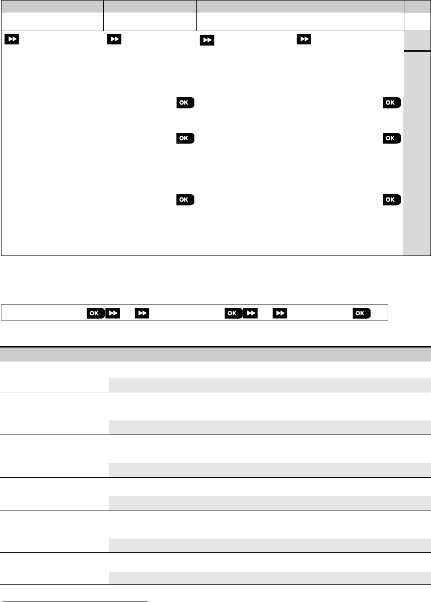
4. PROGRAMMING
32 D-305735 PowerMaster 360 Installer's Guide
Step 1
Step 2
Step 3 Step 4
Select "COMMUNICATION"
Select Communication
Sub-menu option
Select the "Communication" Parameter you wish to configure
See
→1st SMS/MMS
→2nd SMS/MMS
→3rd SMS/MMS
→4th SMS/MMS
5:MOTION CAMERA
VIEW ON DEMAND
4.6.5
VIEW TIME WINDOW
VIEW OTHER ALARM
6:UP/DOWNLOAD
UP/DWNLOAD PARAM
GPRS UP/DOWNLOAD
4.6.6
→Remote access
→Panel SIM Tel. #
→Mast. UL/DL code
→1st caller ID#
→Inst. UL/DL code
→2nd caller ID#
→UL/DL Modes
7:BROADBAND 1
DHCP Client
RESET MODULE
4.6.7
Manual IP
PLNK curr.params
→Curr.IP address
→Curr.subnet mask
→Current Gateway
4.6.2 Configuring GSM-GPRS (IP) - SMS Cellular Connection
The GSM/GPRS module is capable of communicating with the Monitoring station receiver by GPRS or SMS Channels.
The GPRS channel is always enabled. If fails, the GPRS module will try to communicate via SMS.
04:COMMUNICATION
⋅⋅⋅
2:GSM/GPRS/SMS
⋅⋅⋅
MENU you wish
Enter "2:GSM/GPRS/SMS", select the menu you wish to configure (see guidance above and in section 4.6.1), then
refer to the table below which provides you with detailed explanations and configuration instructions for each option.
Option Configuration Instructions
SMS REPORT Define whether the system will report events to the Monitoring Stations' SMS receivers
via the SMS Channel. For further information, see section 4.6.3 options 26 & 27.
Options: disable (default); enable.
GPRS APN
Enter the name of the APN Access Point used for the internet settings for the GPRS
(up to 40 digits string).
Note:
To enter the APN Access Point, use the
"String Editor"
in section 4.8.1.
GPRS USERNAME Enter the Username of the APN used for GPRS communications (up to 30 digits string).
Note: To enter the Username, use the "String Editor" in section 4.8.1.
SIM PIN CODE
Enter the PIN code of the SIM card installed in the GSM module (up to 8 numerical
digits).
Note: To enter the numerical PIN code, use the numerical keyboard.
GPRS PASSWORD Enter the Password of the APN used for GPRS communications (up to 16 digits string).
Note: To enter the Password, use the "String Editor" in section 4.8.1.
1 The name of the product is PowerLink3 IP Communicator
4. PROGRAMMING
D-305735 PowerMaster 360 Installer's Guide 33
NETWORK ROAMING
Previously known as "FORCE
HOME NTWK"
You can force the SIM card to use only its "Home Network" and disable it from roaming
to other networks in case the Home Network cannot be found.
Options: roam disable; roam enable (default).
GPRS ALWAYS ON
Previously known as
"SESSION TIMEOUT"
Define whether the control panel will stay continuously connected "enabled", via GPRS
communication, or disconnect "disabled" (default), after each report session.
GSM KEEP ALIVE Some GSM Service providers tend to disconnect the GSM connection if the user has not
initiated any outgoing telephone calls during the last 28 days. To prevent from
disconnecting the GSM connection, you can configure the system to generate a "keep
alive" GSM call every 28 days sending a test message either to the first SMS number
(if exists) or alternatively first private telephone number.
Options: Disable (default) or Every 28 days.
TRANS. PROTOCOL Select the IP protocol used to transfer data over the internet/GPRS.
Options: TCP (default); or UDP.
4.6.3 Configuring Events Reporting to Monitoring Stations
The PowerMaster 360 control panel is designed to report alarm, alerts, troubles and other events and messages to two
Monitoring Stations C.S.1 and C.S.2 via Cellular i.e. GPRS (IP) & SMS or Broadband IP communications channels. In
this section you configure and define all parameters and features required for the reporting of the event messages to
Monitoring Stations such as:
• The events reported to each of the two Monitoring Stations C.S.1 and C.S.2 and corresponding backups.
• The communication means (channel) used for the reporting and the backup means (channel) in case of failure.
• The customer's (subscriber) account number(s) to be reported to each Monitoring Station.
• The IP addresses, SMS numbers and reporting formats of the corresponding alarm receivers at the two Monitoring
Stations C.S.1 and C.S.2 and the number of reporting retry attempts in case of failure to report.
• The communication Auto Tests and communication Fail reports.
• The reporting of certain system function events such as "Confirmed Alarm", "Recent Close", Zone Restore" and
"System Not-Used".
04:COMMUNICATION
⋅⋅⋅
3:C.S.REPORTING
⋅⋅⋅
MENU you wish
Enter "3:C.S.REPORTING", select the menu you wish to configure (see guidance above and in section 4.6.1), then
refer to the table below which provides you with detailed explanations and configuration instructions for each option.
Option Configuration Instructions
01:REPORT EVENTS
Define which events (i.e. Alarms (alrm); Open/close (o/c); Alerts (alrt); All events (all);
Maintenance and Troubles) will be reported to the Monitoring Stations.
The minus (-) symbol means "less/except" e.g. all(-alrt) means all events except alerts.
The asterisk (
) is a separator between events reported to Monitoring Station 1 (C.S.1) and
events reported to Monitoring Station 2 (C.S.2). For detailed and more complete explanation
see the "Event Reporting Chart" at the end of this section.
Options:
all-o/c backup (default)
all-o/co/c
disable report
all all
all(-alrt)alrt
all backup
all-o/call-o/c
alrmall(-alrm)
Note: Alarm events (alrm) have highest priority and Alert events (alrt) have lowest priority.
02:1st RPRT CHAN
If the system is equipped also with Cellular communicators, you must define which of the
communicating channels (i.e. Cellular or Broadband) the system will use as the main channel
(i.e. 1st priority) for reporting event messages to Monitoring Stations.
Enter the "1st RPRT CHAN"; option and define which of the communication channels the
system will use as the main reporting channel.
Options: broadband first (default); disable; and cellular first.
Important:
If the selected main reporting channel fails, the system will use the other
communication channel to report event messages to Monitoring Stations. If none
is selected, the reporting to Monitoring Stations will be disabled.
4. PROGRAMMING
34 D-305735 PowerMaster 360 Installer's Guide
Option
Configuration Instructions
05:DUAL REPORT Define whether or not to report events using broadband and cellular communication channels.
Options: disable (default); broadbnd & cell.
11:RCVR1 ACCOUNT
12:RCVR2 ACCOUNT
Enter the respective 1st Account (subscriber) number (11:RCVR 1 ACCOUNT) that will identify
your specific alarm system to the 1st Monitoring Station (designated as RCVR1 or RCV1) and a
2nd Account (subscriber) number (12:RCVR 2 ACCOUNT) that will identify the system to the 2nd
Monitoring Station (designated as RCVR2 or RCV2). Each of the Account numbers consists of
6 hexadecimal digits.
Master Installer only
To enter Hexadecimal digits, use the following table:
Entering Hexadecimal Digits
Digit
0…..9
A
B
C
D
E
F
Keying
0…..9
[#]
[0]
[#]
[1]
[#]
[2]
[#]
[3]
[#]
[4]
[#]
[5]
21:IP RCVR 1
22:IP RCVR 2
Master Installer only
The PowerMaster 360 can be programmed to report the event messages defined in Report
Events option (option 01) to two IP Receivers, Visonic PowerManage model. IP reporting can be
performed via GPRS (IP) channel using SIA IP format or via Broadband IP channel using SIA IP.
Enter the two IP addresses (000.000.000.000) of the IP Receiver 1 located at the 1st Monitoring
Station (21:IP RCVR 1) and IP Receiver 2 located at the 2nd Monitoring Station (22:IP RCVR 2).
26:SMS RCVR 1
27:SMS RCVR 2
Master Installer only
If equipped with GSM module, the PowerMaster 360 can be programmed to report the event
messages defined in Report Events option (option 01) to two SMS Receivers via the GSM
SMS channel using a special SMS text format. For further details concerning the SMS text
format please contact Visonic.
Enter the two telephone numbers (including area code – maximum 16 digits).of the SMS
Receiver 1 located at the 1st Monitoring Station (26:SMS RCVR 1) and SMS Receiver 2
located at the 2
nd
Monitoring Station (27:SMS RCVR 2).
Note:
To enter the international prefix (
) at the 1st digit – key-in [#]
[1].
47:GSM RETRIES Define the number of times the system will retry to report to the Monitoring Station in case of
failure to report via the cellular connection - GPRS (IP) and SMS.
Options: 2 attempts; 4 attempts (default); 8 attempts; 12 attempts and 16 attempts.
48:BB IP RETRIES Define the number of times the system will retry to report to the Monitoring Station in case of
failure to report via the Broadband Module connection.
Options: 2 attempts; 4 attempts (default); 8 attempts; 12 attempts and 16 attempts.
51: AUTO-TST LOOP To verify a proper communication channel, the PowerMaster 360 can be configured to send a
test event to the Monitoring Station periodically. You can set the interval between the consecutive
test events or disable the automatic sending of this event entirely. If the interval is set for every
one day or more then the exact hour of reporting can be selected with option 52.
Options:
test OFF
(default);
every 1
/
2
/
5
/
7
/
14
/
30 day(s)
; and
every 5 hours
.
52:AUTO TST TIME
Enter the exact time (auto test time) during the day at which the Auto Test message (if
enabled in option 51) will be sent to the Monitoring Station.
Note: If the AM/PM format is used, you can set the "AM" digit with the button and the
"PM" digit with the button.
53:COM.FAIL RPRT
→
GSM/GPRS FAIL
(Return)
Determine whether a failure in the system communication channel i.e. GSM/GPRS will be
reported or not and the time delay between detection of the failure and reporting of the failure
event to the Monitoring Station. A trouble event (i.e. "GSM line fail") will be respectively stored
in the event log.
Previously known as
"LINE FAIL REPORT" Options: after 2/5/15/30 min and do not report (default).

4. PROGRAMMING
D-305735 PowerMaster 360 Installer's Guide 35
Option
Configuration Instructions
61:RPRT CNF ALRM Define whether the system will report whenever 2 or more events (confirmed alarm) occur
during a specific period or enable the report and bypass the detector.
Options: rprt disabled (default), rprt ena+bypass and rprt enabled
Note: In some PowerMaster 360 variants, this menu is displayed in the Operation Mode only.
62:RECENT CLOSE
False alarms may occur if users do not exit the premises within the exit delay period, resulting
in a false alarm a short time later. In such cases, inform the Monitoring Station that the alarm
occurred shortly after the system was armed (this event is known as "Recent Close"). The
report enabled option sends a “recent closing” report to the Monitoring Station if an alarm
occurs within 2 minutes from the end of the exit delay.
Options: report disabled (default) and report enabled
63:ZONE RESTORE Some Monitoring Stations require that following an alarm event from a specific zone, the
system will also report when the alarming zone has restored to normal.
Options: report enabled (default) and report disabled
64:SYST.INACTIVE The PowerMaster 360 can report a "System Inactive" event message (CID event 654) to the
Monitoring Station if the system is not used (i.e. armed) during a predefined time period.
Options: report disabled (default); after 7/14/30/90 days.
66:24H ZONE RPRT
Applicable in UK only
Define whether 24 hour (silent and audible) zones will function as normal 24 hour zones or as
panic zones.
Options: audibl as panic; silent as panic; both as panic; and both burglary (default).
Event Reporting Chart
To simplify the configuration of reporting system events to Monitoring Stations, the event messages are divided into 4
Event Groups as described in the following table below: Due to lack of space in the display, the following abbreviations
are used alrm, alrt, o/c” and all (i.e. all events).
Event Group Abbr. Events Messages Reported
Alarms
alrm
Fire, CO, Burglary, Panic, Tamper
Open/close
o/c
Arming AWAY, Arming HOME, Disarming
Alerts
alrt
No-activity, Emergency, Latchkey
Trouble - All other Trouble events not indicated above, e.g. Missing, Jamming, Communication Fail,
Low Battery, AC failure etc.
Note: "Alarms" group has the highest priority and "Alerts" group has the lowest priority.
The PowerMaster 360 allows you also to select which event groups will be reported to each of the two Monitoring
Stations. The table below describes the available reporting options. The minus (-) symbol means "but/less/except" e.g.
all(-alrt) means all events except alerts. The asterisk (
) is a separator between event messages reported to
Monitoring Station 1 (C.S.1) and event messages reported to Monitoring Station 2 (C.S.2).
Available Reporting Options Events Reported to C.S. 1 Events reported to C.S. 2
"all backup"
All
All, only if C.S.1 does not respond
"all-o/c backup"
All but open/close
All but open/close, only if C.S. 1 does not respond
"all all"
All
All
"all-o/c
all-o/c "
All but open/close
All but open/close
"all–o/c o/c "
All but open/close
Open/close
"all(–alrt)
alrt"
All but alerts
Alerts
"alrm all(–alrm)"
Alarms
All but alarms
"disable report"
None
None
Note: “all” means that all 5 Groups are reported including Trouble messages - sensor / system low battery, sensor
inactivity, power failure, jamming, communication failure etc.
4. PROGRAMMING
36 D-305735 PowerMaster 360 Installer's Guide
4.6.4 Configuring Events Reporting to Private Users
The PowerMaster 360 system can be programmed to send various SMS event notifications such as alarm, arming or
trouble events, if a GSM option is installed. The system can send the messages also to 4 emails, MMS and SMS
telephone numbers via the server. These reports can be programmed either instead of or in addition to the reports
transmitted to the monitoring company. In this section you configure:
• The specific events you wish the system to report.
• The 1st, 2nd, 3rd, and 4th SMS numbers of the private subscribers.
• Event notification messages to be sent to 1st, 2nd, 3rd, and 4th private emails and private MMS and SMS telephone
numbers via the server.
To select and configure an option follow the instructions below. Additional guidance is provided in section 4.6.1.
04:COMMUNICATION
⋅⋅⋅
4:PRIVATE REPORT
⋅⋅⋅
MENU you wish
The "4:PRIVATE REPORT" menus and sub-menus configuration is shown in the table in section 4.6.1. For a detailed
description of the menus options, refer to the User's Guide Chapter 4, section B.12.
4.6.5 Configuring Motion Cameras for Visual Alarm Verification
The PowerMaster 360 can communicate to Monitoring Stations (equipped with Visonic PowerManage server) with
image clips captured by Motion Cameras (models Next CAM PG2, Next-K9 CAM PG2 and TOWER CAM PG2). The
Monitoring Station can use the video clips for verification of Burglary alarms detected by the Motion Cameras. The
system can be configured to capture image clips also upon occurrence of Non-Burglary alarms (i.e. Fire, Duress,
Emergency and Panic). The server can then forward the images to the management computer of the Monitoring
Station or to 4 private emails and/or 4 mobile phones by MMS images.
In addition, the Monitoring Station can log into the PowerManage server and request the system to provide image clips
"On Demand" and to forward them as defined in the PowerManage application. To protect customers' privacy, the
PowerMaster 360 can be customized to enable the "On Demand View" only during specific system modes (i.e. Disarm,
Home and Away) and also to a specific time window following an alarm event.
04:COMMUNICATION
⋅⋅⋅
5:MOTION CAMERAS
⋅⋅⋅
MENU you wish
Enter "5:MOTION CAMERAS", select the menu you wish to configure (see guidance above and in section 4.6.1), then
refer to the table below which provides you with detailed configuration instructions.
Option
Configuration Instructions
VIEW ON DEMAND By enabling the "On Demand View", you can determine during which arming modes (system
states) the "On Demand View" will be permitted. In the next option "VIEW TIME WINDOW" you
can determine when, during the permitted arming modes, the "On Demand View" will be enabled.
Options: disabled (default); in all modes; in AWAY only; in HOME only; in HOME & AWAY;
DISARM & AWAY; DISARM & HOME; and in DISARM only.
VIEW TIME WINDOW
VIEW TIME WINDOW
menu appears only if
VIEW ON DEMAND
was enabled
If the "On Demand View" is enabled in the previous option, you can further determine whether
the "On Demand View" will be possible at any time during the selected arming modes (i.e.
"Always") or restricted only to a specific limited time window that follows an alarm event.
Options: Always (default); Alarm + 5 min.; Alarm + 15 min.; Alarm + 1 hour
VIEW OTHER ALARM Define whether the system will capture and forward image clips also upon occurrence of Non-
Burglary alarms (i.e. Fire, Duress, Emergency and panic).
Options: Enable (default); Disable.
KIDS COME HOME Define that upon PIR-camera detection, the system will send up to 4 images to a 3rd party
server if the system is disarmed via keypad or proximity tag by latchkey users 5 to 8 and only
when the system was in Entry Delay or the Abort Time was enabled.
Options: Enable; Disable (default).
Note: At least one PIR camera must be defined as one of the following zone types:
Perim-Follow / Inter-Follow / Exit/Entry 1 / Exit/Entry 2.
UPLOAD FILM
Define whether to enable / disable the sending of images to the PowerManage server.
Options:
Enable
(default)
; Disable
.
4. PROGRAMMING
D-305735 PowerMaster 360 Installer's Guide 37
4.6.6 Configuring Upload / Download Remote Programming Access Permission
Using a PC, the PowerMaster 360 can be configured (by upload/download) either locally or from remote via GPRS
cellular communication.
Local programming can be performed by directly connecting the computer to the panel's USB port using the Remote
Programmer PC Software.
Remote programming via GPRS is performed using a Visonic PowerManage server and related Remote Programmer
PC software. The PowerManage server calls from a cellular modem to the Panel's SIM card number. The panel checks
the caller ID and if identical with any of the two callers ID 1 or 2 programmed in the "GPRS UP/DOWNLOAD" menu
(see table below), the panel initiates a GPRS connection with the respective IP Receiver 1 or 2 (as configured in
section 4.6.3 options 21 & 22). When connection is established, the monitoring company can perform the
upload/download procedure via the established secured GPRS connection. For further information refer to the
PowerManage User's Guide.
In this section you can configure the access permissions (i.e. security codes and identification) and determine the
functionality of the upload/download procedures via GPRS channel.
04:COMMUNICATION
⋅⋅⋅
6:UP/DOWNLOAD
⋅⋅⋅
MENU you wish
Enter "6:UP/DOWNLOAD", select the menu to configure (see guidance above and in section 4.6.1), then refer to the
table below for configuration instructions.
Option Configuration Instructions
UP/DWNLOAD PARAM Configure the Upload/Download functionality. The functionality is determined through a sub-
menu of the " UP/DOWNLOAD" option as shown below.
To program:
Press to enter the " UP/DOWNLOAD" sub menu and then select and configure each of
the sub-menu options as shown below. When done, press to return.
→
Remote access Enable or disable the remote access to the system. If disabled, the system cannot be
accessed remotely thereby inhibiting the Upload/Download and the Remote Control via
GSM analog communication channel (see Chapter 5 in the User's Guide).
Options: enabled (default); disabled.
→
Mast. UL/DL code Enter the 4-digit password (Master Installer download code) code that will allow the Master
Installer to access the system remotely and upload/download data to the PowerMaster 360
panel.
Note: "0000" is not a valid code and must not be used.
→
Inst. UL/DL code Enter the 4-digit password (Installer download code) code that will allow the Installer to
access the system from remote and upload or download data into the PowerMaster 360
panel.
Notes:
1. "0000" is not a valid code and must not be used.
2. The installer can configure via UL/DL only the options he is authorized to configure from
the control panel.
→
UL/DL modes
Define whether the downloading/uploading can be performed in Disarm mode (state) only or
in all modes (i.e. Away, Home & Disarm).
Options: in all modes (default) or in DISARM only.
(Return)
GPRS UP/DOWNLOAD Configure the Upload/Download functionality via GPRS. The functionality is determined
through a sub-menu of the "GPRS UP/DOWNLOAD" option as shown below.
To program:
Press to enter the "GPRS UP/DOWNLOAD" sub menu and then select and configure
each of the sub-menu options as shown below. When done, press to return.
→
Panel SIM Tel.#
(Previously known as
"My SIM Tel.#")
Enter the PowerMaster 360 SIM card telephone number. The PowerManage server at the
Monitoring Station sends an SMS or voice message to this number for the panel to call back
the PowerManage server via GPRS for initiating the uploading / downloading process.
Enter the SIM card telephone number of the panel's GSM module.
4. PROGRAMMING
38 D-305735 PowerMaster 360 Installer's Guide
Option
Configuration Instructions
→
1st caller ID#
→
2nd caller ID#
Enter the "Caller ID" (i.e. telephone number) from which Monitoring Station #1 (C.S.1) /
Monitoring Station #2 (C.S.2) calls the control panel for initiating the Up/Download
process. If the sender's Caller ID matches with the "1st caller ID#" / "2nd caller ID#", the
PowerMaster 360 will call back the PowerManage server using "IP RCVR 1" / "IP RCVR 2"
address as configured in Section 4.6.3, options 21 and 22.
Note: Caller ID#1/ID#2 must contain at least 6 digits otherwise the process will not work.
(Return)
4.6.7 Broadband1
Note: If the Broadband Module is not registered to the PowerMaster 360, the menu "7:BROADBAND" will not be
displayed.
In this section you can configure how to obtain an IP address, enter LAN parameters and reset broadband module
settings. In addition, the “PLNK curr.params” menu enables reading the current IP addresses of the PowerLink for
support purposes only.
04:COMMUNICATION
⋅⋅⋅
7:BROADBAND
⋅⋅⋅
MENU you wish
Enter "7:BROADBAND", select the menu to configure (see guidance above and in section 4.6.1), then refer to the
table below for configuration instructions.
Option Configuration Instructions
DHCP Client Define whether to obtain an IP address automatically using a DHCP server or to enter an
IP address manually.
Options: disable; enable (default).
Manual IP Manually enter LAN parameters.
Note: This menu will appear only if DHCP Client is disabled.
PLNK curr.params Displays the current IP addresses of the PowerLink.
→
Curr.IP address Displays the current PowerLink IP address.
→
Curr.subnet mask
Displays the current PowerLink subnet mask.
→
Current Gateway Displays the current PowerLink default gateway.
RESET MODULE Determine whether to reset the broadband module (reboot).
1 The name of the product is PowerLink3 IP Communicator
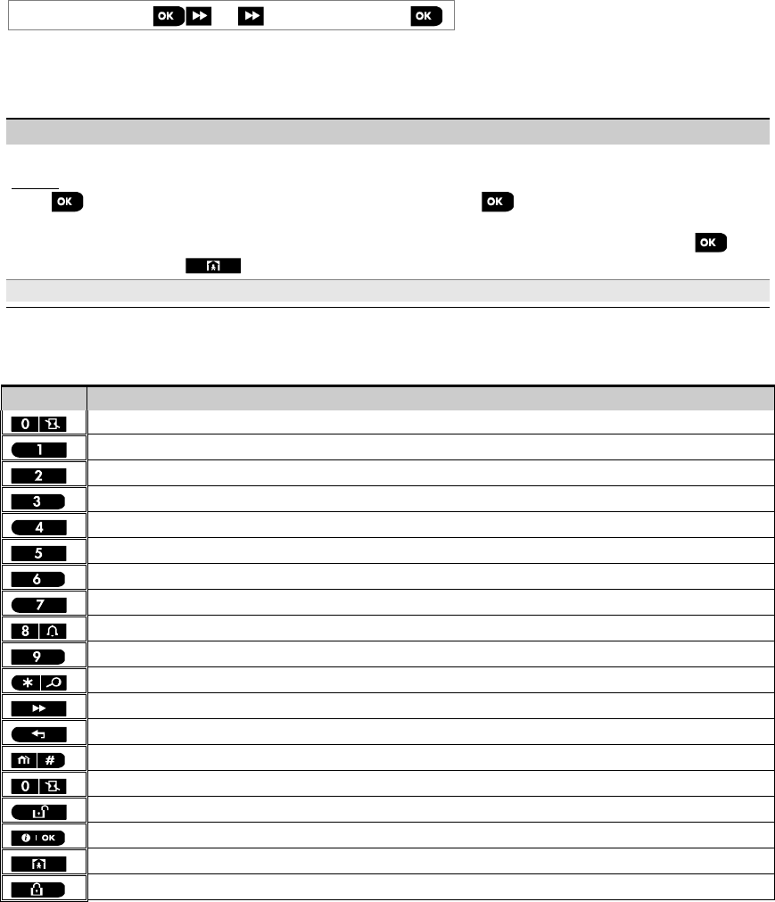
4. PROGRAMMING
D-305735 PowerMaster 360 Installer's Guide 39
4.7 Custom Names
4.7.1 Custom Zone Names
During the device enrollment process you also define the Location name where the device is installed. The location
name is selected from a Location List of Custom names - see Section 4.4.2, Part B, for Location List and instructions.
Define the custom location names according to your specific needs and use them during device enrollment.
To define the Custom Location names, follow the instructions below. Additional guidance is provided in section 4.2.
06:CUSTOM NAMES
⋅⋅⋅
CUST.ZONES NAME
Enter "CUST.ZONES NAME" (see guidance above), then refer to the table below which provides you with detailed
explanations and programming instructions to edit the desired custom location.
Note: The following custom names can be edited: Master Bdrm, Office, Upstairs, Utility Room, Yard, Custom 1,
Custom 2, Custom 3, Custom 4 and Custom 5.
Configuration Instructions
Enter the Custom Location names you wish to edit.
To edit:
Press to enter the "CUST. ZONES NAME" sub menu and then press again to select the Location # you wish
to edit, for example "TEXT LOC. #01" – the display alternates with the current Custom name, for example, "Master
Bdrm". To change the name, at the blinking cursor, enter the Location name you wish and at the end, press to
confirm. When done, press to return.
Note: To enter the Location name use the "String Editor" below.
IMPORTANT! The editing of a custom zone name automatically deletes the original text.
PowerMaster 360 String Editor
Key String Editor Functionality
' ', '0'
'.', ',', '1'
'a', 'A', 'b', 'B', 'c', 'C', '2'
'd', 'D', 'e', 'E', 'f', 'F', '3'
'g', 'G', 'h', 'H', 'i', 'I', '4'
'j', 'J', 'k', 'K', 'l', 'L', '5'
'm', 'M', 'n', 'N', 'o', 'O', '6'
'p', 'P', 'q', 'Q', 'r', 'R', 's', 'S', '7'
't', 'T', 'u', 'U', 'v', 'V', '8'
'w', 'W', 'x', 'X', 'y', 'Y', 'z', 'Z', '9'
!, #, %, &, ', ∗, +, -, /, =, ^, @, _, “, :
Moves the digits cursor from left to right.
Moves the digits cursor from
right to left
.
Changes between lowercase letters (a,b,c…z), uppercase letters (A,B,C…Z) and numbers (1,2,3).
Clears a single digit of the string by cursor.
Clears a single digit of the string to the left of cursor.
Confirms and saves
the edited string and reverts to previous menu.
Exiting the edit screen and moves one level up to previous or top menu without saving the edit string.
Exiting
the edit screen and moves to the "<OK> TO EXIT" exit screen without saving the edit string.
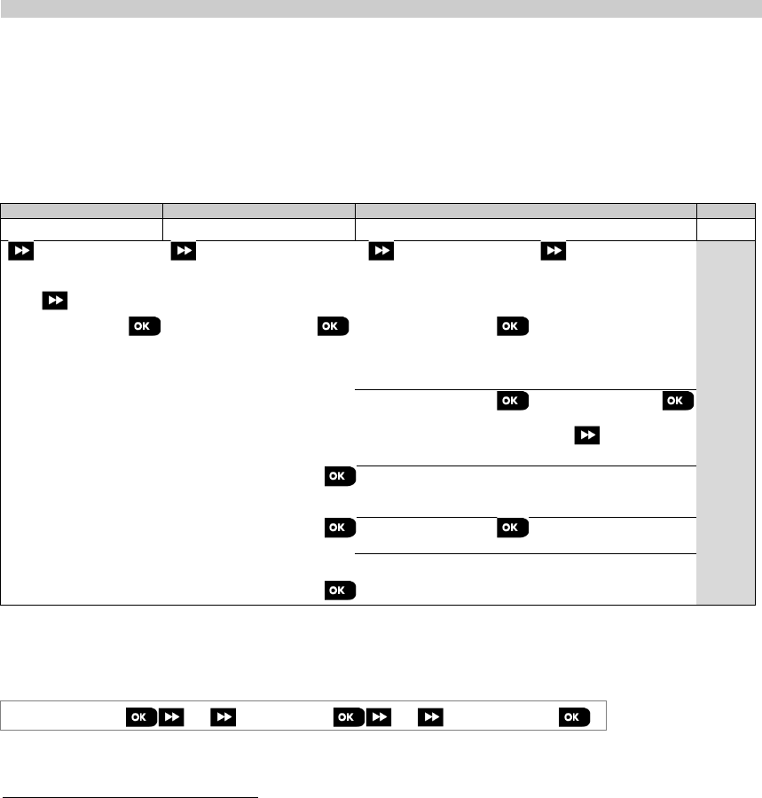
4. PROGRAMMING
40 D-305735 PowerMaster 360 Installer's Guide
4.8 Diagnostics
4.8.1 General Guidance – "Diagnostics" Flow-Chart & Menu Options
The DIAGNOSTICS menu enables you to test your system and to verify proper operation of your PowerMaster 360
panel, wireless devices attached to it and the communication (GSM/GPRS/SIM) modules.
IMPORTANT! Reliable reception must be assured during the initial testing and also throughout subsequent system
maintenance. A device should not be installed in location where signal strength is "poor". If you get "poor" signal
strength from a certain device, simply re-locate it and re-test until a "good" or "strong" signal strength is received. This
principle should be followed throughout the diagnostic test procedure.
The diagnostic test process is shown below.
The "07.DIAGNOSTICS" menu contains several sub-menu options, each covering a group of configurable features and
parameters related to the communication and reporting as follows (see the list in Step 3 of the chart below):
Option
Description of Option Features and Parameters
Section
WL DEVICES Describes how to test the devices attached to the PowerMaster 360 panel, review
devices' status and RF signal status. You can test all devices, test single device,
review devices status and review RF problems, in case of any.
4.8.2
GSM/GPRS Describes how to test the GSM/GPRS communication module.
4.8.3
SIM NUMBER TEST Tests the SIM number to ensure correct entry of the SIM number in the control
panel.
4.8.4
BROADBAND
MODULE 1 Enables to test the communication of the Broadband Module with the
PowerManage server.
4.8.5
To enter the "07.DIAGNOSTICS" menu and to select and configure an option, proceed as follows:
Step 1
Step 2
Step 3
Step 4
Select "07.DIAGNOSTICS"
Select sub-menu option
Select the diagnostics you want to perform
See
INSTALLER MODE
07.DIAGNOSTICS
WL DEVICES
TEST ALL DEVICES
4.8.2
SHOW ALL DEVICES
SHOW RF PROBLEMS
TEST ONE DEVICE
Contact sensors
Motion sensors
Repeaters
GSM/GPRS
4.8.3
SIM NUMBER TEST
1
Tst by IP RCVR 1
Tst by IP RCVR 2
SIM# verified
4.8.4
BROADBAND MODULE2
PLEASE WAIT…
Unit is OK
4.8.5
4.8.2 Testing Wireless Devices
The PowerMaster 360 enables to test the wireless devices attached to the panel. You can test all devices, one device
at a time, display devices' status and review RF problems, in case of any.
07:DIAGNOSTICS
⋅⋅⋅
WL DEVICES
⋅⋅⋅
MENU you wish
Enter the "WL DEVICES" menu, select the type of test you wish to perform (see guidance above and in section 4.8.1),
then refer to the table below which provides you with detailed explanations for each option.
1 The name of the product is PowerLink3 IP Communicator
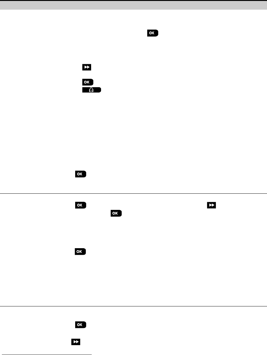
4. PROGRAMMING
D-305735 PowerMaster 360 Installer's Guide 41
Option
Instructions
TEST ALL DEVICES You can test all wall-mounted devices automatically, one after the other, after which the
installer tests the other devices in the following order: vanishing magnetic contact
devices, keyfobs and then panic buttons.
While in "TEST ALL DEVICES", press to initiate the test. The following screen will
appear: "TESTING Xxx NNN", where “Xxx” indicates the type of device and “NNN” indicates
the number of enrolled devices in the panel that have not been tested yet. This number
automatically drops one count for every tested device.
Pressing any key during the testing process will open the following options:
1. Press to jump to the next device group. For example, from wall-mounted devices to
keyfobs.
2. Press to continue the testing process
3. Press to exit the test process.
When all wall-mounted devices have completed the test procedure, you can test vanishing
magnetic contact devices.
While in the vanishing test process, indicated by the corresponding display, for example,
"TEST VANISH NNN", momentarily open the door or window.
When all vanishing magnetic contact devices have been tested, you can test keyfobs.
While in the keyfobs test process, indicated by the corresponding display, for example,
"TEST KEYFOBS NN", press any key of the selected device to initiate the test.
When all keyfobs have been tested, you can test panic buttons.
While in the panic button test process, indicated by the corresponding display, for example,
"TEST PANIC BT. NN", press a button on the pendant.
At the end of the test process, the panel will present the following: "SHOW ALL DEVICES".
Press to view devices' status.
Note: Refer to "SHOW ALL DEVICES" section below for further information on device
status.
TEST ONE DEVICE
→
CONTACT SENSORS
→
MOTION SENSORS
→
GLASSBREAK SENS.
→
SHOCK SENSORS
→
SMOKE SENSORS
→
CO SENSORS
→
GAS SENSORS
→
FLOOD SENSORS
→
TEMPERATURE SENS.
→
KEYFOBS
→
PANIC BUTTONS
→
KEYPADS
→
SIRENS
→
REPEATERS
You can select a specific device group you wish to test, for example, Motion Sensors.
Press to enter the "TEST ONE DEVICE" sub menu and use to scroll through the
device families. Press to enter the <device family> sub menu, for example:
"MOTION SENSORS".
Note: If there is no enrolled device, "
NO EXISTING DEV.
" will be displayed.
The following screens will then appear: "Xxx:<device name>"
"<location>"
Where Xxx indicates the device number. You can now select a specific device.
Press to test the selected device. The following screen will appear: "TESTING Xxx 001".
While in the keyfobs, panic button or vanishing magnetic contact test process, indicated
by the corresponding display, for example, "Xxx ACTIVATE NOW", press any key of the
selected keyfob or panic button, or momentarily open the door or window to initiate the
test.
At the end of the test process, the panel will present the devices' status:
"Xxx: 24hr: <status>"1
"Xxx: NOW: <status>"1.
Note: Refer to "SHOW ALL DEVICES" section for further information on device status.
SHOW ALL DEVICES You can view the devices status.
Note: This option is available only after testing process was done.
Press to view the devices' status.
The following screens will appear: "Xxx: 24hr: <status>"1
"Xxx: NOW: <status>"1
Use to scroll between the device's families.
1 The signal strength indications are as follows: "STRONG"; GOOD"; "POOR"; "1-WAY" (the device operates in 1-way
mode or, the "NOW" communication test failed); "NOT TST" (results are shown without any performed test); "NOT
NET" [device is not networked (not fully enrolled)]; "NONE" (keyfob 24Hr result); or "EARLY" (result of the last 24Hrs
without statistics).
4. PROGRAMMING
42 D-305735 PowerMaster 360 Installer's Guide
Option
Instructions
To view additional information of the selected device, press .
The following screens will
appear: " Xxx <device name>"1
" <location>"1.
If the control panel receives information via a repeater, it will be displayed as follows:
"
Xxx <device name>
"1
"
<location>
"1
“
RPx:Via Repeater
”
SHOW RF PROBLEMS You can view only the devices which have RF problems.
Note: This option is available only after testing process was done.
Press to view the devices' status.
The following screens will appear: "Xxx: 24hr: <status>"1
"Xxx: NOW: <status>"1
Use to scroll between the device's families.
To view additional information of the selected device, press .
The following screens will
appear: " Xxx <device name>"1
" <location>"1.
If the control panel receives information via a repeater, it will be displayed as follows:
"
Xxx <device name>
"1
"
<location>
"1
“
RPx:Via Repeater
”
<OK> TO END Select to terminate the diagnostics test.
4.8.3 Testing the GSM module
The PowerMaster 360 enables to test the panel’s integrated GSM module.
07:DIAGNOSTICS
⋅⋅⋅
GSM/GPRS Please wait…
Enter the "GSM/GPRS" menu, and press to initiate the GSM diagnostic test. Upon test completion, the
PowerMaster 360 will present the test result.
The following table presents the test result messages.
Message
Description
Unit is OK
GSM / GPRS is functioning correctly
GSM comm. loss
GSM/GPRS module does not communicate with the Panel
Pin code fail
Missing or wrong PIN code. (Only if SIM card PIN code is enabled.)
GSM net. fail
Unit failed with registration to local GSM network.
SIM card fail
SIM not installed or SIM card failure.
GSM not detected
GSM auto enroll failed to detect GSM/GPRS module.
No GPRS service
The SIM card does not have the GPRS service enabled.
GPRS conn. fail
Local GPRS network is not available or, wrong setting to GPRS APN, user and/or password.
Srvr unavailable
PowerManage receiver cannot be reached – Check the Server IP
IP not defined
Server IP #1 and #2 are not configured.
APN not defined
APN is not configured.
SIM card locked
After entering a wrong PIN code 3 consecutive times the SIM is locked. To unlock it enter a PUK
number. The PUK number cannot be entered by the control panel.
Denied by server PowerManage denies the connection request. Check that the panel is registered to
PowerManage.
4.8.4 Testing the SIM Number
The PowerMaster 360 enables to test the SIM number to ensure the SIM number was entered correctly in the control
panel (see section 4.6.2) and to coordinate with the operator.
07:DIAGNOSTICS
⋅⋅⋅
SIM NUMBER TEST
⋅⋅⋅
Enter the "SIM NUMBER TEST" menu, select the IP server (out of two) used for the verification of the SIM and press
. The panel sends a test SMS to the server.
If the server receives the SMS, the control panel will display “SIM# verified” and the test ends successfully. If the SMS
was not received, for example, if there is no connection between the control panel and server, the control panel will
display “SIM not verified”.

4. PROGRAMMING
D-305735 PowerMaster 360 Installer's Guide 43
4.8.5 Testing the Broadband/PowerLink Module 1
The Broadband diagnostic procedure enables to test the communication of the Broadband Module (see section 4.6.7)
with the PowerManage server and reports the diagnostic result. In case of communication failure, detailed information
of the failure is reported.
07:DIAGNOSTICS
⋅⋅⋅
BROADBAND MODULE
⋅⋅⋅
PLEASE WAIT… Unit is OK
Notes:
1. When the button is pressed, the test result may take up to 4 min. before it is displayed.
2. If the Broadband Module is not registered to the PowerMaster 360, the menu "BROADBAND MODULE" will not be
displayed.
The following table presents the list of messages that may be reported:
Message
Description
Unit is ok
Broadband Module is functioning correctly.
Test aborted The diagnostic test is aborted, as follows:
• AC failure – Broadband Module is set to OFF mode.
• Broadband Module has not completed the power-up procedure. In this case, the installer should
wait a maximum of 30 seconds before re-testing.
Comm. loss
The RS-232 serial interface between the Broadband Module and the PowerMaster 360 failed.
Rcvr Ip missing
Receivers IP 1 and 2 settings are missing in the PowerMaster 360.
Cable unplugged
The Ethernet cable is not connected to the Broadband Module.
Check lan config This message appears in any of the following cases:
• Incorrect Broadband Module IP has been entered.
• Incorrect subnet mask has been entered.
• Incorrect default gateway has been entered.
• DHCP server failure.
Rcvr#1 UnReach.
Rcvr#2 UnReach.
Receiver 1 or 2 is inaccessible, as follows:
• Wrong receiver IP has been entered.
• Receiver failure.
•
WAN Network failure.
Rcvr#1 UnReg.
Rcvr#2 UnReg.
The PowerMaster 360 unit is not registered to IP receiver 1 or 2.
Timeout err.
Broadband Module does not respond to test result within 70 sec.
Invalid result
Broadband Module responds with a result code that is not recognized by the PowerMaster 360.
4.9 User Settings
This USER SETTINGS menu provides you with a gateway to the user settings through the regular user menus.
Refer to the PowerMaster 360 User's Guide for detailed procedures.
1 The name of the product is PowerLink3 IP Communicator
4. PROGRAMMING
44 D-305735 PowerMaster 360 Installer's Guide
4.10 Factory Default
The FACTORY DEFLT menu enables you to reset the PowerMaster 360 parameters to the factory default parameters.
To obtain the relevant parameters defaults, contact the PowerMaster 360 dealer. Reset factory default parameters as
follows:
Step 1 Step 2 Step 3 Step 4 Step 5
Select "09:FACTORY DEFLT"
menu
Select "<OK> to restore"
Enter Installer Code
Resetting of factory default
parameters is underway
09:FACTORY DEFLT
<OK> to restore
ENTER CODE:
PLEASE WAIT…
to Step 1
Notes:
1) For PowerMaster 360 with 2 installer codes, INSTALLER code and MASTER INSTALLER code, only the master
installer code enables to perform the factory default function.
2) If the Soak Test is active, performing factory default will restart the Soak Test.
4.11 Serial Number
The SERIAL NUMBER menu enables reading the system serial number and similar data for support purposes only. To
read the system serial number and other relevant data proceed as follows:
Step 1
Step 2
Step 3
Select "10:SERIAL
NUMBER" menu
[1]
Click next repeatedly to view
relevant data.
[2]
10:SERIAL NUMBER
to Step 1
Definition
0907030000.
Control panel serial number
JS702766 L18.154
Control panel software version
PANEL ID: 100005
Control panel ID for
PowerManage connectivity
J-702770 L18.154
Control panel default version
JS702767 L01.023
Control panel boot version
JS702768 L02.003
Control panel Remote
Software Upgrade downloader
version
PL8.0.10 1111
Displays the PowerLink
software version
4.12 Partitioning
4.12.1 General Guidance – "Partitioning" Menu
This menu allows you to enable/disable partitions in the system (for further details, see APPENDIX E).
4.12.2 Enabling / Disabling Partitions
To enable or disable the partition feature, proceed as follows:
Step 1
Step 2
Step 3
Step 4
Select "12:PARTITIONING" menu
Select whether to "Enable" or "Disable"
Partitions
Partitions are
now enabled
12:PARTITIONING Disable
Enable
Enable
to Step 1
4. PROGRAMMING
D-305735 PowerMaster 360 Installer's Guide 45
4.13 Operation Mode
Note: The Operation Mode feature is applicable only in specific PowerMaster 360 variants.
4.13.1 General Guidance – "Operation Mode" Menu
This mode allows you to select an operation mode for the control panel according to specific compliance standards.
Each operation mode has its own configuration.
4.13.2 Select setting
To select the desired operation mode, proceed as follows:
Step 1 Step 2 Step 3 Step 4
Select "13:OPERATION MOD" menu
Enter "01:SELECT MODE"
Select “NORMAL”, "EN-50131",
"DD243", "BS8243", “INCERT” or
“CP01"
13:OPERATION MOD
01 SELECT MODE
NORMAL
to Step 2
Note: If "Normal / EN-50131 / INCERT" is selected, the control panel will operate according to OTHERS setup
configuration (see section 4.13.6).
4.13.3 BS8243 Setup
13:OPERATION MOD
⋅⋅⋅
02:BS8243 SETUP
Enter the "02:BS8243 SETUP " menu to configure its settings.
Option Configuration Instructions
01:DISARM OPTION
Define when it is possible to disarm the system:
entry/BS devs (default) – By keypad after the entry delay has expired and if an alarm occurred
in the system. By keyfob or KP-160 PG2 at all times.
entry/all devs - During entry delay, when the system is armed AWAY, by all devices. When
not in entry delay by keyfob or KP-160 PG2 only.
entry/DD devs - During entry delay, when the system is armed AWAY, by using the keyfob or
KP-160 PG2. Keypads cannot disarm at all.
anytime/all dev – At any time and by all devices.
02:ENTRY ALARM Define whether the system will report a confirmed alarm during an entry delay (see CONFIRM
ALARM below).
BS8243 (default) – An alarm initiated by another detector during the entry delay is regarded as
a confirmed alarm. An additional 30 seconds delay is added to the entry delay for reporting the
event (does not affect the Abort Time, see section 4.5.4).
BS8243 no cnfrm - The panel will not send any confirmed alarm once a delay zone has been
activated, until the control panel is disarmed.
DD243 - An alarm initiated by another detector during the entry delay is not regarded as a
confirmed alarm.
normal mode - The control panel will report a confirmed alarm for the second alarm that is
triggered from a different zone within the confirmation time. There are no alarm restrictions
during entry delay or for the delay zone.
03:END EXIT MODE
Define how the exit delay is terminated or restarted according to the following options:
door/fob only (default) -
When the door is closed, or by pressing the AUX button on the
keyfob1, whichever first.
restart>reentry - Exit delay restarts when the door is reopened during exit delay. The restart
occurs once only. Restarting the exit delay is helpful if the user re-
enters immediately after
going out to retrieve an item that was left behind.
door/fob/timer - When the door is closed, by pressing the AUX button on the keyfob1, or when
the exit delay has expired, whichever first.
fob/timer - By pressing the AUX button on the keyfob1
, or when the exit delay has expired,
whichever first.
1 Applies only when the keyfob is defined as "skip exit delay" (for further details, see the keyfob's User's Guide)
4. PROGRAMMING
46 D-305735 PowerMaster 360 Installer's Guide
Option
Configuration Instructions
04:FOB/KP PANIC
Define the devices that cannot trigger a panic alarm.
BS8243 (default) – KF-234 PG2 and KF-235 PG2.
all - All devices can trigger a panic alarm
05:CONFIRM ALARM Define a specific time period that if 2 successive alarms occur, the second alarm will be
considered as a confirmed alarm, (see RPT CNFM ALRM below).
Options: in 30 (default)/45/60/90 minutes
06:CONFIRM PANIC
A confirmed panic alarm is reported if one of the following occurs within the confirmation time:
a) A second panic device is activated.
b) A second panic alarm on the same device is activated.
c) A tamper event is activated (not from the zone / device that initiated the panic alarm).
Options:
in 4
/
8
/
12
/
20
(default)/
24 hours
and
disabled
07:RPT CNFM ALRM
Define whether the system will report a confirmed alarm.
enable + bypass (default) -
The system will report a confirmed alarm and will bypass all
alarmed open zones when the siren ends or when the confirmation timer expires.
disable - The system will not report a confirmed alarm.
enable
- The system will report a confirmed alarm.
08:ENTRY DELAY 1
09:ENTRY DELAY 2 Two different entry delays allow the user to enter the protected site (while the system is in the
armed state) via 2 specific doors and routes without causing an alarm.
Following entry, the user must disarm the control panel before the entry delay expires. Slow-
rate warning beeps start sounding once the door is opened, until the last 10 seconds of the
delay, during which the beeping rate increases. Locations No. 1 (entry delay 1) and 2 (entry
delay 2) allow you to program the length of these delays.
Options: 10/15/30(ENTRY DELAY 1 default)/45/60(ENTRY DELAY 2 default) seconds;
3/4 minutes
10:ABORT TIME The PowerMaster 360 can be configured to provide a delay before reporting an alarm to the
Monitoring Station (not applicable to alarms from FIRE, 24H SILENT and EMERGENCY
zones). During this delay period, the siren sounds but the alarm is not reported. If the user
disarms the system within the delay time, the alarm is aborted. You can activate the feature
and select the "Abort Time" interval.
Options: in 00 (default in USA)/15/30 (default)/45/60 seconds; in 2/3/4 minutes
11:CANCEL ALARM The PowerMaster 360 can be configured to provide a ”Cancel Alarm” time window that starts
upon reporting an alarm to the Monitoring Station. If the user disarms the system within that
"cancel alarm" time, a “cancel alarm” message is sent to the Monitoring Station indicating that
the alarm was canceled by the user.
Options: not active (default in USA); in 1/5 (default)/15/60 minute(s) and in 4 hours.
4.13.4 DD243 Setup
13:OPERATION MOD
⋅⋅⋅
03:DD243 SETUP
Enter the "03:DD243 SETUP" menu to configure its settings.
Option Configuration Instructions
01:DISARM OPTION Define when it is possible to disarm the system:
entry/wl+awy kp – By the control panel when the system is armed AWAY. By keyfob or KP-
160 PG2 during entry delay only.
entry/all devs - During entry delay, when the system is armed AWAY, by all devices. When not
in entry delay by keyfob or KP-160 PG2 only.
entry/DD devs (default) - During entry delay, when the system is armed AWAY, by using the
keyfob or KP-160 PG2. Keypads cannot disarm at all.
anytime/all dev
– At any time and by all devices.

4. PROGRAMMING
D-305735 PowerMaster 360 Installer's Guide 47
Option
Configuration Instructions
02:ENTRY ALARM
Define whether the system will report a confirmed alarm during an entry delay (see CONFIRM
ALARM below).
DD243 (default) - An alarm initiated by another detector during the entry delay is not regarded
as a confirmed alarm.
normal mode - The control panel will report a confirmed alarm for the second alarm that is
triggered from a different zone within the confirmation time. There are no alarm restrictions
during entry delay or for the delay zone.
03:END EXIT MODE
Define how the exit delay is terminated or restarted according to the following options:
door/fob only - When the door is closed, or by pressing the AUX button on the keyfob1,
whichever first.
restart>reentry - Exit delay restarts when the door is reopened during exit delay. The restart
occurs once only. Restarting the exit delay is helpful if the user re-
enters immediately after
going out to retrieve an item that was left behind.
door/fob/timer - When the door is closed, by pressing the AUX button on the keyfob1, or when
the exit delay has expired, whichever first.
fob/timer (default) - By pressing the AUX button on the keyfob1
, or when the exit delay has
expired, whichever first.
04:FOB/KP PANIC
Define the devices that cannot trigger a panic alarm.
DD243 (default) – KF-234 and KF-235 PG2.
all - All devices can trigger a panic alarm
05:CONFIRM ALARM Define a specific time period that if 2 successive alarms occur, the second alarm will be
considered as a confirmed alarm, (see RPT CNFM ALRM below).
Options: in 30/45/60(default)/90 minutes
06:CONFIRM PANIC
A confirmed panic alarm is reported if one of the following occurs within the confirmation time:
a) A second panic device is activated.
b) A second panic alarm on the same device is activated.
c) A tamper event is activated (not from the zone / device that initiated the panic alarm).
Options: in 4/8/12/20(default)/24 hours and disabled
07:RPT CNFM ALRM
Define whether the system will report a confirmed alarm.
enable + bypass (default) -
The system will report a confirmed alarm and will bypass all
alarmed open zones when the siren ends or when the confirmation timer expires.
disable - The system will not report a confirmed alarm.
enable - The system will report a confirmed alarm.
08:ENTRY DELAY 1
09:ENTRY DELAY 2 Two different entry delays allow the user to enter the protected site (while the system is in the
armed state) via 2 specific doors and routes without causing an alarm.
Following entry, the user must disarm the control panel before the entry delay expires. Slow-
rate warning beeps start sounding once the door is opened, until the last 10 seconds of the
delay, during which the beeping rate increases. Locations No. 1 (entry delay 1) and 2 (entry
delay 2) allow you to program the length of these delays.
Options: 10/15/30(ENTRY DELAY 1 default)/45/60(ENTRY DELAY 2 default) seconds; 3/4
minutes
10:ABORT TIME The PowerMaster 360 can be configured to provide a delay before reporting an alarm to the
monitoring station (not applicable to alarms from FIRE, 24H SILENT and EMERGENCY zones).
During this delay period, the siren sounds but the alarm is not reported. If the user disarms the
system within the delay time, the alarm is aborted. You can activate the feature and select the
"Abort Time" interval.
Options: in 00 (default in USA)/15/30 (default)/45/60 seconds; in 2/3/4 minutes
1 Applies only when the keyfob is defined as "skip exit delay" (for further details, see the keyfob's User's Guide)

4. PROGRAMMING
48 D-305735 PowerMaster 360 Installer's Guide
Option
Configuration Instructions
11:CANCEL ALARM The PowerMaster 360 can be configured to provide a ”Cancel Alarm” time window that starts
upon reporting an alarm to the Monitoring Station. If the user disarms the system within that
"cancel alarm" time, a “cancel alarm” message is sent to the Monitoring Station indicating that
the alarm was canceled by the user.
Options: not active (default in USA); in 1/5 (default)/15/60 minute(s) and in 4 hours.
4.13.5 CP01 Setup
13:OPERATION MOD
⋅⋅⋅
CP01 SETUP
Enter the "04:CP01 SETUP" menu to configure its settings.
Option Configuration Instructions
01:DISARM OPTION Certain regulations require that when the system is armed in AWAY mode, it may not be
disarmed from the outside of the house (such as by keyfobs) before entering the protected
premises and activating an "Entry Delay" zone. To answer this requirement, the
PowerMaster 360 provides you with the following configurable options to disarm the system:
any time (default) – the system can be disarmed at all times from all devices.
on entry wrless – During entry delay, the system can be disarmed only using keyfob or
prox operated devices.
entry + away kp. – During entry delay by code, the system can be disarmed only using
PowerMaster 360 Virtual Keypad .
on entry all. – During entry delay, the system can be disarmed using keyfobs or by code
using the PowerMaster 360 Virtual Keypad.
03:END EXIT MODE
Define how the exit delay is terminated or restarted according to the following options:
restart+arm home (default) –
During exit delay if the door was not opened, the alarm
system will be armed HOME instead of armed AWAY.
restart>reentry - Exit delay restarts when the door is reopened during exit delay. The restart
occurs once only. Restarting the exit delay is helpful if the user re-
enters immediately after
going out to retrieve an item that was left behind.
door/fob/timer - When the door is closed, by pressing the AUX button on the keyfob1
, or
when the exit delay has expired, whichever first.
fob/timer - By pressing the AUX button on the keyfob1, or when the exit dela
y has expired,
whichever first.
05:CONFIRM ALARM
Define a specific time period that if 2 successive alarms occur, the second alarm will be
considered as a confirmed alarm, (see RPT CNFM ALRM below).
Options:
disable
(default in USA);
in 30
/
45/60
(default)/
90 minutes
07:RPT CNFM ALRM
Define whether the system will report a confirmed alarm.
report disabled (default) - The system will not report a confirmed alarm.
report enabled - The system will report a confirmed alarm.
08:ENTRY DELAY 1
09:ENTRY DELAY 2 Two different entry delays allow the user to enter the protected site (while the system is in
the armed state) via 2 specific doors and routes without causing an alarm.
Following entry, the user must disarm the control panel before the entry delay expires. Slow-
rate warning beeps start sounding once the door is opened, until the last 10 seconds of the
delay, during which the beeping rate increases. Locations No. 1 (entry delay 1) and 2 (entry
delay 2) allow you to program the length of these delays.
Options: 30 (default)/45/60 seconds; 3/4 minutes
10:ABORT TIME
The PowerMaster 360 can be configured to provide a delay before reporting an alarm to the
monitoring station (not applicable to alarms from FIRE, 24H SILENT, EMERGENCY, GAS
FLOOD and TEMPERATURE zones). During this delay period, the external siren will not
sound and the alarm is not reported. If the user disarms the system within the delay time, the
alarm is aborted.
Options: in 15 (default)/30/45 seconds
1 Applies only when the keyfob is defined as "skip exit delay" (for further details, see the keyfob's User's Guide)
4. PROGRAMMING
D-305735 PowerMaster 360 Installer's Guide 49
Option
Configuration Instructions
11:CANCEL ALARM
Define the ”cancel alarm” period that starts upon reporting an alarm to the Monitoring
Station. If the user disarms the system within that time period, a “cancel alarm” message is
sent to the Monitoring Station.
Options: in 5 (default)
/1
5/60 minutes; in 4 hours
12:CNCEL ANOUNCE Define whether a special beep will sound when an alarm cancel event is sent to the monitoring
station.
enable (default) and disable
13:ABORT ANOUNCE Define that when the user disarms the system within the allowed abort interval a special beep
will sound to indicate "no alarm transmission".
enable (default) and disable
4.13.6 OTHERS Setup
13:OPERATION MOD
⋅⋅⋅
05:OTHERS SETUP
Enter the "05:OTHERS SETUP" menu to configure its settings.
Option
Configuration Instructions
01:DISARM OPTION
Certain regulations require that when the system is armed in AWAY mode, it may not be
disarmed from the outside of the house (such as by keyfobs) before entering the protected
premises and activating an "Entry Delay" zone. To answer this requirement, the PowerMaster
360 provides you with the following configurable options to disarm the system:
any time (default) – the system can be disarmed at all times from all devices.
on entry wrless – During entry delay, the system can be disarmed only using keyfob or prox
operated devices.
entry + away kp. – During entry delay by code, the system can be disarmed only using
PowerMaster 360 Virtual Keypad.
on entry all. – During entry delay, the system can be disarmed using keyfobs or by code
using the PowerMaster 360 Virtual Keypad.
03:END EXIT MODE The "Exit Delay" time can be further adjusted according to your preferred exit route.
The control panel provides you with the following "Exit Mode" options:
A: "normal" (default) - The exit delay is exactly as defined.
B: "restart>reentry" - The exit delay restarts when the door is reopened during exit delay.
The restart occurs once only. Restarting the exit delay is helpful if the user re-enters
immediately after going out to retrieve an item that he left behind.
C: "end by exit" - The exit delay expires (ends) automatically when the exit door is closed
even if the defined exit delay time was not completed.
Options: normal (default); restart>reentry and end by exit.
05:CONFIRM ALARM Define a specific time period that if 2 successive alarms occur, the second alarm will be
considered as a confirmed alarm, (see RPT CNFM ALRM below).
Options: disable (default in USA); in 30/45/60 (default)/90 minutes
07:RPT CNFM ALRM
Define whether the system will report a confirmed alarm.
report disabled (default) - The system will not report a confirmed alarm.
report enabled - The system will report a confirmed alarm.
08:ENTRY DELAY 1
09:ENTRY DELAY 2
Two different entry delays allow the user to enter the protected site (while the system is in the
armed state) via 2 specific doors and routes without causing an alarm.
Following entry, the user must disarm the control panel before the entry delay expires. Slow-
rate warning beeps start sounding once the door is opened, until the last 10 seconds of the
delay, during which the beeping rate increases. Locations No. 1 (entry delay 1) and 2 (entry
delay 2) allow you to program the length of these delays.
Options : 00/15 (ENTRY DELAY 2 default)/30 (ENTRY DELAY 1 default)/45/60 seconds;
3/4 minutes

4. PROGRAMMING
50 D-305735 PowerMaster 360 Installer's Guide
Option
Configuration Instructions
10:ABORT TIME
The PowerMaster 360 can be configured to provide a delay before reporting an alarm to the
monitoring station (not applicable to alarms from FIRE, 24H SILENT and EMERGENCY
zones). During this delay period, the siren sounds but the alarm is not reported. If the user
disarms the system within the delay time, the alarm is aborted. You can activate the feature
and select the "Abort Time" interval.
Options: in 00 (default in USA)/15/30(default)/45/60 seconds; in 2/3/4 minutes
11:CANCEL ALARM
The PowerMaster 360 can be configured to provide a ”Cancel Alarm” time window that starts
upon reporting an alarm to the Monitoring Station. If the user disarms the
system within that
"cancel alarm" time, a “cancel alarm” message is sent to the Monitoring Station indicating that
the alarm was canceled by the user.
Options: not active (default in USA); in 1/5 (default)/15/60 minute(s) and in 4 hours.
5. PERIODIC TEST
D-305735 PowerMaster 360 Installer's Guide 51
5. PERIODIC TEST
5.1 General Guidance
This mode provides you with the means to conduct a periodic test of all system sirens, detectors, keyfobs, keypads,
repeaters and other peripheral devices, via the "PERIODIC TEST" menu, at least once a week and after an alarm event.
When you are instructed to perform a periodic test, walk throughout the site to check the detectors / sensors (except for
Temperature Sensors). When a detector/sensor is triggered into alarm, its name, number and the alarm reception level
should be indicated (for example, "Bathroom", "Z19 strong") and the buzzer should sound according to the alarm
reception level (1 of 3). Each device should be tested according to the device Installation Instructions.
To enter the "PERIODIC TEST" menu and to conduct a periodic test, proceed as follows:
Step 1
Step 2
READY
[1]
Select the test to be performed
[2]
PERIODIC TEST
(enter installer /
master code)
SIRENS TEST
TEMPERATURE TEST
TEST ALL DEVICES
TEST ONE DEVICE
– Periodic Test
[1] Not including Siren and Temperature Sensors
[2] After reviewing all untested devices the control panel will read "<OK> TO END". You can now do one of the
following: press to abort the testing procedure; press to continue the testing procedure; or press
to exit the testing procedure.
5.2 Conducting a Periodic Test
The PowerMaster 360 enables you to conduct the periodic test in five parts:
Siren Test: Each siren of the system is automatically activated for 3 seconds (outdoor sirens with low volume).
Temperature Sensor Test: When Temperature Sensors are enrolled in the system, the Virtual Keypad displays the
temperature of each zone in Celsius or Fahrenheit.
Test all devices: All devices are tested.
Other Device Test: Each of the other devices in the system is activated by the installer and the display indicates which
devices were not yet tested. The "it's me" indication helps to identify the untested devices if necessary. A counter also
indicates the number of devices that remain untested.
Email Test: Generates an event to be sent to the predefined private email addresses.
READY
⋅⋅⋅
PERIODIC TEST
⋅⋅⋅
MENU you wish
To conduct a periodic test, make sure the system is disarmed and then enter the "PERIODIC TEST" menu using your
installer code (8888 by default) or master installer code (9999 by default). Immediately after entering the
"PERIODIC TEST" menu, all the LEDs on the panel will momentarily light (LED test).
Option Instructions
SIRENS TEST You can test wireless sirens and strobes and sirens of smoke sensors.
To initiate the siren test, press . The display now reads "SIREN N". "N" indicates the
zone location assigned to the siren that is currently being tested.
The first siren enrolled in the panel sounds for 3 seconds after which the PowerMaster 360
system will automatically repeat the procedure for the next siren enrolled in the system until all
sirens are tested. You should listen to the sirens sounds and make sure that all sirens sound.
Once all the sirens have been tested, the control panel will now test the sirens of smoke
sensors that are enrolled in the alarm system. The display now reads "Zxx: SMOKE SIREN",
where "Zxx" indicates the zone number of the smoke sensor, and alternates with "<OK> TO
CONTINUE". During this time, the siren of the tested smoke sensor will sound for up to one
minute.
Press to test the siren of the next smoke sensor.
When the sirens test is complete, the display reads "SIREN TESTS END". Press the
or the button to confirm the test.
5. PERIODIC TEST
52 D-305735 PowerMaster 360 Installer's Guide
Option
Instructions
TEMPERATURE TEST The control panel reads the temperature of the zone.
To display the temperature of zones on the control panel, press . The control panel
reads the temperature of each zone. The display alternates between the temperature, the
sensor number and the sensor location, as in the following example: "Z01 24.5
°
C" changes to
"Z01:Temp. Sensor" changes to "Guest room". Repeatedly click the button to
review the temperature of each zone (by Temperature Sensor).
When the temperature of all zones has been reviewed, the display reads "DEVICE TESTS
END". Press the or the button to confirm the test and then move to the next
step to test the other devices.
TEST ALL DEVICES You can test all devices in one procedure.
While in "TEST ALL DEVICES", press to initiate the test.
The control panel now reads "NOT TESTED NNN". "N" indicates the number of enrolled
devices in the control panel that have not been tested. This number automatically drops one
count for every tested device.
When the "NOT TESTED NNN" screen appears, walk throughout the site to test the
detectors / sensors or press any key of the selected handheld device to initiate the test.
After a device has been activated, the control panel reads "Zxx IS ACTIVATED" and the "N"
indicator drops one count.
Pressing during the testing process will display details of each device that has not yet
been tested. The control panel reads the device number, followed by the device type (for
example, Contact Sensor, Motion Sensor or Keyfob) and followed by the device location. At
this stage, pressing any one of the following keys will open the following options:
1. Press to view details of the next untested device.
2. Press to exit the test process.
During testing, you can also check the signal strength indication of each device according to
the number of LED blinks of the device, (for further details, refer to the device Installation
Instructions).
After all devices have been tested, the control panel reads "DEVICE TESTS END".
TEST ONE DEVICE
→
CONTACT SENSORS
→
MOTION SENSORS
→
GLASSBREAK SENS.
→
SHOCK SENSORS
Select a specific device group you wish to test. For example, Motion Sensors.
Press to enter the "TEST ONE DEVICE" sub menu and use to scroll through the
device families. Press to enter the < device family > sub menu. For example: "MOTION
SENSORS".
The following screens will appear: "Xxx:<device name>"
<location>
Where "Xxx" indicates the device number.
If there is no device, the following screen will appear: "NO EXISTING DEV.".
Press to test the selected device. The following screen will appear: "Z01 ACTIVATE
NOW".
Walk throughout the site to test the detectors / sensors or press any key of the selected
handheld device to initiate the test.
During testing, you can also check the signal strength indication of each device, (for further
details, refer to the device Installation Instructions).
At the end of the test process the panel will revert to: "TEST ONE DEVICE".
To test the microwave range of the dual detector:
1. Press to enter the "TEST ONE DEVICE" sub menu and use to navigate to
"MOTION SENSORS".
2. Press ; the following screens will appear: "Z01:Motion Sens"
<location>.
3. Press continuously to select a different zone number.
4. Press ; If the selected device is Tower-32AM PG2, the following screens will appear:
"<OK MW ADJUST>"
"<NEXT> TEST ONE".
5. PERIODIC TEST
D-305735 PowerMaster 360 Installer's Guide 53
Option
Instructions
To test the microwave range, go to step 5. To test a different microwave range, go to step 7.
5. Press ; the following screen will appear: "ACTIVATE MW NOW".
6. Activate the device; the screen will return to "TEST ONE DEVICE".
You can now repeat the procedure for another dual detector.
7. Press to select the sensitivity setting.
8. Press continuously to select between "Minimum" (default), "Medium" or "Maximum"
9a. Press ; the panel will receive an acknowledge from the device that is indicated by a
black box next to the selected setting. Thereafter, the screen momentarily changes to
"ACTIVATE MW NOW" and then returns to the selected setting.
9b. If you press , the adjustment procedure ends.
Important: The procedure mentioned above is for testing purposes only and does not change
the detector settings. The settings must be saved through the MODIFY DEVICES menu.
To test the shock detector:
1. Press to enter the "TEST ONE DEVICE" sub menu and use to navigate to
"SHOCK SENSORS".
2. Press ; the following screens will appear: "Zxx:Shk+AX+CntG3"1
<location>.
3. Press continuously to select a different zone number.
4. Press ; the following screens will appear: "Zxx ACTIVATE NOW"
"SHOCK NOT
ACTIV."
"CNTACT NOT ACTIV"
"AUXIL. NOT ACTIV".
Note: The above screens are the full range of screens that can appear and indicate the
inputs that have not yet been activated. However, since there are various models of the
shock detector, not all of these screens will appear on some models.
5. At this stage, activate each input of the shock detector in turn.
To test motion detector with integrated camera (Next CAM PG2 or TOWER CAM PG2):
1. Press to enter the "TEST ONE DEVICE" sub menu and use to navigate to
"MOTION SENSORS".
2. Press ; the following screens will appear: "Z01:Motion Sens"
<location>.
3. Press continuously to select a different zone number.
4. Press ; the following screen will appear: "Zxx ACTIVATE NOW".
5. Activate the input of the detector; the following screens will appear: "<Zxx IS
ACTIVATE>"
"<OK> SEND IMAGE".
E-MAIL TEST To test emails, proceed as follows:
While in "E-MAIL TEST", press to initiate the test.
The following screen will appear: "Please wait…" and at the termination of the test will
change to <Pls chck MailBox>.
Check the private email inbox to view the sent email.
Note:
1. For test success, the event must first reach the server before the server can send the
email to the user’s inbox.
2. Since a Burglary alarm is sent, an alarm event must be configured for reporting events
(see sections 4.6.3 “Configuring Events Reporting to Monitoring Stations“ and 4.6.4
“Configuring Events Reporting to Private Users”).
1 Depending on shock detector model, one of the following may appear instead: "Zxx:Shk+AX" / " Zxx:Shk+CntG3" /" Zxx:Shk+CntG2".

6. MAINTENANCE
54 D-305735 PowerMaster 360 Installer's Guide
6. MAINTENANCE
6.1 Handling System Troubles
Fault What it means Possible Solution
1-WAY The control panel cannot configure or control
the device.
Battery consumption increases.
• Make sure the device is physically present.
• Check the display for device faults, for
example, low battery.
• Use RF diagnostics to check the current
signal strength and during the last 24
hours.
• Open the device cover and replace the
battery or press the tamper switch.
• Install the device in a different location.
• Replace the device.
AC FAILURE There is no power to gas sensor Make sure that the AC power supply is
connected properly
AC SUPPLY
FAILURE There is no power and the system is working
on backup battery power Make sure that the AC power supply is
connected properly
CLEAN ME The fire detector must be cleaned Use a vacuum cleaner to clean the detector
air vents occasionally to keep them free of
dust.
COMM. FAILURE A message could not be sent to the
monitoring station or to a private telephone
(or a message was sent but was not
acknowledged)
• Check telephone cable connection
• Check that correct telephone number has
been dialed.
• Dial Monitoring Station to check whether or
not events are received.
CPU LOW
BATTERY The backup battery within the control panel is
weak and must be replaced (see section 6.2,
Replacing the Backup Battery).
• Check for AC power is available in the
Panel.
• If trouble exists for more than 72 hours,
replace the battery pack
CPU TAMPER
OPEN The control panel was physically tampered
with or its cover was opened, or it was
removed from wall.
The control panel is not closed properly.
Open the control panel and then close it.
GAS TROUBLE Gas detector failure Gas detector: Disconnect and then put back
the AC power supply connector CO Gas
detector: Replace the detector
GSM NET FAIL The GSM communicator is not able to
connect to the cellular network.
• Move the Panel and GSM unit to another
location.
• Enter and exit the Installer Mode menu
• Disconnect GSM unit and install it again
• Replace SIM card
• Replace the GSM unit
JAMMING A radio-frequency signal which is blocking
communication channel of sensors and
control panel is detected.
Locate the source of interference by switching
off any wireless devices (cordless telephones,
wireless ear plugs, etc.) in the house for 2
minutes then check if trouble continues.
Use also RF diagnostics to check signal
strength.
LINE FAILURE There is a problem with the telephone line • Lift the telephone receiver and make sure a
telephone line can be heard
• Check the telephone connection to the
control panel
LOW BATTERY The battery in a sensor, keyfob or wireless •
For AC powered devices, check AC power

6. MAINTENANCE
D-305735 PowerMaster 360 Installer's Guide 55
Fault What it means Possible Solution
commander is near the end of its useful life.
is available and connected to the device.
• Replace the device battery.
MISSING A device or detector has not reported for
some time to the control panel.
• Make sure the device is physically present.
• Check the display for device faults, for
example, low battery.
• Use RF diagnostics to check the current
signal strength and during the last 24
hours.
• Replace the battery.
• Replace the device.
NOT NETWORKED A device was not installed or not installed
correctly, or, cannot establish communication
with the control panel after installation.
• Make sure the device is physically present.
• Use RF diagnostics to check the current
signal strength and during the last 24
hours.
• Open the device cover and replace the
battery or press the tamper switch.
• Enroll the device again.
RSSI LOW The GSM communicator has detected that
GSM network signal is weak Move the Panel and GSM unit to another
location.
SIREN AC
FAILURE There is no power to the siren Make sure that the AC power supply is
connected properly
TAMPER OPEN The sensor has an open tamper Close sensor tamper
TROUBLE The sensor reports trouble Replace the sensor
SOAK TEST FAIL Detector alarms when in Soak Test mode If you wish to continue the Soak Test, no
further action should be taken.
If you wish to abort the Soak Test, disable the
Soak Test (see section 4.4.6).
6.2 Replacing the Backup Battery
Replacement and first-time insertion of battery pack is similar, see Figure 3.2.
With a fresh battery pack, correct insertion and tightened battery compartment lid, the TROUBLE indicator should
extinguish. However, the “MEMORY” message will now blink in the Virtual Keypad display (caused by the “tamper”
alarm you triggered when opening the battery compartment lid). Clear it by arming the system and immediately
disarming.
6.3 Replacing/Relocating Detectors
Whenever maintenance work involves replacement or re-location of detectors, always perform a full diagnostic test
according to section 4.8.
Remember! A "poor" signal is not acceptable.
6.4 Annual System Check
Note: The PowerMaster 360 system must be checked by a qualified technician at least once every three (3) years
(preferably every year).
The annual system check is designed to ensure proper operation of the alarm system by performing the following checks:
• Periodic test
• Arm/disarm function
• No trouble messages are displayed on the Virtual Keypad
• The clock displays the correct time
• Reporting: generating an event to be transmitted to the Monitoring Station and to the user.
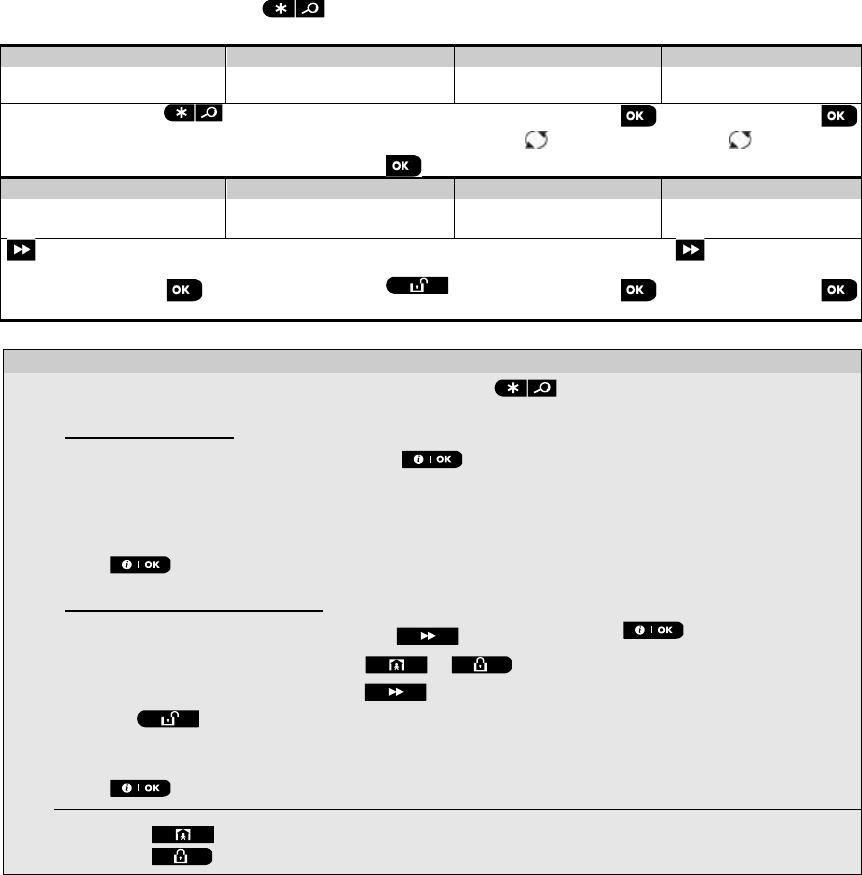
7. READING THE EVENT LOG
56 D-305735 PowerMaster 360 Installer's Guide
7. READING THE EVENT LOG
Up to 100 events are stored in the event log. You can access this log and review the events, one by one. If the event
log fills up completely, the oldest event is deleted upon registration of each new event. The date and time of occurrence
are memorized for each event.
Note: Up to 250 events are stored in the event log that can be reviewed via the Remote Programmer PC software
application or by the remote PowerManage server.
When reading the event log, events are shown in chronological order - from the newest to the oldest. Access to the
event log is provided by clicking the button and not through the Installer Mode menu. The reading and erasing
process of the event log is shown below.
Step 1
Step 2
Step 3
Step 4
In normal operating
mode [1] Enter Installer Code [2] Reviewing Events [3] Scroll List of Events [4]
READY 00:00
ENTER CODE:
Z13 alarm
SR2 TAMPER-ALARM
LIST OF EVENTS
09/02/11 3:37 P
07/02/11 11:49 a
Step 5
Step 6
Step 7
Step 8
CLEAR EVENT LOG
display
[5]
Erase the Event Log
[6]
Event Log is erased
[7]
Returns to normal
operating mode
[8]
➯
CLEAR EVENT LOG
<OFF> to delete
<OK> TO EXIT
READY 00:00
- Reading Events
[1] While the system is in the normal operating mode, press the key.
Reading the Event Log
[2] Enter the current Installer Code and then press to enter "LIST OF EVENTS".
[3] The latest event is shown.
The event is displayed in two parts, for example, "Z13 alarm" then "09/02/10 3:37 P".
Note: In Soak Test mode, the panel displays the alarmed zone and alternates with “Zxx:Soak T.Fail”.
[4] Press repeatedly to scroll through the list of events.
Erasing and Exiting the Event Log:
[5]
From anywhere within the event log, press the button and then press .
[6] At this stage in the procedure, clicking the or buttons will take you to “<OK> TO EXIT”
without erasing the event log. Clicking the button will revert to “CLEAR EVENT LOG”.
Press the button to erase the event log.
[7] The system erases the event log
[8] Press to revert to normal operating mode.
Clicking the button repeatedly at any stage in the procedure takes you one level up with each click.
Clicking the button will take you to “<OK> TO EXIT”.
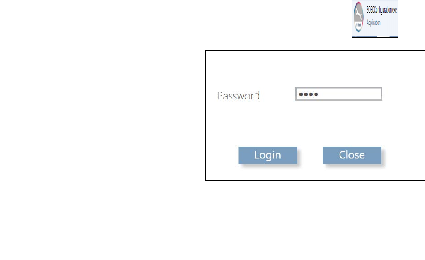
APPENDIX A. PowerMaster 360 Configurator
D-305735 PowerMaster 360 Installer's Guide 57
APPENDIX A. PowerMaster 360 Configurator
The PowerMaster 360 Configurator is the interface with the installed PowerMaster 360 security system. Installers and
home/property owners configure the Communication settings with the Central Monitoring Station. Installers configure
the system through the Configurator’s Virtual Keypad.
A1. Working with the PowerMaster Configurator
1. Connect the USB cable to the PowerMaster 360 and to the laptop.
Note: In some cases Windows will require manual installation of the USB driver. To perform this, follow the detailed
instructions in section A2.
When the PowerMaster 360 is ready, the LEDs conditions are as follows:
Power ON GREEN
Arming Status AWAY
HOME
DISARM
RED
RED BLINK
OFF
Troubles OFF no troubles; ON active troubles ORANGE
Connection ON: connected to PowerManage; OFF:
Ethernet cable disconnected; Router turned
OFF/disconnected; not connected to
PowerManage
BLUE
WiFi1 WiFi access point enabled GREEN
Back LEDs Initialization, enroll success / failure RED, GREEN and ORANGE
2. Download the PowerMaster 360 software from the CD.
3. Run the Configurator.exe file. The PowerMaster 360 icon appears on your desktop.
Note: A link to a USB driver is also added to your desktop.
4. Log in with the Password which is the download
code that is included with the PowerMaster 360
kit, and then click Login.
Note: It is recommended to use the default
password that initially appears on the screen.
After several seconds, the Configurator screen appears.
Note: If the Configurator does not allow login, or a USB driver error appears, use the USB driver link on your desktop to
install the USB driver. After performing the driver installation, try to login to the Configurator again.
1 Relevant when WiFi module is mounted
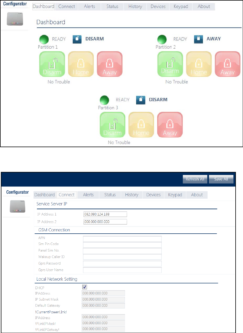
APPENDIX A. PowerMaster 360 Configurator
58 D-305735 PowerMaster 360 Installer's Guide
5. The Dashboard tab is used to gain quick access for performing basic arming and disarming of the alarm system. In
addition, the screen displays system status, assigned partitions and trouble indications.
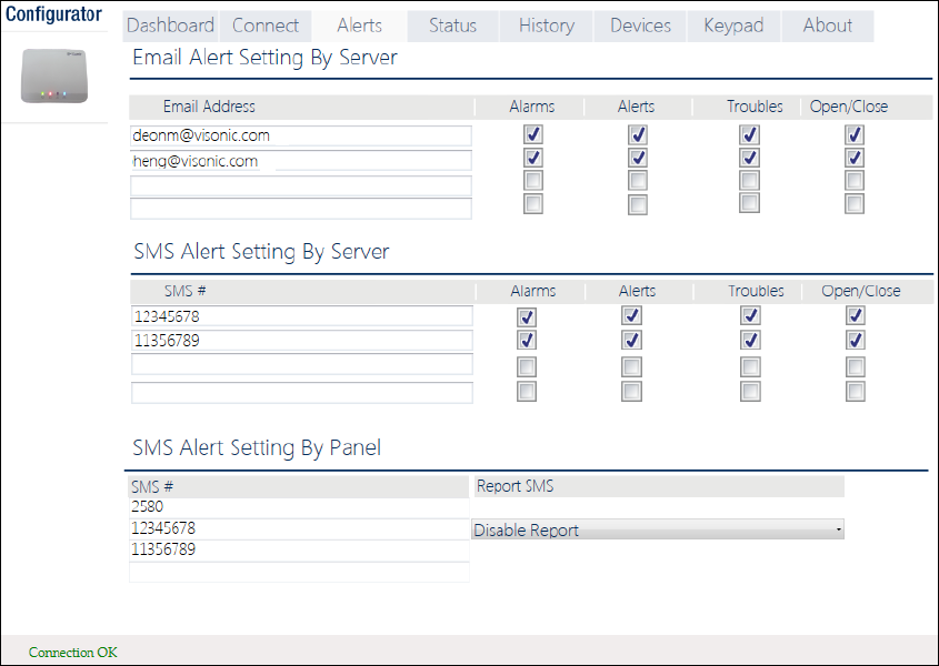
APPENDIX A. PowerMaster 360 Configurator
D-305735 PowerMaster 360 Installer's Guide 59
6. Click the Connect tab, which includes Broadband network settings. Enter the following settings:
o IP Address 1/2: First and second IP address of the PowerManage server with which the PowerMaster 360
communicates.
o APN: Enter the name of the Access Point used for the internet settings of the GSM.
o Sim Pin Code: Enter the PIN code of the SIM card installed in the GSM module.
o Panel Sim No: Enter the PowerMaster 360 SIM card telephone number.
o Wakeup Caller ID: Enter the "Caller ID" (i.e. telephone number) from which the Monitoring Station calls the
control panel for initiating the Up/Download process.
o GPRS Password / User Name: Enter the Password and Username of the APN used for GPRS communications
o Local Network Setting DHCP: Select this option to obtain the PowerMaster 360’s IP address automatically. To
assign the PowerMaster 360 a specific and permanent IP address, deselect this option and type its IP Address,
Subnet Mask and Gateway.
o Current PowerLink. Read only fields that display the current PowerLink IP addresses of the PowerMaster 360.
7. Click Save All in the top right corner of the screen.
Note: Save All saves all changes made on all of the Configurator tabs.
8. Click the Alerts tab. Here, define up to 4 email addresses and 4 mobile devices to receive forwarded events by e-
mail and SMS from the PowerManage server. Additionally, select the types of event messages which each user is
allowed to receive (Alarms, Alerts, Troubles, Open/Close events).
Notes for installers:
o Verify that the PowerManage server is configured to send emails and SMSs.
o Verify that the Panel event reporting to CMS is defined as ALL.
o Any of these notifications can be sent to the property owner in addition to the Central Monitoring Station. For
detailed instructions, see the PowerMaster 360 Installer and Quick Guide.
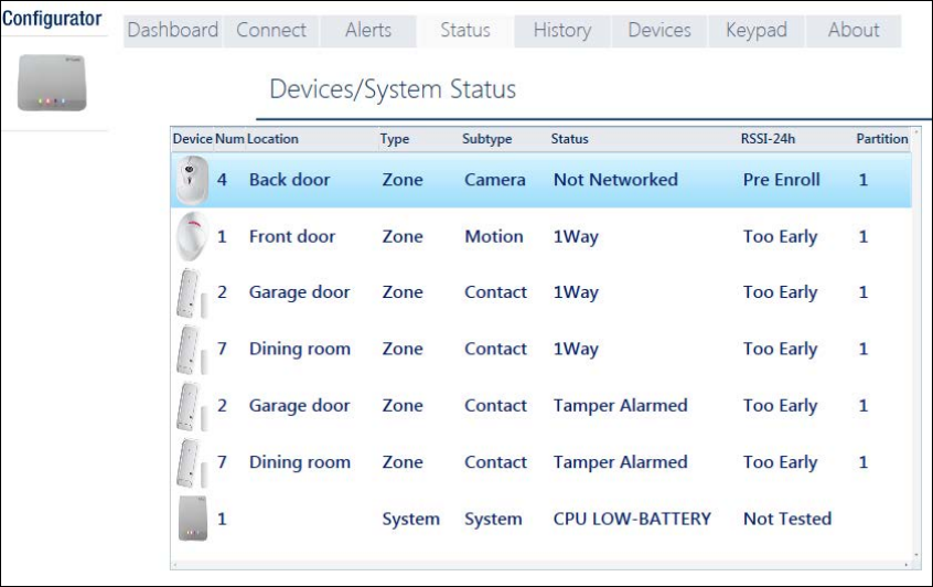
APPENDIX A. PowerMaster 360 Configurator
60 D-305735 PowerMaster 360 Installer's Guide
9. Click Save All.
10. Click the Status tab to review detected trouble conditions in any of the enrolled devices. The table displays the
device number, Location Name, Zone Type, Device Type, Trouble Status, Received Signal Strength Indication of the
last 24 hours and Partition numbers.
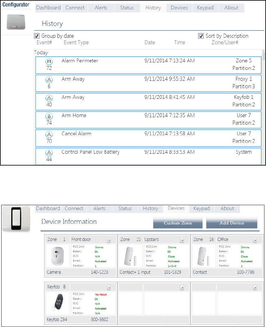
APPENDIX A. PowerMaster 360 Configurator
D-305735 PowerMaster 360 Installer's Guide 61
11. Click the History tab to review the events (up to 100) that the PowerMaster 360 control panel has detected. The
table includes: event number; type of event; date and time of event; and relevant zone/user number and partition
number. Select the “Group by date” or “Sort by Description” checkbox to display events according to event
description or in chronological order.
12. Click the Devices tab to review all pre-enrolled and enrolled (activated) devices, open/close state of detectors,
received signal strength indication of the last 24 hours and battery status of devices. In addition, you can review and
change the location of devices and delete devices.
The “Custom Zone” and “Add Device” buttons allow you to define custom location names and pre-enroll devices.
13. Click Save All after defining custom locations and pre-enrolling devices.
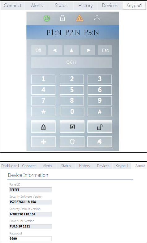
APPENDIX A. PowerMaster 360 Configurator
62 D-305735 PowerMaster 360 Installer's Guide
14. Click the Keypad tab to display the
PowerMaster 360’s Virtual Keypad. The
Virtual Keypad enables access to the full
USER MODE and INSTALLER MODE panel
features. Use this keypad to perform all
system setup and programming functions
(for detailed instructions, see the
PowerMaster 360 Installer and Quick
Guide).
The Virtual Keypad supports voice
prompts. To hear the prompts, adjust your
PC’s speaker volume.
15. The About tab displays the PowerMaster
360’s serial number (Panel ID), its firmware
versions and PowerLink version. In addition,
here, you can review or change the
Password used to gain access to
PowerMaster 360 Installer Mode Menu.
16. Click Save All after changing Password.
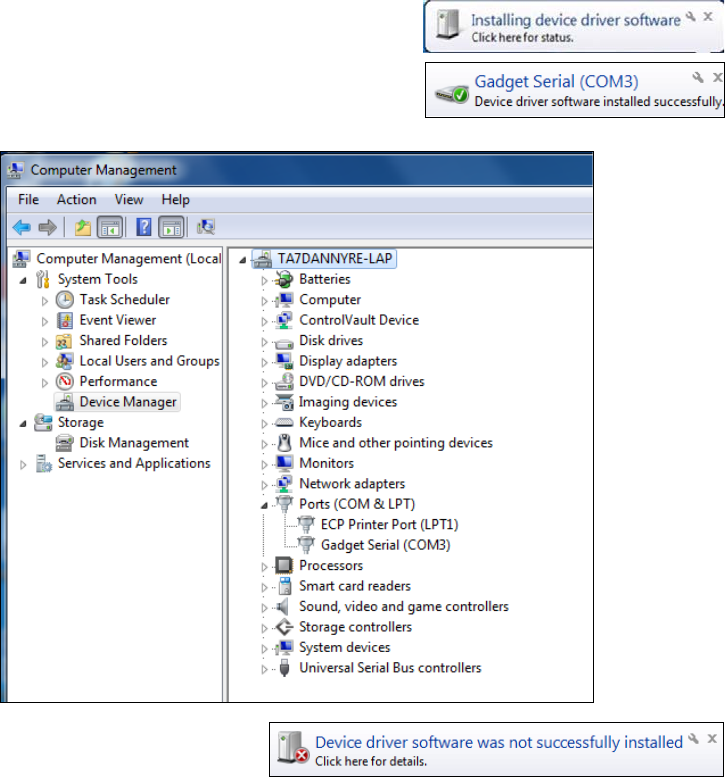
APPENDIX A. PowerMaster 360 Configurator
D-305735 PowerMaster 360 Installer's Guide 63
A2. Manually Installing the USB Driver
1. Connect the USB cable to the PowerMaster 360 and to the laptop;
the following message will appear in the bottom right corner of the
screen.
2. If installation is successful, the following message will appear.
The screen below then opens.
Note: ELMO GMAS (COMxx) may appear instead of Gadget
Serial (COMxx) in both this message and in the screen below.
3. If Windows does not recognize the software
during startup, the following message will
appear:
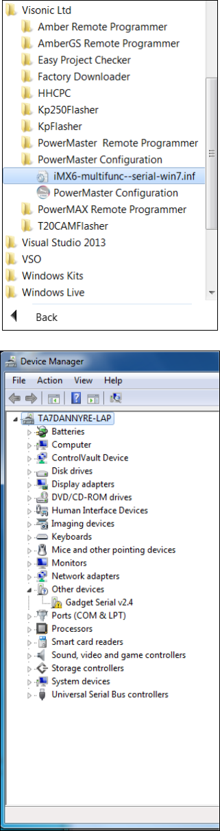
APPENDIX A. PowerMaster 360 Configurator
64 D-305735 PowerMaster 360 Installer's Guide
4. In this case navigate to Start
→
All Programs
→
Visonic Ltd and save the “iMX6-multifunc- -serial-
win7.inf” file to a temporary folder. For example,
T:/iMX6_Driver.
5. Navigate to the Other devices folder.
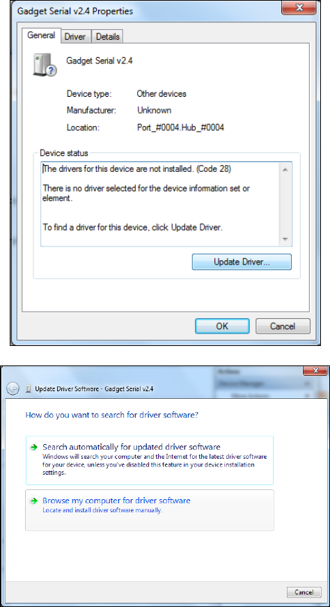
APPENDIX A. PowerMaster 360 Configurator
D-305735 PowerMaster 360 Installer's Guide 65
6. Right-click the Gadget Serial vx.x file
and then select Properties; the
following screen appears.
7. In the General tab, click the Update
Driver… button; the screen below
appears.
8. Select the Browse my computer for
driver software option.
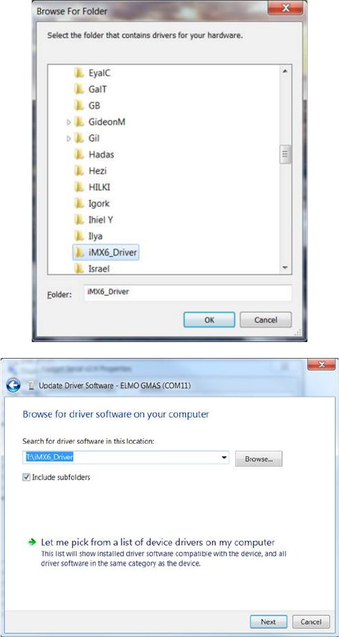
APPENDIX A. PowerMaster 360 Configurator
66 D-305735 PowerMaster 360 Installer's Guide
9. In the screen that opens, click Browse
and then navigate to the temporary
folder where the “iMX6-multifunc- -
serial-win7.inf” file was saved.
10. Select the folder and then click OK.
11. In the screen that opens, click Next.
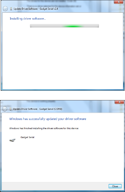
APPENDIX A. PowerMaster 360 Configurator
D-305735 PowerMaster 360 Installer's Guide 67
12. Windows now installs the driver
software.
13. When Windows has successfully
installed the driver software, the
following screen will appear.
14. Click Close.
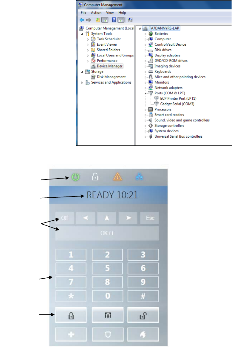
APPENDIX A. PowerMaster 360 Configurator
68 D-305735 PowerMaster 360 Installer's Guide
15. After concluding the procedure,
the Gadget Serial (COMxx) port
will appear on the right side of the
following screen.
A3. Virtual Keypad Controls
Virtual Keypad
Display
Control Keys
Keypad
Arming Keys
LED Icons
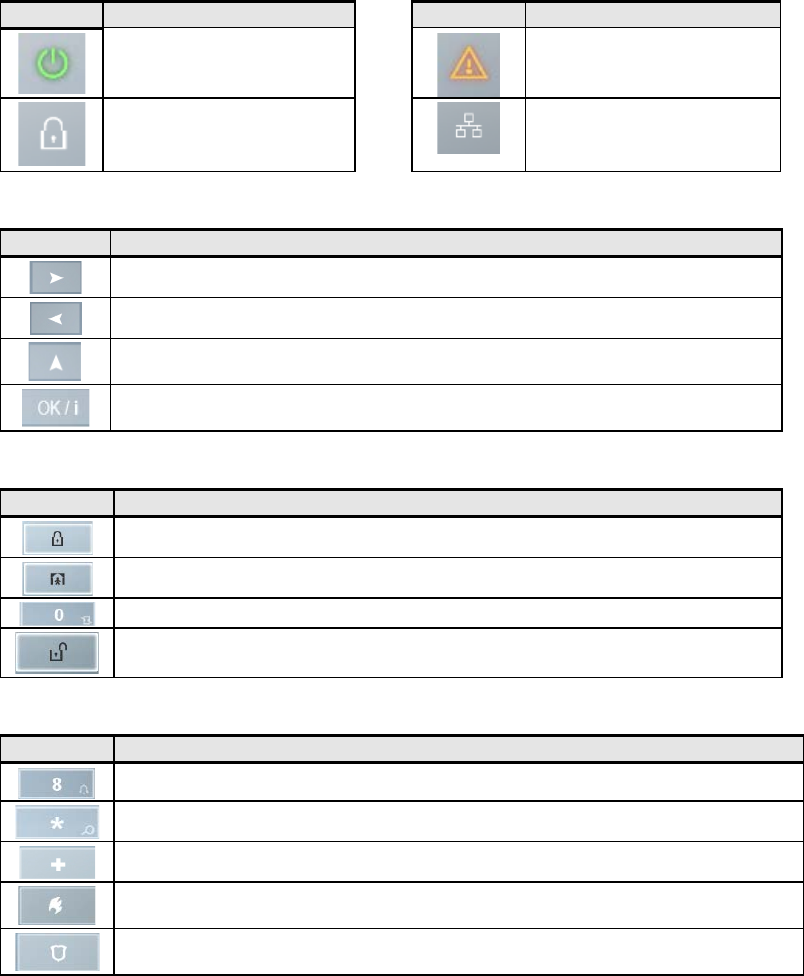
APPENDIX A. PowerMaster 360 Configurator
D-305735 PowerMaster 360 Installer's Guide 69
LED Icons
Indication
Function
Indication
Power
Trouble
Armed
AWAY – LED lights steadily.
HOME – LED blinks
Active service to the server
Control Keys
Indication
Function
NEXT:
Advance from item to item within a given menu.
BACK: Move one step back within a given menu.
UP: Use to move one level up in the menu or to return to previous setting step.
OK:
Review status messages one by one and also select a displayed option.
Arming Keys
Indication
Function
AWAY:
Arming when nobody is at home
HOME: Arming when people remain at home.
INSTANT: Canceling the entry delay upon arming (AWAY or HOME)
DISARM / OFF: Disarming the system and stopping alarms
Other Keys
Indication
Function
Chime ON/OFF
Reviewing the event log
Emergency
Fire
Panic
Note: The above buttons are identical in function to the corresponding buttons shown throughout the document.

APPENDIX B. VISONIConfig Mobile Installer App. For PowerMaster 360
70 D-305735 PowerMaster 360 Installer's Guide
APPENDIX B. VISONIConfig Mobile Installer App. For
PowerMaster 360
B1. Working with the PowerMaster Configurator
The PowerMaster 360 VISONIConfig Mobile Application is used by installers to configure the PowerMaster 360
security system and provides an easy-to-use virtual keypad that allows you to fully control the panel configurations.
Note: The Mobile Application operates on Android devices only.
1. Install the VISONIConfig Application; the VISONIConfig Application’s icon will appear on
your desktop.
2. Click the icon to launch the application. The Welcome screen will shortly appear on your
Android device screen.
3. Connect the USB cable to your Android device and to
the micro USB connection of the PowerMaster 360
panel.
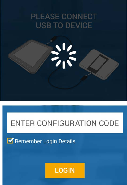
APPENDIX B. VISONIConfig Mobile Installer App. For PowerMaster 360
D-305735 PowerMaster 360 Installer's Guide 71
4. During the initialization process, the
following screen will appear.
5. After connection to the device has been
established, enter the Configurator Code
in the ENTER CONFIGURATION CODE
box.
6. Click the LOGIN button.
Notes:
• Select the Remember Login Details
checkbox to remember the typed in
Password for the next login.
• If the authentication process fails, an
error message will appear. Disconnect
the cable and then reconnect it.
• If you enter an incorrect Configuration
Code, you will receive an invalid code
message. Re-enter the code.
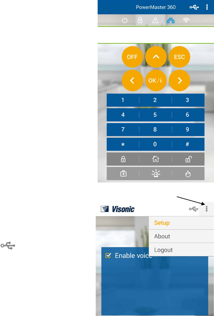
APPENDIX B. VISONIConfig Mobile Installer App. For PowerMaster 360
72 D-305735 PowerMaster 360 Installer's Guide
7. If the Configuration Code was entered correctly,
the Virtual Keypad appears. The Virtual Keypad
enables access to the full USER MODE and
INSTALLER MODE panel features. Use this
keypad to perform all system setup and
programming functions (for detailed instructions,
see the PowerMaster 360 Installer and Quick
Guide).
8. Click the drop-menu list button on the top right
of the screen; the following options appear:
• Setup: Click the radio button to enable /
disable the Virtual Keypad’s beeps.
• About: Displays the Application version.
• Logout: Click to Logout.
Note: The icon indicates one of the
following:
o Green – successful USB connection
o Gray – USB connection failure.
Drop
menu list
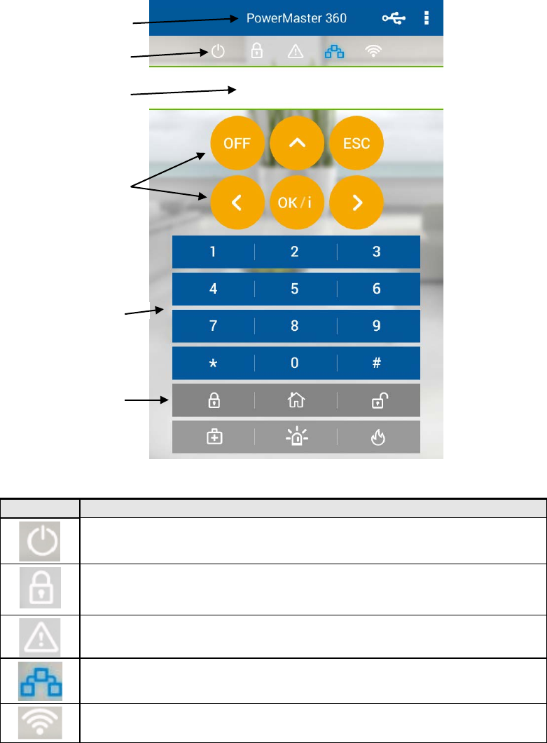
APPENDIX B. VISONIConfig Mobile Installer App. For PowerMaster 360
D-305735 PowerMaster 360 Installer's Guide 73
B2. VISONIConfig Controls
LED Icons
Indication
Function
Power
Armed
AWAY – LED lights steadily.
HOME – LED blinks
Trouble
Active service to the server
WiFi connection
Display
Product Name
Control Keys
Keypad
Arming Keys
LED Icons
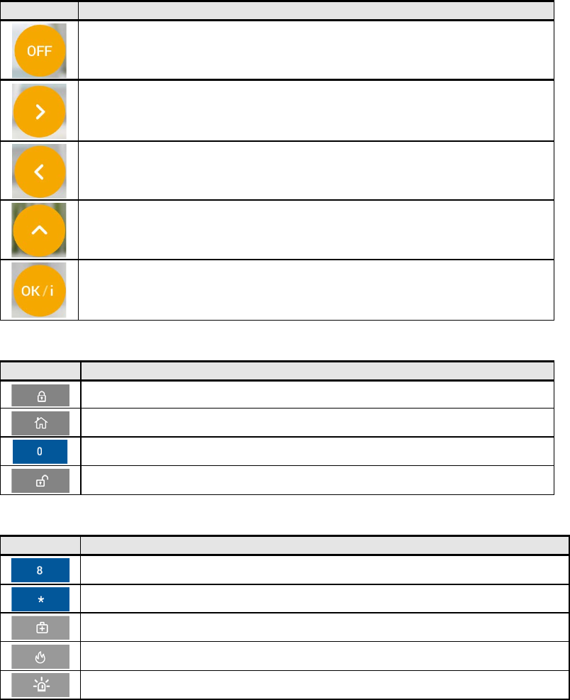
APPENDIX B. VISONIConfig Mobile Installer App. For PowerMaster 360
74 D-305735 PowerMaster 360 Installer's Guide
Control Keys
Indication
Function
OFF: Delete a device
NEXT: Advance from item to item within a given menu.
BACK: Move one step back within a given menu.
UP: Use to move one level up in the menu or to return to previous setting step.
OK: Review status messages one by one and also select a displayed option.
Arming Keys
Indication
Function
AWAY: Arming when nobody is at home
HOME: Arming when people remain at home.
INSTANT: Canceling the entry delay upon arming (AWAY or HOME)
DISARM / OFF: Disarming the system and stopping alarms
Other Keys
Indication
Function
Chime ON/OFF
Reviewing the event log
Emergency
Fire
Panic
Note: The above buttons are identical in function to the corresponding buttons shown throughout the document.
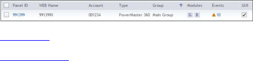
APPENDIX C. User Mobile Application with PowerMaster 360
D-305735 PowerMaster 360 Installer's Guide 75
APPENDIX C. User Mobile Application with
PowerMaster 360
C1. Security Only Via PowerManage
After establishing connection with the PowerManage server, the PowerMaster 360 appears as an entry in the
PowerManage Panel List. The WEB Name is retrieved from the PowerMaster 360’s Panel ID.
The home/property owner can access the PowerMaster 360 security system on a mobile device using the
PowerManage Interactive app (for arming/disarming, viewing event details, etc.). The system’s URL is
https://[PowerManage server IP address]/[Panel’s WEB Name].
For example: with a PowerManage on IP 100.101.102.103 using HTTPS communication and a panel with Panel_ID
140613. The link to this panel’s web portal will be:
https://100.101.102.103/140613
C2. Security and Smart Home Via 3rd Party
The home/property owner can access the PowerMaster 360 security and smart home system on a mobile device using
a 3rd Party app (for arming/disarming and switching on/off lights, A/C, etc.).

APPENDIX D. Specifications
76 D-305735 PowerMaster 360 Installer's Guide
APPENDIX D. Specifications
D1. Functional
Zones Number
16 wireless zones.
Installer and User Codes
•
1 master installer (9999 by default)*
• 1 installer (8888 by default)*
• 1 master user, no. 1 (1111 by default)
• Users nos. 2 – 8
• Latchkey users 5 - 8
* Codes must not be identical
Control Facilities
Virtual keypad, wireless keyfobs and keypads
Arming Modes
AWAY, HOME, AWAY-INSTANT, HOME-INSTANT, FORCED, BYPASS.
Alarm Types
Silent, personal panic/emergency, burglary, gas (CO), and fire.
External Siren (bell) Timeout
Programmable (4 min. by default)
Supervision
Programmable time frame for inactivity alert
Special Functions
- Chime zones
- Diagnostic test and event log.
- Local and Remote Programming over Broadband and GPRS IP connections.
- Calling for help by using an emergency transmitter.
- Tracking inactivity of people.
Data Retrieval
Alarm memory, trouble, event log
Real Time Clock (RTC)
The control panel keeps and displays time and date. This feature is also used for the
log file by providing the date and time of each event
Battery Test
Once every 10 seconds
PowerG Receiver Range
160 ft. (50 m) internal, 6500 ft. (2000 m) external
Connectors
External:
• DC Power Jack
• RJ-45 Ethernet Connector
• Micro USB Connector
Internal:
• SIM Card Slot (part of GPRS Module)
• Micro SD Card Slot
• Battery Backup Connector
D2. Wireless
RF Network
PowerG – 2-way synchronized Frequency Hopping (TDMA / FHSS)
Frequency bands (MHz)
433 – 434
868 - 869
912 – 919
Hopping frequencies
8
4
50
Region
Worldwide
Europe
North America and
selected countries
Encryption
AES-128
GSM (MHz)
2G Band
3G Band
850, 900, 1800, 1900
850
1
, 900
2
, 1900
1
, 2100
2
Z-Wave (MHz) (optional)
868.4, 908.4, 921.4
WiFi - optional
2.4 GHz. Access Point is for IP camera support only
1 Covered by Module 2
2 Covered by Module 1

APPENDIX D. Specifications
D-305735 PowerMaster 360 Installer's Guide 77
D3. Electrical
External AC/DC adaptor
Input: AC 100-240V, 50/60 Hz, 0.55A
Output: 5 VDC, 2000 mA, 10W Max.
Current Drain
Approx. 200 mA standby, 1200 mA peak at full load.
Low Battery Threshold
3.8 V
Backup Battery Pack
3.7 V, 1000 mAh LIPO
Backup Battery Time
4 Hrs
Time to Charge
80 % (∼ 2 Hrs)
D4. Communication
Communication
IP, Ethernet 10/100
Monitoring Station Report
2 via PowerManage on IP and/or GPRS
Private Notifications
4 emails, 4 SMS numbers
Local Management Protocol to
Windows PC and Android Mobile
USB
Report Destinations
2 Monitoring Stations, 4 private SMS telephones via the server and 4 emails
Reporting Format Options
SIA, Contact ID, SIA IP
D5. Physical Properties
Operating Temp. Range
32°F to 120°F (0°C to 49°C)
Storage Temp. Range
50°F to 122°F (10°C to 50°C)
Humidity
93% relative humidity, @ 30°C (86°F)
Size
158x114.5x36.5 mm (6.22x4.5x1.43 in.)
Weight
225g (8 Oz)
Color
White
D6. Peripherals and Accessory Devices
Modules – factory default (SKU)
Base (default): IP and PowerG
GSM: 2G or 3G
WiFi: 2.4 GHz
Z-Wave: 500 Series
Additional wireless devices
16 detectors (includes 5 PIR cameras), 8 keyfobs, , 4 keypads, 2 wireless
sirens (internal/external), 1 repeater
Wireless Devices and peripherals
Pendants: PB-101 PG2, PB-102 PG2
Magnetic Contact: MC-302 PG2, MC-302E PG2, MC-302EL PG2, MC-302V
PG2
Motion Detectors: Next PG2; Next K9 PG2, TOWER-20 PG2, TOWER-32AM
PG2, TOWER-32AM K9 PG2, TOWER-30AM PG2, TOWER-30AM K9 PG2,
CLIP PG2, TOWER CAM PG2
PIR Camera Detectors: Next CAM PG2; Next CAM-K9 PG2
Smoke Detector: SMD-426 PG2, SMD-427 PG2
Keyfob: KF-234 PG2, KF-235 PG2
Keypad: KP-140 PG2/KP-141 PG2 (with proximity tag), KP-160 PG2
Indoor Siren: SR-720 PG2, SR-720B PG2
Outdoor Sirens: SR-730 PG2, SR-740 PG2, SR-740 HEX PG2
Repeater: RP-600 PG2
Gas: GSD-441 PG2, GSD-442 PG2 (CO detector)
Glass-break: GB-501 PG2
Temperature: TMD-560 PG2
Flood: FLD-550 PG2, FLD-551 PG2
Shock: SD-304 PG2

APPENDIX E. Working with Partitions
78 D-305735 PowerMaster 360 Installer's Guide
APPENDIX E. Working with Partitions
Your alarm system is equipped with an integrated partitioning feature that can divide your alarm system into three
distinct areas identified as Partition 1 through 3. A partition can be armed or disarmed regardless of the status of the
other partitions within the system. Partitioning can be used in installations where shared security systems are more
practical, such as a home office or warehouse building. When partitioned, each zone, each user code and many of your
system's features can be assigned to Partition 1 to 3. Each user code is assigned with the list of partitions it is allowed
to control in order to limit access of users to certain partitions.
When partitioning is enabled, menu displays are changed to incorporate the partition feature and also each device, user,
and proximity tag has additional partitions menu, where it is assigned to certain partitions and excluded from others.
Note: When Partition Mode is disabled, all zones, user codes, and features of the control panel will operate as in a
regular unit. When partition mode is enabled, all zones, user codes, and features of the control panel are
automatically assigned to Partition 1.
E1. User Interface and Operation
Refer to the control panel User's Guide APPENDIX B. PARTITIONING for a detailed description of the user interface
(Arming/Disarming, siren behavior, show function, etc.), and APPENDIX A for keyfobs and keypads operation in
Partition Mode.
E2. Common Areas
Common areas are areas used as walkthrough zones to areas of 2 or more partitions. There may be more than one
common area in an installation depending on the layout of the property. A common area is not the same as a partition;
it cannot be armed / disarmed directly. Common areas are created when you assign a zone or zones to 2 or 3
partitions. Table A1 summarizes the behavior of the different zone types in a common area.
Table A1 – Common Area Definitions
Common area zone types
Definition
Perimeter
• Acts as defined only after the last assigned partition is armed AWAY or HOME.
• In case that one of the partitions is disarmed, an alarm initiated from this zone is
ignored for all assigned partitions.
Delay zones • Delay zones will not trigger an entry delay unless all assigned partitions are armed.
It is, therefore, not recommended to define delay zones as common areas.
Perimeter follower
• Act as defined only after the last assigned partition is armed AWAY or HOME.
• In case that one of the partitions is disarmed, an alarm initiated from this zone is
ignored for all assigned partitions.
• In case that one of the common area assigned partitions is in a delay state (and
the other partitions are armed), the alarm will behave as a perimeter follower for
this partition only. The event will be ignored for other assigned armed partitions.
Interior • Acts as defined only after the last assigned partition is armed AWAY.
• In case that one of the partitions is disarmed or armed HOME, an alarm initiated
from this zone is ignored for all assigned partitions.
Interior follower • Acts as defined only after the last assigned partition is armed AWAY.
• In case that one of the partitions is disarmed or armed HOME, an alarm initiated
from this zone is ignored for all assigned partitions.
• In case that one of the common area assigned partitions is in a delay state (and
the other partitions are armed), the alarm will behave as an interior follower for this
partition only. The event will be ignored for other assigned armed partitions.
Home / Delay
• Acts as a Perimeter-Follower type when all assigned partitions are armed AWAY.
• Acts as a Delay type when at least one of the assigned partitions is armed HOME.
• Will be ignored when at least one of the assigned partitions is disarmed.
Emergency; Fire; Flood; Gas;
Temperature; 24-hour silent;
24-hour audible; Non-alarm
• Always armed.
Note: A Soak Test of Common areas cannot be initiated when one of its partitions is armed. When Soak Test of a
Common area is active, an alarm event is ignored unless all the partitions that are assigned to the zone are armed.

APPENDIX F. Detector Deployment & Transmitter Assignments
D-305735 PowerMaster 360 Installer's Guide 79
APPENDIX F. Detector Deployment & Transmitter
Assignments
F1. Detector Deployment Plan
Zone
Zone Type
Location
Chime (melody
Sensor
Holder
No.
Default
Programmed
Default
Programmed
Location) or Off (*)
Type
1
Exit/Entry 1
Front Door
2
Inter-Follow
Living Room
3
Exit/Entry 2
Attic
4
Perimeter
Back Door
5
Perimeter
Child Room
6
Inter-Follow
Office
7
Inter-Follow
Dining Room
8
Perimeter
Dining Room
9
Perimeter
Kitchen
10
Perimeter
Living Room
11
Inter-Follow
Living Room
12
Inter-Follow
Bedroom
13
Perimeter
Bedroom
14
Perimeter
Guest Room
15
Inter-Follow
Master Bedroom
16
Perimeter
Master Bedroom
Zone Types: 1 = Exit / Entry 1
2 = Exit / Entry 2
3 = Home Delay
4 = Interior Follower
5 = Interior
6 = Perimeter
7 = Perimeter Follower
8 = 24hr Silent
9 = 24hr Audible
10 = Emergency
11 = Arming Key
12 = Non-Alarm
17 = Guard
18 = Outdoor.
Zone Locations: Note down the intended location for each detector. When programming, you may select one of 31
custom locations – see "02:ZONES/DEVICES" menu).
Notes:
All zones are chime off by default. Enter your own choice in the last column and program accordingly.
F2. Keyfob Transmitter List
Transmitter Data
AUX button Assignments
No.
Type
Holder
No.
Type
Holder
Skip exit delay or Arming “instant”
1
17
Indicate the desired function (if any)
2
18
3
19
4
20
5
21
6
22
7
23
8
24
9
25
10
26
11
27
12
28
13
29
14
30
15
31
Skip exit delay
16
32
Arming “instant”

APPENDIX F. Detector Deployment & Transmitter Assignments
80 D-305735 PowerMaster 360 Installer's Guide
F3. Emergency Transmitter List
Tx #
Transmitter Type
Enrolled to Zone
Name of holder
1
2
3
4
5
6
7
8
9
10
F4. Non-Alarm Transmitter List
Tx #
Transmitter Type
Enrolled to Zone
Name of holder
Assignment
1
2
3
4
5
6
7
8
9
10

APPENDIX G. Event Codes
D-305735 PowerMaster 360 Installer's Guide 81
APPENDIX G. Event Codes
G1. Contact ID Event Codes
Code
Definition
Code
Definition
101
Emergency
110
Fire
351
Telco fault
114
Heat
373
Fire detector trouble
120
Panic
374
Exit error alarm (zone)
121
Duress
350
Communication trouble
122
Silent
380
Sensor trouble
123
Audible
381
Inactive event
129
Confirm panic
383
Sensor tamper
131
Perimeter
384
RF low battery
132
Interior
389
Sensor self-test failure
133
24 Hour (Safe)
391
Sensor Watch trouble
134
Entry/Exit
393
Fire detector clean me
137
Tamper/CP
401
O/C by user
139
Burglary verified
403
Auto arm
140
General alarm
406
Cancel
151
Gas alarm
408
Quick arm
152
Freezer alert
412
Successful download/access
153
Freeze alert
426
Door open event
154
Flood alarm
441
Armed home
158
High temperature
454
Fail to arm
159
Low temperature
455
Autoarm failed
180
Gas trouble
456
Partial arm
220
Guard sensor alarmed
459
Recent close event
301
AC loss
570
Bypass
302
Low system battery
602
Periodic test report
311
Battery disconnect
607
Walk test mode
313
Engineer reset
625
Time/Date change
321
Fuse
627
Program mode entry
333
Expansion modem failure
628
Program mode exit
344
RF receiver jam detect
641
Senior watch trouble
G2. SIA Event Codes
Code
Definition
Code
Definition
AR
AC Restore
LT
Phone Line Trouble
AT
AC Trouble
LX
Local Programming Ended
BA
Burglary Alarm
OP
Opening Report
BB
Burglary Bypass
OT
Fail to Arm
BC
Burglary Cancel
PA
Panic Alarm
BJ
Burglary Trouble Restore
PR
Panic Restore
BR
Burglary Restore
QA
Emergency Alarm
BT
Burglary Trouble / Jamming
RN
Engineer Reset
BV
Burglary Verified
RP
Automatic Test
BX
Burglary test
RS
Remote Program Success
BZ
Inactive event
RX
Manual Test
CF
Forced Closing
RY
Exit from Manual Test
CG
Armed home
TA
Tamper Alarm
CI
Fail to Close
TE
Communicator restored to operation
CL
Armed Away
TR
Tamper Restore
CP
Auto Arm
TS
Communicator taken out of operation
CR
Recent Close
UJ
Detector mask restore
EA
Door Open
UT
Detector mask
FA
Fire Alarm
WA
Flood alarm
FJ
Fire detector trouble
WR
Flood alarm restore
FR
Fire Restore
XR
Sensor Battery Restore
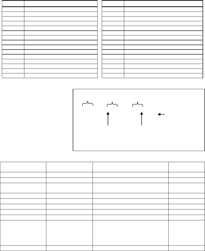
APPENDIX G. Event Codes
82 D-305735 PowerMaster 360 Installer's Guide
Code
Definition
Code
Definition
FT
Fire Detector Clean
XT
Sensor Battery Trouble
FX
Fire test
YA
Fuse Fault
GA
Gas alarm
YH
Bell Restored
GJ
Gas trouble restore
YI
Overcurrent Trouble
GR
Gas alarm restore
YM
System battery disconnect
GT
Gas trouble
YR
System Battery Restore
GX
Gas test
YT
System Battery Trouble / Disconnection
HA
Holdup Alarm (duress)
YX
Service Required
JT
Time Changed
YZ
Service Completed
KA
Heat alarm
ZA
Freeze alert
KH
Heat alarm restore
ZH
Freeze alert restore
KJ
Heat trouble restore
ZJ
Freezer alert restore
KT
Heat trouble
LB
Local Program
ZT
Freezer alert
LR
Phone Line Restore
G3. Understanding the Scancom Reporting Protocol Data Format
The SCANCOM data format consists of
13 decimal digits divided into 4 groups,
from left to right, as shown on the right.
Each channel is associated with a
specific event as follows:
1st "C": Fire
2nd "C": Personal attack
3rd "C": Intruder
4th "C": Open/close
5th "C": Alarm cancel
6th "C": Emergency
7th "C": Second alarm
8
th
"C": Trouble messages
Account
Code
aaaa
Channels
1 - 4
cccc
Channels
5 - 8
cccc
S
System Status:
no trouble, test,
low battery
- - - - - - - -
The digit in this position
conveys the status of
channel 1
The digit in this position
conveys the status of
channel 8
Scancom Data Format
G4. SIA over IP - Offset for Device User
Type Number Range In
decimal
Example Remarks
System reports
00
System tamper would report as 000
Normal Zones/Detectors
1-499
Zone 5 would report as 005
Keyfobs / Users /Tags
501-649
Keyfob/User number 101 would report
601
Pendants
651-699
Pendant number 1 would report 651
Keypads/ASU
701-799
Keypad number 8 would report 708
Sirens
801-825
Siren number 9 would report 809
Repeaters
831-850
Repeater number 4 would report 834
Expanders/Bus devices
851-875
Device number 2 would report 852
Troubles for:
GSM
BBA
Plink
Guard
876
877
878
879
GSM module network fail 876
BBA bus trouble 877
901- 999
For future use
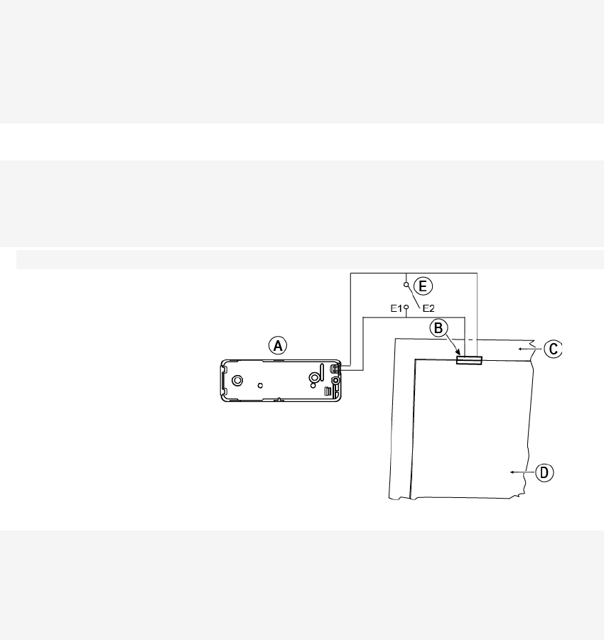
APPENDIX H. Sabbath Mode
D-305735 PowerMaster 360 Installer's Guide 83
APPENDIX H. Sabbath Mode
H1. General Guidance
The Sabbath Mode allows you to use the alarm system without violating the Sabbath. The basic feature of this alarm
system is that the PIR sensors are not activated during Disarm mode.
The method of installation, as illustrated in the drawing below, is used in order to prevent transmission from the
magnetic contact device. The MC-302E device is used only as a transmitting device to report the status of the door to
the control panel. A wired magnetic contact is connected to the input of the MC-302E device and an open/close switch
is connected in parallel to the MC-302E input.
Note: Before the Sabbath, closing the circuit neutralizes the detector’s magnet. You can use the front door without
violating the Sabbath. On the Sabbath day itself, you can open the switch to allow the door to be protected. This
operation is permitted on the Sabbath and also when the control panel is armed.
H2. Connection
1. Enroll an MC-302E to the PowerMaster 360 control panel (see section 4.4.2).
2. Configure the “Input #1” setting option of the MC-302E to “Normally Closed” (refer to the MC-302E Installation
Instructions, section 2.3).
3. Connect to the MC-302E a wired magnetic contact to be installed on the door and that is operated by
opening/closing the door (see drawing below).
4. An open/close switch must be connected in parallel to the input of the MC-302E.
Wiring Setup
A. MC-302E device
B. Wired magnetic contact
C. Fixed frame
D. Moving part
E. Open/close switch
E1. Closed
E2. Open
H3. Arming the System by Sabbath Clock
1. Enroll an MC-302E to the PowerMaster 360 control panel (see section 4.4.2).
2. Configure the Zone Type to “11.Arming Key” (see section 4.4.2)
3. Configure the “Input #1” setting option of the MC-302E to “Normally Open” (refer to the MC-302E Installation
Instructions, section 2.3).
4. From the “03:CONTROL PANEL” menu, configure the “09:ARMING KEY” setting option to “arm HOME” (see
section 4.5.2).
Note: When the alarm system is armed at night by a Sabbath clock, the open / close switch must be opened when the
door is closed.

APPENDIX I. Glossary
84 D-305735 PowerMaster 360 Installer's Guide
APPENDIX I. Glossary
Abort Period: When an alarm is initiated, the internal sounder is activated first for a limited period of time which is the
abort period set by the installer. If you cause an alarm accidentally, you can disarm the system within the abort period
before the real sirens start and before the alarm is reported to the remote responders.
Alarm: There are 2 kinds of alarms:
Loud alarm - the external siren blares out constantly and the control panel reports the event.
Silent alarm - the sirens remain silent, but the control panel reports the event.
A state of alarm is caused by:
• Motion detected by a motion detector (when the system is in the Armed state)
• Change of state detected by a magnetic contact detector - a closed window or door is opened
• Detection of smoke by a smoke detector, detection of gas by a gas detector and detection of water based fluids by
a flood detector (when in any state).
• Tampering with any one of the detectors
Arming: Arming the alarm system is an action that prepares it to sound an alarm if a zone is “violated” by motion or by
opening a door or window, as the case may be. The control panel may be armed in various modes (see AWAY, HOME,
INSTANT and LATCHKEY).
Assigned: Refers to zones.
Associated: Refers to devices.
AWAY: This type of arming is used when the protected site is vacated entirely. All zones, interior and perimeter alike,
are protected.
Chime Zones: Allow you to keep track of activity in the protected area while the alarm system is in the disarmed state.
Whenever a chime zone is "opened", the buzzer beeps twice via the Configuration device (PC or mobile). The buzzer
does not beep, however, upon closing the zone (return to normal). Residences can use this feature to annunciate
visitors or look after children. Businesses can use it to signal when customers enter the premises or when personnel
enter restricted areas.
Note: Your installer will never designate a 24-hour zone or a fire zone as a chime zone, because both zone types
actuate an alarm if disturbed while the system is in the disarmed state.
Although one zone or more are designated as chime zones, you can still enable or disable the chime function.
Communicators: Refers to communication channel, for example, GSM.
Control Panel: The control panel is a cabinet that incorporates the electronic circuitry and microprocessor that control
the alarm system. It collects information from various sensors, processes it and responds in various ways. It also
includes the user-interface - control keys, numerical keypad, display, sounder and loudspeaker.
Default Settings: Settings that are applicable to a specific device group.
Detector: The device (apparatus) that sends an alarm, that communicates with the control panel (for example,
Next PG2 is a motion detector; SMD-426 PG2 is a smoke detector).
Disarming: The opposite of arming - an action that restores the control panel to the normal standby state. In this state,
only fire and 24-hour zones will sound an alarm if violated, but a “panic alarm” may also be initiated.
Disturbed Zone: A zone in a state of alarm (this may be caused by an open window or door or by motion in the field of
view of a motion detector). A disturbed zone is considered “not secured”.
Forced Arming: When any one of the system zones is disturbed (open), the alarm system cannot be armed. One way
to solve this problem is to find and eliminate the cause for zone disturbance (closing doors and windows). Another way
to deal with this is to impose forced arming - automatic de-activation of zones that are still disturbed upon termination
of the exit delay. Bypassed zones will not be protected throughout the arming period. Even if restored to normal
(closed), bypassed zones will remain unprotected until the system is disarmed.
Permission to “force arm” is given or denied by the installer while programming the system.
HOME: This type of arming is used when people are present within the protected site. A classic example is night-time
at home, when the family is about to retire to bed. With HOME arming, perimeter zones are protected but interior zones
are not. Consequently, motion within interior zones will be ignored by the control panel, but disturbance of a perimeter
zone will cause an alarm.
Instant: You can arm the system AWAY-INSTANT or HOME-INSTANT, thereby canceling the entry delay for all delay
zones for the duration of one arming period.
For example, you may arm the control panel in the HOME-INSTANT mode and remain within the protected area. Only
perimeter protection is active, and if you do not expect somebody to drop in while the system is armed, alarm upon
entry via the main door is an advantage.
To disarm the system without causing an alarm, use your control keypad (which is normally accessible without
disturbing a perimeter zone) or use a keyfob transmitter.
Latchkey: The Latchkey mode is a special arming mode in which designated "latchkey users" will trigger a "latchkey
message" to be sent to a telephone when they disarm the system.
For example, if a parent wants to be sure that their child has returned from school and disarmed the system. Latchkey
arming is only possible when the system is armed in the AWAY mode.

APPENDIX I. Glossary
D-305735 PowerMaster 360 Installer's Guide 85
Location: Assigning a named location to a device (for example, Garage, Front Door etc.)
Magnetic Contact Detector, Wireless: A Magnet- controlled switch and a wireless PowerG transmitter in a shared
housing. The detector is mounted on doors and windows to detect changes in state (from closed to open and vice
versa). Upon sensing that a door or window is open, the detector transmits its unique identification code accompanied
by an “alarm” signal and various other status signals to the control panel.
The control panel, if not armed at that time, will consider the alarm system as “not ready for arming” until it receives a
“restored” signal from the same detector.
Motion Detector, Wireless: A passive Infrared motion sensor and a wireless PowerG transmitter in a shared housing.
Upon sensing motion, the detector transmits its unique identification code, accompanied by an alarm signal and various
other status signals to the control panel. After transmission, it stands by to sense further motion.
Non-Alarm Zone: Your installer can designate a zone for roles other than alarm. For instance, a motion detector
installed in a dark stairway may be used to switch on lights automatically when someone crosses the dark area.
Another example is a wireless transmitter linked to a zone that controls a gate opening mechanism.
Quick Arming: Arming without a user code. The control panel does not request your user code when you press one of the
arming buttons. Permission to use this arming method is given or denied by the installer while programming the system.
Remote Responder: A responder can be either a professional service provider to which the home or business owner
subscribes (a Monitoring Station) or a family relation/friend who agrees to look after the protected site during absence
of its occupants. The control panel reports events by telephone to both kinds of responders.
Restore: When a detector reverts from the state of alarm to the normal standby state, it is said to have been “restored”.
A motion detector restores automatically after detection of movement, and becomes ready to detect again. This kind of
“restore” is not reported to the remote responders.
A magnetic contact detector restores only upon closure of the protected door or window. This kind of “restore” is
reported to the remote responders.
Sensor: The sensing element: pyroelectric sensor, photo-diode, microphone, smoke optical sensor etc.
Signal Strength: The quality link communication between the system components and the control panel.
Smoke Detector, Wireless: A regular smoke detector and a wireless PowerG transmitter in a shared housing. Upon
detection of smoke, the detector transmits its unique identification code accompanied by an alarm signal and various
status signals to the control panel. Since the smoke detector is linked to a special fire zone, a fire alarm is initiated.
State: AWAY, HOME, AWAY-INSTANT, HOME-INSTANT, LATCHKEY, FORCED, BYPASS.
Status: AC fail, low battery, trouble, etc.
User Codes: The PowerMaster 360 is designed to obey your commands, provided that they are preceded by a valid
security access code.
Unauthorized people do not know this code, so any attempt on their part to disarm or defeat the system is bound to fail.
Some operations, however, can be carried out without a user code as they do not degrade the security level of the
alarm system.
Virtual Keypad: Contains the user-interface - control keys, numerical keypad and display.
Zone: A zone is an area within the protected site under supervision of a specific detector. During programming, the
installer allows the control panel to learn the detector’s identity code and links it to the desired zone. Since the zone is
distinguished by number and name, the control panel can report the zone status to the user and register in its memory
all the events reported by the zone detector. Instant and delay zones are “on watch” only when the control panel is
armed, and other (24-hour) zones are “on watch” regardless of whether the system is armed or not.
Zone Type: The zone type determines how the system handles alarms and other signals sent from the device.

APPENDIX J. Compliance with Standards
86 D-305735 PowerMaster 360 Installer's Guide
APPENDIX J. Compliance with Standards
Compliance with
Standards
Hereby, Visonic Group declares that the PowerG series of central units and accessories are designed to
comply with:
• U.S. Standards: (FCC) CFR 47 part 15
• Canada Standards: RSS 210
• European CE Standards: EN 300220, EN 300328, EN 301489, EN 50130-4, EN 60950
The PowerMaster 360 complies with the RTTE requirements - Directive 1999/5/EC of the European Parliament
and of the Council of 9 March 1999.
WARNING! Changes or modifications to this unit not expressly approved by the party responsible for compliance (Visonic Ltd.) could void the user’s
authority to operate the equipment.
This device complies with FCC Rules Part 15 and with Industry Canada licence-exempt RSS standard(s). Operation is subject to two conditions: (1) This
device may not cause harmful interference, and (2) this device must accept any interference that may be received or that may cause undesired operation.
Le présent appareil est conforme aux CNR d'Industrie Canada applicables aux appareils radio exempts de licence. L'exploitation est autorisée aux deux
conditions suivantes : (1) l'appareil ne doit pas produire de brouillage, et (2) l'utilisateur de l'appareil doit accepter tout brouillage radioélectrique subi, même si
le brouillage est susceptible d'en compromettre le fonctionnement.
NOTE: This equipment has been tested and found to comply with the limits for a Class B digital device, pursuant to part 15 of the FCC Rules. These limits
are designed to provide reasonable protection against harmful interference in a residential installation. This equipment generates, uses and can radiate radio
frequency energy and, if not installed and used in accordance with the instructions, may cause harmful interference to radio communications. However, there is
no guarantee that interference will not occur in a particular installation. If this equipment does cause harmful interference to radio or television reception, which
can be determined by turning the equipment off and on, the user is encouraged to try to correct the interference by one or more of the following measures:
-Reorient or relocate the receiving antenna.
-Increase the separation between the equipment and receiver.
-Connect the equipment into an outlet on a circuit different from that to which the receiver is connected.
-Consult the dealer or an experienced radio/TV technician for help.
Cet équipement a été testé et jugé conforme aux limites s’appliquant à un appareil numérique de classe B, conformément à la Partie 15 des réglementations
de la FCC. Ces limites ont été élaborées pour offrir une protection raisonnable contre les interferences nuisibles dans une installation résidentille.
Cet équipement génère, utilize et peut émettre de l’énergie de fréquence radio et, s’il n’est pas installé et utilize conformément aux instructions du fabricant,
peut provoquer des interférences dangereuses pour les communications radio. Toutefois, rien ne garantit l’absence d’interférences dans une installation
particuliére. Si cet équipement provoque des interférences nuisibles au niveau de la réception radio ou television, ce qui peut étre determine par la mise hors,
puis sous tension de l’équipment, vous étes invite à essayer de corriger les interferences en pregnant les mesures suivantes:
Réorientez ou déplaces l’antenne réceptrice.
Augmentez la distance qui sépare l’équipement et le récepteur.
Branchez l’équipement à une prise d’un circuit different de celui auquel est branché le récepteur.
Consultez le revendeur ou un technician radio/television expérimenté pour obtenir de l’aide.
Industry Canada Declaration
This product meets the applicable Industry Canada technical specifications/Le présent materiel est conforme aux specifications techniques appliables
d’Industrie Canada.

APPENDIX J. Compliance with Standards
D-305735 PowerMaster 360 Installer's Guide 87
WARRANTY
Visonic Limited (the “Manufacturer") warrants this product only (the "Product") to the original
purchaser only (the “Purchaser”) against defective workmanship and materials under normal
use of the Product for a period of twelve (12) months from the date of shipment by the
Manufacturer.
This Warranty is absolutely conditional upon the Product having been properly installed,
maintained and operated under conditions of normal use in accordance with the
Manufacturers recommended installation and operation instructions. Products which have
become defective for any other reason, according to the Manufacturers discretion, such as
improper installation, failure to follow recommended installation and operational instructions,
neglect, willful damage, misuse or vandalism, accidental damage, alteration or tampering, or
repair by anyone other than the manufacturer, are not covered by this Warranty.
The Manufacturer does not represent that this Product may not be compromised and/or
circumvented or that the Product will prevent any death and/or personal injury and/or damage
to property resulting from burglary, robbery, fire or otherwise, or that the Product will in all
cases provide adequate warning or protection. The Product, properly installed and
maintained, only reduces the risk of such events without warning and it is not a guarantee or
insurance that such events will not occur.
THIS WARRANTY IS EXCLUSIVE AND EXPRESSLY IN LIEU OF ALL OTHER
WARRANTIES, OBLIGATIONS OR LIABILITIES, WHETHER WRITTEN, ORAL, EXPRESS
OR IMPLIED, INCLUDING ANY WARRANTY OF MERCHANTABILITY OR FITNESS FOR
A PARTICULAR PURPOSE, OR OTHERWISE. IN
NO CASE SHALL THE
MANUFACTURER BE LIABLE TO ANYONE FOR ANY
CONSEQUENTIAL OR
INCIDENTAL DAMAGES FOR BREACH OF THIS WARRANTY OR ANY OTHER
WARRANTIES WHATSOEVER, AS AFORESAID.
THE MANUFACTURER SHALL IN NO EVENT BE LIABLE FOR ANY SPECIAL,
INDIRECT, INCIDENTAL, CONSEQUENTIAL OR PUNITIVE DAMAGES OR FOR LOSS,
DAMAGE, OR EXPENSE, INCLUDING LOSS OF USE, PROFITS, REVENUE, OR
GOODWILL, DIRECTLY OR INDIRECTLY ARISING FROM PURCHASER’S USE OR
INABILITY TO USE THE PRODUCT, OR FOR LOSS OR DESTRUCTION OF OTHER
PROPERTY OR FROM ANY OTHER CAUSE, EVEN IF MANUFACTURER HAS BEEN
ADVISED OF THE POSSIBILITY OF SUCH DAMAGE.
THE MANUFACTURER SHALL HAVE NO LIABILITY FOR ANY DEATH, PERSONAL
AND/OR BODILY INJURY AND/OR DAMAGE TO PRO
PERTY OR OTHER LOSS
WHETHER DIRECT, INDIRECT, INCIDENTAL, CONSEQUENTIAL OR OTHERWISE,
BASED ON A CLAIM THAT THE PRODUCT FAILED TO FUNCTION.
However, if the Manufacturer is held liable, whether directly or indirectly, for any loss or
damage arising under this limited warranty, THE MANUFACTURER'S MAXIMUM LIABILITY
(IF ANY) SHALL NOT IN ANY CASE EXCEED THE PURCHASE PRICE OF THE
PRODUCT, which shall be fixed as liquidated damages and not as a penalty, and shall be the
complete and exclusive remedy against the Manufacturer.
When accepting the delivery of the Product, the Purchaser agrees to the said conditions of
sale and warranty and he recognizes having been informed of.
Some jurisdictions do not allow the exclusion or limitation of incidental or consequential
damages, so these limitations may not apply under certain circumstances.
The Manufacturer shall be under no liability whatsoever arising out of the corruption and/or
malfunctioning of any telecommunication or electronic equipment or any programs.
The Manufacturers obligations under this Warranty are limited solely to repair and/or replace
at the Manufacturer’s discretion any Product or part thereof that may prove defective. Any
repair and/or replacement shall not extend the original Warranty period. The Manufacturer
shall not be responsible for dismantling and/or reinstallation costs. To exercise this Warranty
the Product must be returned to the Manufacturer freight pre-paid and insured. All freight and
insurance costs are the responsibility of the Purchaser and are not included in this Warranty.
This warranty shall not be modified, varied or extended, and the Manufacturer does not
authorize any person to act on its behalf in the modification, variation or extension of this
warranty. This warranty shall apply to the Product only. All products, accessories or
attachments of others used in conjunction with the Product, including batteries, shall be
covered solely by their own warranty, if any. The Manufacturer shall not be liable for any
damage or loss whatsoever, whether directly, indirectly, incidentally, consequentially or
otherwise, caused by the malfunction of the Product due to products, accessories, or
attachments of others, including batteries, used in conjunction with the Products. This
Warranty is exclusive to the original Purchaser and is not assignable.
This Warranty is in addition to and does not affect your legal rights. Any provision in this
warranty which is contrary to the Law in the state or country were the Product is supplied
shall not apply.
Warning: The user must follow the Manufacturer’s installation and operational instructions
including testing the Product and its whole system at least once a week and to take all
necessary precautions for his/her safety and the protection of his/her property.
1/08
EMAIL:
info@visonic.com
INTERNET:
www.visonic.com
VISONIC LTD. 2015
PowerMaster 360 Installer's Guide D-305735 Rev 1 (11/15)
Based on D-304828 Rev 0
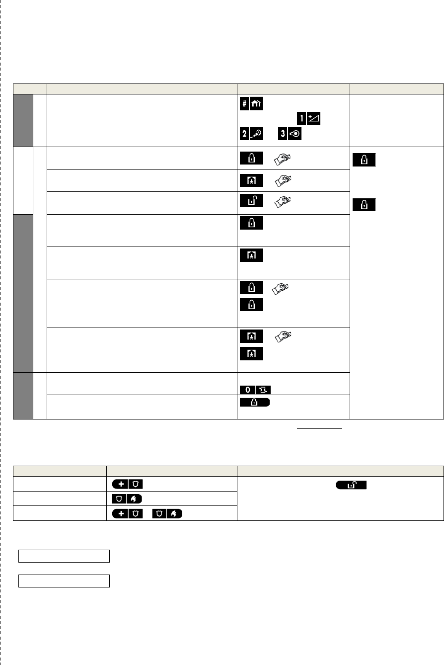
PowerMaster 360 Quick User Guide
PowerMaster 360 Quick User Guide
Arming and Disarming the System
Step
Operation
User Actions
Notes
Optional
1 Press the Partition Selection button and then
select a PARTITION (if Partition is enabled) –
used to divide the alarm system into three
independently controllable areas
followed by any
combination of ,
, or
A “protest” beep will be
heard when selecting a
partition to which no
sensors / peripherals
were enrolled.
2
Arm AWAY - used to arm the system when the
protected site is vacated entirely.
+ [ ] or enter code ARM indicator
lights steadily during
the armed state.
ARM indicator
extinguishes during the
disarmed state.
Disarming the system
also stops the siren
alarm, irrespective of
whether the alarm was
initiated during the
armed or the disarmed
state.
Arm HOME – used to arm the system when
people are present within the protected site.
+ [ ] or enter code
Disarm (OFF) – used to restore the control panel
to the normal standby state
+ [ ] or enter code
Optional
Quick arm AWAY (If Quick Arm is enabled) –
used to arm in the AWAY state without a user
code
Quick arm HOME (If Quick Arm is enabled) –
used to arm in the HOME state without a user
code
Forced arming AWAY (system not ready) – used
to arm the alarm system in the AWAY state when
any of the system zones is disturbed
+ [ ] or enter code
to silence the “protest”
buzzer
Forced arming HOME (system not ready) – used
to arm the alarm system in the HOME state
when
any of the system zones is disturbed
+ [ ] or enter code
to silence the “protest”
buzzer
Optional
3 INSTANT – used to arm in the Instant mode,
without an entry delay.
(After arming HOME/AWAY)
LATCHKEY – used for keyfob transmitters 5
through 8
Note: The factory default master user code is 1111. The code is not required if quick arming has been permitted by the
installer. Change the factory default code to a secret code without delay (see section Chapter 4, section B.4 of the
PowerMaster 360 User’s Guide).
Initiating Alarms
Alarms
Actions
Notes
Emergency alarm
(≈ 2 sec.)
To stop the alarm, press and then key in
your valid user code.
Fire alarm
(≈ 2 sec.)
Panic alarm
+ (≈ 2 sec.)
Preparing to Arm
Before arming, make sure that READY is displayed.
HH:MM READY
This indicates that all zones are secured and you may arm the system as desired.
If at least one zone is open (disturbed) the display will read:
HH:MM NOT READY
This indicates that the system is not ready for arming and in most cases that one or more
zones are not secured. However, it can also mean that an unresolved condition exists
such as certain trouble conditions, jamming etc., depending on system configuration.

PowerMaster 360 Quick User Guide
To review the open zones click . The details and location of the first open zone detector (usually an open
door or window sensor) will be displayed. To fix the open zone, locate the sensor and secure it (close the door
or window) – see "device locator" below. Each click of will display another open zone or trouble indication.
It is highly recommended to fix the open zone(s), thus restoring the system to the state of “ready to arm”. If you
do not know how to do this, consult your installer.
Note: To quit at any stage and to revert to the "READY" display, click .
Device Locator: The PowerMaster 360 system has a powerful device locator that helps you to identify open or
troubled devices indicated on the LCD display. While the LCD displays an open or faulty device, the LED on the
respective device flashes indicating "it's me". The "it's me" indication will appear on the device within max. 16
seconds and will last for as long as the LCD displays the device.
Zone Bypass Scheme
Bypassing permits arming only part of the system and at the same time allowing free movement of people within
certain zones when the system is armed. It is also used to temporarily remove from service faulty zones that
require repair work or to deactivate a sensor if, for example, you are decorating a room.
You can set the Zone Bypass Scheme i.e. to scroll through the list of registered (enrolled) sensors to your
PowerMaster 360 system and to Bypass (deactivate) faulty or disturbed sensors (either READY or NOT-
READY) or to Clear (reactivate) BYPASSED zones (sensors).
Once you have set a Bypass Scheme you can use the following 3 options:
• To quickly clear a bypassed zone i.e. to reactivate the bypassed zone – refer to Chapter 4, section B.1 of the
PowerMaster 360 User’s Guide.
• To quickly review the bypassed zones – refer to Chapter 4, section B.2 of the PowerMaster 360 User’s Guide.
• To repeat (recall) the last used zone bypassing scheme – refer to Chapter 4, section B.3 of the PowerMaster
360 User’s Guide.