Telit Wireless Solutions B2029 BT Module User Manual BlueMod B20 HWreference V101
Stollmann E+V GmbH BT Module BlueMod B20 HWreference V101
User Manual
Stollmann
E + V GmbH
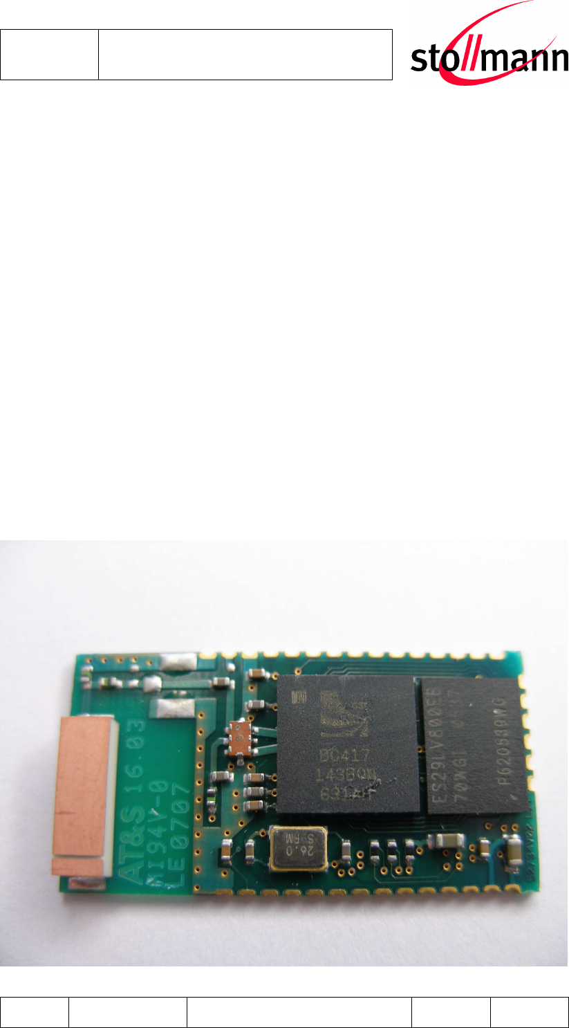
BlueMod+B20
Hardware reference
Author: bg Date of Saving: 28.03.07 Ref: BlueMod+B20_HWreference_V101.doc Revision: 1.00 Page 1 of 1
BlueMod+B20
Hardware reference

Stollmann
E + V GmbH
BlueMod+B20
Hardware reference
Author: bg Date of Saving: 28.03.07 Ref: BlueMod+B20_HWreference_V101.doc Revision: 1.00 Page 2 of 2
Note
This device was developed for the purpose of communication in an office environ-
ment. It is intended solely for our industrial clients for physical integration into their
own technical products after careful examination by experienced technical personnel
for its suitability for the intended purpose. The device was not developed for or in-
tended for use in any specific customer application. The firmware of the device may
have to be adapted to the specific intended modalities of use or even replaced by
other firmware in order to ensure flawless function in the respective areas of applica-
tion. Performance data (range, power requirements, etc.) may depend on the oper-
ating environment, the area of application, the configuration, and method of control,
as well as on other conditions of use; these may deviate from the technical specifi-
cations, the Design Guide specifications, or other product documentation. The ac-
tual performance characteristics can be determined only by measurements subse-
quent to integration. Variations in the performance data of mass-produced devices
may occur due to individual differences between such devices. Device samples
were tested in a reference environment for compliance with the legal requirements
applicable to the reference environment. No representation is made regarding the
compliance with legal, regulatory, or other requirements in other environments. No
representation can be made and no warranty can be assumed regarding the suit-
ability of the device for a specific purpose as defined by our customers. Stollmann
reserves the right to make changes to the hardware or firmware or to the specifica-
tions without prior notice or to replace the device with a successor model. Of course,
any changes to the hardware or firmware of any devices for which we have entered
into a supply agreement with our customers will be made only if, and only to the
extent that, such changes can reasonably be expected to be acceptable to our cus-
tomers. No general commitment will be made regarding periods of availability; these
must be subject to individual agreement. All agreements are subject to our Terms
and Conditions for Deliveries and Payments, a copy of which is available from
Stollmann.
Copyright © 2005-2006 Stollmann E+V GmbH
Trademarks
The Bluetooth
®
word mark and logos are owned by the Bluetooth SIG, Inc. and any
use of such marks by Stollmann E+V GmbH is under license. Other trademarks and
trade names are those of their respective owners.

Stollmann
E + V GmbH
BlueMod+B20
Hardware reference
Author: bg Date of Saving: 28.03.07 Ref: BlueMod+B20_HWreference_V101.doc Revision: 1.00 Page 3 of 3
Table of contents
1
Introduction........................................................................................................6
1.1
Feature Summary .........................................................................................6
1.2
Applications ..................................................................................................6
1.2.1
Cable Replacement Serial Point-to-point...............................................6
1.2.2
Cable Replacement Multipoint ..............................................................7
1.2.3
Terminal Server ....................................................................................7
1.2.4
PC Client...............................................................................................8
2
Block Diagram ...................................................................................................9
3
Application Interface ........................................................................................10
3.1
Power Supply..............................................................................................10
3.2
Reset ..........................................................................................................11
3.3
Serial Interface............................................................................................12
3.4
PIO Interface...............................................................................................12
3.5
I
2
C Interface................................................................................................13
3.6
Bluetooth radio Interface.............................................................................13
3.7
PCM Interface.............................................................................................14
3.8
USB Interface .............................................................................................14
3.8.1
D+, D- .................................................................................................14
3.8.2
USB Pull-Up Resistor..........................................................................14
3.8.3
USB Self-Powered Mode ....................................................................15
3.8.4
USB Bus-Powered Mode ....................................................................15
3.9
Serial Peripheral Interface...........................................................................16
3.9.1
SPI Interface Cable.............................................................................16
4
Pin Description.................................................................................................17
4.1
Pin Numbering............................................................................................17
4.2
Pin Description............................................................................................18
4.2.1
General Pin Description ......................................................................18
4.2.2
Application Specific Pin Description ....................................................19

Stollmann
E + V GmbH
BlueMod+B20
Hardware reference
Author: bg Date of Saving: 28.03.07 Ref: BlueMod+B20_HWreference_V101.doc Revision: 1.00 Page 4 of 4
4.2.2.1
SPP Pin Configuration..................................................................19
5
Electrical Characteristics..................................................................................20
5.1
Absolute Maximum Ratings ........................................................................20
5.2
Electrical Requirements ..............................................................................20
5.3
Environmental Requirements......................................................................20
5.4
Digital I/O....................................................................................................21
5.5
AIO-Interface ..............................................................................................21
5.6
USB-Interface .............................................................................................21
5.7
Power consumption and power down modes..............................................22
5.7.1
HCI Configuration ...............................................................................22
5.7.2
SPP Configuration ..............................................................................22
5.8
RF performance..........................................................................................23
5.9
Power-up time.............................................................................................24
6
Mechanical Characteristics ..............................................................................25
6.1
Dimensions.................................................................................................25
6.2
Recommended Land Pattern ......................................................................26
6.3
Reflow Temperature-Time Profile ...............................................................27
6.4
Restricted Area...........................................................................................28
6.5
Housing Guidelines.....................................................................................28
7
Safety Guidelines.............................................................................................29
8
Regulatory Information.....................................................................................29
8.1
Declaration of conformity ............................................................................29
8.1.1
FCC Compliance.................................................................................29
8.1.1.1
FCC Statement.............................................................................29
8.1.1.2
Caution.........................................................................................29
8.1.1.3
FCC Warning................................................................................29
8.1.1.4
RF-exposure Statement................................................................30
8.1.1.5
Labeling requirements for the End Product................................... 30
8.2
Bluetooth Qualification................................................................................30

Stollmann
E + V GmbH
BlueMod+B20
Hardware reference
Author: bg Date of Saving: 28.03.07 Ref: BlueMod+B20_HWreference_V101.doc Revision: 1.00 Page 5 of 5
8.3
RoHS Declaration.......................................................................................32
9
Related Documents .........................................................................................32
10
Ordering Information.....................................................................................32
11
Life Support Policy........................................................................................32
12
History ..........................................................................................................33

Stollmann
E + V GmbH
BlueMod+B20
Hardware reference
Author: bg Date of Saving: 28.03.07 Ref: BlueMod+B20_HWreference_V101.doc Revision: 1.00 Page 6 of 6
1 Introduction
This Hardware Reference Guide documents how the BlueMod+B20 can be inte-
grated into customer systems. It addresses developers of hardware environments
for the BlueMod+B20. For detailed information about software interfaces refer to the
software reference manual.
1.1 Feature Summary
• Bluetooth specification V2.0+EDR (Enhanced Data Rate)
• CSR BlueCore4-External inside
• Complete Co-location and Co-existence with 802.11 (AWMA, AFH and
SFH)
• Fast Connection Setup
• RF output power class 2 with power control
• Supply Voltage 3.3V
• Internal crystal oscillator (16 MHz)
• Surface mount type: BlueMod+B20: 14.5 x 28.0 x 2.0 mm³
• Bluetooth enhanced data rate up to 2178kbps asymmetric
• Support for all Bluetooth power saving modes (Park, Sniff, Hold)
• µ-law, A-law and CVSD transcoders on SCO channel
• 13 or 16 bit linear, 8 bit µ-law or a-law PCM interface
• Full 8- to 128-bit encryption
• High sensitivity design (-81 dBm typ.)
• USB, UART and I
2
C interface
• 11 digital + 2 analog IO’s for individual usage by embedded software
• 16bit RISC core for embedded profiles or application software
• Power control
• Manufactured in conformance with RoHS
1.2 Applications
BlueMod+B20 can be used in different applications. Some typical are described in
this chapter. For application requiring an external adapter please refer to other
BlueRS+ versions from Stollmann.
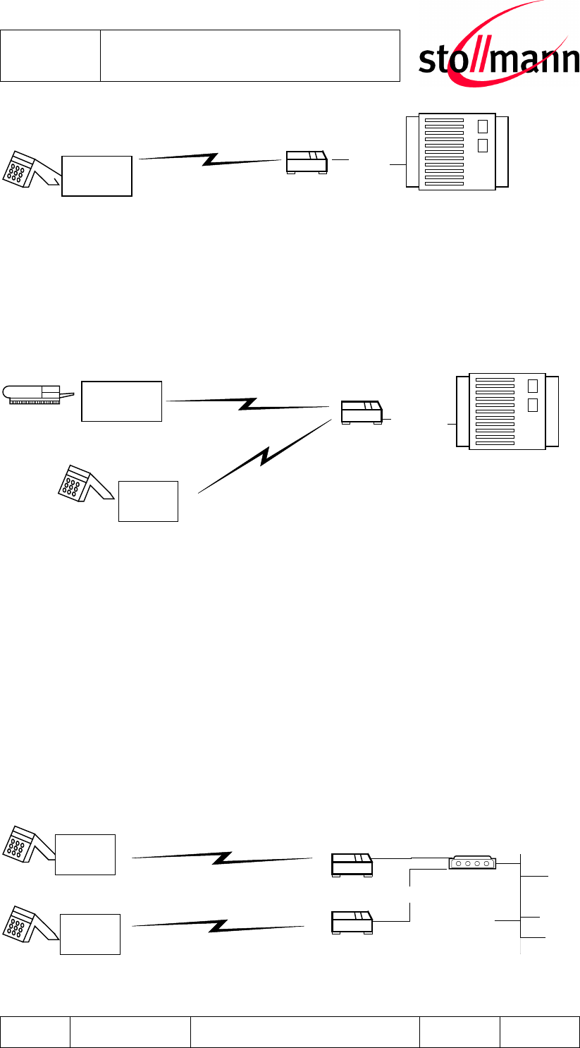
1.2.1 Cable Replacement Serial Point-to-point
To establish a cable replacement between two devices with a serial interface,
BlueMod+B20 can be used.
Stollmann
E + V GmbH
BlueMod+B20
Hardware reference
Author: bg Date of Saving: 28.03.07 Ref: BlueMod+B20_HWreference_V101.doc Revision: 1.00 Page 7 of 7
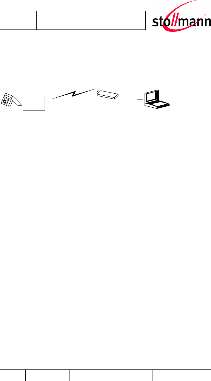
1.2.2 Cable Replacement Multipoint
Since several devices may be connected with a master device via Bluetooth, several
end devices can also be multiplexed via Bluetooth. This adaptation is shown below
for a desktop device.
Bluetooth
Multiplxing
protocol
RS-232
BlueRS+
Control Unit
Device
Bluetooth
BlueMod
+B20
BlueMod+
B20
In order to handle multiple links a multiplexing protocol is required for the communi-
cation between devices, the BlueRS+ and the host. The BlueRS+ has to be adapted
to the routing scheme of the protocol to transmit the data in an appropriate way. This
includes Bluetooth connection control (i.e. are the Bluetooth links permanently active
or only on demand) and data distribution (i.e. are all data from the host to be for-
warded to all devices or only depending on the address header; are data from the
devices are transmitted to the host transparently or is an address header to be
added). In case you have a multipoint application please contact Stollmann for spe-
cific support.
1.2.3 Terminal Server
Bluetooth
RS-232
BlueRS+ Control Unit
BlueMod
+B20
Bluetooth
Terminal
Server
BlueRS+
Bluetooth
RS-232
BlueMod+
B20
BlueMod+
B20
Stollmann
E + V GmbH
BlueMod+B20
Hardware reference
Author: bg Date of Saving: 28.03.07 Ref: BlueMod+B20_HWreference_V101.doc Revision: 1.00 Page 8 of 8
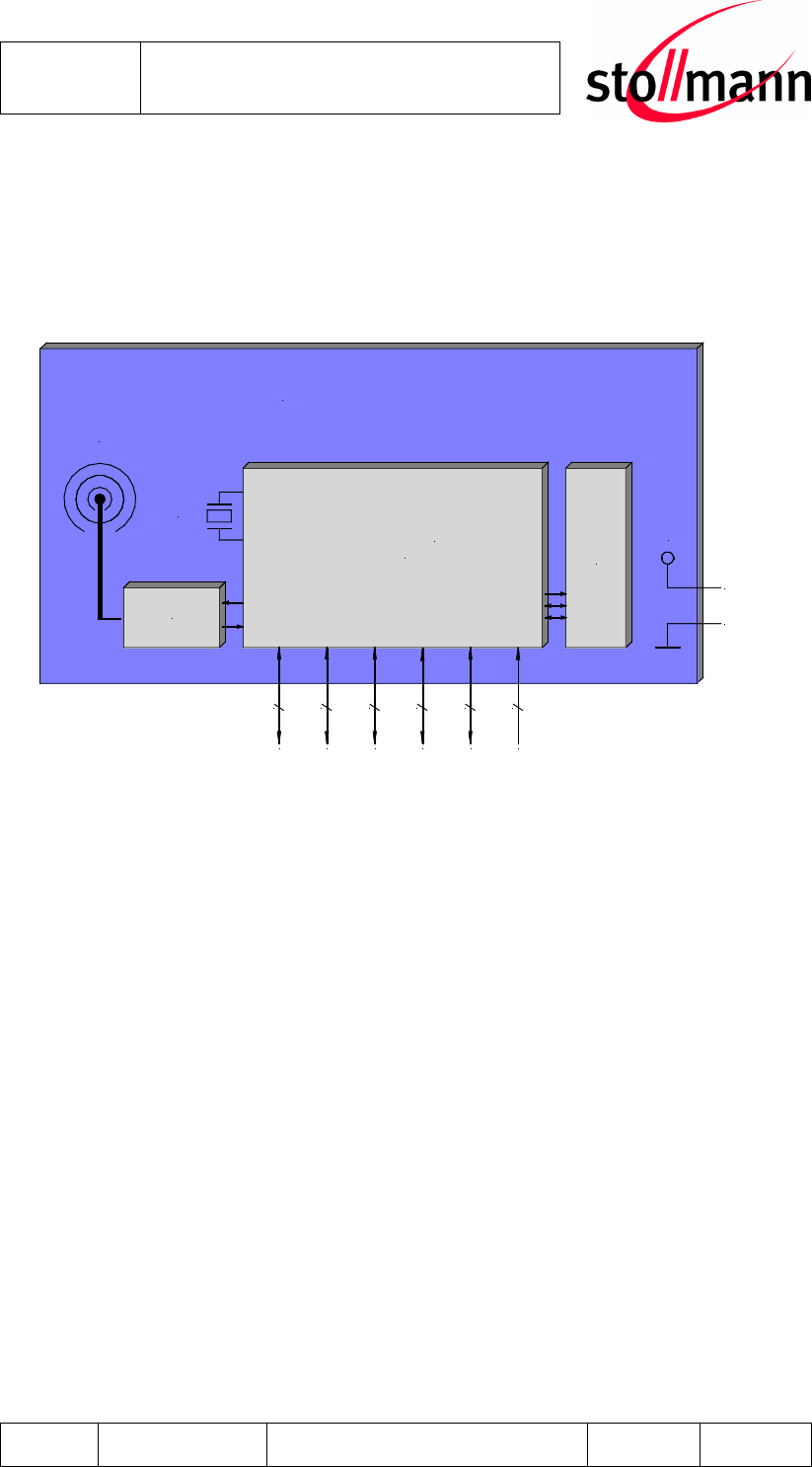
1.2.4 PC Client
BlueMod+B20 as Bluetooth Client can establish connections with other Bluetooth
interfaces, e.g. in PCs.
Bluetooth
PC
PCMCI
A
USB
BluePCMCIA+
BlueUSB+
BlueMod+
B20
Stollmann
E + V GmbH
BlueMod+B20
Hardware reference
Author: bg Date of Saving: 28.03.07 Ref: BlueMod+B20_HWreference_V101.doc Revision: 1.00 Page 9 of 9
2 Block Diagram
Flash
8Mb
BlueCore 4
External VCC
BlueMod+B20
TM
Combo
Filter
RESET
SPI
UART
PCM
PIO
USB
1
4
4
4
12+2
2
GND
3.3V
26MHz
onboard
antenna
Figure: BlueMod+B20 block diagram

Stollmann
E + V GmbH
BlueMod+B20
Hardware reference
Author: bg Date of Saving: 28.03.07 Ref: BlueMod+B20_HWreference_V101.doc Revision: 1.00 Page 10 of 10
3 Application Interface
3.1 Power Supply
The BlueMod+B20 requires a power supply with the following characteristics:
3.3V ± 0.1V low noise (≤10mV) >80mA peak
Due to the technological requirements and the pulsed radio transmission the supply
needs to be fed by an ultra fast (response time ≤20µs) linear regulator placed as
close as possible to the VSUP pin (22). Functionality has been verified with the fol-
lowing types: TOREX: XC6204x332xx or XC6401xx42xx
It is also recommended to place a low ESR capacitor with at least 10µF as close as
possible to the VSUP pin (22).
NOTE: You must ensure that during operation the supply voltage never drops below
3.0 V. Otherwise the flash contents (firmware and/or configuration data) can get lost.
Stollmann
E + V GmbH
BlueMod+B20
Hardware reference
Author: bg Date of Saving: 28.03.07 Ref: BlueMod+B20_HWreference_V101.doc Revision: 1.00 Page 11 of 11
3.2 Reset
The BlueMod+B20 is equipped with circuitry for generating Power Down Reset from
the internal core voltage. A reset is generated when the core voltage falls below
typically 1.5V and is released when it rises above typically 1.6V.
Via Pin 31 an external reset is generated by holding RESET# at ≤ 0.3V for ≥ 5ms.
It is strongly recommended to use external Power ON Reset circuitry, which holds
RESET# at ≤ 0.3V for ≥ 5ms after VSUP has stabilized in the recommended volt-
age range.
The following table shows the pin states of BlueMod+B20 on reset.
Pin Name State: BlueMod+B20
PIO[11:0] Input with weak pull down
PCM_OUT Output tri-stated with weak pull down
PCM_IN Input with weak pull down
PCM_SYNC Input with weak pull down
PCM_CLK Input with weak pull down
UART_TX Output tri-stated with weak pull up
UART_RX Input with weak pull down
UART_RTS# Output tri-stated with weak pull up
UART_CTS# Input with weak pull down
USB_DP Input with weak pull down
USB_DN Input with weak pull down
SPI_CS# Input with weak pull up
SPI_CLK Input with weak pull down
SPI_MOSI Input with weak pull down
SPI_MISO Output tri-stated with weak pull down
AIO[2:0] Output, driving low
RESET# Input with weak pull up
Stollmann
E + V GmbH
BlueMod+B20
Hardware reference
Author: bg Date of Saving: 28.03.07 Ref: BlueMod+B20_HWreference_V101.doc Revision: 1.00 Page 12 of 12
3.3 Serial Interface
The interface functionally corresponds to V.24 / RS-232 but has TTL-level.
• Transmission speeds 1200 – 2764800 bps (asynchronous)
• Character representation: 8 Bit, even/odd/no Parity, 1 or 2 stop bits
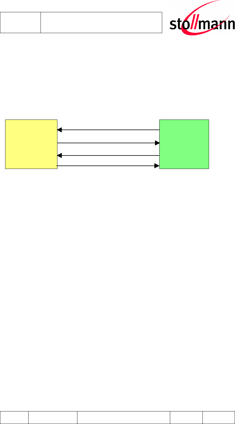
• hardware flow-control with UART_RTS and UART_CTS (active low)
BlueMod+B20
Host
RXD
TXD
CTS
RTS
3.4 PIO Interface
It is possible to use the programmable digital I/Os PIO[0:11] and the programmable
analog I/Os AIO[0:1] on the BlueMod+B20. Their behavior has to be defined project
specific in the firmware.
Stollmann
E + V GmbH
BlueMod+B20
Hardware reference
Author: bg Date of Saving: 28.03.07 Ref: BlueMod+B20_HWreference_V101.doc Revision: 1.00 Page 13 of 13
3.5 I
2
C Interface
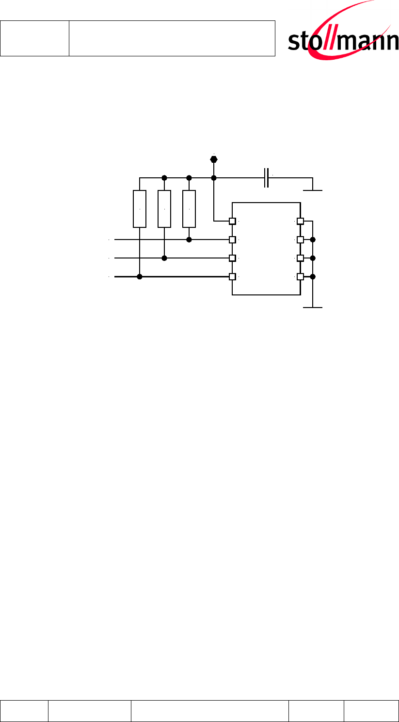
PIO[8:6] can be used to form a master I
2
C interface. The interface is formed using
software to drive these lines. Therefore, it is suited only to relatively slow functions
i.e. EEPROM.
2.2k
2.2k
2.2k
VCC
WP
SCL
SDA
A0
A1
A2
GND
10nF
+1.8V
PIO[8]
PIO[6]
PIO[7]
Example EEPROM connection
BluMod+B20 interfaces directly to EEPROM devices including the following:
• Atmel AT24Cxxx
• Catalyst CAT24WCxxx
• Fairchild FM24Cxxx
• Microchip 24AAxxx
• Philips PCF8582C-2, PCF8594C-2, PCF8598C-2
• Seiko 24Cxx, 24CSxx
• Rohm BR24Cxx
• ST M24C32, M24C64, M24128-B, M24256-B,M24512
3.6 Bluetooth radio Interface
The BlueMod+B20 presents an integrated ceramic antenna.
It is highly recommended that you follow the design rule given in the Stollmann Ap-
plication Note on Antenna design [2].

Stollmann
E + V GmbH
BlueMod+B20
Hardware reference
Author: bg Date of Saving: 28.03.07 Ref: BlueMod+B20_HWreference_V101.doc Revision: 1.00 Page 14 of 14
3.7 PCM Interface
PCM or Pulse Code Modulation is a sampling technique for digitising analogue sig-
nals.
The PCM interface for voice applications is provided via the PCM_OUT, PCM_IN,
PCM_CLK and PCM_SYNC pins.
The PCM interface can act as master or as slave device.
In master mode, clock frequencies of 128kHz, 256kHz or 512kHz can be generated,
when using the internal 4MHz clock. In slave mode, clock frequencies up to
2048kHz are accepted.
The Frame Clock is 8kHz. Long and Short Frame Sync are supported.
BlueMod+B20 interfaces directly to PCM audio devices including the following:
• Qualcom MSM3000 series and MSM5000 series CDMA base band devices
• OKI MSM7705 four channel A-law and µ-law codec
• Motorola MC145481 8-bit A-law and µ-law codec
• Motorola MC145483 13-bit linear codec
• STW 5093 5094 14-bit linear codec
3.8 USB Interface
3.8.1 D+, D-
The BlueMod+B20 contains a full speed USB version 1.1 compliant interface capa-
ble of directly driving a USB cable. The BlueMod+B20 operates as a USB peripheral
and responds to requests from a USB master host controller.
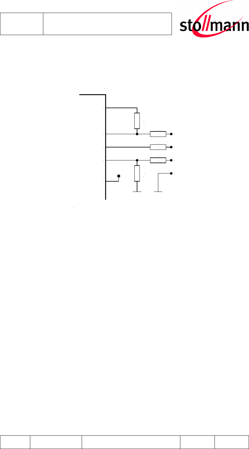
3.8.2 USB Pull-Up Resistor
In self powered mode a 1.5KΩ pull up resistor needs to be connected between PIO2
and the USB D+ line. This pulls the USB D+ line high when the BlueMod+B20 is
ready for enumeration, signalling to the host controller that the BlueMod+B20 is a
full speed (12Mbps) USB device.
In bus powered mode an internal pull up resistor can be used. For details see SW
description.
Stollmann
E + V GmbH
BlueMod+B20
Hardware reference
Author: bg Date of Saving: 28.03.07 Ref: BlueMod+B20_HWreference_V101.doc Revision: 1.00 Page 15 of 15
3.8.3 USB Self-Powered Mode
In USB self-powered mode, the BlueMod+B20 is powered from its own power sup-
ply and not from the USB Vbus line. In order to detect when the USB Vbus line is
powered up, the USB Vbus line is monitored by PIO4 through a voltage divider .
Rvb1
22k
Rs
27R
Rs
27R
Rpu
1k5
Rvb2
47k
D+
D-
VBUS
GND
PIO2/USB-Pull_Up
USB_DP
USB_DN
PIO4/USB_ON
BlueMod+B20
Connections in self powered mode
VSUP
+3.3V
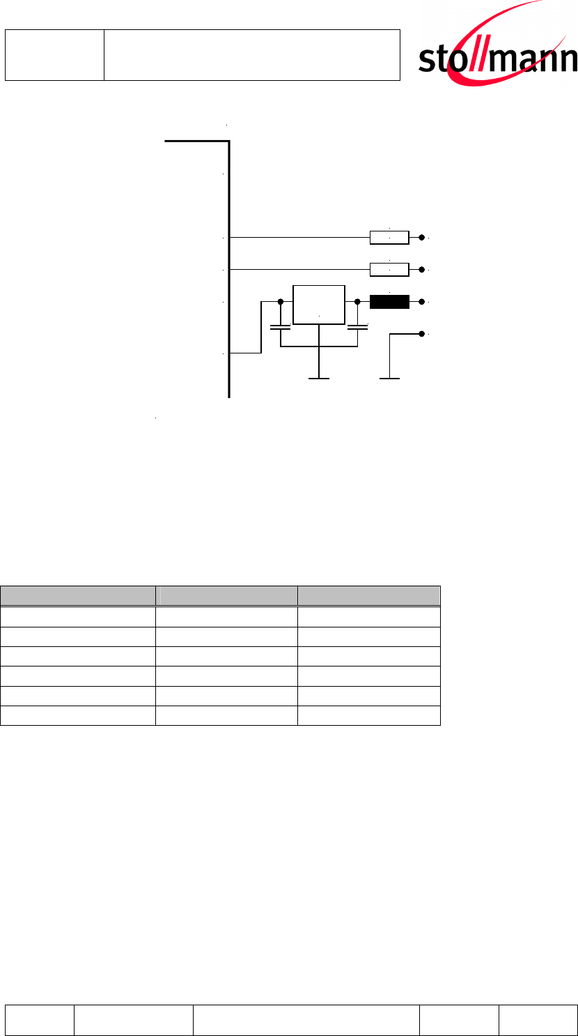
3.8.4 USB Bus-Powered Mode
In USB bus-powered mode, the BlueMod+B20 is powered from the USB Vbus line
by means of a Low Drop Out (LDO) Voltage Regulator. When choosing the LDO
Voltage Regulator for supplying the +3.3V power to the BlueMod+B20, some factors
that need to be considered are:
• The voltage specification for the USB Vbus line is +4.75V to +5.25V.
• The total current required (average and peak) for the design.
• The voltage regulator’s drop out voltage vs. output current.
• The voltage regulator’s power dissipation over the operating temperature range.
• Filtering requirements on the USB Vbus line to attenuate noise above the volt-
age regulator’s bandwidth.
• The suspend state current draw.
Stollmann
E + V GmbH
BlueMod+B20
Hardware reference
Author: bg Date of Saving: 28.03.07 Ref: BlueMod+B20_HWreference_V101.doc Revision: 1.00 Page 16 of 16
PIO2/USB-Pull_Up
L
Rs
27R
Rs
27R
D+
D-
VBUS
GND
USB_DP
USB_DN
PIO4/USB_ON
BlueMod+B20
VSUP
Regulator
+3.3V
C C
Connections in bus powered mode
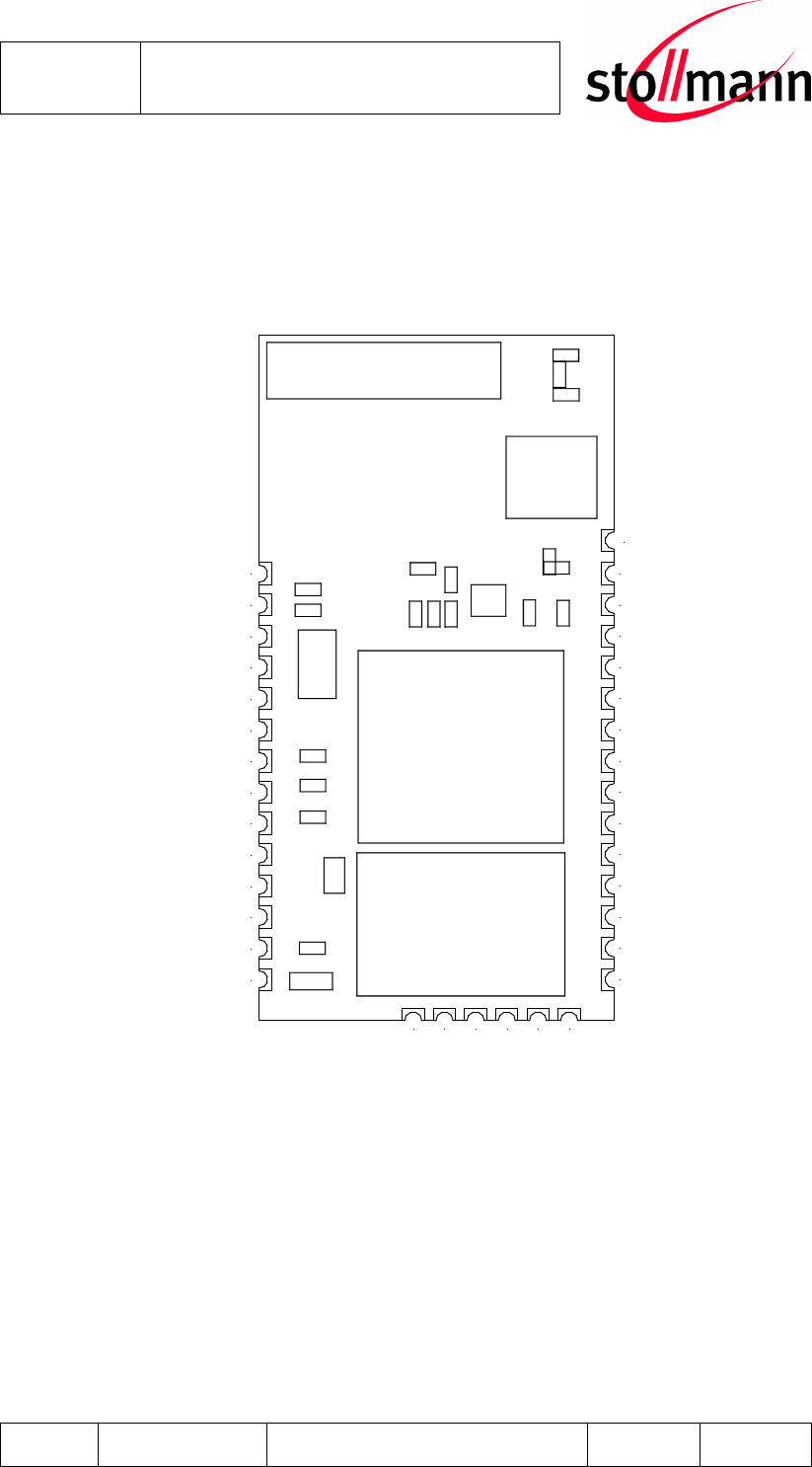
3.9 Serial Peripheral Interface
BlueMod+B20 uses a 16-bit-data and16-bit-address Serial Peripheral Interface
(SPI). This interface is used for configuration, firmware flash and debug purposes
only.
3.9.1 SPI Interface Cable
SPI Signal Name B20 Pin LPT Sub-D 25 Pin
MISO 30 10
MOSI 27 8
CLK 28 9
CS# 29 2
XAP_RESET 31 16
GND 2,21,34,35 18 to 25
Stollmann
E + V GmbH
BlueMod+B20
Hardware reference
Author: bg Date of Saving: 28.03.07 Ref: BlueMod+B20_HWreference_V101.doc Revision: 1.00 Page 17 of 17
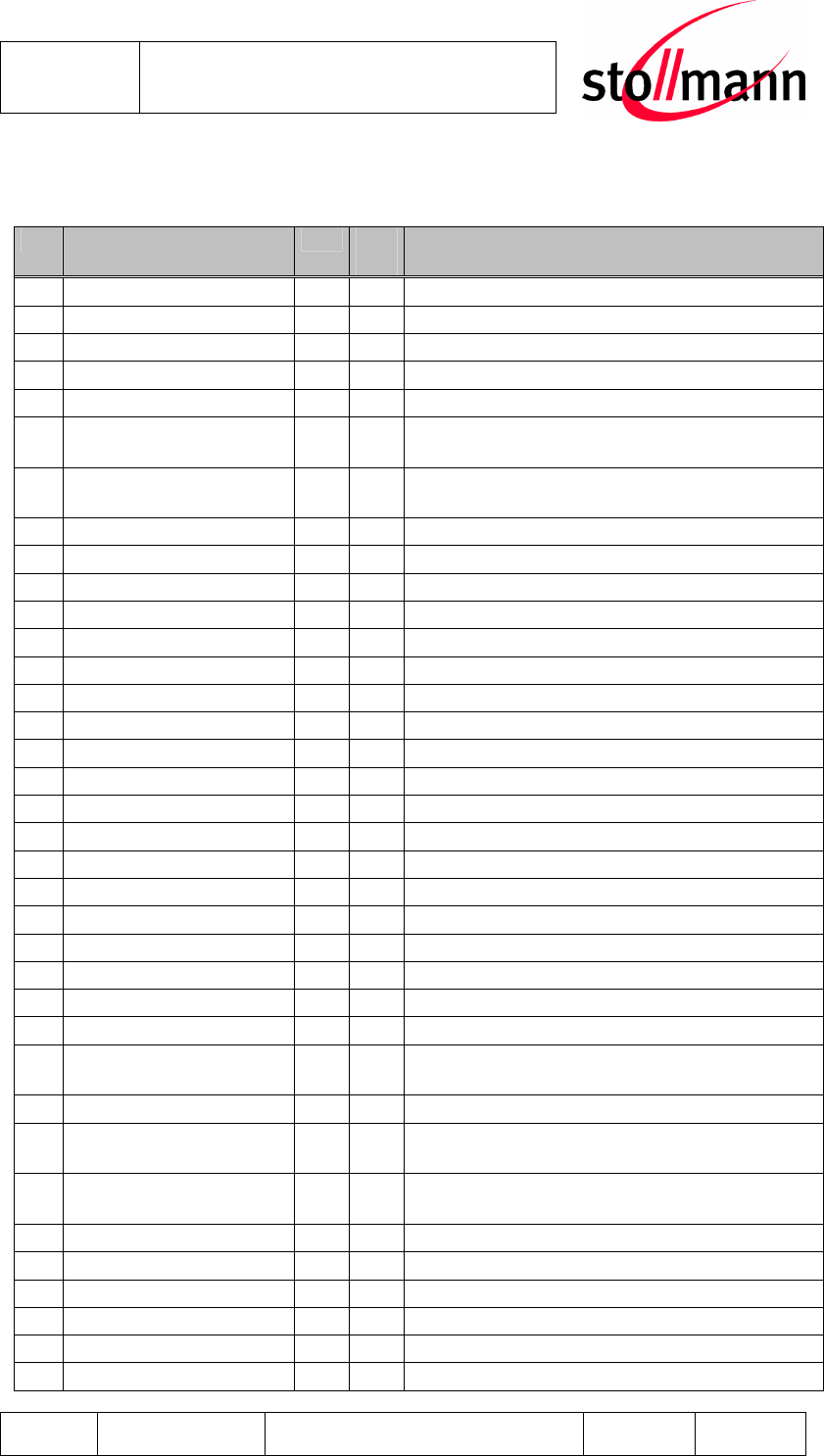
4 Pin Description
4.1 Pin Numbering
1 ANT
2 GND
3 PIO0
4 PIO1
5 PIO2
6 PIO3
7 PIO4
8 PIO5
9 PIO6
10 PIO7
11 PIO8
12 PIO9
13 PIO10
14 PIO11
GND 34
AIO0 33
AIO1 32
RESET 31
SPI_MISO 30
SPI_CSB 29
SPI_CLK 28
SPI_MOSI 27
UART_CTS 26
UART_TX 25
UART_RTS 24
UART_RX 23
VSUP 22
GND 21
USB_DN 15
USB_DP 16
PCM_CLK 17
PCM_OUT 18
PCM_IN 19
PCM_SYNC 20
35 GND
Figure 4.1 BlueMod+B20 Pin Numbering
Stollmann
E + V GmbH
BlueMod+B20
Hardware reference
Author: bg Date of Saving: 28.03.07 Ref: BlueMod+B20_HWreference_V101.doc Revision: 1.00 Page 18 of 18
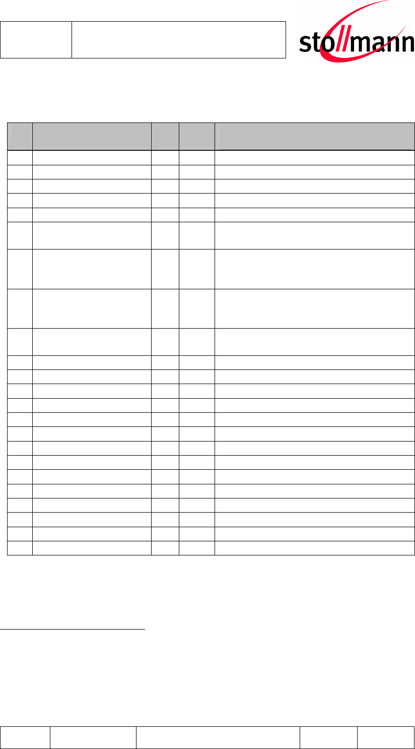
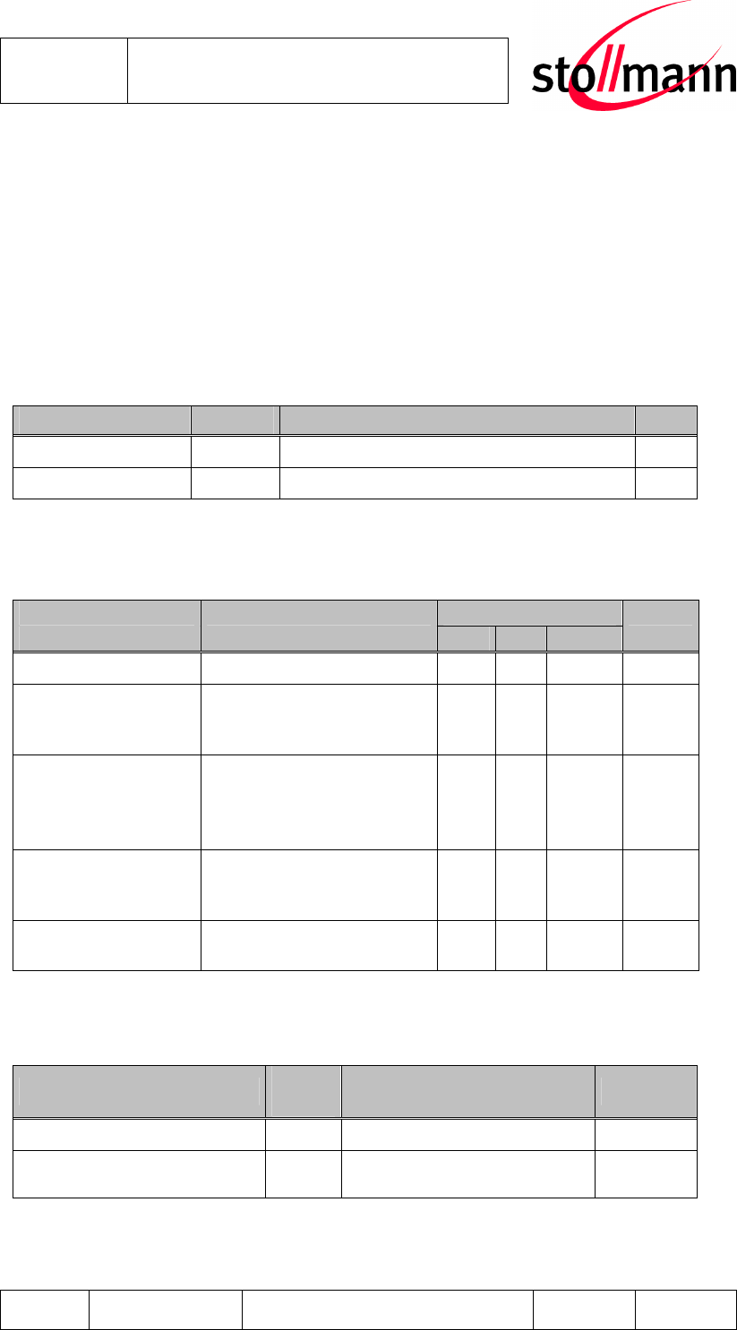
4.2 Pin Description
4.2.1 General Pin Description
No Pin Name
Dir ac-
tive
BlueMod+B20 usage
1 NC Not Connected
2 GND - - Ground
3 PIO0/RXEN I/O H PIO/Control output for external LNA
4 PIO1/TXEN I/O H PIO/Control output for ext. PA (class1)
5 PIO2/USB_Pull_Up I/O H PIO/USB pull up in self powered mode
6 PIO3/USB_Wake_Up I/O H PIO/USB output, to wake up PC when in
USB mode
7 PIO4/USB_ON I/O H PIO/USB input, VBUS detect in self pow-
ered mode
8 PIO5/USB_Detach I/O H PIO/USB input, detaches from USB
9 PIO6/SCL I/O - PIO/ I
2
C Serial Clock
10 PIO7/SDA I/O - PIO/ I
2
C Serial data
11 PIO8/WP I/O - PIO/ I
2
C Write Protect
12 PIO9 I/O - PIO
13 PIO10 I/O - PIO
14 PIO11 I/O - PIO
15 USB_DN I/O - USB Data-
16 USB_DP I/O - USB Data+
17 PCM_CLK I/O - PCM Bit clock
18 PCM_OUT O - PCM Data Output
19 PCM_IN I - PCM Data Input
20 PCM_SYNC I/O - PCM Frame Sync
21 GND - - Ground
22 VSUP - - 3.3V Supply Voltage
23 UART_RX I - UART Asynchronous Receive Data
24 UART_RTS# O L UART Request To Send
25 UART_TX O - UART Asynchronous Transmit Data
26 UART_CTS# I L UART Clear To Send
27 SPI_MOSI I - Synchronous Peripheral Interface
Data Master Out – Slave In
28 SPI_CLK I - Synchronous Peripheral Interface Clock
29 SPI_CS# I L Synchronous Peripheral Interface Chip
Select
30 SPI_MISO O - Synchronous Peripheral Interface
Data Master In- Slave Out
31 RESET# I L Module Reset
32 AIO0 I/O - Analogue Input/Output
33 AIO1 I/O - Analogue Input/Output
34 GND - - Ground
35 GND - - Ground
Stollmann
E + V GmbH
BlueMod+B20
Hardware reference
Author: bg Date of Saving: 28.03.07 Ref: BlueMod+B20_HWreference_V101.doc Revision: 1.00 Page 19 of 19
4.2.2 Application Specific Pin Description
4.2.2.1 SPP Pin Configuration
No Pin Name
Dir ac-
tive
BlueMod+B20 SPP configuration
usage
1 NC Not Connected
2 GND - - Ground
3 PIO0 or RXEN I/O H PIO/Control output for external LNA
4 PIO1 or TXEN I/O H PIO/Control output for ext. PA (class1)
5 LED1# O L Status LED 1
6 DCD# I/O L Data Carrier Detect Input in DTE
mode; Output in DCE mode
7 RTC-IN# I L DSR – Data Set Ready in DTE mode;
DTR – Data Terminal Ready in DCE
mode
8 RTC-OUT# O L DSR – Data Set Ready in DCE mode;
DTR – Data Terminal Ready in DTE
mode
9 RI# or SCL
1
I/O - RING Input in DTE mode; Output in
DCE mode or I
2
C Serial Clock
10 SDA
1
I/O - I
2
C Serial Data
11 WP
1
O - I
2
C Write Protect
12 LED2# O L Status LED 2
13 reserved
14 reserved
21 GND - - Ground
22 VSUP - - 3.3V Supply Voltage
23 UART_RX I - UART Asynchronous Receive Data
24 UART_RTS# O L UART Request To Send
25 UART_TX O - UART Asynchronous Transmit Data
26 UART_CTS# I L UART Clear To Send
31 RESET# I L Module Reset
34 GND - - Ground
35 GND - - Ground
For USB, PCM, SPI and Analog IO pins see 4.2.1 General Pin Description, these
pins are not used in SPP configuration.
1
subject to firmware support, contact Stollmann for current status.
Stollmann
E + V GmbH
BlueMod+B20
Hardware reference
Author: bg Date of Saving: 28.03.07 Ref: BlueMod+B20_HWreference_V101.doc Revision: 1.00 Page 20 of 20
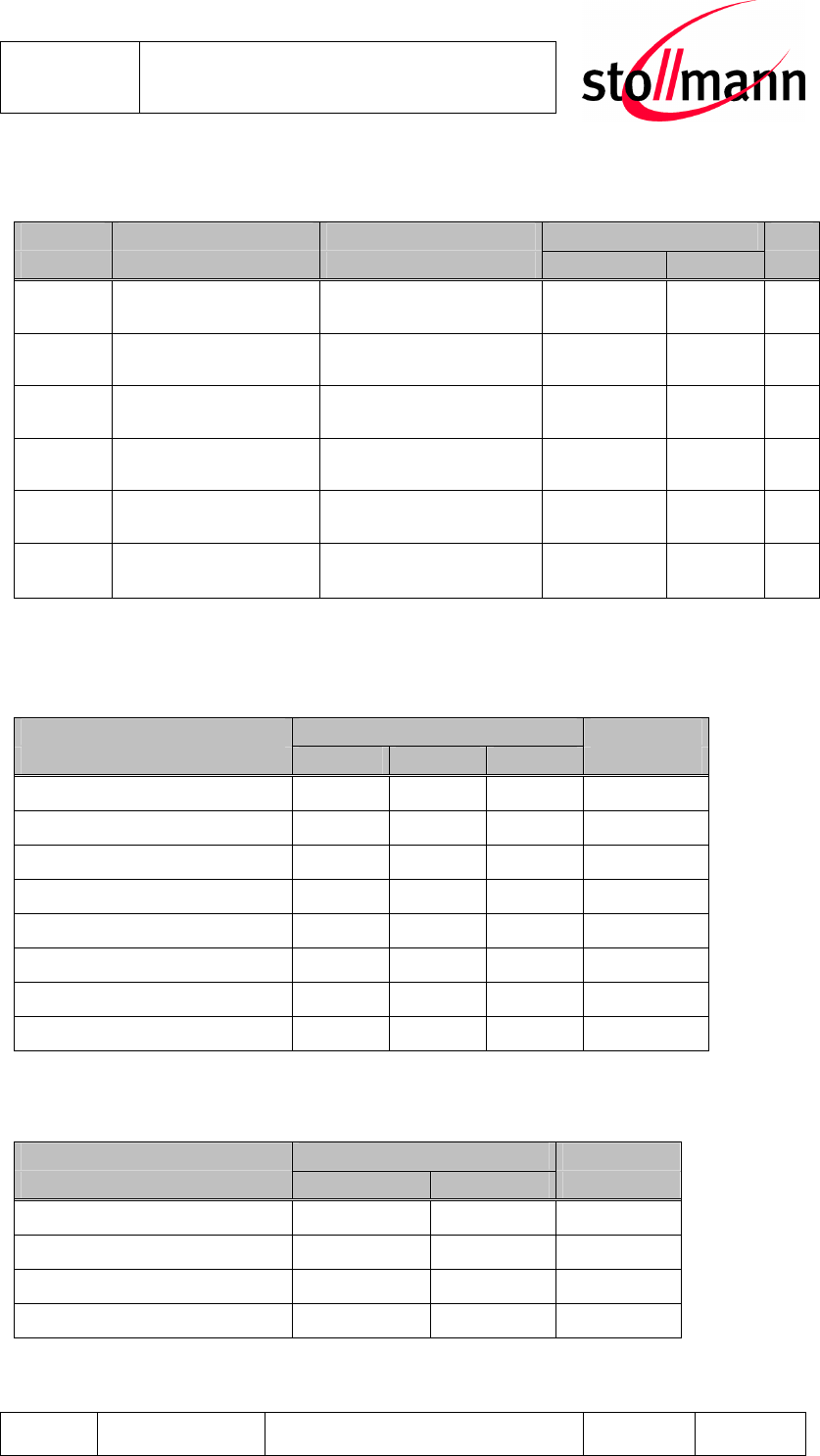
5 Electrical Characteristics
5.1 Absolute Maximum Ratings
Stresses beyond those listed under “Absolute Maximum Ratings” may cause per-
manent damage to the device. These are stress ratings only, and functional opera-
tion of the device at these or any other conditions beyond those indicated under
“Electrical Requirements” is not implied. Exposure to absolute-maximum-rated con-
ditions for extended periods may affect device reliability.
Item Symbol Absolute Maximum Ratings Unit
Supply voltage V
SUP
-0.4 to +3.7 V
Voltage on any pin
V
Pin
GND -0.3 to VSUP +0.4 V
5.2 Electrical Requirements
VSUP = 3.3V, T
amb
= 25°C if nothing else stated
Item Condition Limit Unit
Min Typ Max
Frequency Range 2400
2483.5
MHz
Load impedance Measured with network
analyzer in the frequency
range at antenna pin 50 Ohm
Output return loss
Receive Mode to 50Ω
load
Transmit Mode to 50Ω
load
-10
-10 dBm
Supply voltage
VSUP
The typical voltage is
recommended VSUP at
voltage pin 2.8 3.3 3.6 Vdc
Ripple on Vcc Ripple frequency
≤10MHz 10 mVrms
5.3 Environmental Requirements
Item Sym-
bol Absolute Maximum Ratings
Unit
Storage temperature range
T
stg
-40 to +105 °C
Operating temperature
range T
op
-40 to +85 °C
Stollmann
E + V GmbH
BlueMod+B20
Hardware reference
Author: bg Date of Saving: 28.03.07 Ref: BlueMod+B20_HWreference_V101.doc Revision: 1.00 Page 21 of 21
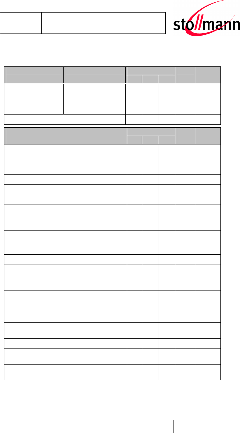
5.4 Digital I/O
VSUP = 3.3V, T
amb
= 25°C
Symbol Item Condition Limit Unit
Min Max
V
IL
Low-Level Input
Voltage - 0.8 V
V
IH
High-Level Input
Voltage 0.7xVSUP - V
V
OL
Low-Level Output
Voltage I
OL
= 4mA - 0.2 V
V
OH
High-Level Output
Voltage I
OH
= -4mA VSUP-0.2 - V
I
OL
Low -Level Output
Current V
OL
= 0.55V - 4 mA
I
OH
High-Level Output
Current V
OH
= 2.3V /100k PU
V
OH
= 2.3V /10k PU - -4 mA
5.5 AIO-Interface
VSUP = 3.3V, T
amb
= 25°C
Item Limit Unit
Min Typ Max
Resolution - - 8 Bits
Input voltage range 0 1.7 V
Accuracy -1 1 LSB
Offset -1 1 LSB
Gain error -0.8 0.8 %
Input bandwidth 100 kHz
Conversion time - 2.5 - µs
Sample rate 700 Samples/s
5.6 USB-Interface
VSUP = 3.3V, T
amb
= 25°C
Item Unit
Min Max
Input logic level low - 0.3xVSUP V
Input logic level high 0.7xVSUP - V
Output logic level low )* 0 0.2 V
Output logic level high )* 2.8 VSUP V
)* connected to correctly terminated USB cable

Stollmann
E + V GmbH
BlueMod+B20
Hardware reference
Author: bg Date of Saving: 28.03.07 Ref: BlueMod+B20_HWreference_V101.doc Revision: 1.00 Page 22 of 22
5.7 Power consumption and power down modes
5.7.1 HCI Configuration
tbd
5.7.2 SPP Configuration
The following values are approximate power consumption values in the different
states:
VSUP = 3.3V, T
amb
= 25°C
Device Role Condition
Master Slave
Unit
Idle, all functions available, no
Bluetooth link 7- 25 mA
Bluetooth connected, no data
traffic 5 21 mA
Bluetooth connected, data
traffic 115 kbit/s 22 29 mA
Device in reset 0,06 mA
Stollmann
E + V GmbH
BlueMod+B20
Hardware reference
Author: bg Date of Saving: 28.03.07 Ref: BlueMod+B20_HWreference_V101.doc Revision: 1.00 Page 23 of 23
5.8 RF performance
Vcc = 3.3V , T
amb
= +20°C, 50 Ω antenna
Receiver Frequency [GHz] Limit BT Unit
Min Typ Max
Spec
2.402 -83 -81 -78
2.441 -83 -81 -78
Sensitivity at 0.1%
BER 2.480 -83 -81 -78
≤-70 dBm
Maximum received signal at 0.1% BER -20 - - ≥-20 dBm
Transmitter Limit BT Unit
Min
Typ Max
Spec
RF transmit power 50 Ω load, at antenna 1 5 - -6 to
+4 dBm
RF power control range 25 35 - ≥16 dB
RF power range control resolution - 0.5 1.2 - dB
20 dB bandwidth for modulated carrier - .79 1.0 ≤1.0 MHz
Initial carrier frequency tolerance -75
0 +75
≤ ±75
kHz
Carrier frequency drift (packet DH1) - 8 25 ≤ ±25
kHz
Drift Rate - 7 20 ≤20 kHz/50
µs
∆f1
avg
“Maximum Modulation” 140
163 175 ≥140
to
≤175 kHz
∆f2
avg
“Minimum Modulation” 115
154 - ≥ 115
kHz
C/I co-channel tbd -
0
≤ 11 dB
Adjacent channel selectivity C/I f = f
0
±
1MHz tbd -
0
≤ 0 dB
Adjacent channel selectivity C/I f = f
0
±
2MHz tbd -
0
≤ -30 dB
Adjacent channel selectivity C/I f ≥ f
0
+3MHz tbd -
0
≤ -40 dB
Adjacent channel selectivity C/I f ≤ f
0
-
3MHz tbd -
0
≤ -40 dB
Adjacent channel selectivity C/I f = f
image
tbd -
0
≤ -9 dB
Adjacent channel Transmit power f = f
0
±
2MHz - -35 -20 ≤ -20 dBc
Adjacent channel Transmit power f = f
0
±
3MHz - -45 -40 ≤ -40 dBc
Note: The tests were made to the Bluetooth regulation, with the BER limit of 0,1%.
With the output limits given as a minimum value, there was no bit error failure and
the test was pass. Therefore the maximum values were not measured.

Stollmann
E + V GmbH
BlueMod+B20
Hardware reference
Author: bg Date of Saving: 28.03.07 Ref: BlueMod+B20_HWreference_V101.doc Revision: 1.00 Page 24 of 24
5.9 Power-up time
The time until the BlueMod+B20 is able to accept link requests or serial data is
about tbd seconds after power-up.
Stollmann
E + V GmbH
BlueMod+B20
Hardware reference
Author: bg Date of Saving: 28.03.07 Ref: BlueMod+B20_HWreference_V101.doc Revision: 1.00 Page 25 of 25
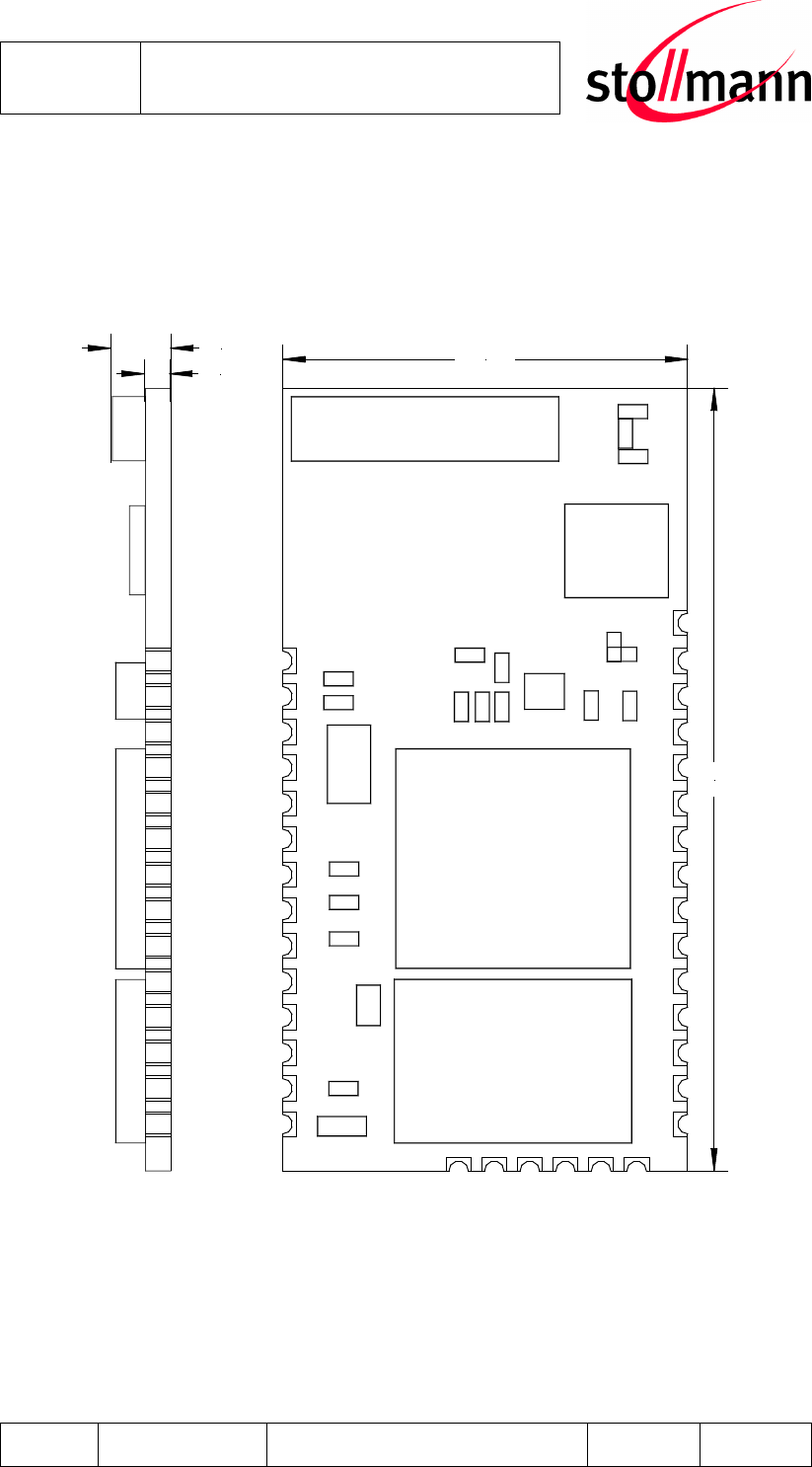
6 Mechanical Characteristics
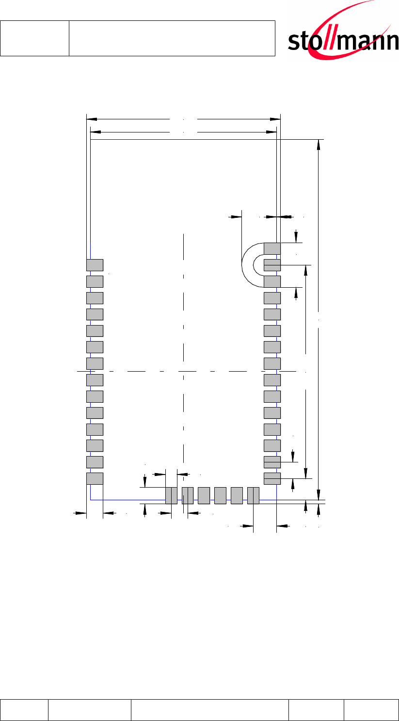
6.1 Dimensions
14,5
0,9
2,2
28
Figure 6.1 BlueMod+B20 dimensions
Stollmann
E + V GmbH
BlueMod+B20
Hardware reference
Author: bg Date of Saving: 28.03.07 Ref: BlueMod+B20_HWreference_V101.doc Revision: 1.00 Page 26 of 26
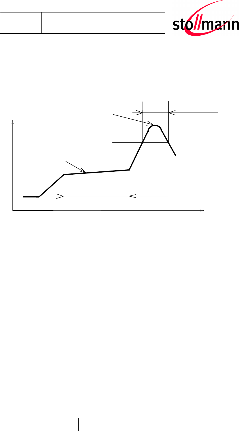
6.2 Recommended Land Pattern
BlueMod+B20
top view
14,5
16,58
1,275
1,275
28
15,1
1,3
1,3
0,9
1,675
0,3
0,3
1,825
2,7
3,5
Figure 6.2 BlueMod+B20 land pattern
Stollmann
E + V GmbH
BlueMod+B20
Hardware reference
Author: bg Date of Saving: 28.03.07 Ref: BlueMod+B20_HWreference_V101.doc Revision: 1.00 Page 27 of 27
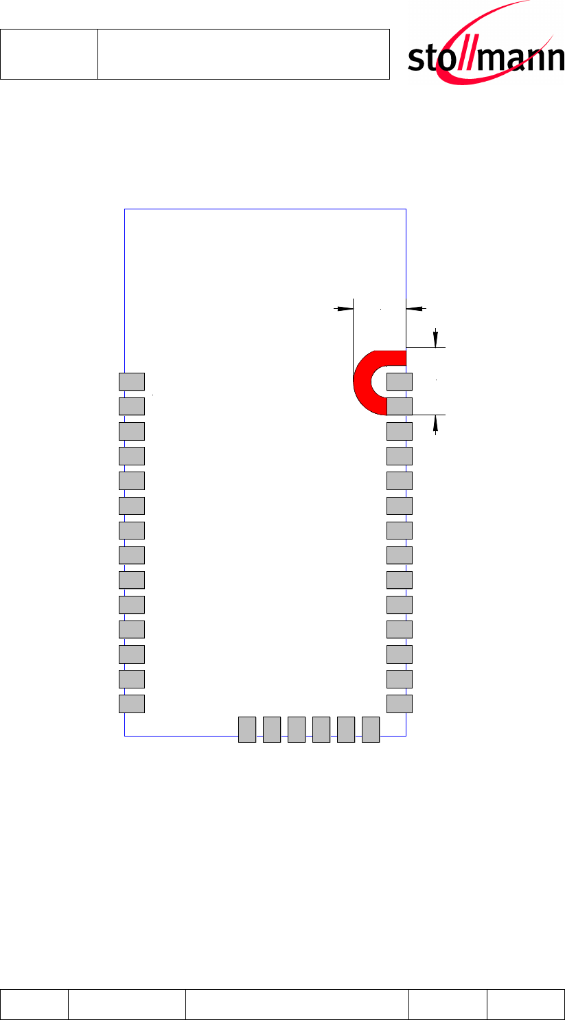
6.3 Re-flow Temperature-Time Profile
The data here is given only for guidance on solder and has to be adopted to your
process and other re-flow parameters for example the used solder paste. The paste
manufacturer provides a re-flow profile recommendation for his product.
Our used temp. profile
for reflow soldering
Temp
.[°C]
Time [s]
230°C -250°C max.
220°C
150°C – 190°C
90 ±30s
30 +20/-10s
Opposite side re-flow is prohibited due to module weight.
Devices will withstand the specified profile and will withstand up to 2 re-flows to a
maximum temperature of 260°C.
Stollmann
E + V GmbH
BlueMod+B20
Hardware reference
Author: bg Date of Saving: 28.03.07 Ref: BlueMod+B20_HWreference_V101.doc Revision: 1.00 Page 28 of 28
6.4 Restricted Area
The mother board should have no bare conductors or vias in this restricted area,
because it is not covered by stop mask print.
BlueMod+B20
top view
2,7
3,5
6.5 Housing Guidelines
The individual case must be checked to decide whether a specific housing is suit-
able for the use of the internal antenna. A plastic housing must at least fulfill the fol-
lowing requirements:
• Non-conductive material, non-RF-blocking plastics
• No metallic coating
• ABS is suggested

Stollmann
E + V GmbH
BlueMod+B20
Hardware reference
Author: bg Date of Saving: 28.03.07 Ref: BlueMod+B20_HWreference_V101.doc Revision: 1.00 Page 29 of 29
7 Safety Guidelines
8 Regulatory Information
8.1 Declaration of conformity
8.1.1 FCC Compliance
8.1.1.1 FCC Statement
This device complies with Part 15 of the FCC Rules and with RSS-210 of Industry
Canada.
Operation is subject to the following two conditions:
(1) this device my not cause harmful interference, and
(2) this device must accept any interference received, including interference
that may cause undesired operation.
8.1.1.2 Caution
Warning: Changes or modifications made to this equipment not expressly approved
by Stollmann Entwicklungs und Vertriebs may void the FCC authorization to operate
this equipment.
8.1.1.3 FCC Warning
This equipment has been tested and found to comply with the limits for a Class B
digital device, pursuant to Part 15 of the FCC Rules. These limits are designed to
provide reasonable protection against harmful interference in a residential installa-
tion. This equipment generates, uses and can radiate radio frequency energy and, if
not installed and used in accordance with the instructions, may cause harmful inter-
ference to radio communications. However, there is no guarantee that interference
will not occur in a particular installation. If this equipment does cause harmful inter-
ference to radio or television reception, which can be determined by turning the
equipment off and on, the user is encouraged to try to correct the interference by
one or more of the following measures:
• Reorient or relocate the receiving antenna.
• Increase the separation between the equipment and receiver.
• Connect the equipment into an outlet on a circuit different from that to which the
receiver is connected.
Consult the dealer or an experienced radio/TV technician for help.
Stollmann
E + V GmbH
BlueMod+B20
Hardware reference
Author: bg Date of Saving: 28.03.07 Ref: BlueMod+B20_HWreference_V101.doc Revision: 1.00 Page 30 of 30
The radiated output power of BlueMod+B20 is far below the FCC radio frequency
exposure limits. Nevertheless, the BlueMod+B20 shall be used in such a manner,
that the potential for human contact during normal operation is minimized.
8.1.1.4 RF-exposure Statement
The radiated output power of BlueMod+B20 is far below the FCC radio frequency
exposure limits. Nevertheless, the BlueMod+B20 shall be used in such a manner
that the potential for human body contact during normal operation is minimized.
Any notification to the end user of installation or removal instructions about the inte-
grated radio module is not allowed.
8.1.1.5 Labeling requirements for the End Product
Any End Product integrating the BlueMod+B20 must be labelled with at least the
following information:
This device contains transmitter with
FCC-ID: RFR-B2029
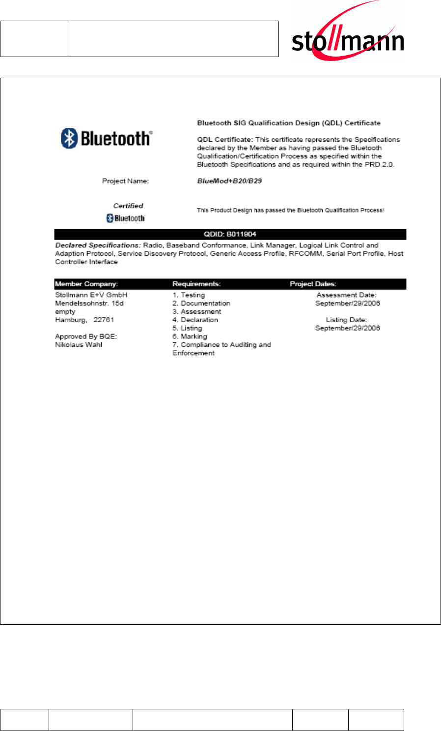
8.2 Bluetooth Qualification
The BlueMod+B20 is a qualified design according to the Bluetooth Qualification Pro-
gram Reference Document (PRD) V2.0. The Qualified Design ID (QDID) is:
B011904
For further information about marking requirements of your product attention should
be paid the Bluetooth Product Marking Guide at
https://programs.bluetooth.org/Download/Marking_Guide_20060601.pdf
Stollmann
E + V GmbH
BlueMod+B20
Hardware reference
Author: bg Date of Saving: 28.03.07 Ref: BlueMod+B20_HWreference_V101.doc Revision: 1.00 Page 31 of 31
Figure 8.1 Qualification Design Certificate
Stollmann
E + V GmbH
BlueMod+B20
Hardware reference
Author: bg Date of Saving: 28.03.07 Ref: BlueMod+B20_HWreference_V101.doc Revision: 1.00 Page 32 of 32
8.3 RoHS Declaration
Declaration of environmental compatibility for supplied products:
Hereby we declare to our best present knowledge based on declaration of our sup-
pliers that this product do not contain by now the following substances which are
banned by Directive 2002/95/EC (RoHS) or if contain a maximum concentration of
0,1% by weight in homogeneous materials for
Lead and lead compounds
Mercury and mercury compounds
Chromium (VI)
PBB (polybrominated biphenyl) category
PBDE (polybrominated biphenyl ether) category
And a maximum concentration of 0,01% by weight in homogeneous materials for
Cadmium and cadmium compounds
9 Related Documents
[1] CSR BlueCore4-External_Databook_BC417143B-db-001Pf.pdf
[2] Stollmann: AppNote_B0601_Antenna_Design_V1_0.pdf
10 Ordering Information
BlueMod+B20 is available in the following variants:
Name Antenna Article No.
BlueMod+B20/AI/SPP Internal 52621
BlueMod+B20/AP/SPP External 52741
11 Life Support Policy
This Stollmann product is not designed for use in life support appliances, devices, or
systems where malfunction can reasonably be expected to result in a significant
personal injury to the user, or as a critical component in any life support device or
system whose failure to perform can be reasonably expected to cause the failure of
the life support device or system, or to affect its safety or effectiveness. Stollmann
customers using or selling these products for use in such applications do so at their
own risk and agree to fully indemnify Stollmann for any damages resulting.
Stollmann
E + V GmbH
BlueMod+B20
Hardware reference
Author: bg Date of Saving: 28.03.07 Ref: BlueMod+B20_HWreference_V101.doc Revision: 1.00 Page 33 of 33
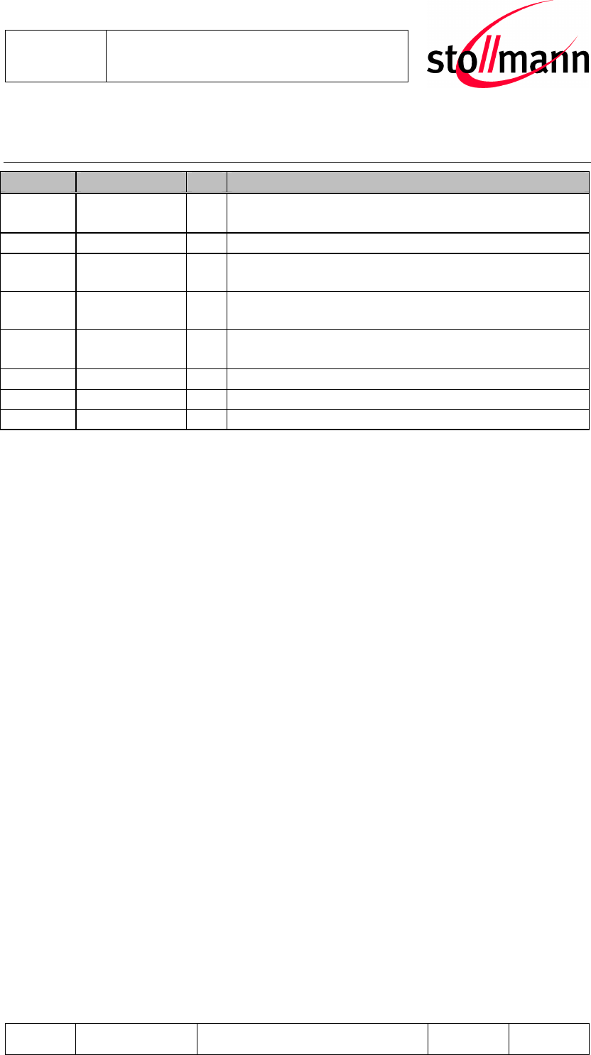
12 History
Version Release Date
By Change description
0.50 17.05.2006 GJ Correction: RESET# is active LOW
active LOW signal names end with # sign
0.60 23.05.2006 GJ Correction: AIO pinning
0.70 30.08.2006 BG/
JW
first combined version
BlueMod+B20/Bluemod+B29
0.90 06.03.2007 FH/
AA B29 removed,
1.00 12.03.2007 JW
Enhanced 8.2 Bluetooth Qualification
First non preliminary version
1.01 28.03.2007 JJ Ergänzungen Cetecom, Foto aktualsiert