Telit Wireless Solutions MS42 Bluetooth LE Module User Manual BlueMod S42 Hardware User Guide
Telit Wireless Solutions GmbH Bluetooth LE Module BlueMod S42 Hardware User Guide
User Manual

BlueMod+S42
Hardware User Guide
1VV0301303 Rev.3 – 2016-08-22


BlueMod+S42 Hardware User Guide
1VV0301303 Rev.3 – 2016-08-22
Reproduction forbidden without written authorization from Telit Communications S.p.A. - All Rights Reserved.
Page 3 of 62
SPECIFICATIONS SUBJECT TO CHANGE WITHOUT NOTICE
Notice
While reasonable efforts have been made to assure the accuracy of this document, Telit assumes no
liability resulting from any inaccuracies or omissions in this document, or from use of the information
obtained herein. The information in this document has been carefully checked and is believed to be
entirely reliable. However, no responsibility is assumed for inaccuracies or omissions. Telit reserves
the right to make changes to any products described herein and reserves the right to revise this
document and to make changes from time to time in content hereof with no obligation to notify any
person of revisions or changes. Telit does not assume any liability arising out of the application or use
of any product, software, or circuit described herein; neither does it convey license under its patent
rights or the rights of others.
It is possible that this publication may contain references to, or information about Telit products
(machines and programs), programming, or services that are not announced in your country. Such
references or information must not be construed to mean that Telit intends to announce such Telit
products, programming, or services in your country.
Copyrights
This instruction manual and the Telit products described in this instruction manual may be, include or
describe copyrighted Telit material, such as computer programs stored in semiconductor memories or
other media. Laws in the Italy and other countries preserve for Telit and its licensors certain exclusive
rights for copyrighted material, including the exclusive right to copy, reproduce in any form, distribute
and make derivative works of the copyrighted material. Accordingly, any copyrighted material of Telit
and its licensors contained herein or in the Telit products described in this instruction manual may not
be copied, reproduced, distributed, merged or modified in any manner without the express written
permission of Telit. Furthermore, the purchase of Telit products shall not be deemed to grant either
directly or by implication, estoppel, or otherwise, any license under the copyrights, patents or patent
applications of Telit, as arises by operation of law in the sale of a product.
Computer Software Copyrights
The Telit and 3rd Party supplied Software (SW) products described in this instruction manual may
include copyrighted Telit and other 3rd Party supplied computer programs stored in semiconductor
memories or other media. Laws in the Italy and other countries preserve for Telit and other 3rd Party
supplied SW certain exclusive rights for copyrighted computer programs, including the exclusive right
to copy or reproduce in any form the copyrighted computer program. Accordingly, any copyrighted
Telit or other 3rd Party supplied SW computer programs contained in the Telit products described in
this instruction manual may not be copied (reverse engineered) or reproduced in any manner without
the express written permission of Telit or the 3rd Party SW supplier. Furthermore, the purchase of Telit
products shall not be deemed to grant either directly or by implication, estoppel, or otherwise, any
license under the copyrights, patents or patent applications of Telit or other 3rd Party supplied SW,
except for the normal non-exclusive, royalty free license to use that arises by operation of law in the
sale of a product.

BlueMod+S42 Hardware User Guide
1VV0301303 Rev.3 – 2016-08-22
Reproduction forbidden without written authorization from Telit Communications S.p.A. - All Rights Reserved.
Page 4 of 62
Usage and Disclosure Restrictions
License Agreements
The software described in this document is the property of Telit and its licensors. It is furnished by
express license agreement only and may be used only in accordance with the terms of such an
agreement.
Copyrighted Materials
Software and documentation are copyrighted materials. Making unauthorized copies is prohibited by
law. No part of the software or documentation may be reproduced, transmitted, transcribed, stored in a
retrieval system, or translated into any language or computer language, in any form or by any means,
without prior written permission of Telit
High Risk Materials
Components, units, or third-party products used in the product described herein are NOT fault-tolerant
and are NOT designed, manufactured, or intended for use as on-line control equipment in the following
hazardous environments requiring fail-safe controls: the operation of Nuclear Facilities, Aircraft
Navigation or Aircraft Communication Systems, Air Traffic Control, Life Support, or Weapons
Systems (High Risk Activities"). Telit and its supplier(s) specifically disclaim any expressed or implied
warranty of fitness for such High Risk Activities.
Trademarks
TELIT and the Stylized T Logo are registered in Trademark Office. All other product or service names
are the property of their respective owners.
Third Party Rights
The software may include Third Party Right software. In this case you agree to comply with all terms
and conditions imposed on you in respect of such separate software. In addition to Third Party Terms,
the disclaimer of warranty and limitation of liability provisions in this License shall apply to the Third
Party Right software.
TELIT HEREBY DISCLAIMS ANY AND ALL WARRANTIES EXPRESS OR IMPLIED FROM
ANY THIRD PARTIES REGARDING ANY SEPARATE FILES, ANY THIRD PARTY
MATERIALS INCLUDED IN THE SOFTWARE, ANY THIRD PARTY MATERIALS FROM
WHICH THE SOFTWARE IS DERIVED (COLLECTIVELY “OTHER CODE”), AND THE USE OF
ANY OR ALL THE OTHER CODE IN CONNECTION WITH THE SOFTWARE, INCLUDING
(WITHOUT LIMITATION) ANY WARRANTIES OF SATISFACTORY QUALITY OR FITNESS
FOR A PARTICULAR PURPOSE.
NO THIRD PARTY LICENSORS OF OTHER CODE SHALL HAVE ANY LIABILITY FOR ANY
DIRECT, INDIRECT, INCIDENTAL, SPECIAL, EXEMPLARY, OR CONSEQUENTIAL
DAMAGES (INCLUDING WITHOUT LIMITATION LOST PROFITS), HOWEVER CAUSED
AND WHETHER MADE UNDER CONTRACT, TORT OR OTHER LEGAL THEORY, ARISING
IN ANY WAY OUT OF THE USE OR DISTRIBUTION OF THE OTHER CODE OR THE
EXERCISE OF ANY RIGHTS GRANTED UNDER EITHER OR BOTH THIS LICENSE AND THE
LEGAL TERMS APPLICABLE TO ANY SEPARATE FILES, EVEN IF ADVISED OF THE
POSSIBILITY OF SUCH DAMAGES.
Copyright © Telit Communications S.p.A. 2016.

BlueMod+S42 Hardware User Guide
1VV0301303 Rev.3 – 2016-08-22
Reproduction forbidden without written authorization from Telit Communications S.p.A. - All Rights Reserved.
Page 5 of 62
Contents
1 Introduction ................................................................................................................. 11
1.1 Scope ..................................................................................................................... 11
1.2 Audience ................................................................................................................ 11
1.3 Contact Information, Support ................................................................................. 11
1.4 Document Organization ......................................................................................... 12
1.5 Text Conventions ................................................................................................... 12
1.6 Related Documents ................................................................................................ 13
2 General Product Description ..................................................................................... 14
2.1 Feature Summary .................................................................................................. 14
2.2 Applications ............................................................................................................ 15
2.3 General Cable Replacement .................................................................................. 15
2.3.1 Industry ...................................................................................................................... 15
2.3.2 POS/Advertising ........................................................................................................ 15
2.3.3 Healthcare and Medical ............................................................................................. 15
2.3.4 Sports and Fitness ..................................................................................................... 15
2.3.5 Entertainment ............................................................................................................ 16
2.4 Block Diagram ........................................................................................................ 16
3 Application Interface .................................................................................................. 17
3.1 Power Supply ......................................................................................................... 17
3.1.1 Power-up Slew-Rate .................................................................................................. 18
3.2 Reset ...................................................................................................................... 18
3.3 Serial Interface ....................................................................................................... 19
3.3.1 4-Wire Serial Interface ............................................................................................... 21
3.3.2 UART Example Circuits ............................................................................................. 22
3.3.3 Baud Rate Deviation .................................................................................................. 23
3.3.4 Dynamic I/O Signal Type Changes depending on the UICP status ............................ 23
3.4 GPIO Interface ....................................................................................................... 24
3.5 I2C Interface ........................................................................................................... 24
3.6 SPI Serial Peripheral Interface ............................................................................... 26
3.7 Bluetooth Radio Interface ....................................................................................... 26
3.8 NFC Function ......................................................................................................... 26
3.8.1 NFCT Antenna Recommendations ............................................................................ 27

BlueMod+S42 Hardware User Guide
1VV0301303 Rev.3 – 2016-08-22
Reproduction forbidden without written authorization from Telit Communications S.p.A. - All Rights Reserved.
Page 6 of 62
3.8.2 Power Back feeding ................................................................................................... 27
3.9 Slow Clock Interface .............................................................................................. 28
3.9.1 32,768 kHz Crystal Oscillator Specification (32k XOSC) ............................................ 28
3.9.2 Connection of an External 32,768 kHz Crystal ........................................................... 28
3.10 Test Mode ........................................................................................................... 29
3.11 Operating in a Power-Switched Environment ..................................................... 30
3.12 Serial Wire Debug Interface ................................................................................ 30
3.13 DC/DC Converter ................................................................................................ 31
4 Module Pins ................................................................................................................ 32
4.1 Pin Numbering ....................................................................................................... 32
4.2 Pin Description ....................................................................................................... 33
4.2.1 General Pin Description ............................................................................................. 33
4.2.2 Application Specific Pin Description ........................................................................... 35
4.3 Handling of Unused Signals ................................................................................... 36
5 Electrical Characteristics ........................................................................................... 37
5.1 Absolute Maximum Ratings .................................................................................... 37
5.2 Operating Conditions ............................................................................................. 37
5.3 Environmental Requirements ................................................................................. 37
5.4 DC Parameter ........................................................................................................ 38
5.4.1 General Purpose I/O (GPIO) ...................................................................................... 38
5.4.2 EXT-RES# ................................................................................................................. 39
5.4.3 Analog Digital Converter (ADC) ................................................................................. 40
5.4.4 ADC Reference Voltage ............................................................................................. 40
5.4.5 Analog ADC Input AIN ............................................................................................... 41
5.5 Power Consumption and Power-Down Modes ....................................................... 42
5.5.1 Terminal I/O Configuration ......................................................................................... 42
5.6 RF Performance ..................................................................................................... 44
5.6.1 BLE Receiver ............................................................................................................. 44
5.6.2 BLE Transmitter ......................................................................................................... 45
5.6.3 Antenna-Gain and Radiation Pattern ......................................................................... 46
5.7 Power-Up Time ...................................................................................................... 47
6 Mechanical Characteristics ....................................................................................... 48
6.1 Dimensions ............................................................................................................ 48
6.2 Recommended Land Pattern ................................................................................. 49

BlueMod+S42 Hardware User Guide
1VV0301303 Rev.3 – 2016-08-22
Reproduction forbidden without written authorization from Telit Communications S.p.A. - All Rights Reserved.
Page 7 of 62
6.3 Re-flow Temperature-Time Profile ......................................................................... 49
6.4 Placement Recommendation ................................................................................. 50
6.5 Housing Guidelines ................................................................................................ 51
6.6 Antenna Issues ...................................................................................................... 51
6.7 Safety Guidelines ................................................................................................... 51
6.8 Cleaning ................................................................................................................. 51
7 Application Diagram ................................................................................................... 52
8 Compliances ............................................................................................................... 53
8.1 Declaration of Conformity CE ................................................................................. 53
8.2 FCC Compliance .................................................................................................... 53
8.2.1 FCC Grant ................................................................................................................. 53
8.2.2 FCC Statement .......................................................................................................... 53
8.2.3 FCC Caution .............................................................................................................. 54
8.2.4 FCC Warning ............................................................................................................. 54
8.2.5 FCC RF-exposure Statement ..................................................................................... 54
8.2.6 FCC Labeling Requirements for the End Product ...................................................... 55
8.3 IC Compliance ........................................................................................................ 55
8.3.1 IC Grant ..................................................................................................................... 55
8.3.2 IC Statement .............................................................................................................. 55
8.3.3 IC Caution .................................................................................................................. 56
8.3.4 IC RF-exposure Statement ........................................................................................ 56
8.3.5 IC Labeling Requirements for the End Product .......................................................... 56
8.3.6 IC Label Information BlueMod+S42 ........................................................................... 56
8.4 KCC Certification .................................................................................................... 57
8.4.1 KCC Certificate .......................................................................................................... 57
8.5 Bluetooth Qualification ........................................................................................... 57
8.6 RoHS Declaration .................................................................................................. 57
9 Packing ........................................................................................................................ 58
9.1 Tape ....................................................................................................................... 59
9.2 Reel ........................................................................................................................ 59
9.3 Package Label ....................................................................................................... 59
10 Ordering Information............................................................................................... 60
10.1 Part Numbers ...................................................................................................... 60

BlueMod+S42 Hardware User Guide
1VV0301303 Rev.3 – 2016-08-22
Reproduction forbidden without written authorization from Telit Communications S.p.A. - All Rights Reserved.
Page 8 of 62
10.2 Standard Packing Unit ........................................................................................ 60
10.3 Evaluation Kit ...................................................................................................... 60
11 Safety Recommendations ....................................................................................... 61
12 Document History ................................................................................................... 62

BlueMod+S42 Hardware User Guide
1VV0301303 Rev.3 – 2016-08-22
Reproduction forbidden without written authorization from Telit Communications S.p.A. - All Rights Reserved.
Page 9 of 62
Figures
Figure 1: BlueMod+S42/AI Block Diagram ...................................................................................... 16
Figure 2: BlueMod+S42 Example Power Supply with LDO ............................................................. 17
Figure 3: BlueMod+S42 Example Reset ......................................................................................... 18
Figure 4: Serial Interface Signals .................................................................................................... 20
Figure 5: Five Wire Interface supporting UICP (Minimum Signals needed) ..................................... 20
Figure 6: BlueMod+S42 Example Serial Interface (RS-232) Supporting UICP ................................ 22
Figure 7: BlueMod+S42 Example Serial Interface (Mixed Signal Level) .......................................... 22
Figure 8: BlueMod+S42 I2C Interface .............................................................................................. 25
Figure 9: BlueMod+S42 SPI Interface (Example: Master Mode) ..................................................... 26
Figure 10: BlueMod+S42 NFC Antenna Tuning .............................................................................. 27
Figure 11: BlueMod+S42 connection of external XTAL ................................................................... 29
Figure 12: BlueMod+S42 Pin Numbering (Top View) ...................................................................... 32
Figure 13: Typical Antenna Radiation Pattern at 2402MHz ............................................................. 46
Figure 14: Typical Antenna Radiation Pattern at 2441MHz ............................................................. 46
Figure 15: Typical Antenna Radiation Pattern at 2480MHz ............................................................. 46
Figure 16: BlueMod+S42/AI Dimensions ......................................................................................... 48
Figure 17: BlueMod+S42 Land Pattern TOP VIEW ......................................................................... 49
Figure 18: Soldering Temperature-Time Profile (For Reflow Soldering) .......................................... 49
Figure 19 : BlueMod+S42/AI Placement Recommendation ............................................................. 51
Figure 20: Typical Application Schematics ...................................................................................... 52
Tables
Table 1 Product Applicability ............................................................................................................. 2
Table 2: Power up Rise Time Requirements ................................................................................... 18
Table 3: Pin States during Reset ..................................................................................................... 19
Table 4: Deviation of Baud rates ..................................................................................................... 23
Table 5: 32,768kHz Crystal Oscillator ............................................................................................. 28
Table 6: Testmode# / Boot0 Logic................................................................................................... 29
Table 7: General Pin Assignment .................................................................................................... 34

BlueMod+S42 Hardware User Guide
1VV0301303 Rev.3 – 2016-08-22
Reproduction forbidden without written authorization from Telit Communications S.p.A. - All Rights Reserved.
Page 10 of 62
Table 8: Application Specific Pin Assignments, TIO ........................................................................ 36
Table 9: Absolute Maximum Ratings ............................................................................................... 37
Table 10: DC Operating Conditions ................................................................................................. 37
Table 11: Environmental Requirements .......................................................................................... 37
Table 12: DC Characteristics, Digital IO .......................................................................................... 38
Table 13: DC Characteristics, EXT-RES# ....................................................................................... 39
Table 15: Input Impedance for AIN.................................................................................................. 41
Table 16: Supply Current Sleep Modes, no Radio Activity .............................................................. 42
Table 17: Supply Current BLE Terminal I/O Profile, Peripheral Device Role ................................... 43
Table 18: RF Performance BLE Receiver ....................................................................................... 44
Table 19: RF Performance BLE Transmitter ................................................................................... 46

BlueMod+S42 Hardware User Guide
1VV0301303 Rev.3 – 2016-08-22
Reproduction forbidden without written authorization from Telit Communications S.p.A. - All Rights Reserved.
Page 11 of 62
1 Introduction
1.1 Scope
This document provides information how the BlueMod+S42/AI can be integrated into
customer systems. It addresses hardware specifications of the BlueMod+S42/AI and
requirements of the hardware environments for the BlueMod+S42/AI.
NOTE:
The description text “BlueMod+S42” refers to all modules listed in the Table 1 Product
Applicability
1.2 Audience
This document is intended for Telit customers, especially system integrators, about to
implement Bluetooth modules in their application.
1.3 Contact Information, Support
For general contact, technical support, to report documentation errors and to order manuals,
contact Telit Technical Support Center (TTSC) at:
TS-EMEA@telit.com
TS-NORTHAMERICA@telit.com
TS-LATINAMERICA@telit.com
TS-APAC@telit.com
or
TS-SRD@telit.com for global Bluetooth support
Alternatively, use:
http://www.telit.com/en/products/technical-support-center/contact.php
For detailed information about where you can buy the Telit modules or for recommendations
on accessories and components visit:
http://www.telit.com
To register for product news and announcements or for product questions contact Telit
Technical Support Center (TTSC).

BlueMod+S42 Hardware User Guide
1VV0301303 Rev.3 – 2016-08-22
Reproduction forbidden without written authorization from Telit Communications S.p.A. - All Rights Reserved.
Page 12 of 62
Our aim is to make this guide as helpful as possible. Keep us informed of your comments and
suggestions for improvements.
Telit appreciates feedback from the users of our information.
1.4 Document Organization
This document contains the following chapters:
“Chapter 1: “Introduction” provides a scope for this document, target audience, contact and
support information, and text conventions.
“Chapter 3: General Product Description” gives an overview of the features of the product.
“Chapter 3: Application Interface” describes in details the interfaces of the product.
“Chapter 4: Module Pins” describes the signal mapping and specification.
“Chapter 5: Electrical Characteristics” describes in details the characteristics of the product.
“Chapter 6: Mechanical Characteristics” describes the mechanical characteristics.
“Chapter 8: “Compliances” provides some fundamental information on conformity and
compliances.
“Chapter 11: “Safety Recommendation” provides some safety recommendations that must be
follow by the customer in the design of the application that makes use of the BlueMod+S42.
1.5 Text Conventions
Danger – This information MUST be followed or catastrophic equipment failure or bodily
injury may occur.
Caution or Warning – Alerts the user to important points about integrating the module, if
these points are not followed, the module and end user equipment may fail or malfunction.
Tip or Information – Provides advice and suggestions that may be useful when
integrating the module.
All dates are in ISO 8601 format, i.e. YYYY-MM-DD.

BlueMod+S42 Hardware User Guide
1VV0301303 Rev.3 – 2016-08-22
Reproduction forbidden without written authorization from Telit Communications S.p.A. - All Rights Reserved.
Page 13 of 62
1.6 Related Documents
• Nordic: nRF52_Series_Reference_Manual
• Nordic: nRF52832_PS v1.0.pdf (Product Specification)
• BlueMod+S42\Central AT Command Reference, 80512ST10771A
• BlueMod+S42 Software User Guide, 1VV0301318
• UICP_UART_Interface_Control_Protocol, 30507ST10756A
• BlueMod+S42 Testmode Reference, 80512NT11496A
• Bluetooth SIG Core Specification V4.2

BlueMod+S42 Hardware User Guide
1VV0301303 Rev.3 – 2016-08-22
Reproduction forbidden without written authorization from Telit Communications S.p.A. - All Rights Reserved.
Page 14 of 62
2 General Product Description
2.1 Feature Summary
Bluetooth specification V4.2 compliant
Supports Bluetooth low energy
Fully qualified Bluetooth V4.2 Single Mode LE
CE certified
FCC and IC certified
Nordic nRF52832 inside
Fast Connection Setup
RF output power -20 up to +4dBm EIRP
RF output power -40dBm EIRP in Whisper Mode
RSSI detector on board
High sensitivity design
Supply voltage range 1,7V to 3,6V
Internal crystal oscillator (32 MHz)
LGA Surface Mount type. BlueMod+S42: 17 x 10 x 2.6 mm3
Pin compatible to Telit BlueMod+S BLE and BlueMod+SR dual mode module
Shielded to be compliant to FCC full modular approval
Flexible Power Management
128-bit AES encryption
NFC peripheral communication signal interface type A with 106 kbps bit rate
High-speed UART interface
I2C Master
SPI Master/Slave interface
Low power comparator
Real Time Counter
Up to 19 digital IO’s for individual usage by embedded software
Up to 8 analog inputs for individual usage by embedded software
8/9/10bit ADC
Arm® CortexTM-M4 core for embedded profiles or application software
Manufactured in conformance with RoHS2
Operating temperature -40 ... +85 °C
Weight: 0,7 g

BlueMod+S42 Hardware User Guide
1VV0301303 Rev.3 – 2016-08-22
Reproduction forbidden without written authorization from Telit Communications S.p.A. - All Rights Reserved.
Page 15 of 62
2.2 Applications
The BlueMod+S42 is designed to be used in low power applications, like sensor devices.
Some typical applications are described in this chapter.
Supported profiles are:
• Terminal I/O
• GATT based LE-profiles
NOTE:
Support for any additional profile is possible on request
2.3 General Cable Replacement
In case there is no standardized application specific profile available the BlueMod+S42 offers
Telit’s Terminal I/O profile, which allows transparent data transfer over UART and supports
Secure Simple Pairing, making the pairing process easy and the connection secure. Terminal
I/O is available for iOS and Android as well as implemented in Telit’s dual mode module
BlueMod+SR.
2.3.1 Industry
BlueMod+S42 can be used to monitor and control motors, actuators, values and entire
processes.
2.3.2 POS/Advertising
BlueMod+S42 supports iBeacon or similar applications.
2.3.3 Healthcare and Medical
Usage of Bluetooth is aimed mainly at devices that are used for monitoring vital data. Typical
devices are blood glucose meter, blood pressure cuffs and pulse ox meters. Bluetooth
BR/EDR and low energy were chosen by the Continua Health Alliance as transports for
interoperable end to end communication.
2.3.4 Sports and Fitness
In the sports and fitness segment the BlueMod+S42 is used in devices for positioning as well
as monitoring vital data. Typical devices in this market are heart rate monitors, body
temperature thermometers, pedometers, cadence meters, altimeter, positioning / GPS tracking
and watches displaying information from sensors.
BlueMod+S42 Hardware User Guide
1VV0301303 Rev.3 – 2016-08-22
Reproduction forbidden without written authorization from Telit Communications S.p.A. - All Rights Reserved.
Page 16 of 62
2.3.5 Entertainment
Bluetooth technology is already used in a wide variety of devices in the entertainment sector,
namely set-top boxes / gaming consoles. BlueMod+S42 is especially suited for use in remote
controls, gaming controller and wireless mouse/keyboard applications.
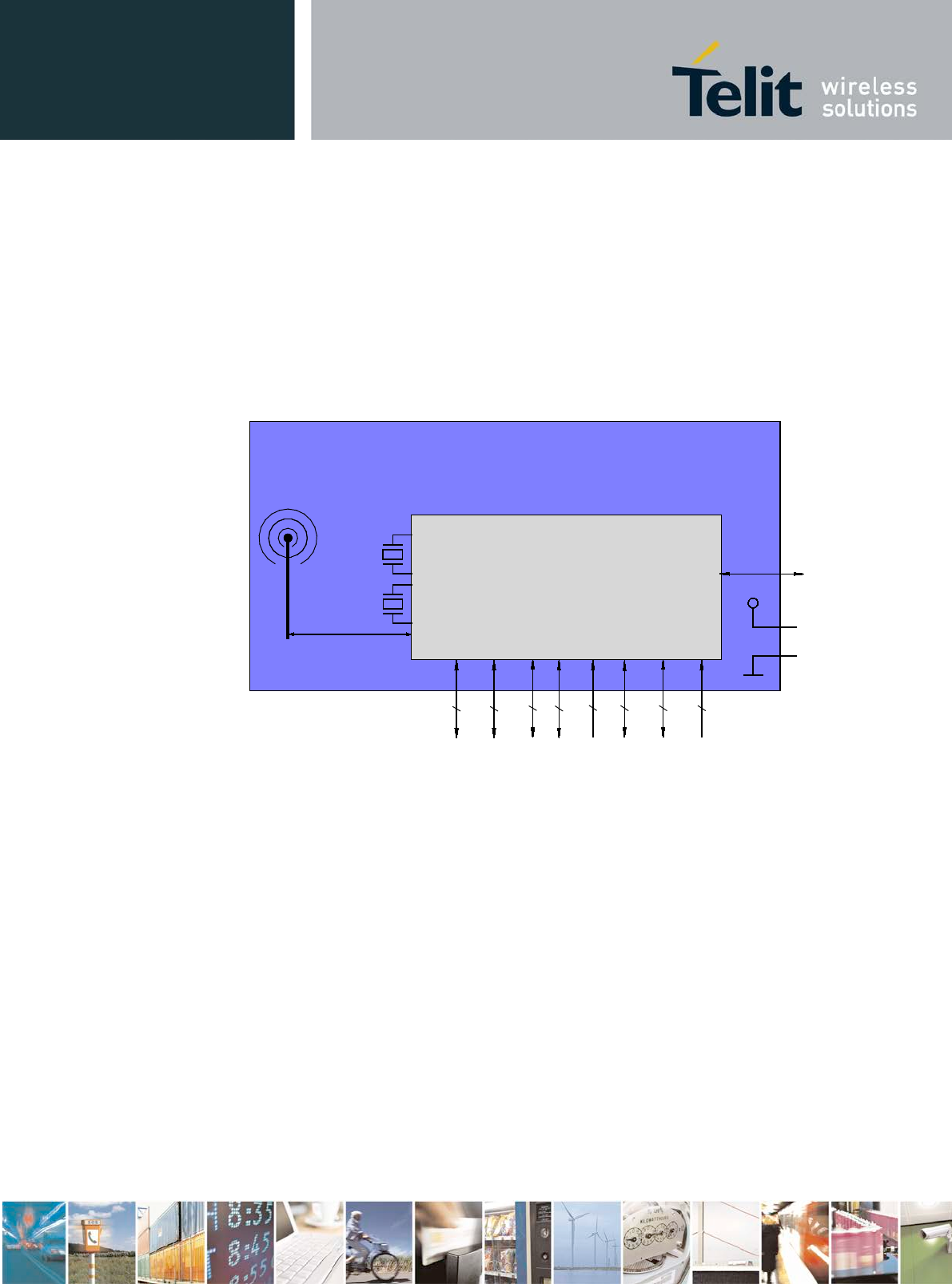
2.4 Block Diagram
nRF52832
VSUP
BlueMod+S42/AI
RESET
I2C
UART
SPI
1
2
up to 7
3
GND
3.0V
32MHz
opt. 32kHz
Serial Wire Debug
onboard
antenna
2
GPIO
up to 19
Analog In
up to 6
NFC-Antenna
2
32,768kHz
optional
Figure 1: BlueMod+S42/AI Block Diagram

BlueMod+S42 Hardware User Guide
1VV0301303 Rev.3 – 2016-08-22
Reproduction forbidden without written authorization from Telit Communications S.p.A. - All Rights Reserved.
Page 17 of 62
3 Application Interface
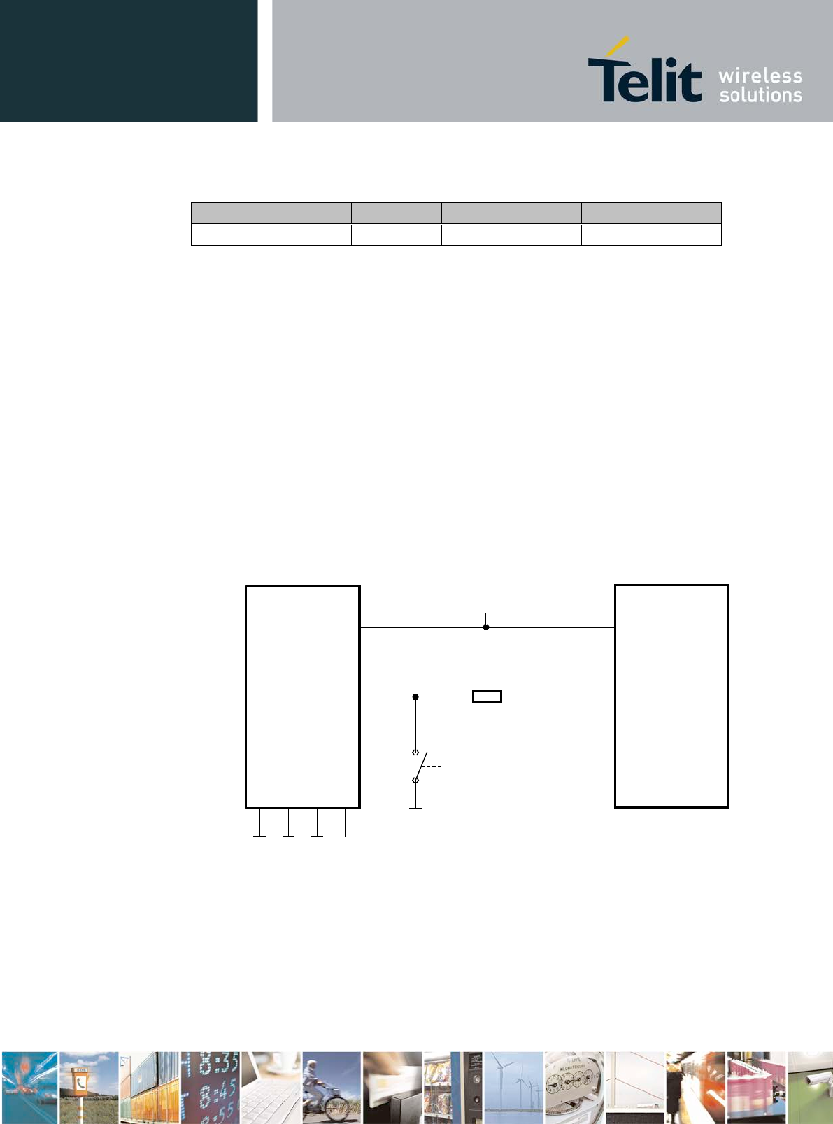
3.1 Power Supply
BlueMod+S42 require a power supply with the following characteristics:
Typical: 3,0VDC, min.: 1,7VDC, max.: 3,6VDC, thereby delivering > 25 mA peak
BlueMod+S42 is designed to be powered from 3V coin cell batteries e.g. CR2032 directly, or
any other power source complying with the given requirements. For optimal performance, a
stable supply is recommended. Furthermore, it is recommended to place a capacitor in parallel
to the CR2032 3V coin cell battery in order to prolong battery lifetime, by compensating the
effects of the rising source resistance of the battery to pulsed loads. Since the isolation
resistance of this capacitor will discharge the battery in a not insignificant scale, the capacitor
should be chosen under consideration of the following rules:
• capacitance as small as necessary
• nominal voltage as high as possible
• case size as large as possible
• use X7R instead of X5R
In case of using an NFC antenna in conjunction with batteries attend to chapter 3.7.1 Power
Back feeding.
BlueMod+S42
XC6209F-3.3
E-6,F-6
VSUP
GND:
A-7,E-7,F-7,B-[5:8],
C-[5:8],D-8,E-8,F-8
1µ + 100n
1µ
VOUT
VSS
VIN
CE
5 1
3
2
+5VDC
Figure 2: BlueMod+S42 Example Power Supply with LDO
BlueMod+S42 Hardware User Guide
1VV0301303 Rev.3 – 2016-08-22
Reproduction forbidden without written authorization from Telit Communications S.p.A. - All Rights Reserved.
Page 18 of 62
3.1.1 Power-up Slew-Rate
Parameter Min Max Unit
VSUP rise time rate
(1)
0 60 ms
(1) 0V to 1,7V
Table 2: Power up Rise Time Requirements
3.2 Reset
BlueMod+S42 are equipped with circuitry for generating reset from three sources:
• A reset is held active, when VSUP falls below the threshold of the brownout detector
(VBOR = 1,2V … 1,7V), and is released when VSUP rises above VBOR + VHYST .
The brownout detector also holds the reset active during power up, until VSUP >
VBOR.
• A reset is generated, when VSUP is > VBOR and increases 300 mV or more, within
300 ms or less.
• By holding pin B-1 (EXT-RES#) at ≤ VSUP*0,3V for tHOLDRESETNORMAL ≥ 0,2µs, an
external reset (pin reset) is generated. This pin has a fixed internal pull-up resistor
(RPU = 11kΩ ... 16kΩ). EXT-RES# may be left open if not used.
BlueMod+S42
E-6,F-6
VSUP
GND
+3V3
EXT-RES# B-1
Reset-Switch is optional
Please Note: EXT-RES# of BlueMod+S42 has approx. 13k internal pullup.
470R*
Reset signal is optional
Host MCU
GPIO
VDD
* resistor can be omitted,
if GPIO is open drain type
Figure 3: BlueMod+S42 Example Reset
The following table shows the pin states of BlueMod+S42 during reset active.

BlueMod+S42 Hardware User Guide
1VV0301303 Rev.3 – 2016-08-22
Reproduction forbidden without written authorization from Telit Communications S.p.A. - All Rights Reserved.
Page 19 of 62
Pin Name State: BlueMod+S42
EXT-RES# Input with pull-up
(1)
XL-IN Input floating (disconnected)
XL-OUT Input floating (disconnected)
UART-TXD Input floating (disconnected)
UART-RXD Input floating (disconnected)
UART-RTS# Input floating (disconnected) with pull-up resistor 470kΩ
(2)
UART-CTS# Input floating (disconnected)
IUR-OUT# Input floating (disconnected)
IUR-IN# Input floating (disconnected)
GPIO[0:14] Input floating (disconnected)
TESTMODE# Input floating (disconnected)
BOOT0 Input floating (disconnected)
SWDIO Input with pull-up
(1)
SWCLK Input with pull-down
(1)
(1) pull-up, pull-down: RPU, RPD is typ. 13kΩ (11kΩ to 16kΩ)
(2) a discrete resistor is used
Table 3: Pin States during Reset
The pin states as indicated in Table 3 are kept until hardware initialization has started.
3.3 Serial Interface
The serial interface of BlueMod+S42 is a high-speed UART interface supporting RTS/CTS
flow control and interface-up/down mechanism according to the UICP+ protocol (refer to
UICP_UART_Interface_Control_Protocol, 30507ST10756A). Electrical interfacing is at
CMOS levels (defined by VSUP; see chapter 5.4.1).
Transmission speeds are 9600 – 921600 bps and 1Mbps (asynchronous)
Character representation: 8 Bit, no parity, 1 stop bit (8N1)
Hardware flow-control with RTS and CTS (active low)
NOTE:
Transmission speed may be limited by firmware. See corresponding command reference
BlueMod+S42\Central AT Command Reference for further information.
BlueMod+S42 Hardware User Guide
1VV0301303 Rev.3 – 2016-08-22
Reproduction forbidden without written authorization from Telit Communications S.p.A. - All Rights Reserved.
Page 20 of 62
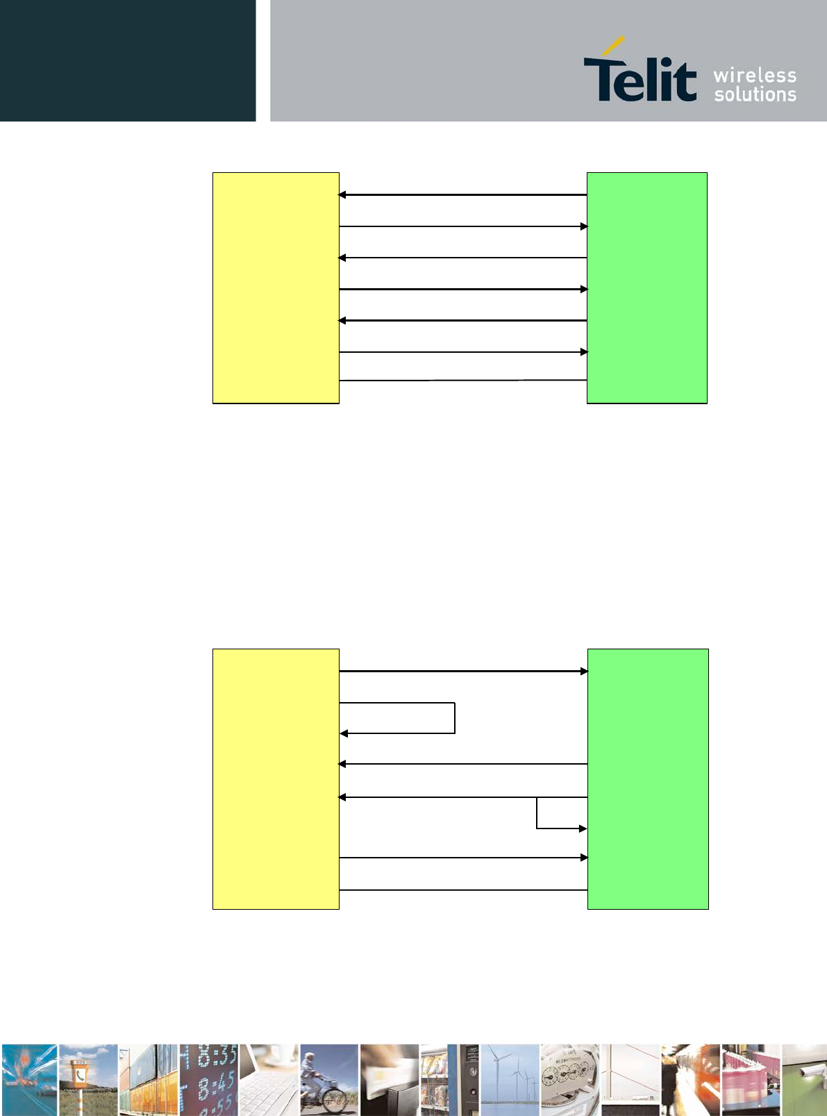
BlueMod+S42
Host
UART-RXD
UART-TXD
UART-CTS#
UART-RTS#
IUR-IN#
IUR-OUT#
GND
Figure 4: Serial Interface Signals
The basic serial interface (with RTS/CTS flow control) uses only four signal lines (UART-
RXD, UART-TXD, UART-CTS#, UART-RTS#) and GND. IUR-IN#, IUR-OUT# and
GPIO[4] (see below) can be left unconnected.
A substantially saving of power during idle phases can be achieved (see 5.5.1) when the UICP
protocol is used (refer to UICP_UART_Interface_Control_Protocol, 30507ST10756A). This
protocol should be implemented on the host side as well. Signals IUR-IN# and IUR-OUT#
should be connected to the host (see Figure 4: Serial Interface
Signals) and may be mapped to DSR and DTR, if an RS232-style (DTE-type) interface is
used (see Figure 6).
BlueMod+S42
Host
UART-TXD
IUR-OUT#
UART-CTS#
UART-RXD
IUR-IN#
UART-RTS#
IUR-OUT#
IUC-IN#
CTS#
TXD
RXD
GND
GND
Figure 5: Five Wire Interface supporting UICP (Minimum Signals needed)
Figure 5 shows the minimal configuration to use UICP for both directions RxD and TxD. To
use this scheme, the user has to implement UICP on host side for the transmitter only to wake
up the BlueMod+S42 receiver.

BlueMod+S42 Hardware User Guide
1VV0301303 Rev.3 – 2016-08-22
Reproduction forbidden without written authorization from Telit Communications S.p.A. - All Rights Reserved.
Page 21 of 62
When using the TIO firmware and applications, call control can be supported by GPIO[4].
Driving GPIO[4] to logic High level during a data transfer phase will “hang up” the
connection and disconnect the Bluetooth link. This signal may be mapped to DSR, if an
RS232-style (DTE-type) interface is used. Please refer to BlueMod+S42\Central AT
Command Reference for a functional specification. GPIO[4] can be left unconnected if this
feature is not used.
3.3.1 4-Wire Serial Interface
If the host in question is sufficiently fast, a four-wire scheme may be successful. Connect the
serial lines UART-RXD, UART-TXD as well as UART-RTS# and GND; leave UART-CTS#
open. The host is required to stop sending data within a short time after de-assertion of
UART-RTS# (there is room for up to 4 more characters at the time RTS# drops).
Attention: UICP has to be deactivated permanently in this configuration, because signal
UART-CTS# and IUR-IN# become inputs with no PU or PD if UICP is active. This would
cause floating CMOS inputs.
NOTE:
It is strongly recommended to use hardware flow control in both directions. Not using flow
control can cause a loss of data.
BlueMod+S42 Hardware User Guide
1VV0301303 Rev.3 – 2016-08-22
Reproduction forbidden without written authorization from Telit Communications S.p.A. - All Rights Reserved.
Page 22 of 62
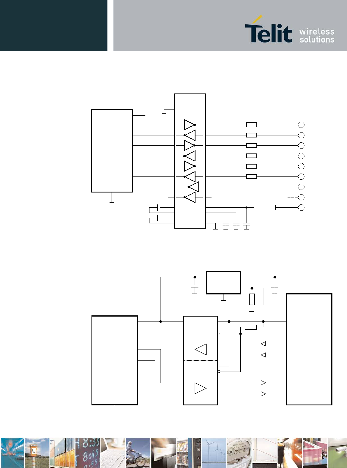
3.3.2 UART Example Circuits
2
BlueMod+S42
GND
MAX3241
14
+3V3
22
23
2
3
7
8
4
6
1
9
TXD
RXD
RTS#
CTS#
IUR-OUT#
IUR-IN#
TXD
RXD
RTS
CTS
DTR
DSR
DCD
RI
RS232
DSUB9 (male)
DTE style connector pinout
9
4
10
5
11
6
7
8
19
13
18
12
17
16
15
F-4
D-2
D-7
F-3
B-4
D-5
UART_TXD
UART_RXD
UART_RTS#
UART_CTS#
IUR-OUT#
IUR-IN#
SHDN#
EN#
100n
100n
28
24
1
+3V3
100n 100n 100n
26
3
27
25
V+
VCC
V -
GND
C2+
C2-
C1+
C1-
220R
220R
220R
220R
220R
220R
5
SigGND
can be left open
VSUP
+3V3
Figure 6: BlueMod+S42 Example Serial Interface (RS-232) Supporting UICP
VDDIO
(+1.2V .. +3.6V)
BlueMod+S42
GND
D-2
F-4
F-3
D-7
UART_RXD
UART_TXD
UART_CTS#
UART_RTS#
10µ+100n+1n
SN74AVC4T245
User Host System
VSUP
XC6209F-3.3
VOUT
VSS
VIN
CE 1µ
100k
100k
VCCB
1B1
1B2
2B1
2B2 2A2
2A1
1A2
1A1
VCCA
1DIR
1OE
2DIR
2OE
(GPIO, Out,
no pu/pd)
(GPIO, Out,
no pu/pd)
TXD
RTS#
RXD
CTS#
+5VDC
OE_DRV#
BT_ENABLE
VDD_HOST (+1.2 .. +3.6V)
+3V3_switched
Figure 7: BlueMod+S42 Example Serial Interface (Mixed Signal Level)
BlueMod+S42 Hardware User Guide
1VV0301303 Rev.3 – 2016-08-22
Reproduction forbidden without written authorization from Telit Communications S.p.A. - All Rights Reserved.
Page 23 of 62
3.3.3 Baud Rate Deviation
The following table shows the deviation in percent of the standard data rates. The deviation
may be caused by the inaccuracy of the crystal oscillator or granularity of the baud rate
generator.
Baud
Rate
nominal
Baud
Rate
actual
Deviation
[%]
9600 9598 -0,02
14400 14401 0,01
19200 19208 0,04
28800 28777 -0,08
38400 38369 -0,08
57600 57554 -0,08
76800 76923 0,16
115200 115108 -0,08
230400 231884 0,64
250000 250000 0,00
460800 457143 -0,79
921600 921176 -0,05
Table 4: Deviation of Baud rates
Note: The total deviation of sender and receiver shall not exceed 2.5% to prevent
loss of data.
3.3.4 Dynamic I/O Signal Type Changes depending on the UICP
status
In order to allow customers to use the serial interface with the minimal signal count on the
one side and to reduce current consumption when using UICP on the other side, the
BlueMod+S42 FW supports the following dynamic I/O signal type changes depending on the
UICP activated resp. deactivated status.

BlueMod+S42 Hardware User Guide
1VV0301303 Rev.3 – 2016-08-22
Reproduction forbidden without written authorization from Telit Communications S.p.A. - All Rights Reserved.
Page 24 of 62
Signal UICP deactivated UICP activated
UART-CTS# I-PD I-FLOAT
IUR-IN# I-DIS I-FLOAT
IUR-OUT# I-DIS O-PP
Legend: I-PD = Input with pull-down resistor, I-DIS = Input disconnected,
I-FLOAT = input floating, O-PP = Output push-pull
Signal types I-PD, I-DIS and O-PP may be left open. I-FLOAT has to be driven to GND or
VCC to avoid open CMOS input oscillation.
If UICP is deactivated the pull-down resistor on UART-CTS# helps to keep the serial
interface active if UART-CTS# is open.
If UICP is active and the serial interface is down, UART-CTS# has to be held at VCC and
thus the pull-down would cause an unwanted permanent current drain. Therefore the pull-
down is switched off in this mode.
3.4 GPIO Interface
It is possible to use the programmable digital I/Os GPIO[0:14] on the BlueMod+S42. Their
behavior has to be defined project specific in the firmware.
Unused GPIO pins shall be left unconnected to stay compatible. There may be functions
assigned to some in future versions of the firmware.
3.5 I2C Interface1
The I2C bus interface serves as an interface between the internal microcontroller and the serial
I2C bus. BlueMod+S42 is the master and controls all I2C bus specific sequencing, protocol
and timing. It supports standard (100kHz) and fast (400kHz) speed modes. The
BlueMod+S42 as an I2C master must be the only master of the I2C bus (no multimaster
capability). Clock stretching is supported.
GPIO[1]/I2C-SDA and GPIO[0]/I2C-SCL can be used to form an I2C interface. It is required
to connect 4k7 pull-up resistors on I2C-SCL and I2C-SDA when this interface is used.
1 subject to firmware support, contact Telit for current status

BlueMod+S42 Hardware User Guide
1VV0301303 Rev.3 – 2016-08-22
Reproduction forbidden without written authorization from Telit Communications S.p.A. - All Rights Reserved.
Page 25 of 62
I2C-SCL
I2C-SDA
GPIO[0]/I2C-SCL
GPIO[1]/I2C-SDA
BlueMod+S42
VSUP
Rpu
+3.3V
B-2
D-3
E-6,F-6
+3.3V
Rpu
+3.3V
4k7
4k7
Figure 8: BlueMod+S42 I2C Interface
BlueMod+S42 Hardware User Guide
1VV0301303 Rev.3 – 2016-08-22
Reproduction forbidden without written authorization from Telit Communications S.p.A. - All Rights Reserved.
Page 26 of 62
3.6 SPI Serial Peripheral Interface
The serial peripheral interface (SPI) allows for full-duplex, synchronous, serial
communication with external devices. The interface can be configured as the master and then
provides the communication clock (SCK) to the external slave device(s), or as the slave. The
SPI Interface supports SPI-modes 0 through 3. Module pins are used as follows:
• GPIO[2]: SPI-MOSI
• GPIO[5]: SPI-MISO
• GPIO[8]: SPI-SCK
GPIO[8]/SPI-SCK
GPIO[2]/SPI-MOSI
BlueMod+S42
E-2
SPI-Master
connected device
SPI-Slave
GPIO[5]/SPI-MISO
D-1
F-2
SCK, SPI_CLK
SDI, MOSI
SDO, MISO
typical signals:
Figure 9: BlueMod+S42 SPI Interface (Example: Master Mode)
3.7 Bluetooth Radio Interface
The BlueMod+S42/AI includes an integrated ceramic antenna.
3.8 NFC Function
The NFCT peripheral supports communication signal interface type A and 106 kbps bit rate
from the NFC Forum.
With appropriate software, the NFC peripheral can be used to emulate the listening device
NFC-A as specified by the NFC Forum.
Main features for the NFC peripheral:
• NFC-A listen mode operation
• 13.56 MHz input frequency
• Bit rate 106 kbps
• Wake-on-field low power field detection (SENSE) mode
• Frame assemble and disassemble for the NFC-A frames specified by the NFC Forum
• Programmable frame timing controller
BlueMod+S42 Hardware User Guide
1VV0301303 Rev.3 – 2016-08-22
Reproduction forbidden without written authorization from Telit Communications S.p.A. - All Rights Reserved.
Page 27 of 62
• Integrated automatic collision resolution, CRC and parity functions
3.8.1 NFCT Antenna Recommendations
The NFCT antenna coil must be connected differential between NFCANT1 and NFCANT2
pins of BlueMod+S42.
Two external capacitors Ctune1/2 connected between the NFCANTx pins and GND should be
used to tune the resonance of the antenna circuit to 13.56 MHz.
NFCANT1
BlueMod+S42
A-3
NFCANT2
A-4
C
tune1
C
tune2
C
p1
C
p2
C
int2
C
int1
NFC-Antenna
Figure 10: BlueMod+S42 NFC Antenna Tuning
= 2
(2×13,56)×
= =
= = ( )
=== 4
3.8.2 Power Back feeding
If the NFC antenna is exposed to a strong NFC field, power back feeding may occur. That
means, current may flow in the opposite direction on the supply due to parasitic diodes and
ESD structures.
If a battery is used that does not tolerate return current, a series diode must be placed between
the battery and the BlueMod+S42 in order to protect the battery. An ultra-low forward voltage
schottky diode should be chosen to keep the battery life reduction as small as possible.

BlueMod+S42 Hardware User Guide
1VV0301303 Rev.3 – 2016-08-22
Reproduction forbidden without written authorization from Telit Communications S.p.A. - All Rights Reserved.
Page 28 of 62
3.9 Slow Clock Interface
Even though an external slow clock is not required for BLE operation, consumption of power
during power-down modes can be reduced by connecting an XTAL (32,768kHz) and two
capacitors C1, C2 at pins XL-IN and XL-OUT.
3.9.1 32,768 kHz Crystal Oscillator Specification (32k XOSC)
Symbol Item Condition Limit Unit
Min Typ Max
fNOM Crystal Frequency Tamb = 25°C 32,768 kHz
fTOL Frequency Tolerance for
BLE applications including temperature
and aging (1) +/-250 ppm
CL Load Capacitance 12,5 pF
C0 Shunt Capacitance 2 pF
RS Equivalent Series
Resistance 100 kΩ
PD Drive Level 1 µW
Cpin Input Cap. On XL-IN and
XL-OUT 4 pF
(11) adjust crystal frequency by choosing correct value for C1, C2 (value depends on CL of
crystal and layout)
Table 5: 32,768kHz Crystal Oscillator
The module’s firmware will detect the presence of a slow clock during the boot process and
switch behavior appropriately.
3.9.2 Connection of an External 32,768 kHz Crystal
Connect the 32,768 kHz crystal and two capacitors C1, C2 at pins A-6 (XL-IN) and A-5 (XL-
OUT). The crystal has to comply with specifications given in Table 5. The exact value of
C1 and C2 depends on the crystal and the stray capacitance of the layout. Select C1, C2 such
that the slow clock oscillator operates at the exact frequency at room temperature (25°C). C1
and C2 shall be of equal capacity. The crystal and the capacitors shall be located as close as
possible to pins A-5, A-6.

BlueMod+S42 Hardware User Guide
1VV0301303 Rev.3 – 2016-08-22
Reproduction forbidden without written authorization from Telit Communications S.p.A. - All Rights Reserved.
Page 29 of 62
CL = (C1+Cpin+Cs) * (C2+Cpin+Cs) / (C1+C2+2*Cpin+2*Cs), or
C1, C2 = (2*CL – Cpin – Cs)
Cpin: see Table 5
Cs: stray capacitance, depends on layout
Figure 11: BlueMod+S42 connection of external XTAL
3.10 Test Mode
For homologation purposes the ability of test mode operation like “BlueMod+S42_Testmode”
or “Direct two wire UART Testmode” (DTM) is mandatory. The Direct Test Mode (as
defined by the Bluetooth SIG) and BlueMod+S42_Testmode are part of the BlueMod+S42
TIO-Firmware. Please refer to tbd.
For enabling the different test modes the BlueMod+S42 provides two IO pins.
• The pin Testmode is low active. Active in the following table means connect to GND.
• The pin Boot0 is high active. Active in the following table means connect to VDD.
• The other two combinations start the bootloader for firmware update of the
programmed firmware. These two modes are not scope of this document.
Table 6 shows the possible combinations:
Testmode#
Boot0
Mode
Active Inactive Testmode
Active Active DTM
Inactive Active Start Bootloader
Inactive Inactive Firmware Update
Table 6: Testmode# / Boot0 Logic
XL-IN
BlueMod+S42
A-6
Slow Clock
XL-OUT
A-5
32,768kHz
CL: 9pF
C1
C2
C1, C2 ~ 12pF

BlueMod+S42 Hardware User Guide
1VV0301303 Rev.3 – 2016-08-22
Reproduction forbidden without written authorization from Telit Communications S.p.A. - All Rights Reserved.
Page 30 of 62
To enter and use BlueMod+S42 Testmode or DTM, access to the following signals is
required:
• BOOT0
• TESTMODE#
• UART-RXD
• UART-TXD
• UART-RTS#
• UART-CTS#
• GND
These pins shall be routed to some test pads on an outer layer, but can be left open during
normal operation when not used.
Please note the UART is required for operation of test modes. During the homologation
process, UART-RXD, UART-TXD, UART-RTS# and UART-CTS# must be freely
accessible.
3.11 Operating in a Power-Switched Environment
A potential “back feeding” problem may arise, if the module is operated in an environment
where its power supply (VSUP) is switched off by the application. This might be done to save
some power in times Bluetooth is not needed.
As stated in Table 9, the voltage on any I/O pin must not exceed VSUP
by more than 0,3V at any time. Otherwise some current IINJ flows through the internal
protection diodes. This may damage the module (please refer to chapter 5.1 for limits).
There is no problem if the application circuit design and programming can assure that all
signals directed towards BlueMod+S42are set to low (U < 0,3V) before and while VSUP is
turned off. If this is not guaranteed, at least a series resistor (about 1k) must be inserted into
each signal path. This does protect the module but obviously cannot prevent from an
unwanted, additional current flow in case of such signal being at high-level. It may be
necessary to use driver chips in such applications, that gate off these signals while VSUP is
not present.
3.12 Serial Wire Debug Interface
The Serial Wire Debug (SWD) interface (signals SWDIO, SWCLK) is normally not used in a
customer’s product. It is reserved for debugging purposes.
Leave SWDIO, SWCLK unconnected. Only if you intend to use them for debugging
purposes, make them available.

BlueMod+S42 Hardware User Guide
1VV0301303 Rev.3 – 2016-08-22
Reproduction forbidden without written authorization from Telit Communications S.p.A. - All Rights Reserved.
Page 31 of 62
3.13 DC/DC Converter
The BlueMod+S42 contains a buck DC/DC converter and an LDO for supplying the radio
circuit.
Switching between DC/DC converter and LDO is done automatically based on load to
maximize efficiency.
Used with a 3V coin-cell battery, the peak current drawn from the battery is reduced by at
least 25% by use of the DC/DC converter.

BlueMod+S42 Hardware User Guide
1VV0301303 Rev.3 – 2016-08-22
Reproduction forbidden without written authorization from Telit Communications S.p.A. - All Rights Reserved.
Page 32 of 62
4 Module Pins
4.1 Pin Numbering
F1
E1
D1
C1
B1
A1 A2 A3 A4 A5 A6 A7 A8
F2
E2
D2
C2
B2
F3
E3
D3
C3
B3
F4
E4
D4
C4
B4
F5
E5
D5
C5
B5
F6
E6
D6
C6
B6
F7
E7
D7
C7
B7
F8
E8
D8
C8
B8
Figure 12: BlueMod+S42 Pin Numbering (Top View)
BlueMod+S42 Hardware User Guide
1VV0301303 Rev.3 – 2016-08-22
Reproduction forbidden without written authorization from Telit Communications S.p.A. - All Rights Reserved.
Page 33 of 62
4.2 Pin Description
4.2.1 General Pin Description
Type: PU – pull-up; PD – pull-down; PWR – Power; I – Input; O – Output; I/O – bidir.; OD – open drain; PP – push/pull;
RF: RadioFreq; I-DIS – Input Buffer Disconnected
Pin Name Signal Type Act Function Alternate Function Notes
E-6
VSUP1
PWR
+3,0V nom.
F-6
VSUP2
PWR
+3,0V nom
C-1
not connected
none
A-7, E-7, F-7,
B-[5,6,7,8],
C-[5,6,7,8],
D-8, E-8, F-8
GND PWR Ground
All GND pins must be connected
A-8
ANT PIN
none
reserved for ext. antenna
(4,9)
B-1
EXT-RES#
I-PU
L
User Reset
A-6
XL-IN
I/O
XTAL
F-4
UART-TXD
O-PP
Serial Data OUT
(6)
D-2
UART-RXD
I
Serial Data IN
(6)
D-7
UART-RTS#
O-PU (1)
L
Flow Control/IUC
(1,6)
F-3
UART-CTS#
I-PD
L
Flow Control/IUC
(6,8)
B-4
IUR-OUT#
O-PP
L
UICP Control
(8)
D-5
IUR-IN#
I-DIS
L
UICP Control
(8)
D-3
GPIO[0]
I/O
GPIO
I2C-SCL, AIN7, AREF1
(3,5)
B-2
GPIO[1]
I/O
GPIO
I2C-SDA, AIN6
(3,5)
D-1
GPIO[2]
I/O
GPIO
SPI-MOSI
(3,5)
E-4
GPIO[3]
I/O
GPIO
(3,5)
D-4
GPIO[4]
I/O
GPIO
(3,5)
F-2
GPIO[5]
I/O
GPIO
SPI-MISO, AREF0
(3,5)
C-4
GPIO[6]
I/O
GPIO
(3,5)
C-3
GPIO[7]
I/O
GPIO
(3,5)
E-2
GPIO[8]
I/O
GPIO
SPI-SCK, AIN2
(3,5)
A-3
NFCANT1
RF
NFC-Antenna
A-1
GPIO[10]
I/O
GPIO
(3,5)
A-4
NFCANT2
RF
NFC-Antenna
A-2
GPIO[9]
I/O
GPIO
(3,5)
F-1
TESTMODE#
I-PU (7)
L
Testmode Enable
AIN3
(6)
E-1
BOOT0
I-PD (7)
reserved
AIN4
(6)
E-3
SWDIO
I/O-PU
Serial Wire Debug (data)
D-6
SWCLK
I-PD
Serial Wire Debug (clock)
C-2
GPIO[13]
I/O
GPIO
(3,5)
B-3
GPIO[11]
I/O
GPIO
AIN5
(3,5)
A-5
XL-OUT
I/O
XTAL
F-5
GPIO[14]
I/O
GPIO
(3,5)
E-5
GPIO[12]
I/O
GPIO
(3,5)

BlueMod+S42 Hardware User Guide
1VV0301303 Rev.3 – 2016-08-22
Reproduction forbidden without written authorization from Telit Communications S.p.A. - All Rights Reserved.
Page 34 of 62
Notes:
(1) a discrete pull up resistor is used
(3) function depends on firmware
(4) DNU: Do Not Use, Do Not Connect
(5) GPIO pin. These pins may be programmed as analog-in, i-disconnected, i-float, i-pu, i-pd, o-pp (output push/pull),
o-od (output open drain), o-os (output open source) or some alternate function;
(6) signal must be accessible for homologation purposes. Refer to 3.9 Test Mode
(7) signals sampled at startup time. TESTMODE# is I-PU, BOOT0 is I-PD during sampling time only, I-DIS otherwise
(8) Pin Type depends on UICP status. Refer to 3.3.4 Dynamic I/O Signal Type Changes depending on the UICP status
(9) for compatibility to BlueMod+SR this pin is reserved for an external antenna and must be left open
Table 7: General Pin Assignment

BlueMod+S42 Hardware User Guide
1VV0301303 Rev.3 – 2016-08-22
Reproduction forbidden without written authorization from Telit Communications S.p.A. - All Rights Reserved.
Page 35 of 62
4.2.2 Application Specific Pin Description
4.2.2.1 TIO Pin Configuration
Type: PU – pull-up; PD – pull-down; PWR – Power; I – Input; O – Output; I/O – bidir.; OD – open drain; PP – push/pull;
RF: RadioFreq; I-DIS – Input Buffer Disconnected
Pin Name Signal TIO-Function Type Act Description Note
E-6
VSUP1
Power
PWR
+3,3V nom.
F-6
VSUP2
Power
PWR
+3,3V nom
C-1
not connected
A-7,E-7,F-7,
B-[5,6,7,8],
C-[5,6,7,8],
D-8, E-8, F-8
GND GND PWR Ground
All GND pins must be connected
A-8
ANT PIN
none
leave open (reserved for ext. antenna)
(4,9)
B-1
EXT-RES#
Reset
I-PU
L
User Reset
A-6
XL-IN
XTAL
leave open if no ext. XTAL is connected
F-4
UART-TXD
TXD
O-PP
Serial Data OUT
(6)
D-2
UART-RXD
RXD
I
Serial Data IN
(6)
D-7
UART-RTS#
/RTS
O-PP
L
Flow Control/IUC; refer to
(1,6)
F-3
UART-CTS#
/CTS
I-PD
L
Flow Control/IUC; refer to
(6,8)
B-4
IUR-OUT#
/IUR-OUT
O-PP
L
UICP Control; refer to
(3,8)
D-5 IUR-IN# /IUR-IN I L
UICP Control; refer to
UICP_UART_Interface_Control_Protoc
ol, 30507ST10756A
(3,8)
D-3
GPIO[0]
GPIO[0]
I/O
GPIO [I2C-SCL]
(3)
B-2
GPIO[1]
GPIO[1]
I/O
GPIO [I2C-SDA]
(3)
D-1
GPIO[2]
IOC
I/O
GPIO [SPI-MOSI]
(3)
E-4
GPIO[3]
IOB
I/O
GPIO
(3)
D-4
GPIO[4]
HANGUP
I-PD
optional; refer to
F-2
GPIO[5]
IOD
I/O
GPIO [SPI-MISO]
(3)
C-4
GPIO[6]
reserved
I-DIS
GPIO
(3)
C-3
GPIO[7]
GPIO7
I-DIS
GPIO
(3)
E-2
GPIO[8]
IOA
I/O
GPIO [SPI-SCK] [DEVICE READY#]
(3)
A-3
NFCANT1
NFC
RF
A-1
GPIO[10]
DNU
I-DIS
leave open
(4)
A-4
NFCANT2
NFC
RF
A-2
GPIO[9]
DNU
I-DIS
leave open
(4)
F-1
TESTMODE#
reserved
I-PU
L
connect to test pad
(6,7)
E-1
BOOT0
reserved
I-PD
connect to test pad
(6,7)
E-3
SWDIO
reserved
I/O-PU
leave open (Serial Wire Debug)
D-6
SWCLK
reserved
I-PD
leave open (Serial Wire Debug)
C-2
GPIO[13]
DNU
I-DIS
leave open
(4)
B-3
GPIO[11]
DNU
I-DIS
leave open
(4)
A-5
XL-OUT
XTAL
leave open if no ext. XTAL is connected
F-5
GPIO[14]
DNU
I-DIS
leave open
(4)
E-5
GPIO[12]
DNU
I-DIS
leave open
(4)

BlueMod+S42 Hardware User Guide
1VV0301303 Rev.3 – 2016-08-22
Reproduction forbidden without written authorization from Telit Communications S.p.A. - All Rights Reserved.
Page 36 of 62
Notes:
(1) a discrete pull up resistor is used
(3) function depends on firmware
(4) DNU: Do Not Use, Do Not Connect
(6) signal must be accessible for homologation purposes. Refer to 3.9 Test Mode
(7) signals sampled at startup time. TESTMODE# is I-PU, BOOT0 is I-PD during sampling time only, I-DIS otherwise
(8) Pin Type depends on UICP status. Refer to 3.3.4 Dynamic I/O Signal Type Changes depending on the UICP status
(9)
for compatibility to BlueMod+SR this pin is reserved for an external antenna and must be left open
Table 8: Application Specific Pin Assignments, TIO
4.3 Handling of Unused Signals
Depending on the application, not all signals of BlueMod+S42 may be needed. The following
list gives some hints how to handle unused signals.
• EXT-RES# If no external Reset is needed: Leave open
• BOOT0 leave open (1)
• XL-IN If no external XTAL is connected: Leave open
• XL-OUT If no external XTAL is connected: Leave open
• UART-RXD, UART-TXD If UART is not used: On UART-RXD, add a
pullup (e.g.100kΩ) to VSUP (1); leave UART-TXD open (1)
• UART-RTS#, UART-CTS# If neither flow control nor UICP is used:
Leave open (1)(2)
• IUR-OUT#, IUR-IN# If UICP is not used: leave open
• NFCANT1, NFCANT2 If no NFC antenna is connected: Leave open
• TESTMODE# Leave open (1)
• unused GPIOs Leave open
• SWDIO, SWCLK Leave open. Only needed for debug
purposes.
Please note, to keep compatibility with future feature enhancements, unused signals shall not
be connected directly to VSUP or GND. Leave open.
Notes:
(1) Signals must be accessible during the homologation process, refer to 3.9 Test Mode.
(2) It is strongly recommended to use hardware flow control in both directions.
Not using flow control can cause a loss of data.

BlueMod+S42 Hardware User Guide
1VV0301303 Rev.3 – 2016-08-22
Reproduction forbidden without written authorization from Telit Communications S.p.A. - All Rights Reserved.
Page 37 of 62
5 Electrical Characteristics
5.1 Absolute Maximum Ratings
Stresses beyond those listed under “Absolute Maximum Ratings” may cause permanent
damage to the device. These are stress ratings only and functional operation of the device at
these or any other conditions beyond those indicated under “Electrical Requirements” is not
implied. Exposure to absolute-maximum-rated conditions for extended periods may affect
device reliability.
Item
Symbol
Absolute Maximum Ratings
Unit
Supply voltage VSUP -0,3 to +3,9 V
Voltage on any pin VPin -0,3 to VSUP+0,3 and <3,9 V
RF input level 10 dBm
NFC antenna pin current INFC1/2 80 mA
Table 9: Absolute Maximum Ratings
5.2 Operating Conditions
Tamb = 25°C
Item
Condition
Limit
Unit
Min Typ Max
Supply voltage VSUP normal mode (DC/DC not enabled) 1,7 3,0 3,6 VDC
Supply voltage VSUP DC/DC mode (DC/DC enabled) 1,7 3,0 3,6 VDC
Supply rise time 0V to 1,7V 60 ms
Important: The on-chip power-on reset circuitry may not function properly for rise times longer than
the specified maximum.
Table 10: DC Operating Conditions
5.3 Environmental Requirements
Item Symbol Absolute Maximum Ratings Unit
Storage temperature range Tstg -40 to +125 °C
Operating temperature range Top -40 to +85 °C
Table 11: Environmental Requirements
BlueMod+S42 Hardware User Guide
1VV0301303 Rev.3 – 2016-08-22
Reproduction forbidden without written authorization from Telit Communications S.p.A. - All Rights Reserved.
Page 38 of 62
5.4 DC Parameter
All Module I/O pins are connected directly to the Nordic nRF52832 chip without signal
conditioning except for some pull-up/pull-down resistors (as indicated). Therefore the
electrical characteristics are as documented in the Nordic nRF52832 data sheet Nordic:
nRF52_Series_Reference_Manual.
5.4.1 General Purpose I/O (GPIO)
Tamb = 25°C
Symbol Item Condition Limit Unit
Min Typ Max
VIL Low-Level Input Voltage VSUP = 1,7 to 3,6V VSS - VSUP * 0,3 V
VIH High-Level Input Voltage VSUP = 1,7 to 3,6V VSUP * 0,7 - VSUP V
VOL Low-Level Output
Voltage
IOL = 0,5mA
(1)
IOL = 5,0mA (2), (3)
VSS
VSS - VSS + 0,4
VSS + 0,4 V
VOH High-Level Output
Voltage
IOH = -0,5mA
(1)
IOH = -5,0mA (2), (3)
VSUP - 0,4
VSUP - 0,4 - VSUP
VSUP V
IOL Low –Level Output
Current VOL ≤ VSS + 0,4V - - -0,5mA
(1)
-5,0mA (2), (3)
mA
IOH High-Level Output
Current VSUP-0,3V ≤ VOH ≤
VSUP - - 0,5mA
(1)
5,0mA (2), (3) mA
RPU pull-up resistor 11 13 16 kΩ
RPD pull-down resistor 11 13 16 kΩ
Cl Pad Capacitance 3,0 pF
(1) drive = std
(2) drive = hi
(3) maximal number of pins (per package) with high drive is 3
Table 12: DC Characteristics, Digital IO
BlueMod+S42 Hardware User Guide
1VV0301303 Rev.3 – 2016-08-22
Reproduction forbidden without written authorization from Telit Communications S.p.A. - All Rights Reserved.
Page 39 of 62
5.4.2 EXT-RES#
Input EXT-RES# has a Schmitt-Trigger characteristic and an internal pull-up resistor.
Tamb = 25°C
Symbol Item Condition Limit Unit
Min Typ Max
VIL Low-Level Threshold VSUP = 1,7 to 3,6V 0,34*VSUP V
VIH High-Level Threshold VSUP = 1,7 to 3,6V 0,62*VSUP V
VHYST Hysteresis VSUP = 3,0V 800 mV
RPU pull-up resistor 11 13 16 kΩ
Cl Input Capacitance 2,5 pF
Table 13: DC Characteristics, EXT-RES#

BlueMod+S42 Hardware User Guide
1VV0301303 Rev.3 – 2016-08-22
Reproduction forbidden without written authorization from Telit Communications S.p.A. - All Rights Reserved.
Page 40 of 62
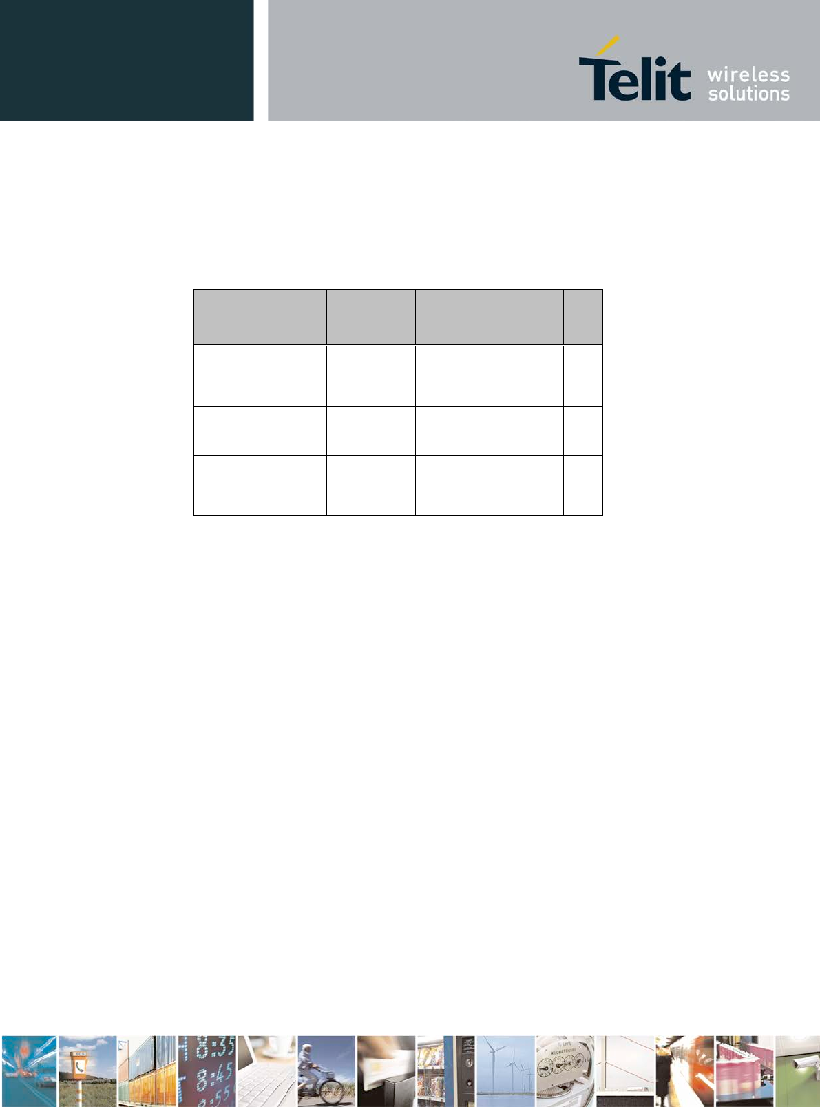
5.4.3 Analog Digital Converter (ADC)
5.4.3.1 Input Voltage Range
It is very important to configure the ADC, so the input voltage range and the ADC voltage
range are matching.
• If the input voltage range is lower than the ADC voltage range, the resolution will not
be fully utilized.
• If the input voltage range is higher than the ADC voltage range, all values above the
maximum ADC voltage range will be limited to the maximum value, also called the
saturation point.
Input voltage range and saturation point depend on the configured ADC reference voltage
(see 5.4.4) and the chosen prescaling.
Input Voltage Range = ADC Reference Voltage / Prescaler
Limitation for maximum input voltage is described in 5.4.5
5.4.4 ADC Reference Voltage
ADC Reference voltage can be obtained from:
• Internal band gap reference: 1,2V ± 1,5%
or
• External reference pin AREF: min. 0,83V typ. 1,2V max. 1,3V
Source Impedance: <5kΩ
BlueMod+S42 Hardware User Guide
1VV0301303 Rev.3 – 2016-08-22
Reproduction forbidden without written authorization from Telit Communications S.p.A. - All Rights Reserved.
Page 41 of 62
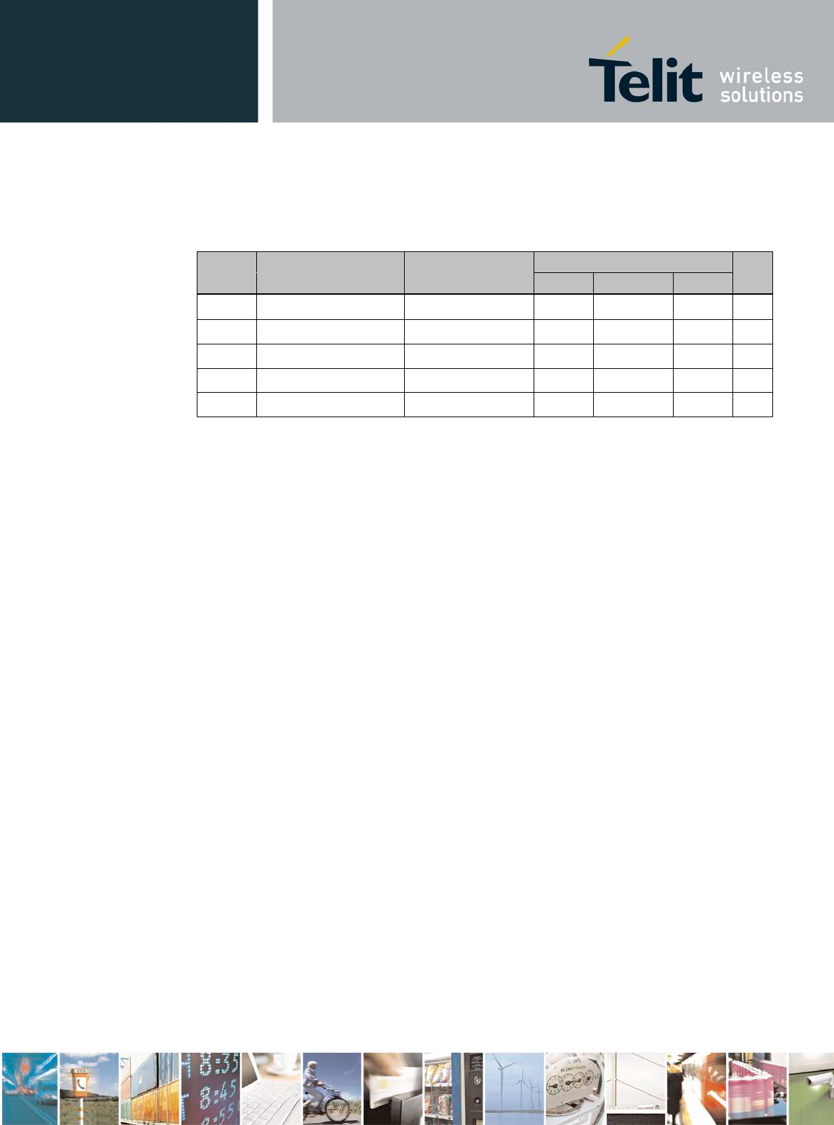
5.4.5 Analog ADC Input AIN
When the ADC is not sampling the AIN input pin has very high impedance and can be
regarded as open circuit.
Table 14 shows the internal impedance for AIN during
sampling for different prescaler settings.
This impedance has to be taken into account when using additional external voltage dividers.
Prescaler Impedance RAIN Unit
min. typ. Max.
1 / 1 120 130 140 kΩ
2 / 3 180 195 210 kΩ
1 / 3 365 390 415 kΩ
Table 14: Input Impedance for AIN
Maximum allowed input voltage at AIN:
(Both of the following rules have to be fulfilled)
• The ADC may not be exposed to voltages >2,4V after the AIN prescaler
and
• The AIN pin must not be exposed to voltages >VDD + 0,3V
BlueMod+S42 Hardware User Guide
1VV0301303 Rev.3 – 2016-08-22
Reproduction forbidden without written authorization from Telit Communications S.p.A. - All Rights Reserved.
Page 42 of 62
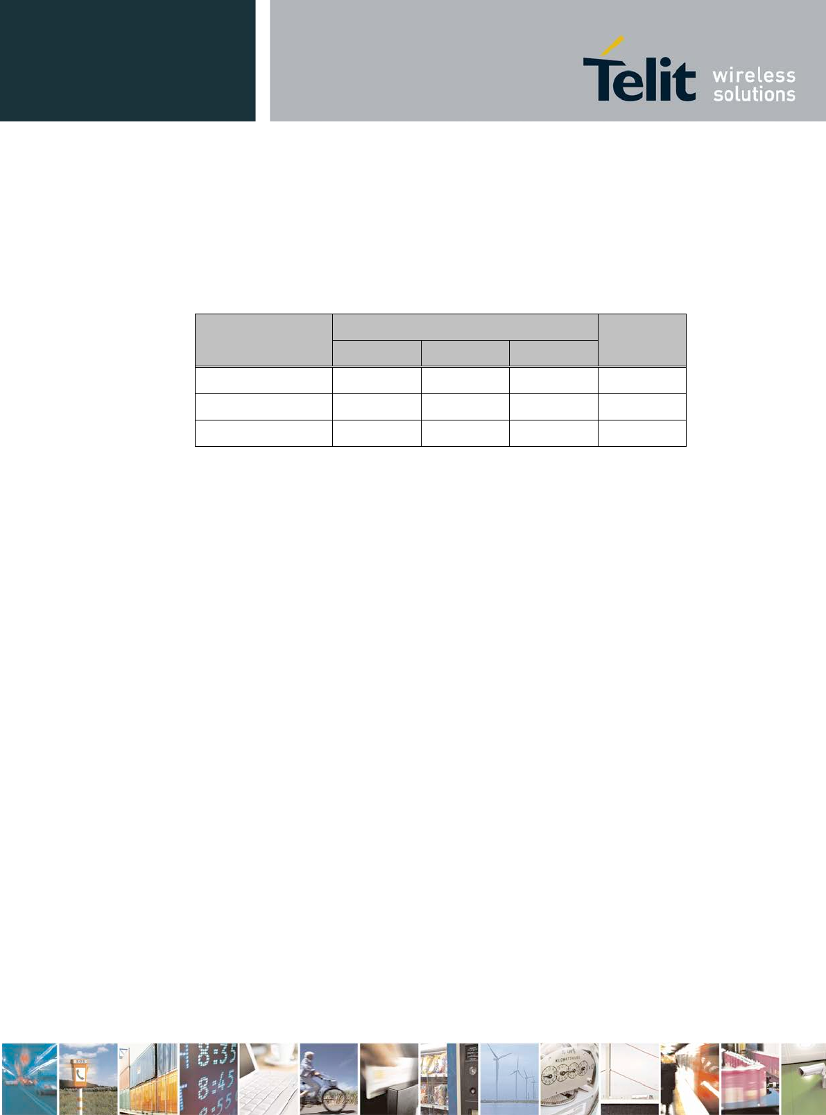
5.5 Power Consumption and Power-Down Modes
5.5.1 Terminal I/O Configuration
The following values are typical power consumption values in the different states.
VSUP = 3,0V, Tamb = 25°C, all GPIOs open, UART inputs at VSUP or GND, SLCK: 32,768 kHz
Condition
Radio inactive Note Slow
clock
SLCK
Current Consumption
Unit
I
Avg
Advertising Off, UICP
not active or serial
interface up
internal
Crystal
1,2
1,2 mA
Advertising Off, UICP
active, serial interface
down (1) internal
Crystal
9
7 µA
Device in reset (2) any 0,44 mA
System off (1,2) 1,2 µA
(1) UART-RXD, IUR-IN# and UART-CTS# signals connected to CMOS
high level
(2) same current consumption w. internal or external slow clock
Table 15: Supply Current Sleep Modes, no Radio Activity
BlueMod+S42 Hardware User Guide
1VV0301303 Rev.3 – 2016-08-22
Reproduction forbidden without written authorization from Telit Communications S.p.A. - All Rights Reserved.
Page 43 of 62
The following table shows the average power consumption of BlueMod+S42operating in the
peripheral device role.
VSUP = 3,0V, Tamb = 25°C, all GPIO lines left open, SLCK: 32,768 kHz
Condition
Radio active Note Slow clock
SLCK Current Consumption
Unit
Tx power (dBm) (8)
max (+4) min (-20)
I
Avg
I
Avg
Standby, Advertising on 3 channels,
advertising interval: 1,28s,UICP not active
or serial interface up (5) internal (7
ext. Crystal
1,2
1,2
1,2
1,2 mA
Standby, Advertising on 3 channels,
advertising interval: 1,28s,UICP active
and serial interface down (1) internal (7)
ext. Crystal
17,6
16,0
14,5
12,9 µA
Connected, connection interval:
1,28s,UICP not active or serial interface
up, no data traffic (5) internal (7)
ext. Crystal
1,2
1,2
1,2
1,2 mA
Connected, connection interval:
1,28s,UICP active and serial interface
down (1) internal (7)
ext. Crystal
10,4
8,7 10,1
8,4 µA
Connected, connection interval: 7,5 ms,
no data traffic (2,3,6) 1,6 1,5 mA
Connected, connection interval: 7,5 ms,
data traffic 115 kbit/s at the serial port,
central to peripheral (2,6,9) tbd tbd mA
Connected, connection interval: 7,5 ms,
data traffic 115 kbit/s at the serial port,
peripheral to central (2,6,9) tbd tbd mA
Connected, connection interval: 40 ms,
no data traffic (2,4,6) 1,3 1,3 mA
Connected, connection interval: 37,5ms,
data traffic 115 kbit/s at the serial port,
peripheral to central
(2,4,6,
9) tbd tbd mA
Notes
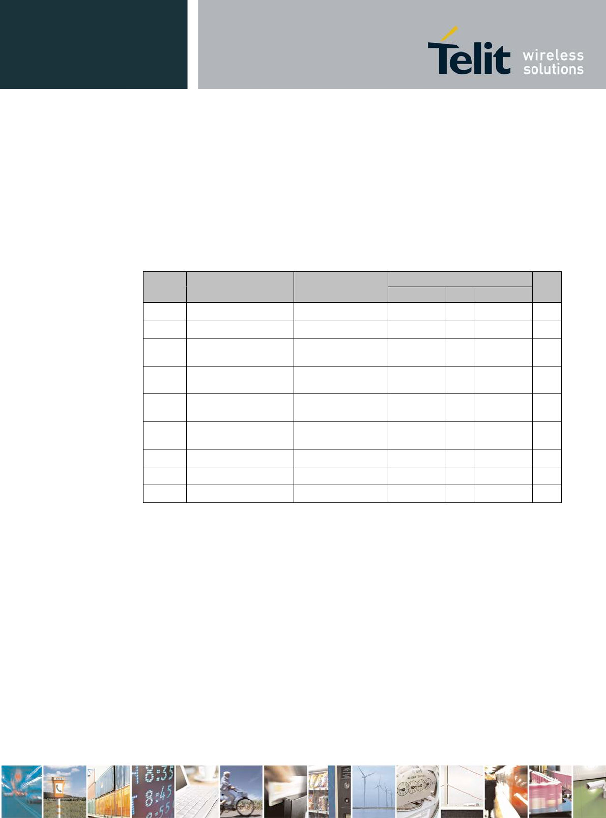
(1) UART-CTS#, IUR-IN#, UART-RXD driven to CMOS high level, all UART output lines left open
(2) connection parameters are setup by the central device when connection is established
(3) no data to be transmitted, central device sends an empty packet (80 bit) peripheral device answers (empty packet: 80 bit)
(4) these are a typical connection parameters used by an iPhone, iPad or iPad mini device in the central device role
(5) UART-inputs connected to GND or VSUP; UART output lines left open
(6) same current consumption w. internal or external slow clock
(7) RC oscillator internal to nRF52832, periodically trimmed by S-device
(8) TX power as set by AT command
(9)
Effective Data throughput lower due to flow control in older FW versions lower current consumption BlueMod+S
Table 16: Supply Current BLE Terminal I/O Profile, Peripheral Device Role
BlueMod+S42 Hardware User Guide
1VV0301303 Rev.3 – 2016-08-22
Reproduction forbidden without written authorization from Telit Communications S.p.A. - All Rights Reserved.
Page 44 of 62
5.6 RF Performance
5.6.1 BLE Receiver
VSUP = 1,7V to 3,6V, Tamb = +20°C
Measured conducted according to BT specification RF-PHY.TS/4.0.1
Receiver Frequency
[GHz] Min Typ Max BT
Spec Unit
Sensitivity at 30,8% PER
2,402 -92,5 -70
≤ -70 dBm
2,440 -93,0 -70
2,480 -93,5 -70
Reported PER during PER
report integrity test 2,426 50 50 65,4 50
< PER
< 65,4 %
Maximum received signal at 30,8% PER -10 0 ≥ -10 dBm
Continuous power required to
block Bluetooth reception at
-67dBm with 0,1% BER
0,030 – 2,000 -30 -30
dBm
2,000 – 2,400 -35 -35
2,500 – 3,000 -35 -35
3,000 – 12,75 -30 -30
C/I co-channel 10 21 ≤21 dB
Adjacent channel
Selectivity C/I
F = F0 + 1 MHz 1 15 ≤15 dB
F = F0 - 1 MHz 1 15 ≤15 dB
F = F0 + 2 MHz -25 -17 ≤-17 dB
F = F0 - 2 MHz -25 -15 ≤-15 dB
F = F0 + 3 MHz -51 -27 ≤-27 dB
F = F0 - 5 MHz -51 -27 ≤-27 dB
F = Fimage -30 -9 ≤-9 dB
Maximum level of intermodulation interferers -50 -36 ≥-50 dBm
VSUP = 1,7V to 3,6V, Tamb = -40°C
Measured conducted according to BT specification RF-PHY.TS/4.0.1
Receiver Frequency
[GHz] Min Typ Max BT
Spec Unit
Sensitivity at 30,8% PER
2,402 -93,0 -70
≤ - 70 dBm
2,440 -93,5 -70
2,480 -94,0 -70
VSUP = 1,7V to 3,6V, Tamb = +85°C
Measured conducted according to BT specification RF-PHY.TS/4.0.1
Receiver Frequency
[GHz] Min Typ Max BT
Spec Unit
Sensitivity at 30,8% PER
2,402 -93,0 -70
≤ . 70 dBm
2,440 -93,5 -70
2,480 -94,0 -70
Table 17: RF Performance BLE Receiver
BlueMod+S42 Hardware User Guide
1VV0301303 Rev.3 – 2016-08-22
Reproduction forbidden without written authorization from Telit Communications S.p.A. - All Rights Reserved.
Page 45 of 62
5.6.2 BLE Transmitter
VSUP = 1,7V to 3,6V, Tamb = +20°C
Measured conducted according to BT specification RF-PHY.TS/4.0.1
Transmitter
Frequency
[GHz]
Min
Typ
Max
BT
Spec
Unit
RF Transmit Power
2,402 4,9 -20 to
+10 dBm 2,440 5,1
2,480 5,0
Programmable RF Transmit
Power Range
(at+RFMAXTXPWR) 2,402 – 2,480 -20 +4 N/A dBm
RF Transmit Power Whisper 2,402 – 2,480 -40 N/A dBm
ACP
F = F0 ± 2MHz -48 ≤ -30
dBm F = F0 ± 3MHz -55 ≤ -30
F = F0 ± > 3MHz <-60 ≤ -30
∆f1avg maximum modulation 225 255 275 225
< f1avg
< 275 kHz
∆f2max minimum modulation (test threshold 185
kHz) 99,9 100 ≥ 99,9 %
∆f2avg / ∆f1avg 0,8 1,0 ≥ 0,8
Frequency Offset -150 ±20 +150 ± 150 kHz
Carrier drift rate 5 20 ≤ 20 kHz/
50µs
Carrier drift 5 50 ≤ 50 kHz
VSUP = 1,7V to 3,6V, Tamb = -40°C
Measured conducted according to BT specification RF-PHY.TS/4.0.1
Transmitter Frequency
[GHz] Min Typ Max BT
Spec Unit
RF transmit Power
2,402 6,2 -20 to
+10 dBm 2,440 6,0
2,480 6,2
ACP
F = F0 ± 2MHz -45 ≤ -30
dBm F = F0 ± 3MHz -50 ≤ -30
F = F0 ± > 3MHz <-60 ≤ -30
Frequency Offset -150 ±35 +150 ± 150 kHz
Carrier drift rate 10 20 ≤ 20 kHz/
50µs
Carrier drift 20 50 ≤ 50 kHz
VSUP = 1,7V to 3,6V, Tamb = +85°C
Measured conducted according to BT specification RF-PHY.TS/4.0.1
Transmitter Frequency
[GHz] Min Typ Max BT
Spec Unit
RF transmit Power 2,402 4,0 -20 to
+10 dBm
2,440 4,0

BlueMod+S42 Hardware User Guide
1VV0301303 Rev.3 – 2016-08-22
Reproduction forbidden without written authorization from Telit Communications S.p.A. - All Rights Reserved.
Page 46 of 62
2,480 4,0
ACP
F = F0 ± 2MHz -45 -20 ≤ -30
dBm F = F0 ± 3MHz -50 -40 ≤ -30
F = F0 ± > 3MHz <-55 -30 ≤ -30
Frequency Offset -150 ±35 +150 ± 150 kHz
Carrier drift rate 10 20 ≤ 20 kHz/
50µs
Carrier drift 20 50 ≤ 50 kHz
Table 18: RF Performance BLE Transmitter
5.6.3 Antenna-Gain and Radiation Pattern
If BlueMod+S42/AI is integrated into an end product while the recommendations depicted in
6.4 Placement Recommendation are maintained, the following typical antenna radiation
patterns can be expected.
Radiation Pattern will depend on the end products PCB size, masses in the antenna
environment, housing material and geometrics. Typical antenna gain is about +2dBi.
Antenna patterns will be updated in final document
.
Figure 13: Typical Antenna Radiation Pattern at 2402MHz
.
Figure 14: Typical Antenna Radiation Pattern at 2441MHz
Figure 15: Typical Antenna Radiation Pattern at 2480MHz

BlueMod+S42 Hardware User Guide
1VV0301303 Rev.3 – 2016-08-22
Reproduction forbidden without written authorization from Telit Communications S.p.A. - All Rights Reserved.
Page 47 of 62
5.7 Power-Up Time
The time until the BlueMod+S42is able to accept link requests or serial data depends on the
firmware version and on the source for the slow clock. Using TIO firmware version , the
device is ready (as indicated by GPIO IOA, measured from the release of EXT_RES# or
VSUP rising above 1,7V) as follows:
• tDeviceReady 0,9s (typ.) if an external 32,768kHz crystal is connected.
• tDeviceReady 1,7s (typ.) if no external signal is provided so the internal RC is used.
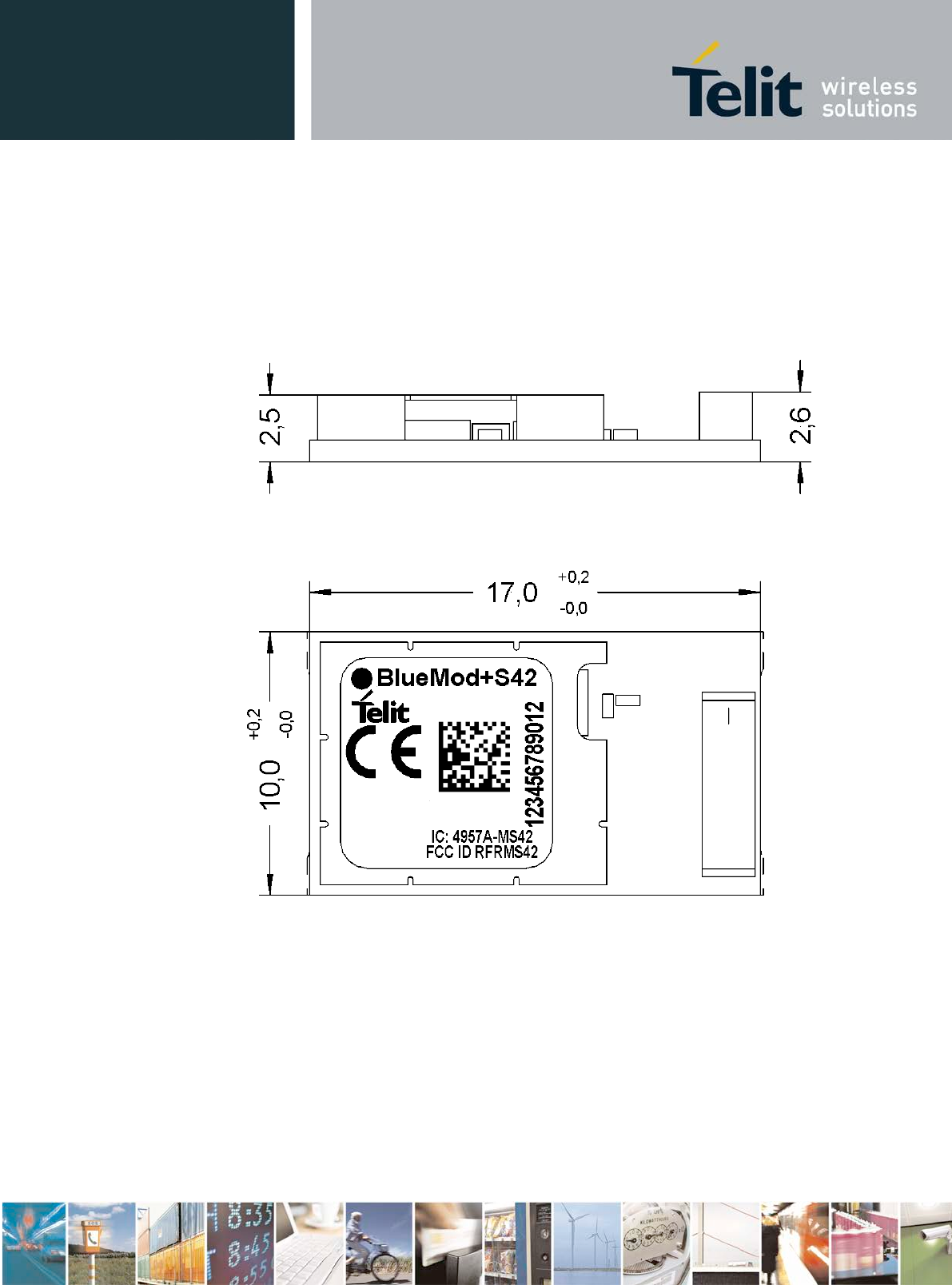
BlueMod+S42 Hardware User Guide
1VV0301303 Rev.3 – 2016-08-22
Reproduction forbidden without written authorization from Telit Communications S.p.A. - All Rights Reserved.
Page 49 of 62
6.2 Recommended Land Pattern
F1
E1
D1
C1
B1
A1 A2 A3 A4 A5 A6 A7 A8
F2
E2
D2
C2
B2
F3
E3
D3
C3
B3
F4
E4
D4
C4
B4
F5
E5
D5
C5
B5
F6
E6
D6
C6
B6
F7
E7
D7
C7
B7
F8
E8
D8
C8
B8
1,25
1,25
7x1,5=10,5
5x1,5=7,5
0,9
17,0
10,0
Figure 17: BlueMod+S42 Land Pattern TOP VIEW
Note: All dimensions are in mm.
6.3 Re-flow Temperature-Time Profile
The data here is given only for guidance on solder and has to be adapted to your process and
other re-flow parameters for example the used solder paste. The paste manufacturer provides
a re-flow profile recommendation for his product.
Figure 18: Soldering Temperature-Time Profile (For Reflow Soldering)
BlueMod+S42 Hardware User Guide
1VV0301303 Rev.3 – 2016-08-22
Reproduction forbidden without written authorization from Telit Communications S.p.A. - All Rights Reserved.
Page 50 of 62
Preheat Main Heat Peak
tsmax tLmax tpmax
Temperature Time Temperature Time Temperature Time
[°C] [sec] [°C] [sec] [°C] [sec]
150
100
217 90 260
10
230 50
Average ramp-up rate [°C / sec] 3
Average ramp-down rate [°C / sec] 6
Max. Time 25°C to Peak
Temperature [min.] 8
Opposite side re-flow is prohibited due to module weight.
Devices will withstand the specified profile and will withstand up to 1 re-flows to a maximum
temperature of 260°C. The reflow soldering profile may only be applied if the
BlueMod+S42resides on the PCB side looking up. Heat above the solder eutectic point while
the BlueMod+S42is mounted facing down may damage the module permanently.
6.4 Placement Recommendation
To achieve best radio performance for BlueMod+S42/AI, it is recommended to use the
placement shown in Figure 19. This is a “corner placement”
meaning the BlueMod+S42/AI is placed such that the antenna comes close to the corner of
the application PCB (red area). So, the yellow area is outside the PCB and regards to the
housing, too (refer to 6.5).
Please note that for best possible performance the antenna should be directed away from the
application PCB as shown in Figure 19.
max.0,5 4,5
10
10
max.0,5
10
15
no bare copper (exept solder pads for module)
no copper and components on any layer
no components on any layer
provide solid ground plane(s) as large as possible around
17
do not place any conductive parts in this area
20
20
40
area
Applic. PCB

BlueMod+S42 Hardware User Guide
1VV0301303 Rev.3 – 2016-08-22
Reproduction forbidden without written authorization from Telit Communications S.p.A. - All Rights Reserved.
Page 51 of 62
Figure 19 : BlueMod+S42/AI Placement Recommendation
6.5 Housing Guidelines
The individual case must be checked to decide whether a specific housing is suitable for the
use of the internal antenna. A plastic housing must at least fulfill the following requirements:
Non-conductive material, non-RF-blocking plastics
No metallic coating
ABS is suggested
6.6 Antenna Issues
BlueMod+S42/AI comprises a ceramic antenna which as a component is soldered to the
circuit board. This solution is functional for a BlueMod+S42/AI integrated into a plastic
housing.
The performance of the antenna has to be checked within the final integration environment.
Adjacent PCBs, components, cables, housings etc. could otherwise influence the radiation
pattern or be influenced by the radio wave energy. It must be ensured that the antenna is not
co-located or operating in conjunction with any other antennas, transmitters, cables or
connectors.
6.7 Safety Guidelines
According to SAR regulation EN 62479:2010 the BlueMod+S42is not intended to be used in
close proximity to the human body. Please refer to above-mentioned regulation for more
specific information.
In respect to the safety regulation EN60950-1: 2006 + A11: 2009 + A1: 2010 + AC: 2011 all
conductive parts of the BlueMod+S42are to be classified as SELV circuitry. OEM’s
implementing the BlueMod+S42in their products should follow the isolation rules given in
regulation EN 60950-1: 2006.
The PCB material of the BlueMod+S42 is classified UL-94V0.
6.8 Cleaning
In general, cleaning the modules mounted on the host board is strongly discouraged. Residues
between module and host board cannot be easily removed with any cleaning method..
• Cleaning with water or any organic solvent can lead to capillary effects where the
cleaning solvent is absorbed into the gap between the module and the host board. The
combination of soldering flux residues and encapsulated solvent could lead to short
circuits between conductive parts. The solvent could also damage any labels.
• Ultrasonic cleaning could damage the module permanently. Especially for crystal
oscillators the risk of damaging is very high.

BlueMod+S42 Hardware User Guide
1VV0301303 Rev.3 – 2016-08-22
Reproduction forbidden without written authorization from Telit Communications S.p.A. - All Rights Reserved.
Page 52 of 62
7 Application Diagram
The following schematic shows a typical application of BlueMod+S42. The module is
connected to some MCU running the application layer. MCU and BlueMod+S42use the same
3,3V power supply. The serial interface has RTS/CTS flow control and UICP support in this
example. The optional hangup feature to close down the link is provided. As an option to save
power an external slow clock crystal may be used. The 32,768kHz crystal can be placed on
customers HW or may be optionally on module. Contact Telit sales. All other module pins
may be left unconnected.
Host MCU
VDD
GND
+3V3
GPIO (o)
In this example BlueMod+S is connected to an MCU supporting UICP, RTS/CTS flow control and Hangup.
The slow clock oscillator (32,768kHz ) is optional; it helps to save power during power down states.
470R
BlueMod+S42/AI
E-6,F-6 VSUP
B-1 EXT-RES#
UART-RXD
UART-TXD
UART-CTS#
UART-RTS#
GPIO[4]/Hangup
TXD (o)
RXD (i)
RTS# (o)
CTS# (i)
GPIO (o)
XL-IN/SLCK
32,768kHz CRYSTAL
The crystal is optional. Leave A-6 open
if the crystal is not present.
B-4
D-4
A-6
all GND pads (14) must be connected.
Blocking capacitors not shown.
pushpull or OD
pushpull
A-5 XL-OUT
D-2
F-4
F-3
D-7
IUR-IN#
D-5
IUR-OUT#
GPIO/DTR# (o)
GPIO/DSR# (i)
Figure 20: Typical Application Schematics

BlueMod+S42 Hardware User Guide
1VV0301303 Rev.3 – 2016-08-22
Reproduction forbidden without written authorization from Telit Communications S.p.A. - All Rights Reserved.
Page 53 of 62
8 Compliances
The BlueMod+S42/AI has been tested to comply to the appropriate EU, FCC, IC and KCC
directives.
CE testing is intended for end products only. Therefore CE testing is not mandatory for a
Bluetooth Module sold to OEM’s. However Telit E+V GmbH provides CE tested Modules
for customers in order to ease CE compliance assessment of end products and to minimize
test effort.
8.1 Declaration of Conformity CE
The BlueMod+S42/AI fully complies with the essential requirements of the following EU
directives:
• R&TTE 1999/5/EC
• RoHS 2011/65/EC
The actual version of EU Declaration of Conformity (EU DoC) can be downloaded from the
Telit download zone.
The CE compliance declaration is in progress.
The above link may expire, because a new version of the EU DoC is available. Please look up
the EU DoC from the Telit web site directly then.
8.2 FCC Compliance
The BlueMod+S42/AI has been tested to fulfill the FCC requirements. Test reports are
available on request. Grants of the Full Modular Approval is shown below.
The FCC Certification is in progress: FCC ID will be RFRMS42
8.2.1 FCC Grant
8.2.2 FCC Statement
This device complies with 47 CFR Part 2 and Part 15 of the FCC Rules and with.
Operation is subject to the following two conditions:
this device my not cause harmful interference, and
BlueMod+S42 Hardware User Guide
1VV0301303 Rev.3 – 2016-08-22
Reproduction forbidden without written authorization from Telit Communications S.p.A. - All Rights Reserved.
Page 54 of 62
this device must accept any interference received, including interference that may cause
undesired operation.
8.2.3 FCC Caution
WARNING:
Changes or modifications made to this equipment not expressly approved by Telit may void
the FCC authorization to operate this equipment.
8.2.4 FCC Warning
This equipment has been tested and found to comply with the limits for a Class B digital
device, pursuant to Part 15 of the FCC Rules. These limits are designed to provide reasonable
protection against harmful interference in a residential installation. This equipment generates,
uses and can radiate radio frequency energy and, if not installed and used in accordance with
the instructions, may cause harmful interference to radio communications. However, there is
no guarantee that interference will not occur in a particular installation. If this equipment does
cause harmful interference to radio or television reception, which can be determined by
turning the equipment off and on, the user is encouraged to try to correct the interference by
one or more of the following measures:
Reorient or relocate the receiving antenna.
Increase the separation between the equipment and receiver.
Connect the equipment into an outlet on a circuit different from that to which the receiver is
connected.
Consult the dealer or an experienced radio/TV technician for help.
8.2.5 FCC RF-exposure Statement
The BlueMod+S42/AI complies with the FCC/IC RF radiation exposure limits set forth for an
uncontrolled environment.
The output power is < 10mW EIRP and therefore according to “FCC KDB 447498 D01
General RF Exposure Guidance v05” Appendix A, table “SAR Exclusion Threshold”,
excluded from SAR testing for test separation distances ≥ 5mm and if it is not used in co-
locations with other antennas. If the product implementing the BlueMod+S42/AI has other
antennas in co-location or separation distances < 5mm an FCC TCB should be asked for a
Class II Permissive Change.

BlueMod+S42 Hardware User Guide
1VV0301303 Rev.3 – 2016-08-22
Reproduction forbidden without written authorization from Telit Communications S.p.A. - All Rights Reserved.
Page 55 of 62
8.2.6 FCC Labeling Requirements for the End Product
Any End Product integrating the BlueMod+S42/AI must be labeled with at least the following
information:
This device contains transmitter with
FCC ID: RFRMS42
IC: 4957A-MS42
8.3 IC Compliance
The BlueMod+S42/AI will been tested to fulfill the IC requirements. Test reports RSS-210 of
Industry Canada are available on request. Grant of the Full Modular Approval is shown
below.
The IC Certification is in progress: FCC ID will be 4957A-MS42
8.3.1 IC Grant
8.3.2 IC Statement
(11) Ce dispositif doit être installé et exploité dans une enceinte entièrement fermée afin de
prévenir les rayonnements RF qui pourraient autrement perturber la navigation
aéronautique. L’installation doit être effectuée par des installateurs qualifiés, en pleine
conformité avec les instructions du fabricant.
(ii) Ce dispositif ne peut être exploité qu’en régime de non-brouillage et de non-protection,
c’est-à-dire que l’utilisateur doit accepter que des radars de haute puissance de la même bande
de fréquences puissent brouiller ce dispositif ou même l’endommager. D’autre part, les
capteurs de niveau à propos desquels il est démontré qu’ils perturbent une exploitation
autorisée par licence de fonctionnement principal doivent être enlevés aux frais de leur
utilisateur.
This device complies with Industry Canada license-exempt RSS standard(s).
Operation is subject to the following two conditions:
(1) this device may not cause interference, and
(2) this device must accept any interference, including interference that may cause undesired
operation of the device.
NOTICE:
This Class B digital apparatus complies with Canadian ICES-003.
Cet appareil numérique de la classe B est conforme à la norme NMB-003 du Canada.

BlueMod+S42 Hardware User Guide
1VV0301303 Rev.3 – 2016-08-22
Reproduction forbidden without written authorization from Telit Communications S.p.A. - All Rights Reserved.
Page 56 of 62
8.3.3 IC Caution
WARNING:
Changes or modifications made to this equipment not expressly approved by Telit may void
the IC authorization to operate this equipment.
8.3.4 IC RF-exposure Statement
This equipment is portable device. According to RSS-102 Issue 5 §2.5.1 Exemption Limits
for Routine Evaluation – SAR Evaluation Table 1, the allowed distances to the human body
for products implementing the BlueMod+S42 can be calculated as follows. If the intended use
of the end product asks for smaller distances a SAR evaluation has to be made with the end
product.
• Max. RF output power: Occurs at -40°C at 2402MHz to 2480MHz with +6dBm
• Antenna peak Gain is +2dBi
• Resulting max. RF output power is +8dBm = 6,3mW < 7mW
• Table 1 shows that for 2450MHz the distance at 7mW should be ≥ 10mm
8.3.5 IC Labeling Requirements for the End Product
Any end product integrating the BlueMod+S42/AI must be labeled with at least the following
information:
This device contains transmitter with
FCC ID: RFRMS42
IC-ID: 4957A-MS42
8.3.6 IC Label Information BlueMod+S42
The BlueMod+S42 shows IC-ID on the product label,
Model: BlueMod+S42
The IC-ID is: IC. 4957A-MS42

BlueMod+S42 Hardware User Guide
1VV0301303 Rev.3 – 2016-08-22
Reproduction forbidden without written authorization from Telit Communications S.p.A. - All Rights Reserved.
Page 57 of 62
8.4 KCC Certification
The BlueMod+S42/AI will be certified in Korea under the Clause 2, Article 58-2 of Radio
Waves Act.
KCC Certification is in progress
8.4.1 KCC Certificate
8.5 Bluetooth Qualification
The BlueMod+S42 will be a qualified design according to the Bluetooth Qualification
Program Reference Document (PRD) V2.3.
The BTSIG qualification is in progress
The Declaration ID is:
The Qualified Design ID is:
tbd
For further information about marking requirements of your product attention should be paid
the Bluetooth Brand Usage Guide at
https://www.bluetooth.org/en-us/bluetooth-brand/bluetooth-brand
According to the Bluetooth SIG rules (Bluetooth Declaration Process Document – DPD) you
must complete a Product Listing and Declaration of Compliance (DoC) referencing the
Qualified Design (QDID) for your product. For further information see www.Bluetooth.org or
contact Telit.
8.6 RoHS Declaration
RoHS evaluation is in progress
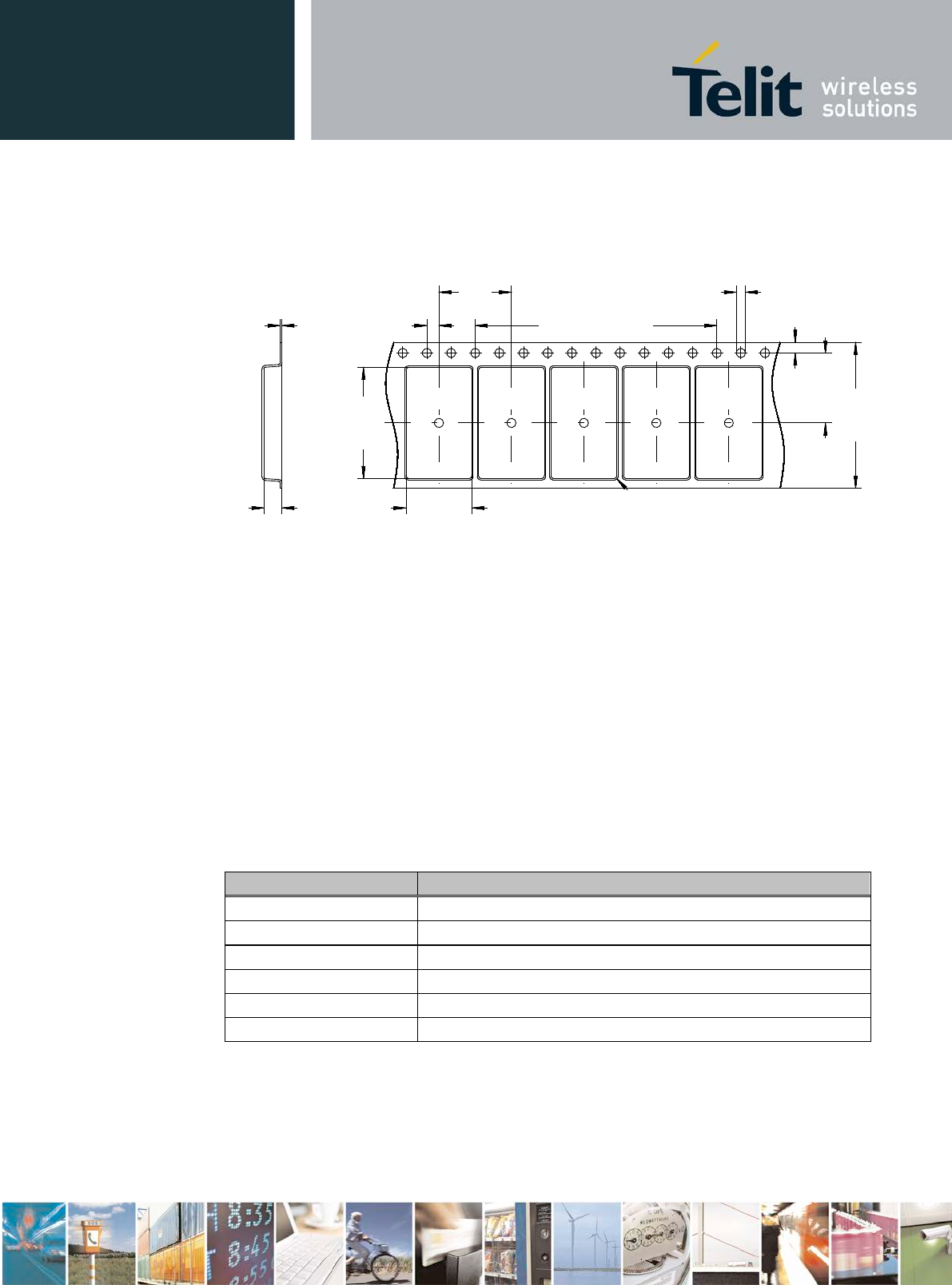
BlueMod+S42 Hardware User Guide
1VV0301303 Rev.3 – 2016-08-22
Reproduction forbidden without written authorization from Telit Communications S.p.A. - All Rights Reserved.
Page 59 of 62
9.1 Tape
The dimensions of the tape are shown in the drawing below (values in mm):
2,0
+0,1
-0,1
10,9
+0,1
-0,1
18,3
+0,1
-0,1
R 0,5
1,75
+0,10
-0,10
24,0
+0,3
-0,3
10x4,0=40,0
+0,2
-0,2
1,5
+0,1
-0,0
12,0
11,5
+0,1
-0,1
0,3
3,0
9.2 Reel
tbd
9.3 Package Label
Package box, dry shield bag and reel are each marked with the following label:
Field Description
name Name of product
p/n Product number
firmware Firmware version
fw p/n Product number of firmware
trace [Manufacturer m (optional)]Date (CalendarWeekYear) wwyy
quantity Number of contained modules
If the label on the package box is different to the label described please contact Telit for
detailed information.

BlueMod+S42 Hardware User Guide
1VV0301303 Rev.3 – 2016-08-22
Reproduction forbidden without written authorization from Telit Communications S.p.A. - All Rights Reserved.
Page 60 of 62
10 Ordering Information
10.1 Part Numbers
BlueMod+S42 is available in the following variants:
Name Antenna Firmware
Version Order No. MOQ /
units Comments
BlueMod+S42/AI/Central Internal 53346-xx tbd
BlueEva+S42/Central Internal 2.xxx 53352-xx 1 Evaluation Kit
Other variants on request, please contact Telit sales department.
10.2 Standard Packing Unit
The standard packing units are 1000 pieces on Tape and Reel
10.3 Evaluation Kit
The kit BlueEva+S42 is available to evaluate functionality and start your firmware
implementation.

BlueMod+S42 Hardware User Guide
1VV0301303 Rev.3 – 2016-08-22
Reproduction forbidden without written authorization from Telit Communications S.p.A. - All Rights Reserved.
Page 61 of 62
11 Safety Recommendations
READ CAREFULLY
Be sure the use of this product is allowed in the country and in the environment required. The
use of this product may be dangerous and has to be avoided in the following areas:
Where it can interfere with other electronic devices in environments such as hospitals,
airports, aircrafts, etc.
Where there is risk of explosion such as gasoline stations, oil refineries, etc. It is
responsibility of the user to enforce the country regulation and the specific environment
regulation.
Do not disassemble the product; any mark of tampering will compromise the warranty
validity. We recommend following the instructions of the hardware user guides for a correct
wiring of the product. The product has to be supplied with a stabilized voltage source and the
wiring has to be conforming to the security and fire prevention regulations. The product has to
be handled with care, avoiding any contact with the pins because electrostatic discharges may
damage the product itself.
The system integrator is responsible of the functioning of the final product; therefore, care has
to be taken to the external components of the module, as well as of any project or installation
issue, because the risk of disturbing external devices or having impact on the security. Should
there be any doubt, please refer to the technical documentation and the regulations in force.
Every module has to be equipped with a proper antenna with specific characteristics. The
antenna has to be installed with care in order to avoid any interference with other electronic
devices and has to guarantee a minimum distance from the body (20 cm). In case of this
requirement cannot be satisfied, the system integrator has to assess the final product against
the SAR regulation.
The European Community provides some Directives for the electronic equipments
introduced on the market. All the relevant information’s are available on the European
Community website:
http://ec.europa.eu/enterprise/sectors/rtte/documents/
The text of the Directive 99/05 regarding telecommunication equipments is available,
while the applicable Directives (Low Voltage and EMC) are available at:
http://ec.europa.eu/enterprise/sectors/electrical/
BlueMod+S42 Hardware User Guide
1VV0301303 Rev.3 – 2016-08-22
Reproduction forbidden without written authorization from Telit Communications S.p.A. - All Rights Reserved.
Page 62 of 62
12 Document History
Revision
Date
Changes
0
2016-07-16
First preliminary issue
1
2016-08-12
Fixed wrong chapter numbers
Add picture to chapter 3.8.2 Connection of an External
32,768 kHz Crystal
Added Tx power and Rx sensivity values at +25 °C
Added some power consumption values
Removed all references to extern SCLK signal
2
2016-08-22
Added associated Telit ref numbers in related documents
list
Chap. 2.1: Corrected value from -30dBm to -20dBm for
power control range and added Whisper Mode with
-40dBm
Chap. 2.4: Added new block diagram with 32MHz crystal
and optional 32,768kHz crystal
Chap. 6.1: Added new label to drawing
Chap. 7: Additionally 32,768kHz signal feeding option
removed, only 32,768 crystal possible with nRF52832
Chap. 8: Formatting header 2 corrected, FCC and IC ID’s
added (multiple times), progress notes added for CE, FCC,
IC, KCC, BTSIG, RoHS
3
Added ITA information