Telkonet PST-2200 Occupancy Sensor User Manual 6 70 118 SS2000 Battery Replacement
Telkonet, Inc. Occupancy Sensor 6 70 118 SS2000 Battery Replacement
Telkonet >
Contents
Users Manual Part 1

For more information, please email us at:
support@telkonet.com.
Telkonet Communications, Inc.
20374 Seneca Meadows Parkway
Germantown, Maryland 20876
Telephone: 877-282-2519
www.telkonet.com
Copyright © 2009 Telkonet Inc. All rights Reserved.
Document Number: 6.70.119 r4
Warning: Read all instructions
carefully before installing this
product.
Battery Replacement
Procedures
for
Telkonet SS2200-Series
Occupancy Sensors
SS2200 Occupancy Sensor
for
Telkonet Energy Management
Systems
Specifications:
•Maximum Diameter (at face) - 13.0mm
•Minimum Diameter (at base) - 11.3mm
•Depth – 4cm
•Weight (batteries loaded) – 1lb 1oz
•Power Source – 4xAA Industrial Alkaline
AA Alkaline batteries are the minimum
permissible battery standard for SS2200
sensors. Non-alkaline “long-life” batteries will not
yield acceptable long-term performance. Where
possible, the use of “Industrial” batteries
(Energizer EN-91-LR6-AM3 [Zn/MnO2] or
equivalent) is recommended.
Batteries should be replaced as part of
scheduled servicing as follows:
• Standard Alkaline Batteries – Approximately
every 24 months
• Industrial / "Heavy Duty"Batteries –
Approximately every 18 months
Operational Notes:
Following Sensor battery replacement, it is not necessary
to perform the re-association process. The SS5000 /
SS5200 Thermostat or SS1107 Controller will have
already stored the Sensor’s unique ID.
• For installation and support information, see
Technical Note 6.30.115.
• For information regarding associating SS2200-
Series sensors see Technical Note 6.70.104
This equipment has been tested and found to
comply with the limits for a class B digital
device, pursuant to part 15 of the FCC Rules.
These limits are designed to provide reasonable
protection against harmful interference in a
residential installation. This equipment
generates, uses and can radiate radio frequency
energy and if not installed and used in
accordance with the instructions, may cause
harmful interference to radio communications.
However, there is no guarantee that interference
will not occur in a particular installation. If this
equipment does cause harmful interference to
radio or television reception, which can be
determined by turning the equipment off and on,
the user is encouraged to try to correct the
interference by one or more of the following
measures:
· Reorient or relocate the receiving antenna.
· Increase the separation between the
equipment and receiver.
· Connect the equipment into an outlet on a
circuit different from that to which the receiver
is connected.
· Consult the dealer or an experienced radio/
TV technician for help.
The user is cautioned that changes and
modifications made to the equipment without the
approval of manufacturer could void the user’s
authority to operate this equipment.
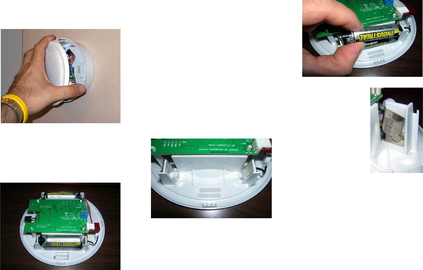
Battery Replacement Procedure
Step 1: Remove the retaining screw, and rotate
the Sensor faceplate until it disengages from the
mounted base.
Step 2: Place the sensor faceplate on a stable,
flat surface. Proceed with a good grip on the
assembly and take care not to disengage the
battery wires.
With the batteries removed, take a moment to
orient yourself with the battery clips and polarity
markings on the unit. Note that:
•The negative terminal clip for each
battery is designed to act as a “spring” to push
the battery’s positive terminal into place.
•There is a small embossed polarity
guide on the inside of the faceplate, just in front
of the battery clips. Note the orientation when
looking at the batteries from the side:
•The bottom battery always has its
positive terminal facing right
•The top battery always has its positive
terminal facing left
•Check to ensure there is no oxidation or
battery “acid” on the battery terminals.
Dispose of used batteries in a safe and approved
manner.
Step 4: Insert the replacement batteries. Begin
by placing the bottom battery, and then the top
for each side. Whenever inserting batteries, it is
best to place the negative battery end on the
negative terminal, and then gently press the
battery into the clip until it seats against the
terminal.
Ensure that there is nothing in between the
battery terminals and the battery clips, such as
stray insulation, paint chips, etc. The battery
terminals must make firm, conducting contact
with the battery clips.
When placing the top
batteries into the clips,
take care not to press
down on the spring
negative clip. Excessive
force will cause the metal
terminal to slide down on
the plastic bracket, and
short against the bottom
terminal. This will short-
circuit the battery,
resulting in possible
damage the Sensor.
Step 5: Visually double-check the assembly
with the new batteries in place. Verify that:
•Battery orientation is correct
•Metal battery clips are not shorted
against each other
•The black power connector is firmly-
attached to the circuit board
•Touch the battery sides with your finger.
If they are warm or hot to the touch, this is a
clear indication of a shorted terminal. Re-
examine the unit.
Step 6: Verify that the retaining screw hole in
the side of the Sensor assembly is oriented near
the matching hole on the mounting plate. Insert
the Sensor assembly into the mounting plate,
and fix in place by rotating the unit slightly
clockwise. Replace the retaining screw.
Step 3: Remove the batteries. The battery clips
are designed to hold the batteries snugly in
place despite a wide variety of mounting options,
so a small, flat-head screwdriver is often of use
in removing the batteries.
Figure 1 - Removing the Sensor from the Mounting Plate
Figure 2 - Sensor Assembly on secure, flat surface
Figure 3 - Battery Orientarion and clips
Figure 4 - Inserting Batteries
Figure 5 - Shorted clips