Telkonet PST6000 Zigbee Temperature Sensor User Manual EcoInsight FCC for Clarkx
Telkonet, Inc. Zigbee Temperature Sensor EcoInsight FCC for Clarkx
UserManual.wiki
>
Telkonet
>
PST6000 User Manual
Owners Manual
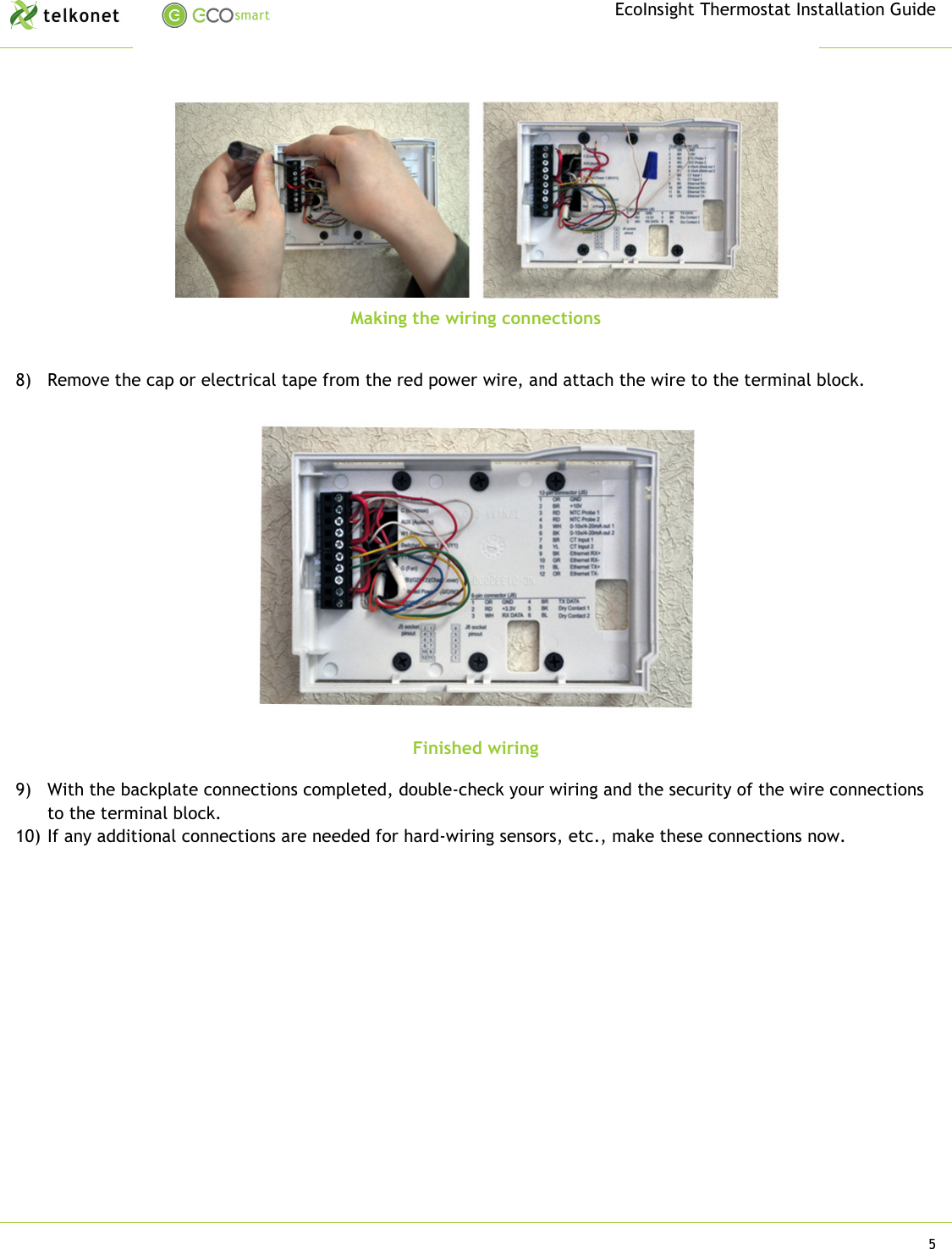
Navigation menu
Upload a User Manual
Namespaces
Wiki Guide
HTML
PDF
Info
Views
User Manual
Discussion / Help
Navigation