Telkonet SS6010 Energy Management Controller User Manual EcoInsight IOM Rev 2 1x
Telkonet, Inc. Energy Management Controller EcoInsight IOM Rev 2 1x
Telkonet >
User Manual

SS6010 EcoInsight+
Installation, Operation & Maintenance Guide
Firmware Version 2.x

EcoInsight+ SS6010
I, O & M Guide
Telkonet, Inc.
For Use with Firmware Version 2.x
20800 Swenson Drive, Suite 175
Contact Telkonet
Waukesha, WI 53186
Revision 2.1
(800) 380-9640
Page i www.telkonet.com
Contact Telkonet .................................................................................................................. 2
EcoSmart Energy Management System......................................................................................... 3
Regulatory Compliance ........................................................................................................ 3
FCC Notice ....................................................................................................................... 3
About This Product ............................................................................................................. 3
ZigBee Wireless ................................................................................................................. 3
Electrical Ratings ................................................................................................................. 4
EcoInsight SS6010 Location Planning ........................................................................................... 5
High Voltage Installation (Non-Class 2) ........................................................................................ 7
Required Equipment ........................................................................................................... 7
Installation ...................................................................................................................... 7
Rating Schedule – Non-Class 2 ............................................................................................... 13
Low Voltage Installation (Class 2) ............................................................................................. 16
Required Equipment .......................................................................................................... 16
Installation ..................................................................................................................... 17
Drywall Mounting Instructions ............................................................................................... 18
JBOX Using Vertical Mud Ring Instructions ................................................................................ 18
Rating Schedule– Class 2: .................................................................................................... 20
Add-Ons ............................................................................................................................ 22
About Wiring ................................................................................................................... 22
NTC Probe ...................................................................................................................... 22
Analog Outputs ................................................................................................................ 23
CT Inputs........................................................................................................................ 23
User Interface .................................................................................................................... 24
Panel Controls ................................................................................................................. 24
The Maintenance Menu ....................................................................................................... 25
Troubleshooting .................................................................................................................. 26
Appendix A: Pinout Tables ...................................................................................................... 30
Appendix B ........................................................................................................................ 35
Appendix C: JBOX Mounting Options .......................................................................................... 37
Appendix D: Types of Radio Modules ......................................................................................... 40
Regular Maintenance ............................................................................................................ 41
Maintenance Menu ............................................................................................................... 42
Advanced Command Menu ...................................................................................................... 43

Contact Telkonet
EcoInsight+ SS6010
I, O & M Guide
Telkonet, Inc.
For Use with Firmware Version 2.x
20800 Swenson Drive, Suite 175
Contact Telkonet
Waukesha, WI 53186
Revision 2.1
(800) 380-9640
Page 2
www.telkonet.com
Contact Telkonet
Company Headquarters: Customer Support:
EcoSmart Sales:
Telkonet, Inc. (800) 380-9640
(888) 703-9398
20800 Swenson Drive Email:
Email
Suite 175 ecosmartsupport@telkonet.com
sales@telkonet.com
Waukesha, WI 53186
P (414) 223-0473
F (414) 258-8307

EcoSmart Energy Management System
EcoInsight+ SS6010
I, O & M Guide
Telkonet, Inc.
For Use with Firmware Version 2.x
20800 Swenson Drive, Suite 175
EcoSmart Energy Management System
Waukesha, WI 53186
Revision 2.1
(800) 380-9640
Page 3 www.telkonet.com
EcoSmart Energy
Management System
The EcoSmart Energy Management System is designed to reduce HVAC
energy consumption without interfering with an occupant’s comfort.
EcoSmart thermostats such as the SS6010 will automatically learn and
adapt to the heating and cooling patterns of each room. For example, a
room on the east side of a building will receive direct sunlight in the
morning and will either need less HVAC heating or more HVAC cooling.
However, as the day progresses, the room will need more HVAC heating
or less HVAC cooling as it moves into the shade. An EcoSmart thermostat
will continually monitor the room, learn its patterns, and adjust its
heating and cooling profiles accordingly.
EcoSmart thermostats also learn and adapt to occupant schedules. When
a room is unoccupied, an EcoSmart thermostat will enter an energy saving
mode, allowing the room to drift away from the desired set point. During
this drift period, the thermostat will operate the HVAC unit less often,
reducing energy costs. When the room becomes occupied again, the
EcoSmart Recovery Time™ technology built into each thermostat will
return the room to the set point without the occupant noticing.
The SS6010 is available in several possible configurations, to address
specific requirements of multiple applications including hotel, classroom,
office, university dormitory, military residence hall, retail, public area,
convention center, and a wide variety of commercial and industrial
spaces.
The form factor of all non-networked models is identical, as are the form
factors of the networked versions. Networking options may be added to
the base units at any time via a simple retrofit module process.
Additional controls generally used during installation, maintenance, and
troubleshooting are available in the on-screen Maintenance menu.
Regulatory Compliance & FCC Notice
Warning: Any changes or modifications made to this product not
expressly authorized by the manufacturer could void the user’s right
to operate this device.
The device complies with part 15 of the FCC Rules as well as Industry
Canada Rules and Regulations license-exempt RSS standard(s). Operation
is subject to the following two conditions: (1) This device may not cause
harmful interference, and (2) this device must accept any interference
received, including interference that may cause undesired operation.
Le présent appareil est conforme aux CNR d'Industrie Canada applicables
aux appareils radio exempts de licence. L'exploitation est autorisée aux
deux conditions suivantes : (1) l'appareil ne doit pas produire de
brouillage, et (2) l'utilisateur de l'appareil doit accepter tout brouillage
radioélectrique subi, même si le brouillage est susceptible d'en
compromettre le fonctionnement.
A separation distance of at least 20 centimeters should be maintained
between the transmitter's radiating structure(s) and the body of the user
or nearby persons.
Afin de se conformer aux exigences d'exposition RF MIC / FCC / ISED, cet
appareil doit être installé pour fournir au moins 20 cm de séparation du
corps humain en tout temps.
FCC ID: XV6SS6010
About This Product
This product is intended for outlet box mounting.
This product utilizes relays as the load-controlling/switching elements.
This product does not include GCFI functionality (as commonly required
for systems that control in-floor radiant electric heat).
This product has a “marked off” position but have the capacity to open
only one pole of the load supply circuit. Accordingly, this product is
limited to the control of loads having only one ungrounded supply pole
(120 or 277 Vac circuits). In the off position the ungrounded pole is
opened when the thermostat is placed in the off position.
This product is not suitable for safety or limiting applications.
This product is not suitable for plenum applications/installations.
ZigBee Wireless
Telkonet’s suite of products—including the SS6010—relies on the ZigBee
wireless communications protocol.
Zigbee devices are low powered and can communicate via radio
frequency over long distances by transmitting data to intermediate
devices to reach more distant ones. There is no main transmitter, but
rather a series—or “mesh”—of transmitters. This is referred to as the
ZigBee Mesh Network.
Functional Caveats
Telkonet ships equipment to customers pre-programmed based on a pre-
deployment analysis and discussion with property management.
Generally, command-level programming at the field level will not be
needed.
When a command change is needed, Telkonet will provide a detailed
synopsis of the proposed changes.
Arbitrarily changing command values without prior discussion with
Telkonet Applications Engineering can result in suboptimal thermostat
performance and a loss of energy savings. All of these can possibly impact
the user interface. For this reason, such arbitrary changes do not
represent a Recommended Best Practice, and any corrective actions
taken by Telkonet (including consultation) are subject to Professional
Services charges at prevailing rates.

Electrical Ratings
EcoInsight+ SS6010
I, O & M Guide
Telkonet, Inc.
For Use with Firmware Version 2.x
20800 Swenson Drive, Suite 175
Electrical Ratings
Waukesha, WI 53186
Revision 2.1
(800) 380-9640
Page 4
www.telkonet.com
Electrical Ratings
The units are rated for applications where electrical connections at J3 will either be to: 1) a Class 2 circuit, or 2) a
Non-Class 2 (i.e. electrical light and power circuits). Accordingly, separate schedules are applicable for each type
of installation. The rating schedule for Non-Class 2 installations is located on page 13. The rating schedule for
Class 2 installations is located on page 20.
High Voltage Installation Option (page7)
High Voltage is defined as 30 volts or
greater.
There is only one installation option:
JBOX with Vertical Mud Ring Mount:
requires adapter plate as shown in
Figure 3 on page 9.
Low Voltage Installation Options (page 16)
There are 3 options; select based on code and
desired look:
1) Drywall mount: no conduit required; no JBOX
adapter plate required.
2) JBOX with Vertical Mud Ring Mount: requires
adapter plate as shown in Figure 3 on page 9.
3) JBOX with Horizontal Mud Ring Mount:
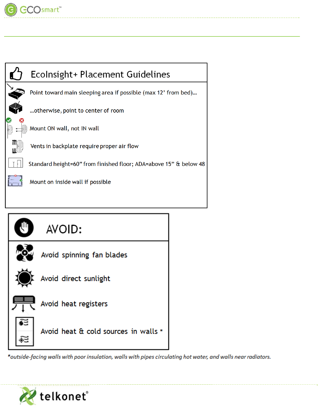
EcoInsight SS6010 Location Planning
EcoInsight+ SS6010
I, O & M Guide
Telkonet, Inc.
For Use with Firmware Version 2.x
20800 Swenson Drive, Suite 175
EcoInsight SS6010 Location Planning
Waukesha, WI 53186
Revision 2.1
(800) 380-9640
Page 5
www.telkonet.com
EcoInsight SS6010 Location Planning
EcoInsight SS6010 Location Planning
EcoInsight+ SS6010
I, O & M Guide
Telkonet, Inc.
For Use with Firmware Version 2.x
20800 Swenson Drive, Suite 175
EcoInsight SS6010 Location Planning
Waukesha, WI 53186
Revision 2.1
(800) 380-9640
Page 6
www.telkonet.com
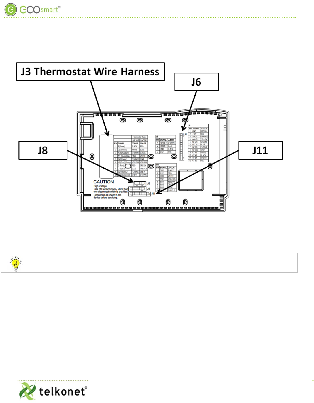
Figure 1: SS6010 Backplate
Wire harness tables appear in the Pinout Tables section, beginning on Page 30.
High Voltage Installation (Non-Class 2)
EcoInsight+ SS6010
I, O & M Guide
Telkonet, Inc.
For Use with Firmware Version 2.x
20800 Swenson Drive, Suite 175
High Voltage Installation (Non-Class 2)
Waukesha, WI 53186
Revision 2.1
(800) 380-9640
Page 7
www.telkonet.com
High Voltage Installation (Non-Class 2)
(Note: for Low Voltage Installation instructions, see page 16.)
Required Equipment
SS6010 (included)
High Voltage Backplate (included)
Molex harnesses as applicable (included)
Telkonet High Voltage JBOX Adapter Plate
(included)
JBOX
Two #6-32 1” screws
Four #5 ½” coarse thread screws Voltmeter
Level
Phillips screwdriver
UL rated insulating tape
Wire stripper
Wire nuts
Installation
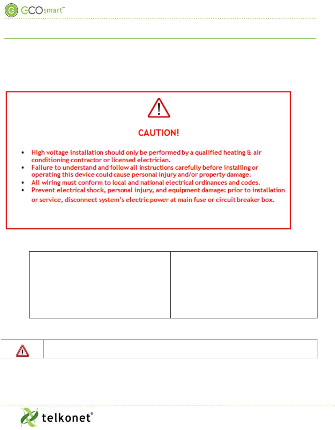
For all high voltage installations a single gang mud ring must be mounted VERTICALLY on a
JBOX. A Telkonet JBOX Adapter Plate is required for all JBOX installations.

High Voltage Installation (Non-Class 2)
EcoInsight+ SS6010
I, O & M Guide
Telkonet, Inc.
For Use with Firmware Version 2.x
20800 Swenson Drive, Suite 175
High Voltage Installation (Non-Class 2)
Waukesha, WI 53186
Revision 2.1
(800) 380-9640
Page 8
www.telkonet.com
1. Ensure the JBOX has been installed with a vertical single gang mud ring. See Figure 15: Vertical Single
Gang Mud Ring and Figure 17-JBOX Vertical Mounting Single Gang Mud Ring, both in Appendix B
beginning on page 35.
2. Turn off power at SS6010 or mounting location using a disconnect switch or breaker lockout/tag out on
appropriate breaker panel.
3. Test that power is off by using a voltmeter.
4. Strip the LINE wire back 0.25 inches.
5. Cap the LINE wire with a wire nut or electrical tape.
6. Cut the COMMON wire so the copper is flush with the insulation.
7. Strip all wires except for COMMON back 0.25 inches.
8. If using an adapter plate, determine which end of the adapter plate should be installed as the top, and
which end should be installed as the bottom:
Figure 2-Adapter Plate
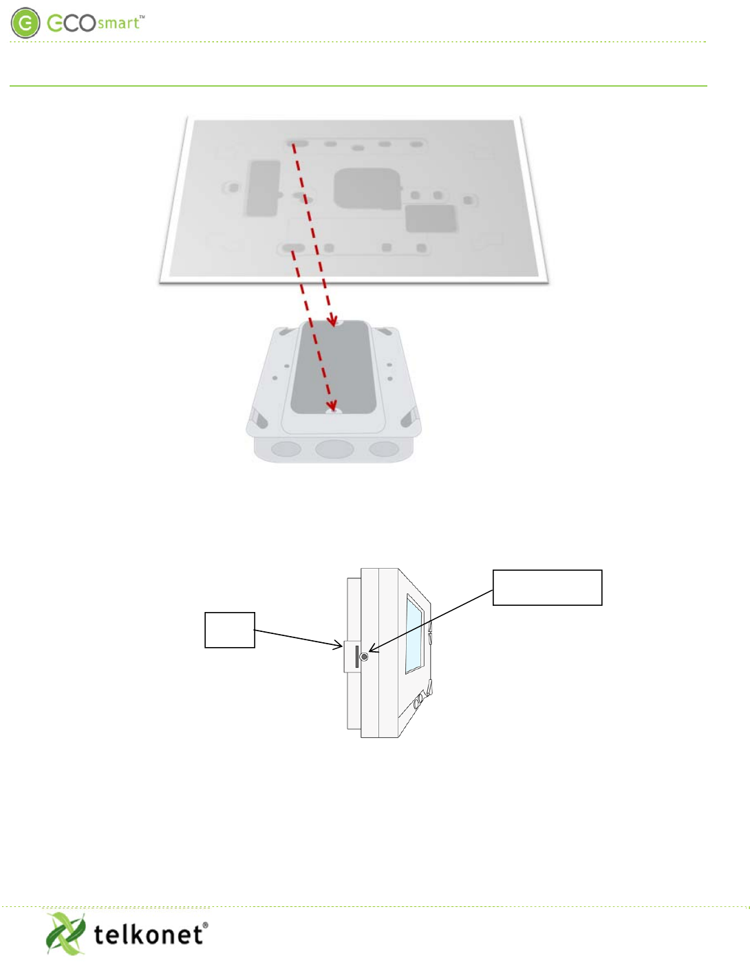
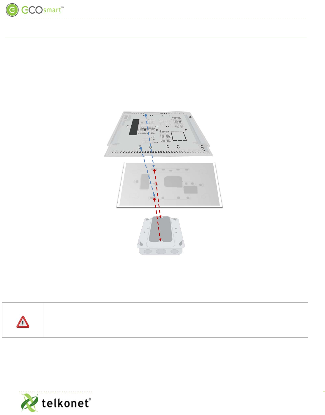
9. Level the high voltage Telkonet JBOX adapter plate and mount to the mud ring with two #6-32 1”
screws. See Figure 3.
High Voltage Installation (Non-Class 2)
EcoInsight+ SS6010
I, O & M Guide
Telkonet, Inc.
For Use with Firmware Version 2.x
20800 Swenson Drive, Suite 175
High Voltage Installation (Non-Class 2)
Waukesha, WI 53186
Revision 2.1
(800) 380-9640
Page 9
www.telkonet.com
Figure 3: JBOX, Mud Ring, Adapter Plate
10. Remove the safety screw from the left side of the SS6010 using the hex wrench. See Figure 4.
Figure 4: Thermostat Side View
11. Separate the high voltage back plate from the thermostat: use a flathead screwdriver to GENTLY press
the tab next to the screw hole to allow the thermostat to pop open. WARNING: Using too much force
can break the tab.
Safety Screw
Tab
High Voltage Installation (Non-Class 2)
EcoInsight+ SS6010
I, O & M Guide
Telkonet, Inc.
For Use with Firmware Version 2.x
20800 Swenson Drive, Suite 175
High Voltage Installation (Non-Class 2)
Waukesha, WI 53186
Revision 2.1
(800) 380-9640
Page 10
www.telkonet.com
12. Place thermostat backplate against the JBOX adapter plate. The adapter plate and backplate holes
should align if both are correctly oriented. See Figure 5.
13. Connect wires and harnesses as per the pinout tables in the Tables section, which begins on page 30.
14. Mount SS6010 backplate on top of JBOX adapter plate, using four #5 ½” coarse thread screws (or other
appropriate mounting screws).
Figure 5: Back Plate on Adapter Plate
15. Feed wire harnesses through the applicable holes in the backplate.
16. Connect the harnesses to the SS6010.
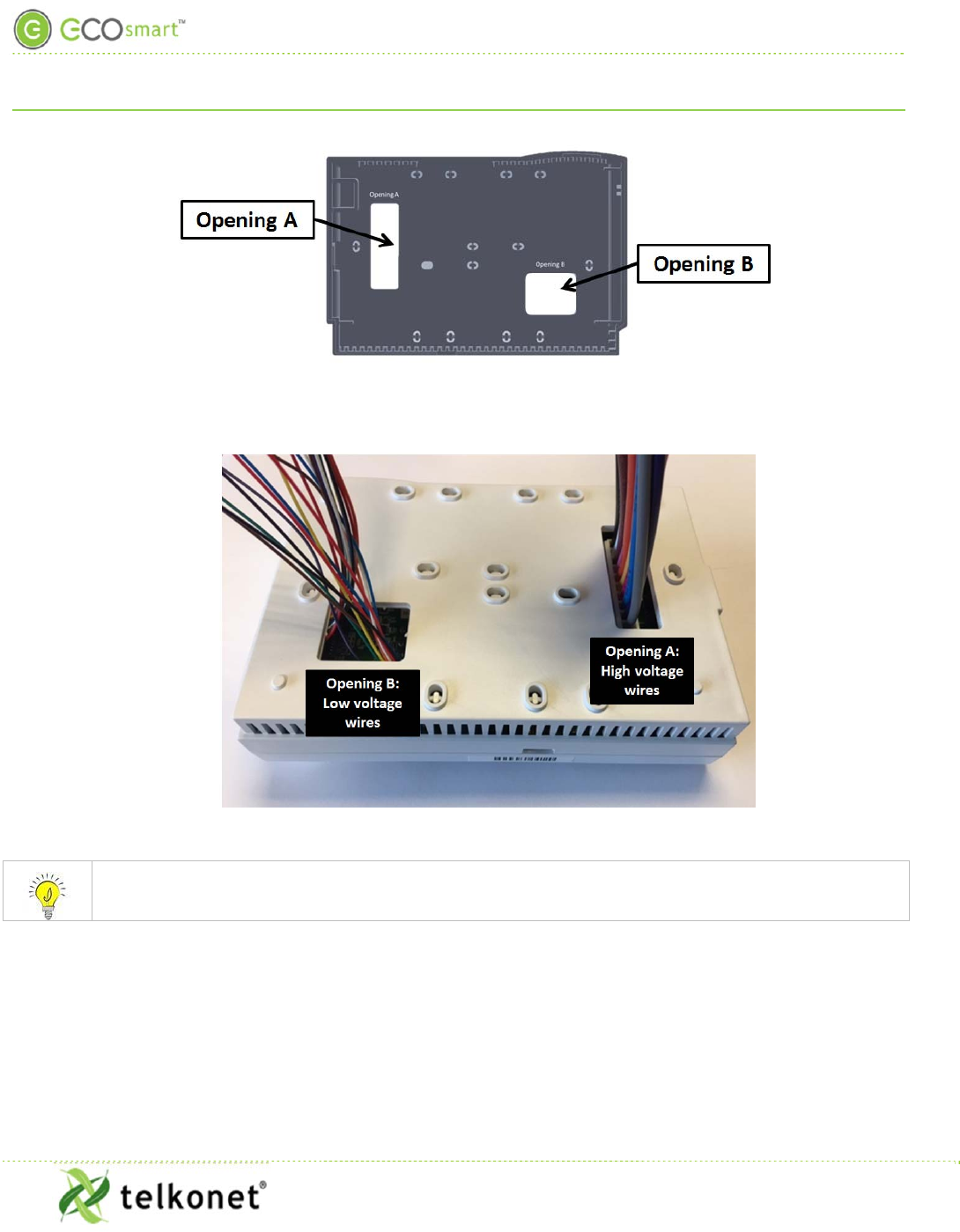
REMINDER: Wiring to J3 must exit the enclosure at Opening A of the backplate as shown in
Figure 6 and Figure 7 (page11). Wiring to all other connectors must exit the enclosure at
Opening B of the backplate.
Class 2 and Non-Class 2 wiring must not be mixed within a junction box or conduit run.
High Voltage Installation (Non-Class 2)
EcoInsight+ SS6010
I, O & M Guide
Telkonet, Inc.
For Use with Firmware Version 2.x
20800 Swenson Drive, Suite 175
High Voltage Installation (Non-Class 2)
Waukesha, WI 53186
Revision 2.1
(800) 380-9640
Page 11
www.telkonet.com
Figure 6-Separate High and Low Voltage Wires
Figure 7-Another View: Separate High and Low Voltage Wires
For variable output connections, see Appendix B, page 35.
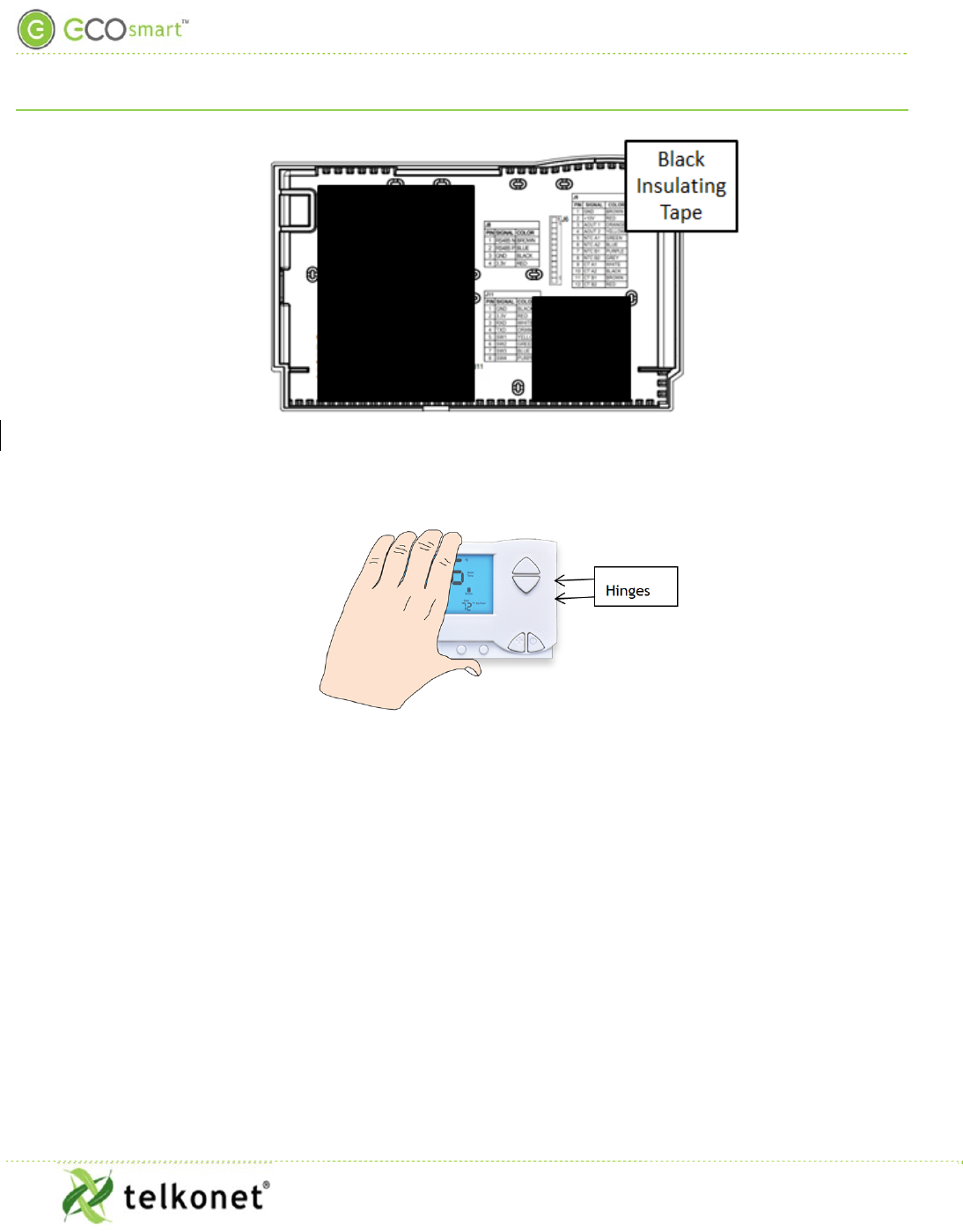
1. Ensure no airflow from JBOX or wall cavity is able to seep into the thermostat through the wire
harness. Telkonet recommends the use of UL caulk or UL rated insulating tape as shown in Figure 8 to
avoid false temperature readings.
High Voltage Installation (Non-Class 2)
EcoInsight+ SS6010
I, O & M Guide
Telkonet, Inc.
For Use with Firmware Version 2.x
20800 Swenson Drive, Suite 175
High Voltage Installation (Non-Class 2)
Waukesha, WI 53186
Revision 2.1
(800) 380-9640
Page 12
www.telkonet.com
Figure 8: Backplate with UL-Rated Insulating Tape
2. Line up the hinges on the thermostat to the notches on the backplate. See Figure 9
Figure 9: Line Up Hinges on Right
3. Press the right side of the thermostat tightly against the back plate.
4. Slowly bring the left side toward the wall. Use care not to force the faceplate closed. If you encounter
resistance, check to make sure no wires are pinched between components.
5. Return the electrical circuit to operation. Remove all lockouts or tags from the circuit breaker and
enable any disconnects.
6. Verify the SS6010 thermostat display is active.
7. Test all components to make sure that you can engage both the heat and cool, and all supported fan
settings (high, low, etc.). Wiring is complete.
8. Once the thermostat has been snapped onto the back plate, use a hex wrench to insert the safety
screw.
High Voltage Installation (Non-Class 2)
EcoInsight+ SS6010
I, O & M Guide
Telkonet, Inc.
For Use with Firmware Version 2.x
20800 Swenson Drive, Suite 175
High Voltage Installation (Non-Class 2)
Waukesha, WI 53186
Revision 2.1
(800) 380-9640
Page 13
www.telkonet.com
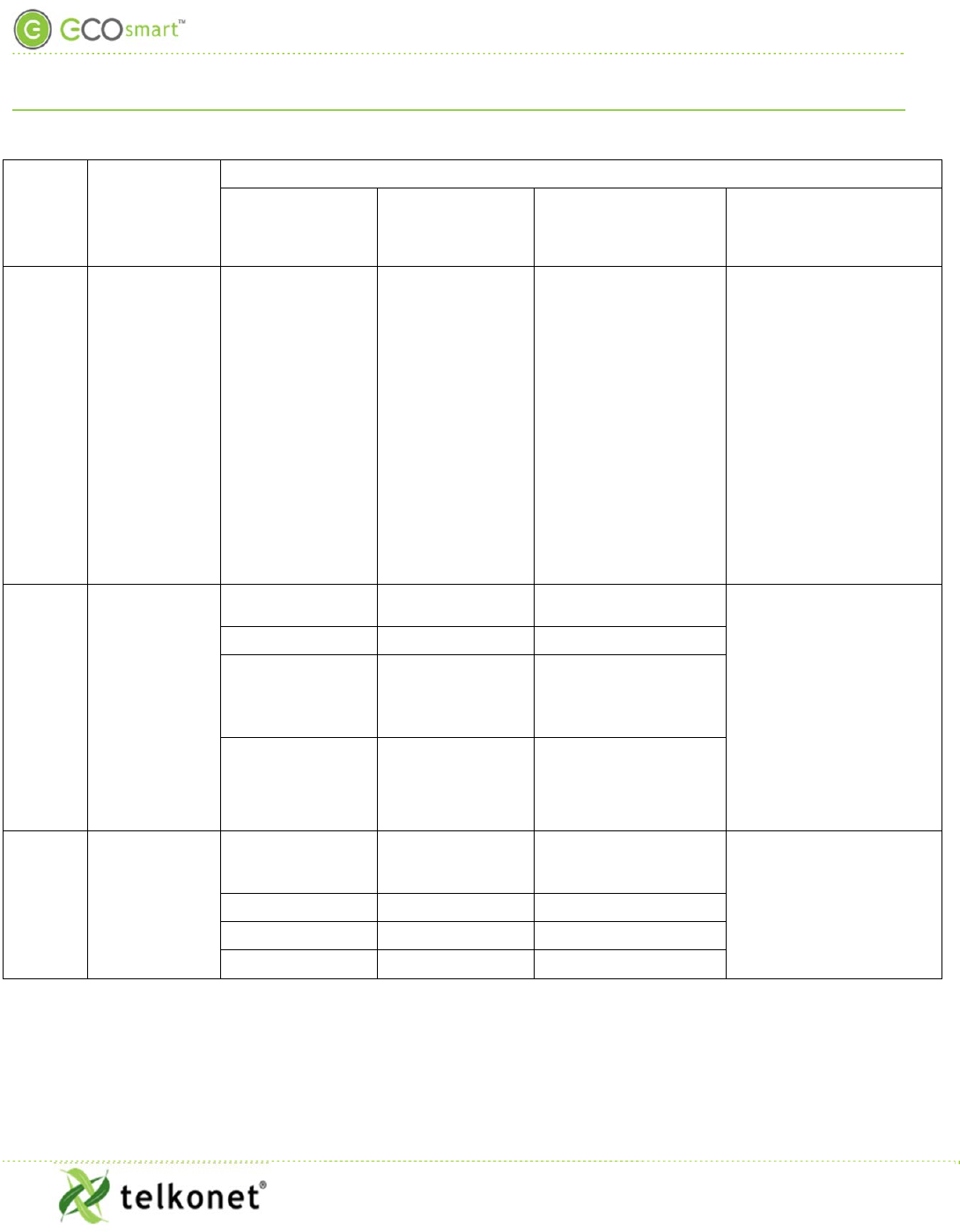
Rating Schedule – Non-Class 2
INPUTS:
Input Type (i.e. Supply, Sensor,
Communication) Terminals Input Rating
Communication J8, J9, J10, J11
3.3 Vdc max. Class 2, SELV, Low
Power (Less than 15 watts)
See Note 4
Accessible communications: RS232 J12 5 Vdc max.
Class 2, SELV, Low Power
(Less than 15 watts)
Power Supply J3-1 (R) and J3-2 (C) 30 –
277VAC
See Note 4
High Voltage Installation (Non-Class 2)
EcoInsight+ SS6010
I, O & M Guide
Telkonet, Inc.
For Use with Firmware Version 2.x
20800 Swenson Drive, Suite 175
High Voltage Installation (Non-Class 2)
Waukesha, WI 53186
Revision 2.1
(800) 380-9640
Page 14
www.telkonet.com
OUTPUTS (+):
Position
Relay Terminal
Ratings
Current / power Voltage Load type Action Type Design
RLY1,
RLY2,
RLY3
RLY1:J3-1 (R)
and
J3-3 (AUX)
RLY2:J3-5
(W1/Y1)
and
J3-4 (W1)
RLY3:J3-5
(W1/Y1)
and
J3-6 (Y1)
See note 1
5A 125/250/277
VAC General use Operating
1.C
RLY5,
RYL7
RLY5: J3-9
(G/O/W2) and
J3-7 (G)
See Note 3
RLY7: J3-9
(G/O/W2)
and
J3-8 (O)
See Note 3
See Note 1
10A 125 VAC General use
Operating
1.C
8A 277 VAC General use
1/10HP 125 VAC Motor
1/6HP 250 VAC &
277 VAC Motor
RLY8
J3-9
(G/O/W2)
and
J3-10 (W2)
See Note 3
See Note 1
16A 277 VAC
Resistive (including
Fixed Electric Space
Heating) See Note 2 Operating
1.A.Y
See Note 2
1HP 250 VAC Motor
1HP 277 VAC Motor
½HP 125 VAC Motor
Note 1: J3-1 (R), J3-5 (W1/Y1), and J3-9 (G/O/W2) – must be connected to the same pole of the same supply
circuit. Relay contacts must be connected in a same polarity fashion.
Note 2: Relay RLY8 is the only output device rated for the control of fixed electric space heating
equipment. This relay will de-energize when the On/Off switch is adjusted to the “OFF” position. RLY8 only

High Voltage Installation (Non-Class 2)
EcoInsight+ SS6010
I, O & M Guide
Telkonet, Inc.
For Use with Firmware Version 2.x
20800 Swenson Drive, Suite 175
High Voltage Installation (Non-Class 2)
Waukesha, WI 53186
Revision 2.1
(800) 380-9640
Page 15
www.telkonet.com
interrupts one pole of the supply circuit. Accordingly, the thermostat/relay is restricted to controlling fixed
electric space heating loads with a single ungrounded conductor – such as loads connected to a 120 or 277 Vac
circuit.
Note 3: The total connected load of Relays 5, 7 and 8 should not exceed 16 Amps (through common terminal
J3-9).
Note 4: Wiring to J3 must exit the enclosure at Opening A of the backplate as shown in Figure 6 and Figure 7
(page11). Wiring to all other connectors must exit the enclosure at Opening B of the backplate. Class 2 and
Non-Class 2 wiring must not be mixed within a junction box or conduit run.

Low Voltage Installation (Class 2)
EcoInsight+ SS6010
I, O & M Guide
Telkonet, Inc.
For Use with Firmware Version 2.x
20800 Swenson Drive, Suite 175
Low Voltage Installation (Class 2)
Waukesha, WI 53186
Revision 2.1
(800) 380-9640
Page 16
www.telkonet.com
Low Voltage Installation (Class 2)
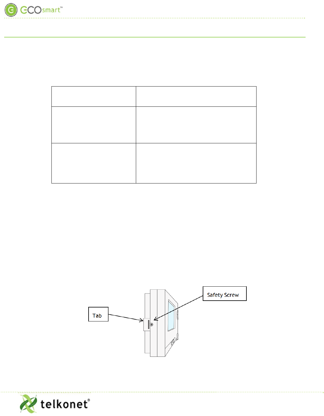
Always ensure power has been turned off before starting installation.
Required Equipment
SS6010 (included)
Wire harnesses as applicable (included)
Voltmeter
Level
Phillips Head Screwdriver
Wire nuts
Precision Screwdriver
UL rated insulating tape
Wire stripper
Speed nut (if applicable)
Low Voltage Installation (Class 2)
EcoInsight+ SS6010
I, O & M Guide
Telkonet, Inc.
For Use with Firmware Version 2.x
20800 Swenson Drive, Suite 175
Low Voltage Installation (Class 2)
Waukesha, WI 53186
Revision 2.1
(800) 380-9640
Page 17 www.telkonet.com
Additional Hardware:
Drywall Mount:
4 –
50 lb. EZ-Lock anchors and
provided screws
VERTICAL JBOX Mount:
Telkonet JBOX Adapter Plate
Two #6-32 1” screws
Four #5 ½” coarse thread screws
HORIZONTAL JBOX Mount: Two #6-32 1” screws
Installation
1. If applicable, determine the location in the room where the thermostat will be installed. (See
SS6010 Location Planning section, page 5.)
2. Turn off power at SS6010 mounting location using a disconnect switch or breaker lockout/tag
out on appropriate breaker panel.
3. Test that power is off by using a voltmeter.
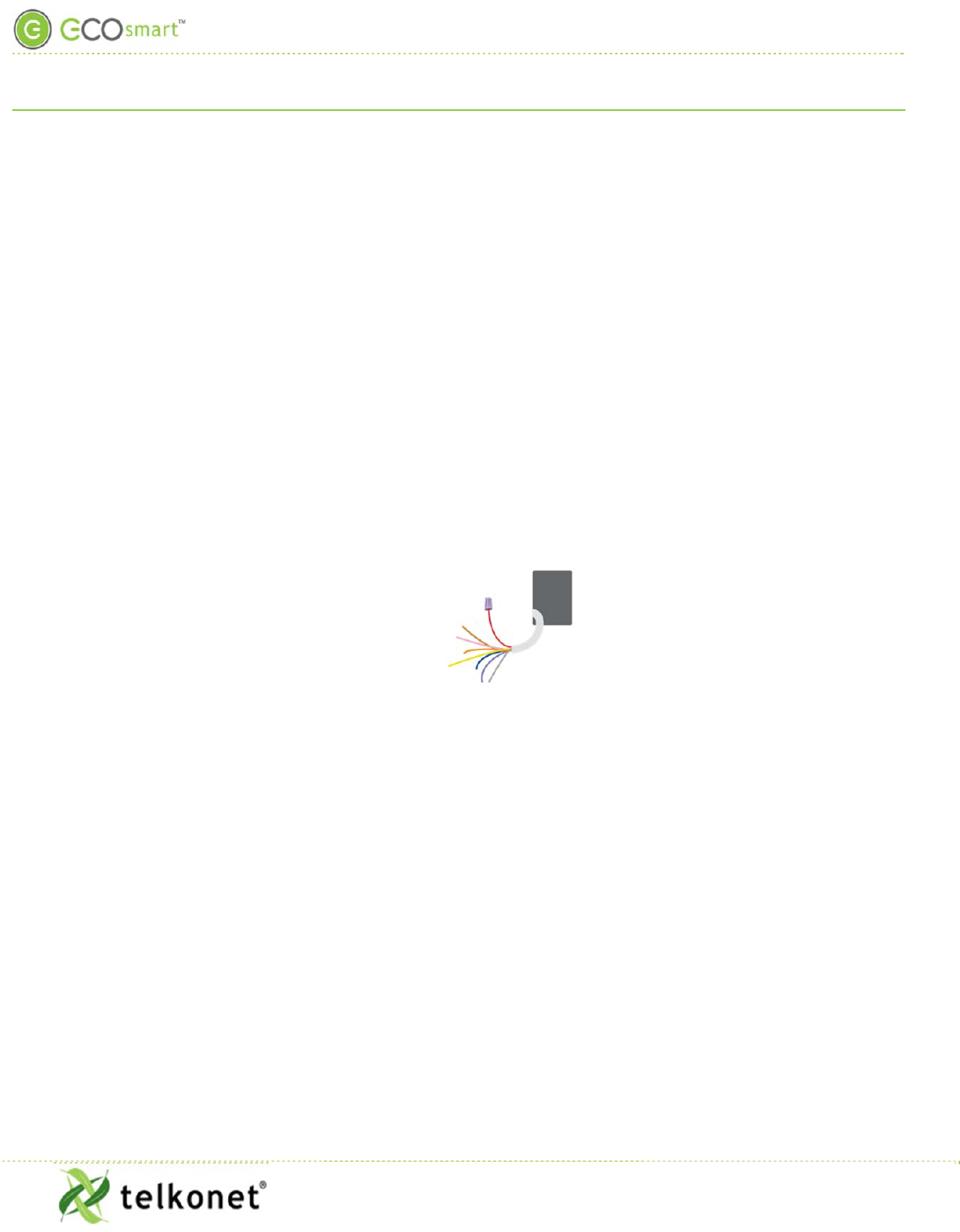
4. Remove the safety screw from the left side of the thermostat using the hex wrench. See
Figure 10.
Figure 10: Thermostat Side View
Low Voltage Installation (Class 2)
EcoInsight+ SS6010
I, O & M Guide
Telkonet, Inc.
For Use with Firmware Version 2.x
20800 Swenson Drive, Suite 175
Low Voltage Installation (Class 2)
Waukesha, WI 53186
Revision 2.1
(800) 380-9640
Page 18 www.telkonet.com
5. Separate the back plate from the thermostat: Use a flathead screwdriver to GENTLY press the
tab next to the screw hole to allow the thermostat to pop open. WARNING: Using too much
force can break the tab.
For drywall mounting instructions, see below.
For JBOX vertical installation instructions, go to page 18
For JBOX horizontal installation instructions, go to page
Drywall Mounting Instructions
Requires four 50 lb. EZ-Lock anchors and provided screws
6. Strip the LINE wire back 0.25 inches.
7. Cap the LINE wire with a wire nut or electrical tape.
8. Cut the COMMON wire so the copper is flush with the insulation.
9. Strip all wires except for COMMON back 0.25 inches.
10. Verify the wiring now looks similar to Figure 11.
Figure 11: Drywall Mount Wiring
11. Ensure the wiring Molex has appropriate wires jumped between R, SW1 and SW2 (assuming
they are controlling all fan and modes from the same voltage as powering the thermostat). If
installing on a heat pump, ensure that Y1 and W1 are jumped together.
12. Connect wires and harnesses as per the tables in the Tables section, which begins on page 30.
13. Verify each wire is secure by gently tugging on it.
14. Hold backplate against wall at appropriate height. Using a pen, level-mark your 4 holes.
15. Use appropriate drill for anchor and insert anchors into holes.
16. Screw backplate to the wall and into the anchors. Re-check that it is still level.
17. Connect the harnesses to the SS6010.
18. Continue to Step 35 (on page 19).
JBOX Using Vertical Mud Ring Instructions
Requires Telkonet JBOX Adapter Plate and two #6-32 1” screws

Low Voltage Installation (Class 2)
EcoInsight+ SS6010
I, O & M Guide
Telkonet, Inc.
For Use with Firmware Version 2.x
20800 Swenson Drive, Suite 175
Low Voltage Installation (Class 2)
Waukesha, WI 53186
Revision 2.1
(800) 380-9640
Page 19 www.telkonet.com
19. Strip the LINE wire back 0.25 inches.
20. Cap the LINE wire with a wire nut or electrical tape.
21. Cut the COMMON wire so the copper is flush with the insulation.
22. Strip all wires except for COMMON back 0.25 inches.
23. Determine which end of the adapter should be situated on top, and which end should be
situated on the bottom.
24. Mount the Telkonet JBOX adapter plate to the mud ring with two #6-32 1” screws.
25. Mount SS600 backplate on top of JBOX adapter plate, using four #5 ½” coarse thread screws.
26. Connect each Molex wire to the matching functional wire within the JBOX. Refer to
27. . (If controlling proportional valve or ECM fan, see Appendix B.) Any unused wires must be
capped according to NEC standards.
For variable output connections, see Appendix B on page 35.
28. Connect all other wires and harnesses as per the tables in the Tables section, which begins on
page 30.
29. Mount SS6010 backplate on top of JBOX adapter plate, using four #5 ½” coarse thread screws
30. Feed wire harnesses through the applicable holes in the backplate. High and low voltage
wires must be fed through separate holes as shown in Figure 7 (on page 11).
31. Connect the harnesses to the SS6010.
32. Ensure backplate has appropriate jumpers between R, SW1 and SW2. If installing on a head
pump, ensure there is a jumper between Y1 and W1.
33. Ensure no airflow from the JBOX or wall cavity is able to seep into the thermostat through the
wire harness. Telkonet recommends the use of approved UL caulk or UL rated insulating tape
to avoid false temperature readings. Figure 8 (page 12) illustrates sections of insulating tape
on the backplate, covering the wall opening.
34. Continue to Step 35 (on page 19).
Steps Common to all Installation Methods
35. Connect all Molex harnesses.
36. Hook the thermostat to the hinges on the right side of the backplate.
37. Line up the hinges on the thermostat to the notches on the backplate. Press the right side of
the thermostat tightly against the back plate.
Low Voltage Installation (Class 2)
EcoInsight+ SS6010
I, O & M Guide
Telkonet, Inc.
For Use with Firmware Version 2.x
20800 Swenson Drive, Suite 175
Low Voltage Installation (Class 2)
Waukesha, WI 53186
Revision 2.1
(800) 380-9640
Page 20 www.telkonet.com
38. Slowly bring the left side toward the wall as shown. Use care not to force the faceplate
closed. If you encounter resistance, make sure no wires are pinched between components and
that no pins are bent.
39. Once the thermostat has been snapped onto the back plate, use a hex wrench to insert the
safety screw in the location shown in Figure 10: Thermostat Side View on page 17.
40. Remove all lockouts or tags from the circuit breaker.
41. Return the electrical circuit to operation.
42. Verify the SS6010 thermostat display is active.
43. Test all components to make sure that you can engage both the heat and air conditioning,
and all supported fan settings (high, low, etc.). Wiring is complete.
44. Join, pair and bind. (See Device Association Guide for details.)
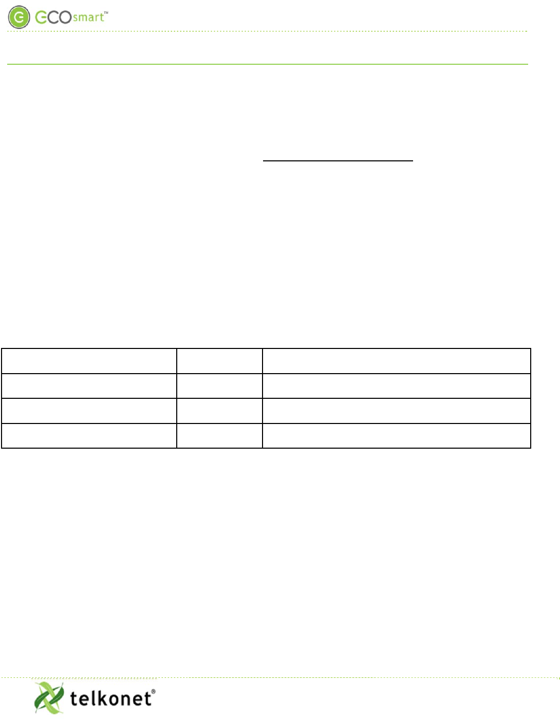
Rating Schedule– Class 2:
INPUTS:
Input Type (i.e. Supply, Sensor,
Communication) Terminals
Input Rating
Communication J8, J9, J10, J11
3.3 Vdc max. Class 2, SELV, Low Power (Less than 15
watts)
Accessible communications: RS232 J12 5 Vdc max.
Class 2, SELV, Low Power (Less than 15
watts)
Power Supply J3-1 (R) and J3-
2 (C) 24 Vac/Vdc (Nominal); 30 Vac/Vdc max. Class 2, SELV,
Low Power (Less than 15 watts)
Low Voltage Installation (Class 2)
EcoInsight+ SS6010
I, O & M Guide
Telkonet, Inc.
For Use with Firmware Version 2.x
20800 Swenson Drive, Suite 175
Low Voltage Installation (Class 2)
Waukesha, WI 53186
Revision 2.1
(800) 380-9640
Page 21 www.telkonet.com
OUTPUTS (+):
Position
Relay
Terminal Ratings per relay
Max. Voltage Max. current,
A Max. power, VA
Load type Action Type
Design.
RLY1,
RLY2,
RLY3,
RLY5,
RYL7,
RLY8
RLY1:J3-1 (R)
and J3-3 (AUX)
RLY2:J3-5
(W1/Y1) and J3-
4 (W1)
RY3:J3-5
(W1/Y1) and J3-
6 (Y1)
RLY5: J3-9
(G/O/W2) and
J3-7 (G)
RLY7: J3-9
(G/O/W2) and
J3-8 (O)
J3-9 (W2) and
J3-10
30 Vac/ Vdc,
Class 2, SELV 5
100
General use Operating
1.C

Add-Ons
EcoInsight+ SS6010
I, O & M Guide
Telkonet, Inc.
For Use with Firmware Version 2.x
20800 Swenson Drive, Suite 175
Add-Ons
Waukesha, WI 53186
Revision 2.1
(800) 380-9640
Page 22 www.telkonet.com
Add-Ons
About Wiring
The SS6010 interconnects with the existing HVAC system via standard wiring conventions, using 24-277VAC OR
24VDC voltage supplied by the HVAC system itself.
Note: The SS6010 does not allow three different power sources, as the SS6600 does. On the SS6010, all three
poles must be connected to the same power source.
The SS6010 does not support wiring directly, as the SS6600 does. Instead, we provide bare leads. It is up to the
installer to connect these leads using an appropriate method described herein. Wiring conventions follow
industry standards; however, it is important to note that the relay configuration is dynamic and can be
modified at the factory or in the field. It is important to always follow site-specific wire diagrams.
Relay Configuration
The thermostat comes with a default relay configuration, which sets the functions of each pin. This default can
be changed to one of several alternate relay configurations, which are stored in the memory of the thermostat.
To change your thermostat relay configuration, see Maintenance Menu
Table 6, specifically command #2.
Speed Configurations
The SS6010 will ship with a default speed configuration that matches the default relay configuration. The
speed configuration controls the timing of shifts between both fan speeds and stages of HVAC for compressor
based systems. The speed configuration will have a 3 minute safety delay between compressor cycles and upon
power up. The SS6010 also has several alternative embedded speed configurations. See Maintenance Menu
Table 6: Maintenance Menu Functions, specifically command #3.
NTC Probe
Temp probes can be used for multiple purposes:
1. HVAC Discharge Air temp
2. HVAC Return Air temp
3. Supply Water Temp
4. AquaStat Mode (switches thermostat’s Heat/Cool)
For temperature probe if not using Telkonet provided external temperature probe, a probe with a Beta R0 must
match. Alternatively, a probe can be provided to Telkonet for lab calibration. Required specifications:
US Sensor model USP10972 or equivalent, per the following:
Resistance at 25 degrees C = 10 000 ohms +/- 1%
Resistance/Temperature curve = "J"
Add-Ons
EcoInsight+ SS6010
I, O & M Guide
Telkonet, Inc.
For Use with Firmware Version 2.x
20800 Swenson Drive, Suite 175
Add-Ons
Waukesha, WI 53186
Revision 2.1
(800) 380-9640
Page 23 www.telkonet.com
Beta ( 0 to 50 degrees C ) = 3892 degrees K nominal
Other models may be compatible; provide model number and specifications.
Analog Outputs
See Appendix B
CT Inputs
All Models have 2 inputs. The CT inputs are commonly used for monitoring/alerting on fan motors, compressors
or other equipment with excessive load or for determining a failure. The CT Inputs must be used with a
compatible CT and sized appropriately for the load they will be connected to.
Current Transformer (CT) approved models from Sentran Corp.:
Rated loads are 100, 50, 30, 20 and 10 A respectively.
BCF-100A: 0.025A
LCF-50A: 0.025A
LCF-30A:0.025A
LCF-20A:0.025A
LCF-10A: 0.01A
Preferred operating range is between 10 and 80% of rated load.
Other models may be compatible: provide model number and specifications
If not sized correctly the CT may damage the thermostat.
User Interface
EcoInsight+ SS6010
I, O & M Guide
Telkonet, Inc.
For Use with Firmware Version 2.x
20800 Swenson Drive, Suite 175
User Interface
Waukesha, WI 53186
Revision 2.1
(800) 380-9640
Page 24 www.telkonet.com
User Interface
Panel Controls
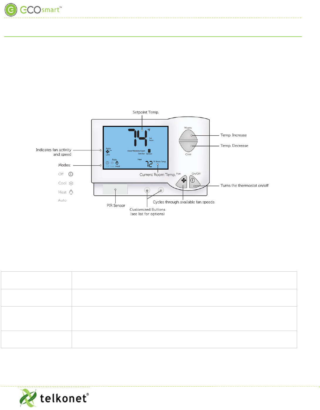
Front panel controls are shown below.
Figure 12: User Controls and Icons
The buttons on the SS6010 are designed to be easy to use and understand.
Table 1: SS6010 Buttons
Up/Down Arrows For occupants, the up and down arrows increment the setpoint temperature by
one degree.
On/Off Button The On/Off button typically toggles the power to the thermostat, but can be set
to cycle the Heat/Cool/Off modes as well.
Fan Button The Fan button either increments the fan speed or turns the fan on and off. This
function will depend on whether the property has independent fans or more than
one fan speed.
Soft Buttons The two soft buttons near the bottom of the thermostat can have numerous
functions, depending on the desire of the property. See Figure 13.
User Interface
EcoInsight+ SS6010
I, O & M Guide
Telkonet, Inc.
For Use with Firmware Version 2.x
20800 Swenson Drive, Suite 175
User Interface
Waukesha, WI 53186
Revision 2.1
(800) 380-9640
Page 25 www.telkonet.com
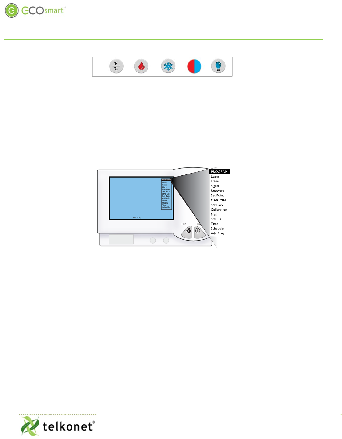
Figure 13: Soft Buttons
The most common uses for the soft buttons are Fahrenheit/Celsius, Heat, Cool, Heat/Cool.
Grey button: can be programmed for nearly any function the property chooses.
The Maintenance Menu
The Maintenance Menu is for approved staff to make adjustments to the operational settings of the SS6010.
Figure 14: The Maintenance Menu
Navigate the Maintenance Menu
Procedure: Display and Navigate the Maintenance Menu as shown in Figure 14.
Step 1 Press and hold the Fan button for 10 seconds.
Step 2 Press the On/Off button.
Step 3 Use the buttons on the face of the SS6010 to navigate through the Maintenance Menu.
Their functions are shown in Maintenance Menu
Table 6.
Step 4 The last menu item is “Advanced Programming”. When you press the up/down arrows to
scroll down to the bottom of the screen, the last menu item is Adv Prog, the screen will
display “Adv Prog” in the middle of the bottom of the screen. See Advanced Command
Menu
Table 7. All menu items are saved automatically when you set them.

Troubleshooting
EcoInsight+ SS6010
I, O & M Guide
Telkonet, Inc.
For Use with Firmware Version 2.x
20800 Swenson Drive, Suite 175
Troubleshooting
Waukesha, WI 53186
Revision 2.1
(800) 380-9640
Page 26 www.telkonet.com
Troubleshooting
Problem Potential Cause Potential Solution
HVAC unit does not operate.
Main electrical failure to the unit.
Many units operate on 230 or
277VAC circuits, so although power
is available to the 110VAC plugs in
the room, the branch circuit
supplying HVAC power may be
interrupted.
Dispatch maintenance. Verify
mains continuity to the unit.
GFI within the HVAC has tripped.
Some models of HVAC systems
(often PTAC/PTHP units) contain
integral GFI (Ground-Fault
Interrupt) systems. Occasionally,
often after a power outage, inrush
current when power returns can
cause GFIs to trip. Most times, this
does not indicate issues with the
unit.
Check and reset units’ GFI systems.
SS6010 has failed.
Replace the SS6010 with a known-
good unit as a comparison-check.
If the replacement unit functions
properly, contact Telkonet and
begin the RMA process.
If the replacement unit does not
function properly, consult a local
HVAC technician to inspect your
HVAC unit.
Door contact is not connected. Ensure that all door contacts are
connected.
Window or outside door is open. Ensure that no monitored windows
or patio doors are open.

Troubleshooting
EcoInsight+ SS6010
I, O & M Guide
Telkonet, Inc.
For Use with Firmware Version 2.x
20800 Swenson Drive, Suite 175
Troubleshooting
Waukesha, WI 53186
Revision 2.1
(800) 380-9640
Page 27 www.telkonet.com
Problem Potential Cause Potential Solution
Occupant returns to room and finds
it too hot or too cold.
During an Unoccupied period, the
EcoSmart system allows the
temperature in the room to drift
away from the occupants’ setpoint.
Telkonet’s Recovery Time
technology is enabled to return the
room to the occupants’ setpoint
within a time defined in advance
by the Property Manager (this
varies by property, but it usually
between 8 and 20 minutes).
Advise the occupant to wait 8 – 20
minutes. (This is the typical range
of defined Recovery Times
requested by customers in most
installations.)
Service sensor appears on
thermostat. One or more sensors have lost
association to the thermostat.
Dispatch Maintenance to the room.
Re-associate all sensors via
procedures.
Replace the batteries in all sensors
within the room.
Evaluate the wiring between each
sensor and the thermostat.
Occupant reports HVAC shuts down
while they sleep.
Sensor is not accurately detecting
occupancy. This is typically seen in
deployments where the bed
placement within the room was
changed after installation, such
that the pillow area of the bed(s)
is further than 10-15 feet from the
sensor.
Assess the room, sensor placement,
and bed location(s). Verify that the
sensor(s) are deployed in
accordance with the Recommended
Best Practices. Corrective
strategies may include:
a. Moving the sensor
b. Adding an additional sensor
to accommodate the new
room layout
c. Changing the room layout
d. Adjusting sensor settings
(contact Telkonet to discuss
options)
e. Adjusting night delay
(contact Telkonet support
for assistance)

Troubleshooting
EcoInsight+ SS6010
I, O & M Guide
Telkonet, Inc.
For Use with Firmware Version 2.x
20800 Swenson Drive, Suite 175
Troubleshooting
Waukesha, WI 53186
Revision 2.1
(800) 380-9640
Page 28 www.telkonet.com
Problem Potential Cause Potential Solution
Occupant reports one mode
(heating/cooling) works but the
other does not.
Heat pump jumper is reversed or
changeover signal is backwards, or
it may be that the heat/cool
jumpers are reversed.
Remove thermostat from
backplate, and identify jumper J3.
Insert jumper and replace
thermostat.
Room does not achieve setpoint
within Recovery Time.
The most common cause is that the
EcoSmart system is designed to
recover the temperature within a
Comfort Zone. The Comfort Zone is
programmable by Telkonet, and is
chosen by management before
installation.
The thermostat may be
programmed with settings not
appropriate to the specific
deployment scenario.
Contact Telkonet Customer
Support. Telkonet will research the
deployment history, and determine
whether a completed Settings
Sheet was provided to us prior to
thermostat shipment. Note that
Professional Services fees may
apply if a reported anomaly is later
determined to have been caused by
default settings when specific
preferences were not
communicated to Telkonet prior to
device shipment.
Often an HVAC unit is in need of
servicing. For example, a unit with
a failing compressor or under-
charged refrigerant may not be
able to efficiently return the room
to the occupants’ desired setpoint.
Ensure the PTAC unit is in good
working order.
Service and correct internal
thermostat anomalies per PTAC
manufacturer’s recommended best
practices.
There may be a failed control
circuit within the HVAC system
Ensure the PTAC unit is in good
working order.
Service and correct internal
thermostat anomalies per PTAC
manufacturer’s recommended best
practices.
The setpoint cannot be achieved
within the current environmental
conditions. For example, on an
extremely hot or humid day, the
HVAC system may not be able to
achieve a setpoint of 60°.
Ensure the PTAC unit is in good
working order.
Service and correct internal
thermostat anomalies per PTAC
manufacturer’s recommended best
practices.

Troubleshooting
EcoInsight+ SS6010
I, O & M Guide
Telkonet, Inc.
For Use with Firmware Version 2.x
20800 Swenson Drive, Suite 175
Troubleshooting
Waukesha, WI 53186
Revision 2.1
(800) 380-9640
Page 29 www.telkonet.com
Problem Potential Cause Potential Solution
Thermostat reboots repeatedly
The thermostat wiring is coming in
from the J8 hole and is placed
directly over the J8 pins on its way
to the terminal block.
Re-route the wiring along the
bottom of the backplate until
reaching the screw terminals.
Appendix A: Pinout Tables
EcoInsight+ SS6010
I, O & M Guide
Telkonet, Inc.
For Use with Firmware Version 2.x
20800 Swenson Drive, Suite 175
Appendix A: Pinout Tables
Waukesha, WI 53186
Revision 2.1
(800) 380-9640
Page 30 www.telkonet.com
Appendix A: Pinout Tables
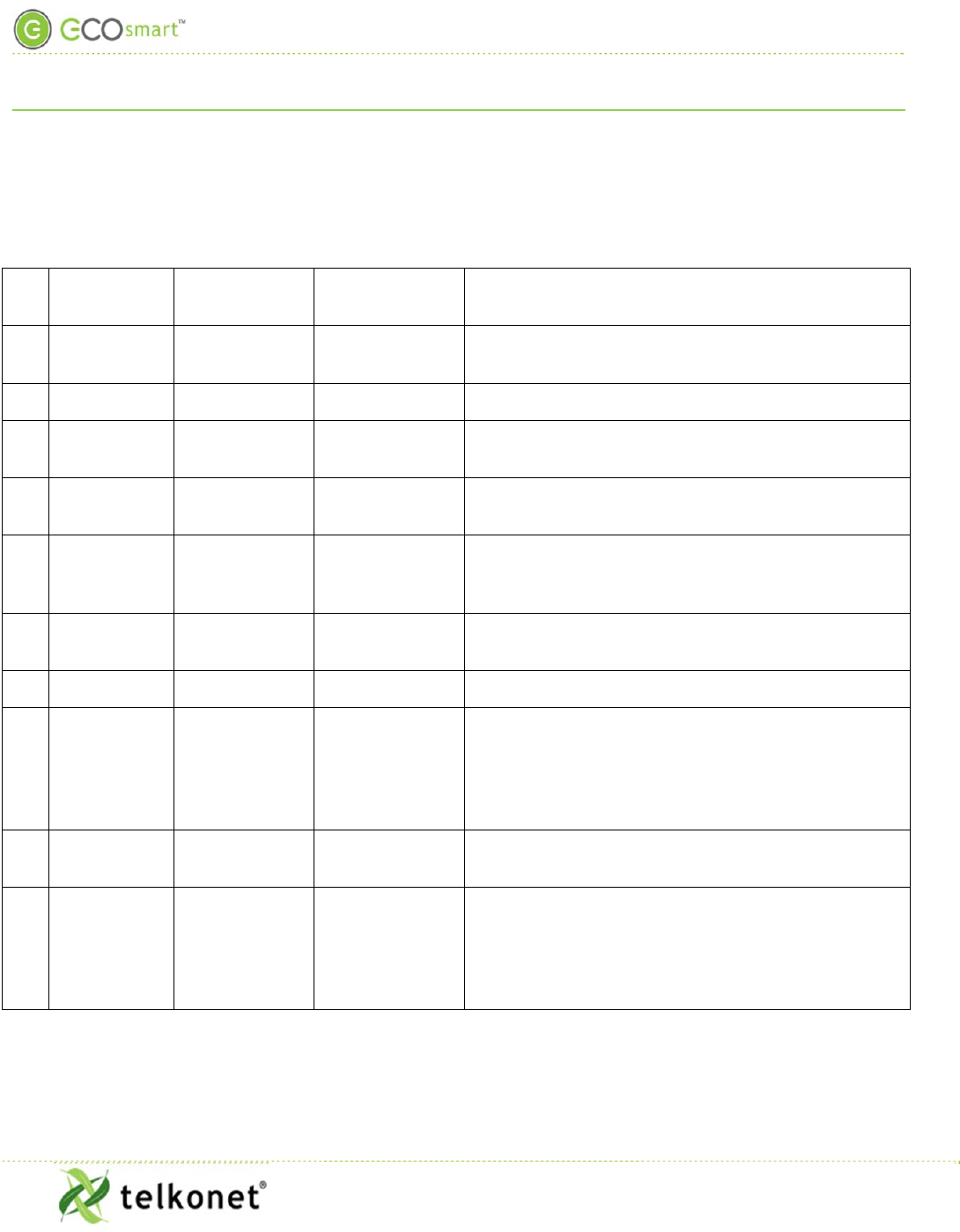
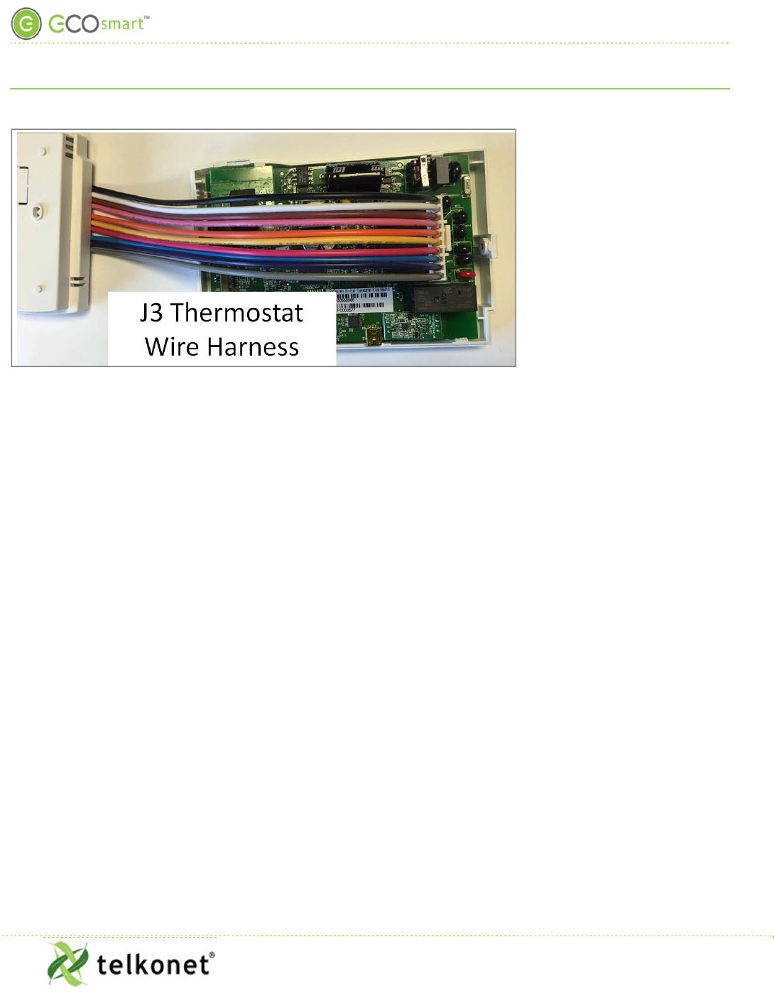
Table 2: J3 Thermostat Wiring Harness*
Pin Label on
Backplate High Voltage
Wire color Low Voltage
Wire color Function
1 R (Power) BLACK RED Power from HVAC, used to power the thermostat and
AUX output
2 C (Common) WHITE BLUE AC Common
3 AUX
(Auxiliary) BROWN BLACK User defined
4 W1 (Heat)
(Strip) PINK WHITE Heat call or strip heat call (depends on programming)
5 Switched
Power 1
(W1/Y1) ORANGE PINK Input for W1 and Y1
6 Y1 (Cool)
(Comp) YELLOW YELLOW Cool/Compressor call
7 G (Fan) RED GREEN Fan Call - Low speed
8 O (B) (G2)
(Y2)
(Changeover) BLUE ORANGE
Multi-use - depends on programming and site
requirements:
Changeover
2
nd
Stage Fan
2
nd
Stage Cooling
9 Switched
Power 2 PURPLE GREY Input for G, O, and W2
10
W2 (Y2) (G2)
(G3) (Multi-
speed) GREY BROWN
Multi-use - depends on programming and site
requirements:
2
nd
stage heat
Electric heat (for HPs with strip heat, etc.)
Emergency heat
* See the Rating Schedule section for electrical ratings and usage constraints.
Appendix A: Pinout Tables
EcoInsight+ SS6010
I, O & M Guide
Telkonet, Inc.
For Use with Firmware Version 2.x
20800 Swenson Drive, Suite 175
Appendix A: Pinout Tables
Waukesha, WI 53186
Revision 2.1
(800) 380-9640
Page 31 www.telkonet.com
Appendix A: Pinout Tables
EcoInsight+ SS6010
I, O & M Guide
Telkonet, Inc.
For Use with Firmware Version 2.x
20800 Swenson Drive, Suite 175
Appendix A: Pinout Tables
Waukesha, WI 53186
Revision 2.1
(800) 380-9640
Page 32 www.telkonet.com
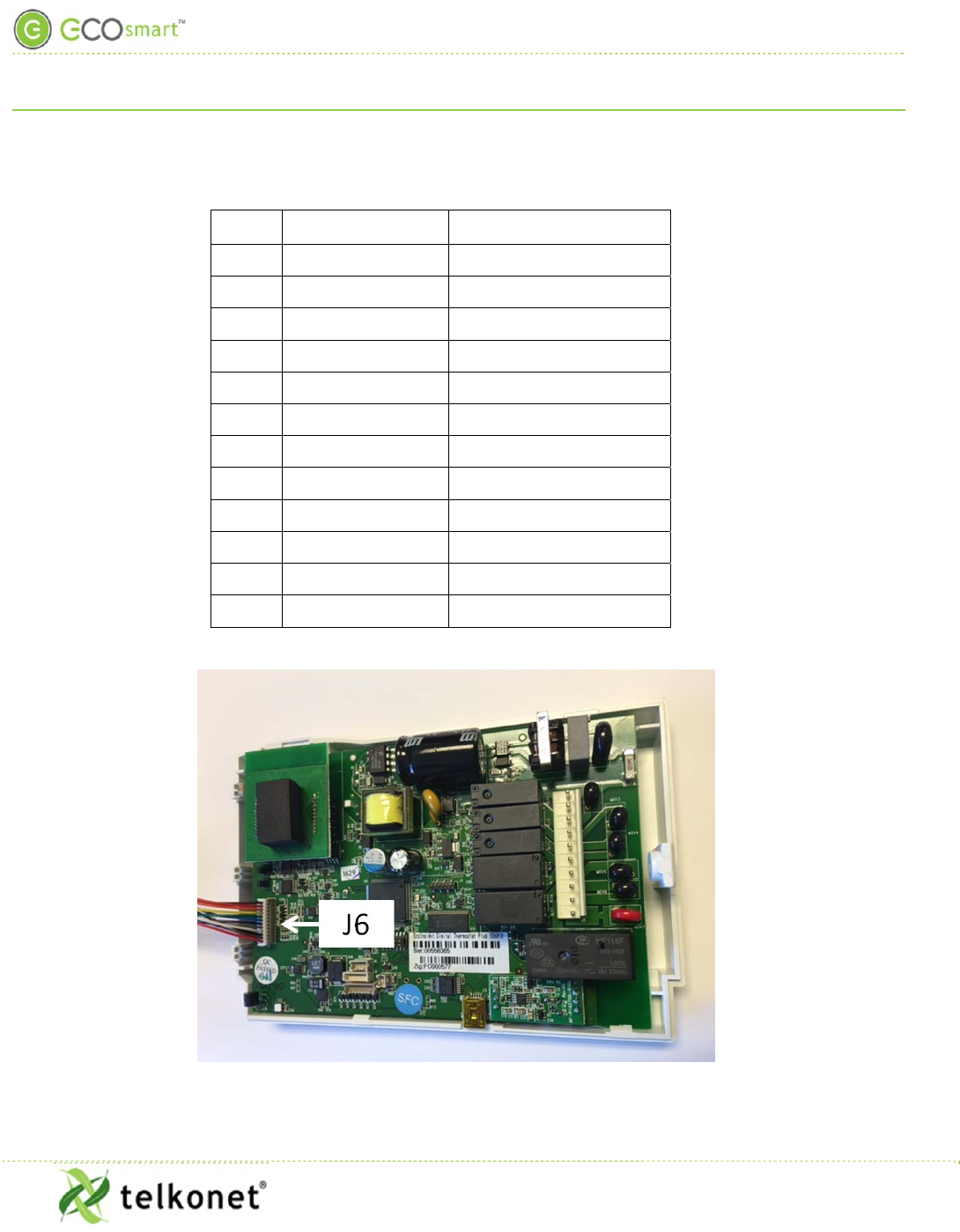
Table 3-J6 Pinout
PIN SIGNAL COLOR
1 GND BROWN
2 +10V RED
3 AOUT 1 ORANGE
4 AOUT 2 YELLOW
5 NTC A1 GREEN
6 NTC A2 BLUE
7 NTC B1 PURPLE
8 NTC B2 GREY
9 CT A1 WHITE
10 CT A2 BLACK
11 CT B1 BROWN
12 CT B2 RED
Appendix A: Pinout Tables
EcoInsight+ SS6010
I, O & M Guide
Telkonet, Inc.
For Use with Firmware Version 2.x
20800 Swenson Drive, Suite 175
Appendix A: Pinout Tables
Waukesha, WI 53186
Revision 2.1
(800) 380-9640
Page 33 www.telkonet.com
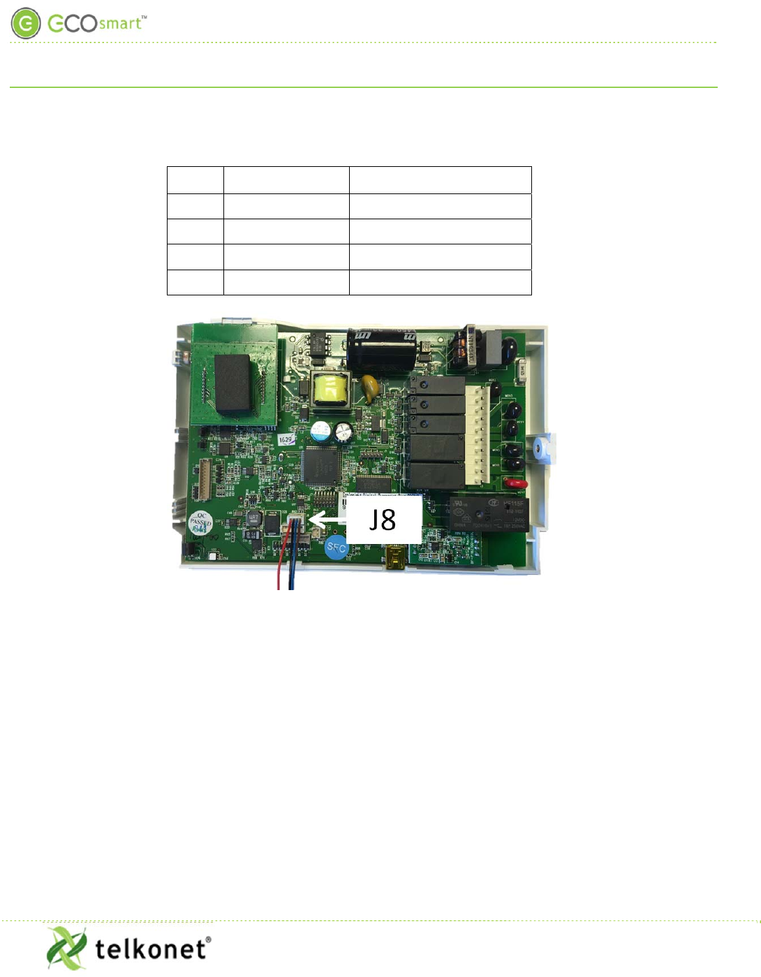
Table 4-J8 Pinout
PIN SIGNAL COLOR
1 RS485N BROWN
2 RS485P BLUE
3 GND BLACK
4 3.3V RED
Appendix A: Pinout Tables
EcoInsight+ SS6010
I, O & M Guide
Telkonet, Inc.
For Use with Firmware Version 2.x
20800 Swenson Drive, Suite 175
Appendix A: Pinout Tables
Waukesha, WI 53186
Revision 2.1
(800) 380-9640
Page 34 www.telkonet.com
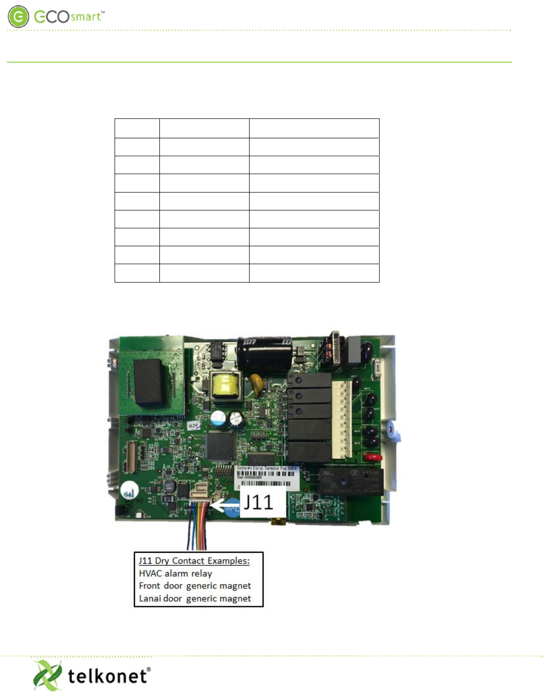
Table 5-J11 Pinout
PIN SIGNAL COLOR
1 GND BLACK
2 3.3V RED
3 RXD WHITE
4 TXD ORANGE
5 SW1 YELLOW
6 SW2 GREEN
7 SW3 BLUE
8 SW4 PURPLE
Appendix B
EcoInsight+ SS6010
I, O & M Guide
Telkonet, Inc.
For Use with Firmware Version 2.x
20800 Swenson Drive, Suite 175
Appendix B
Waukesha, WI 53186
Revision 2.1
(800) 380-9640
Page 35 www.telkonet.com
Appendix B
Proportional Valve Control

Appendix B
EcoInsight+ SS6010
I, O & M Guide
Telkonet, Inc.
For Use with Firmware Version 2.x
20800 Swenson Drive, Suite 175
Appendix B
Waukesha, WI 53186
Revision 2.1
(800) 380-9640
Page 36 www.telkonet.com
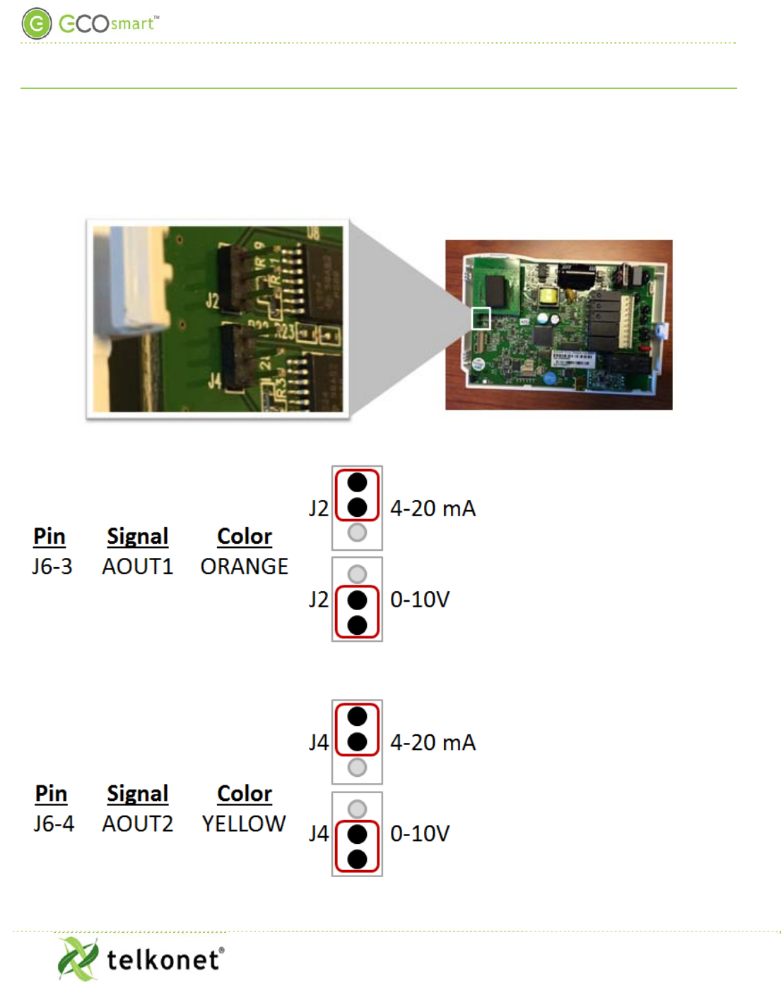
Analog Outputs
(VO model only)
The Analog outputs can be used to control multiple functions. The desired function must be specified at the
time of programming.
1. Fan Coils Variable Valve Control 0-10V or 4-20mA (Both Heat & Cool)
2. ECM Fan motor variable control between speeds. (0-10VDC)
Appendix C: JBOX Mounting Options
EcoInsight+ SS6010
I, O & M Guide
Telkonet, Inc.
For Use with Firmware Version 2.x
20800 Swenson Drive, Suite 175
Appendix C: JBOX Mounting Options
Waukesha, WI 53186
Revision 2.1
(800) 380-9640
Page 37 www.telkonet.com
Appendix C: JBOX Mounting Options
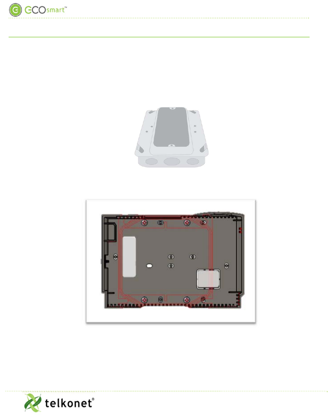
Figure 15: Vertical Single Gang Mud Ring & Single Gang Junction Box
Figure 16-JBOX Vertical Mounting with Double Gang Mud Ring, plus Adapter Plate
Appendix C: JBOX Mounting Options
EcoInsight+ SS6010
I, O & M Guide
Telkonet, Inc.
For Use with Firmware Version 2.x
20800 Swenson Drive, Suite 175
Appendix C: JBOX Mounting Options
Waukesha, WI 53186
Revision 2.1
(800) 380-9640
Page 38 www.telkonet.com
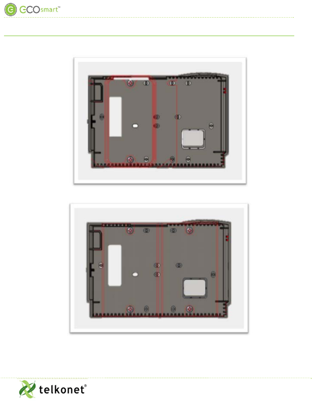
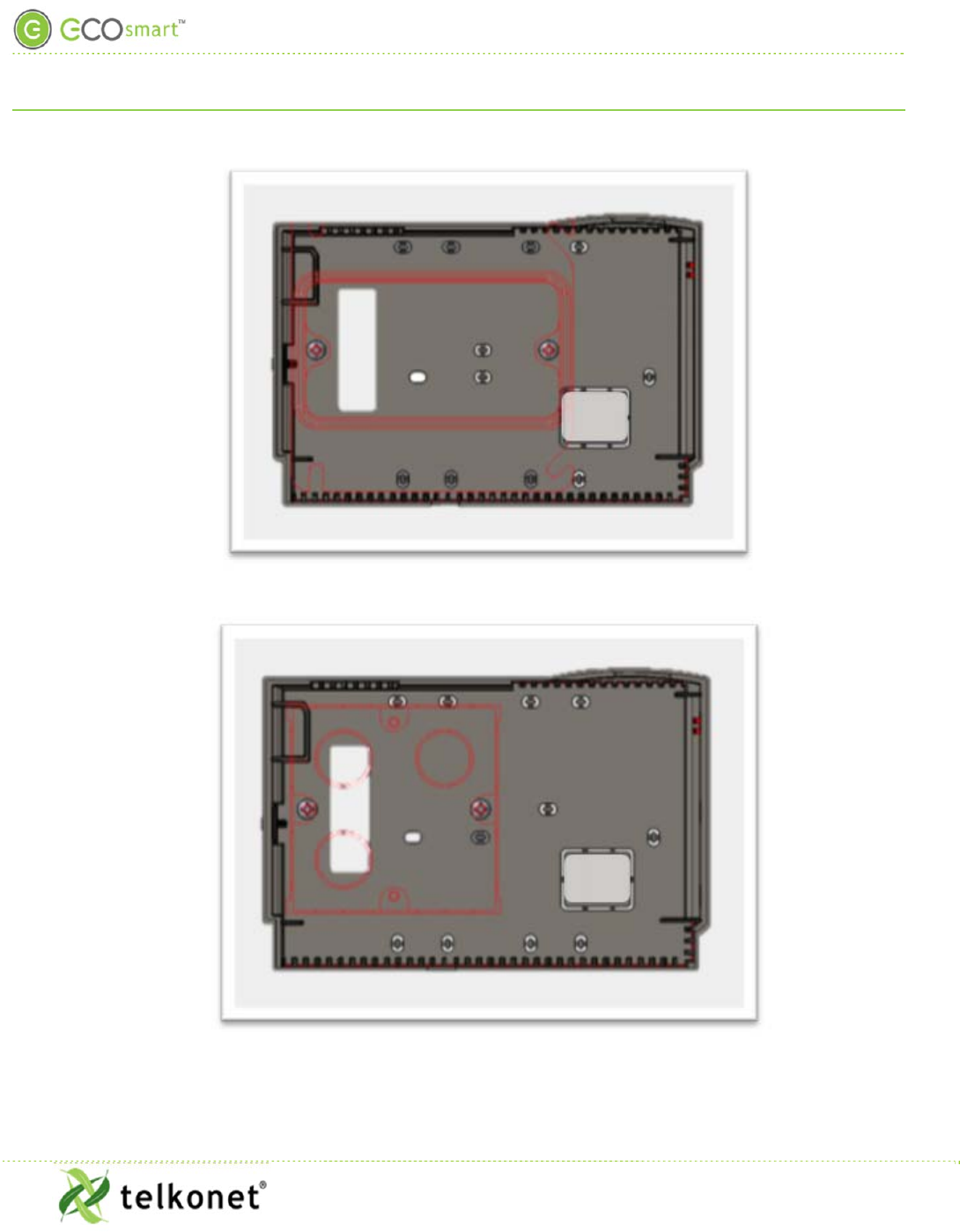
Figure 17-JBOX Vertical Mounting Single Gang Mud Ring, plus Adapter Plate
Figure 18-High Voltage with Low Voltage Connections to Separate Box, plus Adapter Plate
Appendix C: JBOX Mounting Options
EcoInsight+ SS6010
I, O & M Guide
Telkonet, Inc.
For Use with Firmware Version 2.x
20800 Swenson Drive, Suite 175
Appendix C: JBOX Mounting Options
Waukesha, WI 53186
Revision 2.1
(800) 380-9640
Page 39 www.telkonet.com
Figure 19-JBOX Horizontal Mounting Single Gang Mud Ring, plus Adapter Plate
Figure 20-European Mounting (Horizontal), plus Adapter Plate
Section: “Appendix D: Types of Radio Modules”
EcoInsight+ SS6010
I, O & M Guide
Telkonet, Inc.
For Use with Firmware Version 2.x
20800 Swenson Drive, Suite 175
Appendix D: Types of Radio Modules
Waukesha, WI 53186
Revision 2.1
(800) 380-9640
Page 40 www.telkonet.com
Appendix D: Types of Radio Modules
Internal high-power: default
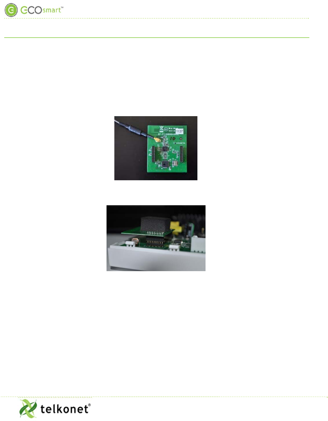
External high-power: An optional external antenna is available for systems that will be enclosed inside metal
HVAC systems to improve network reliability. See Figure 21 and Figure 22.
Figure 21: High-Power Radio Module with Antenna Attached
Figure 22: Radio Board Properly Seated
Regular Maintenance
EcoInsight+ SS6010
I, O & M Guide
Telkonet, Inc.
For Use with Firmware Version 2.x
20800 Swenson Drive, Suite 175
Regular Maintenance
Waukesha, WI 53186
Revision 2.1
(800) 380-9640
Page 41 www.telkonet.com
Regular Maintenance
Procedure: Visual Inspection
Step 1 Verify that components have not been tampered with, destroyed or stolen.
Step 2 Verify that the components are securely mounted on their respective surfaces.
Sensors may be mounted on walls or ceilings; either location is permissible and will have been
determined during installation.
Step 3 If applicable, verify that the AC power is being supplied to the HVAC system.
Step 4 If units are hard-wired, verify that the power/data wiring between the SS6010 and the
EcoSense are intact and connected.
Step 5 Check for a Service icon on the SS6010 display. This icon indicates loss of association with
one or more sensors.
Step 6 If the icon appears, first check the batteries. Replace batteries if necessary.
Step 7 If batteries are not the cause of the Service icon, erase and re-associate all sensors per
instructions in the EcoSmart Firmware 2.x Device Association Guide.
Procedure: Functional Inspection
Step 1 Observe whether the HVAC system is operating (e.g. drive cycle) after entering the room.
In most cases, entering the room will have initiated an HVAC drive cycle after the Sensor detected
occupancy. Possible exceptions:
-If the temperature in the room is within hysteresis of the HVAC setpoint, a drive cycle may not
commence
-A delay may have been programmed into the SS6010 thermostat, instructing the unit to wait for a
particular duration before triggering a drive. (Although uncommon, this feature is sometimes
requested by a property. In almost all cases, the delay is less than 3 minutes.)
Step 2 If a drive cycle does not initiate within 5 minutes of entry, force a drive cycle by
temporarily setting the thermostat to some arbitrary high or low temperature (ensure the
HVAC mode is set correctly).
SS6010 thermostats default to Occupied status if communication with the SS6010 or sensor(s) is lost
for any reason. This permits the units to continue to maintain the room temperature. However, in
this state energy savings will be lost. If in doubt whether the sensors are associated, re-associate all
Sensors per the EcoSmart Firmware 2.x Device Association Guide.

Maintenance Menu
EcoInsight+ SS6010
I, O & M Guide
Telkonet, Inc.
For Use with Firmware Version 2.x
20800 Swenson Drive, Suite 175
Maintenance Menu
Waukesha, WI 53186
Revision 2.1
(800) 380-9640
Page 42 www.telkonet.com
Maintenance Menu
Table 6: Maintenance Menu Functions
Menu Item Function
Learn Used to associate the SS6010 to other EcoSmart wireless devices in the room, such as an
EcoSense, EcoContact, EcoGuard, or EcoSwitch. For step-by-step instructions on associating
devices, see EcoSmart Firmware 2.x Device Association Guide.
Erase Will tell the SS6010 to forget all of the wireless devices it has been associated with, such as an
EcoSense, EcoContact, EcoGuard or EcoSwitch. The large number shown in the Erase menu
indicates the number of devices currently associated with the SS6010. Press On/Off to erase all
associated devices.
Signal Advanced command, which should only be changed with the assistance of Telkonet.
Recovery Sets the value for the number of minutes for Recovery Time. The number displayed indicates
the current recovery time, and can be incremented using the up or down arrows. Setting a
value of zero (0) will disable the energy manage set back feature.
Setpoint
MAX Indicates the current maximum temperature that a user can set. Can be incremented by using
the up and down arrows. This value must be lower than the MAX Setback.
Setpoint
MIN Indicates the current minimum temperature that a user can set. Can be incremented by using
the up and down arrows. This value must be higher than the MIN Setback.
MAX
Setback Indicates the maximum temperature a room can reach, either through guest setting or an
unoccupied drift.
MIN Setback Indicates the minimum temperature a room can reach, either through guest setting or an
unoccupied drift.
Calibration Allows authorized personnel to calibrate the ambient temperature to ensure accurate readings.
Mesh The Mesh submenu contains advanced commands for adjusting the ZigBee mesh network. These
options should only be changed with the assistance of Telkonet.
Stat ID This is an advanced command, which should only be changed with the assistance of Telkonet.
Time Allows authorized personnel to set the time on the thermostat.
Schedule If Schedules are in use, allows authorized personnel to select a schedule for the thermostat to
use.
Adv Prog This section contains multiple advanced commands that can be run on the SS6010. For details
on what Advanced Commands are available, please contact your Telkonet Project Manager or
Technical Support for a command list.

Advanced Command Menu
EcoInsight+ SS6010
I, O & M Guide
Telkonet, Inc.
For Use with Firmware Version 2.x
20800 Swenson Drive, Suite 175
Advanced Command Menu
Waukesha, WI 53186
Revision 2.1
(800) 380-9640
Page 43 www.telkonet.com
Advanced Command Menu
Table 7: Advanced Program Commands
Cmd
# Function
01 Profile: Selects one of the three default configurations stored in the thermostat. Note that these default
configurations are separate from the profiles available through Advanced Command 13 or EcoCentral.
02 Sets the desired relay configuration from available defaults.
Relay Config
-AdvCmd 02
Option to change between embedded default Relay Configs.
Embedded options will vary per customer. Talk to your Telkonet support representative to find out what
relay options are available within your firmware. Alternatively EcoSmart Serial Utility can be used to
make a custom relay config or to load a relay config file that is sent from the Telkonet support team.
03 Sets the desired speed configuration from available defaults.
Speed Config
-Adv Cmd 03
Option to change between embedded default speed configs.
Embedded options will vary per customer. Talk to your Telkonet support representative to find out what
speed config options are available within your firmware. Alternatively EcoSmart Serial Utility can be
used to make a custom speed config or to load a speed config file that is sent from the Telkonet support
team.
04 Sets the changeover value for Heat Pump operation (c/o heat).
05 Sets the changeover value for Heat Pump operation (c/o cool)
06 Sets the minimum temperature for Deep Setback mode*.
07 Sets the maximum temperature for Deep Setback mode*.
08 Choosing (01) selects a heat only interface, selecting (00) removes the heat only interface. If cool only
is also selected, the system will default to auto only.
09 Choosing (01) selects a cool only interface, selecting (00) removes the cool only interface. If heat only is
also selected, the system will default to auto only.
10 Sets the auto mode overshoot required for opposing mode to be called.
11 Sets the Door Contact configuration to N/O (00) or N/C (01) (normally open or normally closed).
12 Displays the RH% in the bottom right corner of the screen if RH sensor is installed.
13 Permanent Profiles:

Advanced Command Menu
EcoInsight+ SS6010
I, O & M Guide
Telkonet, Inc.
For Use with Firmware Version 2.x
20800 Swenson Drive, Suite 175
Advanced Command Menu
Waukesha, WI 53186
Revision 2.1
(800) 380-9640
Page 44 www.telkonet.com
Each SS6010 can hold 7 different collections of settings. Each collection of settings is defined as a
“profile”. Typically each SS6010 will ship with at least 3 profiles pre-loaded into the thermostats
memory. Most common will include:
Sold- This profile contains the settings for operating when a hotel room is in the Sold state from a PMS.
UnSold - This profile contains more aggressive setback temperature values because the room is not
rented.
VIP - This profile contains either no setback value or very restrictive setback for rooms that you do not
want to turn off the HVAC in.
Profiles are completely configurable by the facility and can be changed at any time with network
systems.
When using Advanced Command 13 to change the profile, the thermostat will continue
to operate in that profile until it is manually changed again, either through EcoCentral or the
front panel of the thermostat.
14 Temporary Profiles (not available at all locations)
Advanced Command 14 also changes the profile of the thermostat, but unlike
Advanced Command 13, it is a temporary change. The profile will only be in effect for
a set amount of time (for example, 24 hours) or until the room is unoccupied for
longer than a set amount of time (for example, no occupancy sensed for 8 consecutive
hours). After the required time has passed, the thermostat will revert to its previous
profile.
15 This changes the polarity of the relay for the Multi-speed pin, 0 means N/O, 1 means N/C.
16 This changes the polarity of the relay for the (O) changeover, 0 means N/O, 1 means N/C.
17 This changes the polarity of the relay for the (G) pin, 0 means N/O, 1 means N/C.
18 This changes the polarity of the relay for the (Y1) cooling pin, 0 means N/O, 1 means N/C.
19 This changes the polarity for the (W1) heating , 0 means N/O, 1 means N/C.
20 This changes the polarity of the relay for the AUX, 0 means N/O, 1 means N/C.
This allows further setback after 24 hours of no occupancy.