Telkonet SS6255 EcoContact Plus User Manual EcoContact IOM Rev 4
Telkonet, Inc. EcoContact Plus EcoContact IOM Rev 4
Telkonet >
Users Manual
EcoContact+
Firmware Version 2.x
Installation, Operation & Maintenance Guide

EcoContact+ IOM Guide
Telkonet, Inc.
For Use With Firmware V. 2.x
20800 Swenson Drive, Suite 175
The EcoSmart Energy Management System
Waukesha, WI 53186
Revision
4
(800) 380-9640
Page i
www.telkonet.com
The EcoSmart Energy Management System ................................................................................... 1
FCC Notice ....................................................................................................................... 1
Conventions Used in this Guide .............................................................................................. 2
EcoContact+ Explained ........................................................................................................... 3
Components ........................................................................................................................ 3
Anatomy of an EcoSense+ ........................................................................................................ 4
“Holes” in EcoContact+ Sensor ............................................................................................... 4
Targets ........................................................................................................................... 4
Placement ....................................................................................................................... 5
Special Considerations for In-Door Mounting Placement ................................................................. 8
Do This, Not That ............................................................................................................ 8
Sensor: Door vs. Frame ..................................................................................................... 8
Word of Caution about In-Door Mounting in Metal Doors/Frames ................................................... 9
Installation Procedures ........................................................................................................... 9
Required Equipment ........................................................................................................... 9
Install AAA Battery in Sensor ................................................................................................. 9
Identify Target Sensor to be Used ........................................................................................... 9
Join/Bind ....................................................................................................................... 10
In-Door Mounting Option ..................................................................................................... 10
On-Door Mounting Option .................................................................................................... 11
Maintenance ...................................................................................................................... 13
Troubleshooting .................................................................................................................. 14
Revised 4/26/16:
Added troubleshooting tip if EcoContact+ loses network communication. See page 14.
Revised 6/27/16:
EcoContact+ requires an EcoCommander EGS server 4.5 (not 4.0). Update appears on page 3.

EcoContact+ IOM Guide
Telkonet, Inc.
For Use With Firmware V. 2.x
20800 Swenson Drive, Suite 175
The EcoSmart Energy Management System
Waukesha, WI 53186
Revision
4
(800) 380-9640
Page 1
www.telkonet.com
TheEcoSmartEnergyManagementSystem
The EcoSmart Energy Management System is designed to reduce HVAC energy consumption without interfering
with an occupant’s comfort.
EcoSmart thermostats will automatically learn and adapt to the heating and cooling patterns of each room. For
example, a room on the east side of a building will receive direct sunlight in the morning and will either need
less HVAC heating or more HVAC cooling. However, as the day progresses, the room will need more HVAC
heating or less HVAC cooling as it moves into the shade. An EcoSmart thermostat will continually monitor the
room, learn its patterns, and adjust its heating and cooling profiles accordingly.
EcoSmart thermostats also learn and adapt to occupant schedules. When a room is unoccupied, an EcoSmart
thermostat will enter an energy saving mode, allowing the room to drift away from the desired setpoint. During
this drift period, the thermostat will operate the HVAC unit less often, reducing energy costs. When the room
becomes occupied again, the EcoSmart Recovery Time™ technology built into each thermostat will return the
room to the setpoint without the occupant noticing
FCCNotice
This equipment has been tested and found to comply with the limits for a class B digital device pursuant to
part 15 of the FCC Rules. These limits are designed to provide reasonable protection against harmful
interference in a residential installation. This equipment generates, uses and can radiate radio frequency
energy and if not installed and used in accordance with the instructions, may cause harmful interference to
radio communications. However, there is no guarantee that interference will not occur in a particular
installation. If the equipment does cause harmful interference to radio or television reception, which can be
determined by turning the equipment off and on, the user is encouraged to try to correct the interference by
one or more of the following measures:
Reorient or relocate the receiving antenna.
Increase the separation between the equipment and the receiver.
Connect the equipment into an outlet on a circuit different from that to which the receiver is
connected.
Consult the dealer or experienced radio/TV technician for help.
In order to maintain compliance with FCC regulations, shielded cables must be used with this equipment.
Operation with non-approved equipment is likely to result in interference to radio and TV reception. The user
is cautioned that changes and modifications made to the equipment without the approval of the manufacturer
could void the user’s authority to operate the equipment.
To satisfy RF exposure requirements, this device and its antennas must operate with a separation distance of at
least 20 cm from all persons and must not be co-located or operating in conjunction with any other antenna or
transmitter.
FCC ID:
XV6SS6255
This device complies with Part 15 of the FCC Rules. Operation is subject to the following two conditions:
(1) This device may not cause harmful interference and
(2) this device must accept any interference received, including interference that may cause undesired
operation.
To View the FCC ID, slide sensor cover away from the 'target’ end of the sensor, and lift off the cover.
EcoContact+ IOM Guide
Telkonet, Inc.
For Use With Firmware V. 2.x
20800 Swenson Drive, Suite 175
The EcoSmart Energy Management System
Waukesha, WI 53186
Revision
4
(800) 380-9640
Page 2
www.telkonet.com
ConventionsUsedinthisGuide
This is an informational tip, used to
convey relevant but not necessarily
urgent information.
This is a warning, used to convey
important information.
This is a strong warning, used to convey
urgent and often safety-related
information.
Chapter Names
Main chapters in this manual will have headings in large
green font as shown above. Main chapter names also
appear in the footer.
Sub-Chapter Names
Within the main chapters will be relevant sub-chapters,
which are presented with bold, black headings as shown
above.
Footers
Footers contain the document name, chapter name,
document version number and page number, as shown
here:
Procedure: Steps Described Here
Procedural Steps are indicated as such in the heading,
which begins with the word, “Procedure:” as shown
above. The steps are outlined as shown in the following
example:
Step 1 Navigate to the Config Menu >
Alert Setup.
Step 2 Click the Add New Alert Trigger
button in the top left corner of
the Alert Setup Screen.
Step 3 Enter a descriptive Alert Name.
Introducing a New Screen
When a screen is introduced, a screen print is provided.
Below the screen print will be its location and an
explanation of the screen’s intended purpose as shown in
this example:
Screen and Tab Names
Screen and Tab names are underlined, as shown in this
example:
The Thermostat Status Screen shows all rooms
and their status information at a glance.
Field Names
Field names appear in bold font; field explanations
appear next to the field name as shown in this example:
Device Select the device type.
Position The order in which attached
devices are associated.
MAC Address MAC address of the attached
device.
Field Selection Choices
Field selection choices are in italics as shown in this
example:
Select the Alerting Device Type from the
dropdown menu. Choices are: All Thermostats,
All Pipe Sensors, Single Device and Outdoor
Temperature.
Tables provide visual presentations of related data such
as hardware components and explanations as shown in
this example:
Pin Label on
Backplate Function
1
iaculis
Lorem ipsum dolor sit
2
velit
Fusce pharetra risus eu
3
sagittis
Uisque laoreet augue eu
Troubleshooting
Assistance with troubleshooting begins with the red
“Troubleshooting” header as shown above.
EcoContact+ IOM Guide
Telkonet, Inc.
For Use With Firmware V. 2.x
20800 Swenson Drive, Suite 175
EcoContact+ Explained
Waukesha, WI 53186
Revision
4
(800) 380-9640
Page 3
www.telkonet.com
EcoContact+Explained
The EcoContact+ uses a magnetic contact to detect occupancy. It recognizes when entry doors, patio doors and
windows open and close. It then transmits this data to the thermostat, which is programmed to act
accordingly, in the manner that has been defined by the property and configured for the room.
The EcoContact+ requires an EcoCommander EGS 4.5 (not 4.0).
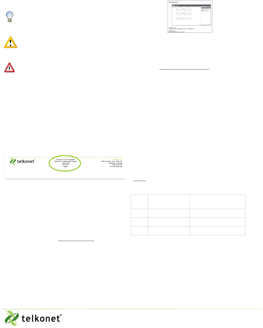
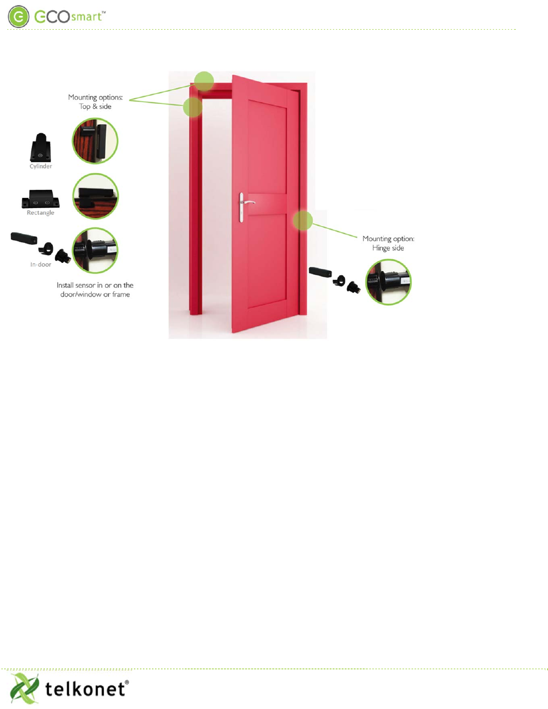
Components
The EcoContact+ consists of two components: a sensor and a magnet. One component is installed on the
door/window and the other is installed on the door/window frame, or vice versa. (In this guide, any reference
to “door” will mean “door and/or window”.)
Each EcoContact+ set includes:
1. One EcoContact+ sensor
2. One magnet (or magnet set if in-door)
Your magnet was selected during the order phase of your project, based on the door and frame design
(material, size, etc.).
1
1
Telkonet is not responsible for any door warranty that may be voided when our product is inserted in or on a door or frame.
EcoContact+ IOM Guide
Telkonet, Inc.
For Use With Firmware V. 2.x
20800 Swenson Drive, Suite 175
Anatomy of an EcoSense+
Waukesha, WI 53186
Revision
4
(800) 380-9640
Page 4
www.telkonet.com
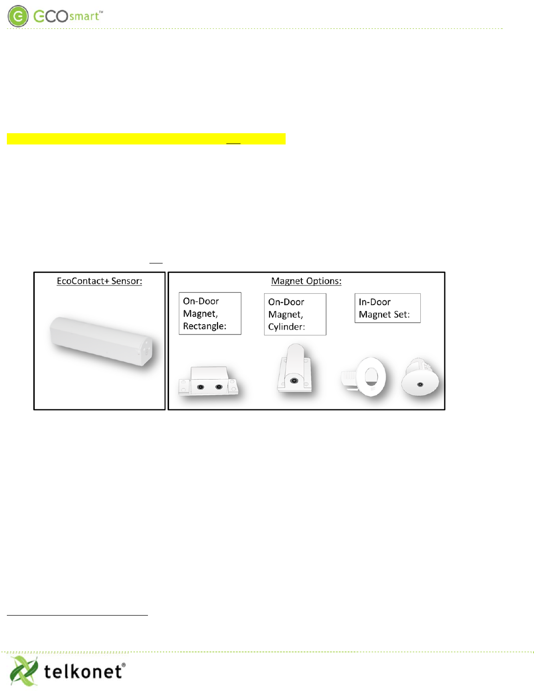
AnatomyofanEcoSense+
“Holes”inEcoContact+Sensor
Figure 1 Sensor "Holes"
Targets
When installed, the magnet “target” must be aligned with the sensor target. For example:
The EcoContact+ sensor and the rectangle magnet each contains 2 targets (for additional placement options).
Rectangular surface magnet and sensor each has 2 targets, for additional configuration options.
EcoContact+ IOM Guide
Telkonet, Inc.
For Use With Firmware V. 2.x
20800 Swenson Drive, Suite 175
Anatomy of an EcoSense+
Waukesha, WI 53186
Revision
4
(800) 380-9640
Page 5
www.telkonet.com
Placement
EcoContact+ IOM Guide
Telkonet, Inc.
For Use With Firmware V. 2.x
20800 Swenson Drive, Suite 175
Anatomy of an EcoSense+
Waukesha, WI 53186
Revision
4
(800) 380-9640
Page 6
www.telkonet.com
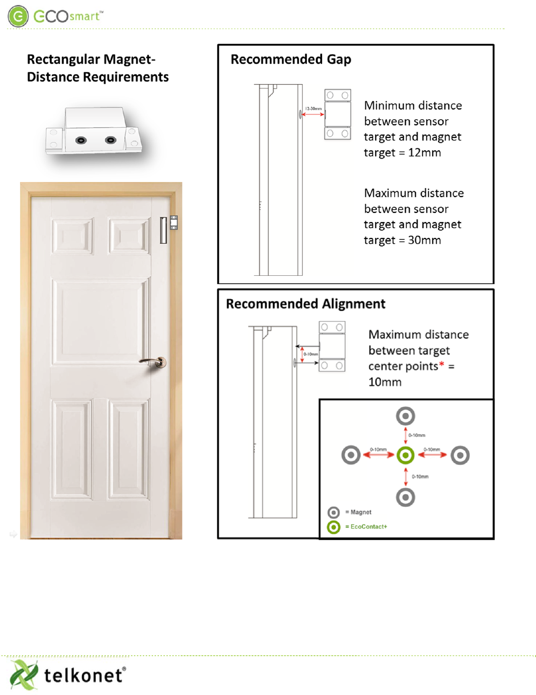
* If the distance exceeds 10mm in any direction, shimming may be required to ensure proper alignment of
center points.
EcoContact+ IOM Guide
Telkonet, Inc.
For Use With Firmware V. 2.x
20800 Swenson Drive, Suite 175
Anatomy of an EcoSense+
Waukesha, WI 53186
Revision
4
(800) 380-9640
Page 7
www.telkonet.com
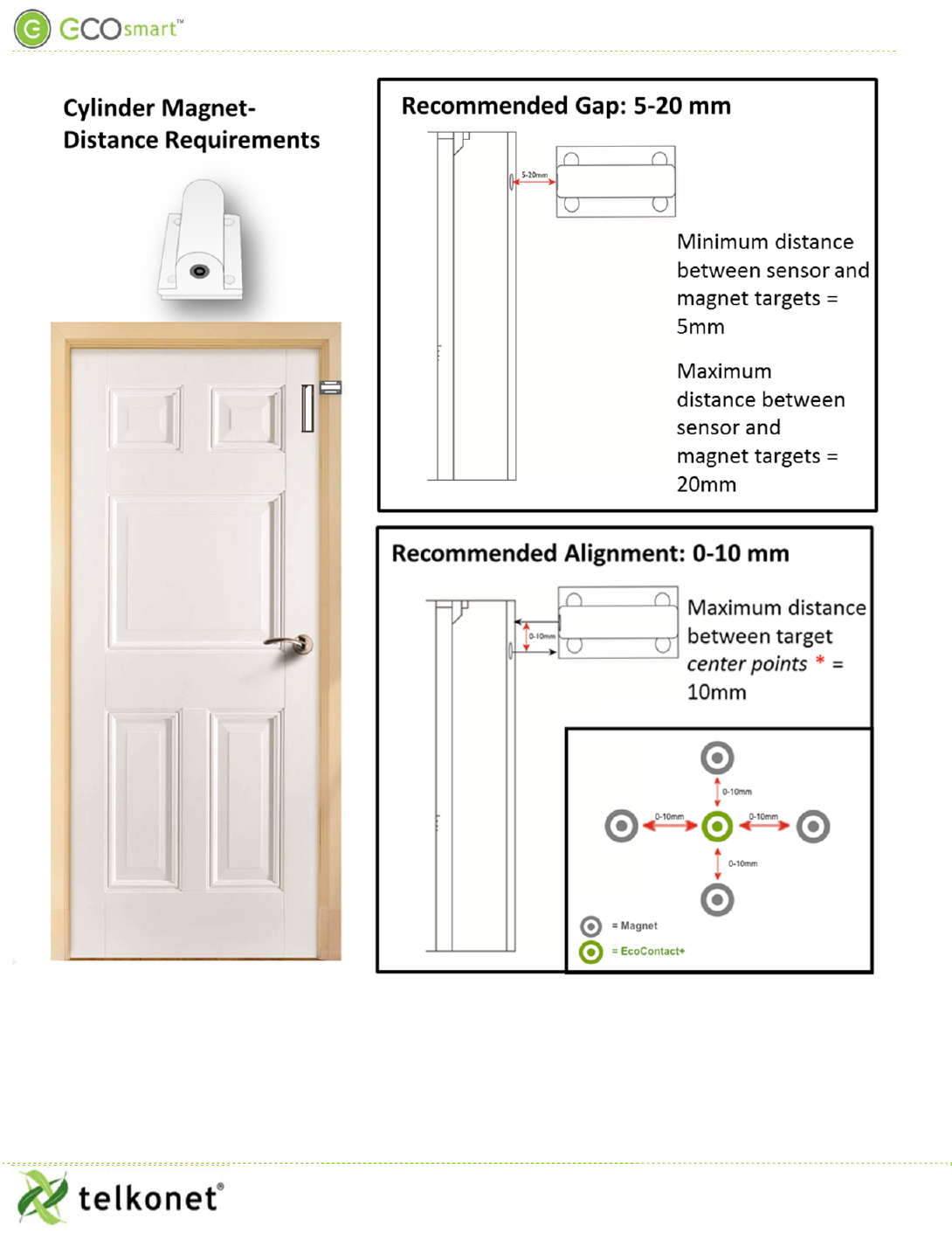
* If the distance exceeds 10mm in any direction, shimming may be required to ensure proper alignment of
center points.
EcoContact+ IOM Guide
Telkonet, Inc.
For Use With Firmware V. 2.x
20800 Swenson Drive, Suite 175
Anatomy of an EcoSense+
Waukesha, WI 53186
Revision
4
(800) 380-9640
Page 8
www.telkonet.com
Magnet Type: Minimum distance
between target on
magnet and target
on sensor:
Maximum
distance between
target on magnet and target on
sensor:
Distance between target
center points
In-door magnet 0mm
30mm (if magnet is installed in a
metal door frame, this distance is
reduced)
0-10mm
On-door cylinder
magnet 5mm 20mm
0-10mm
On-door rectangular
magnet 12mm
30mm
0-10mm
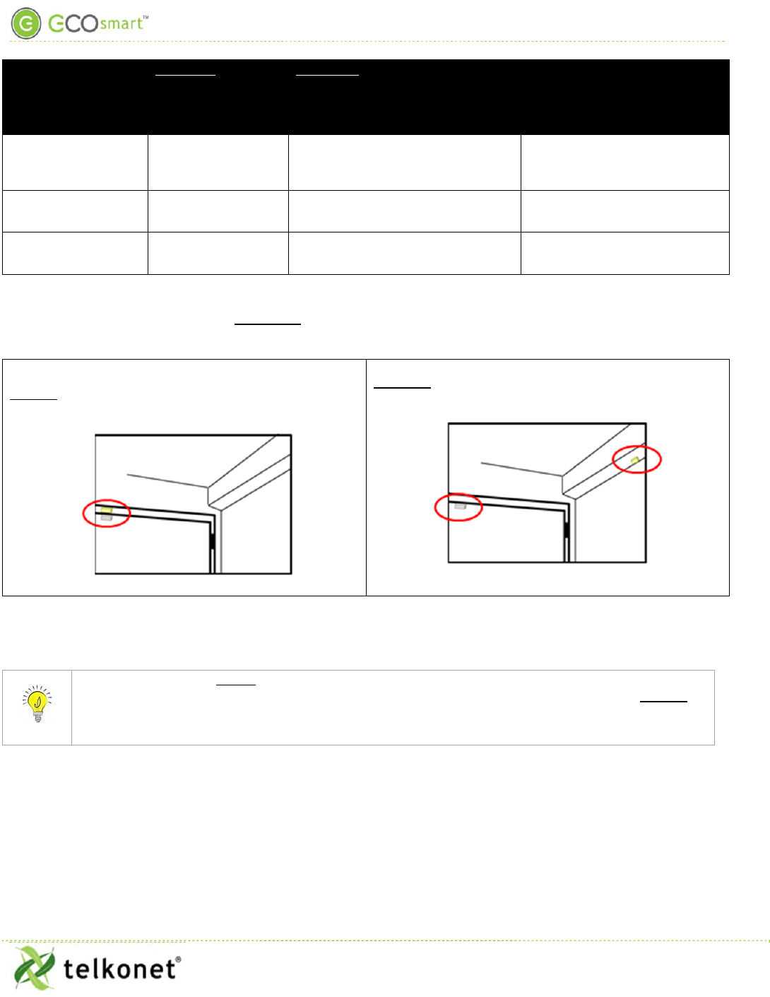
SpecialConsiderationsforIn‐DoorMountingPlacement
DoThis,NotThat
Correct- sensor and magnet are within the maximum
distance when the door is closed:
Incorrect-door would have to swing all the way open
in order for the sensor to read the magnet:
Sensor:Doorvs.Frame
Consider this: If your sensor is drilled into the door, and at some later date the door gets
replaced, you risk losing the sensor. In that scenario, it is worth considering drilling the magnet
into the door instead of drilling the sensor into the door. The magnet is less expensive to replace
than the sensor.
EcoContact+ IOM Guide
Telkonet, Inc.
For Use With Firmware V. 2.x
20800 Swenson Drive, Suite 175
Installation Procedures
Waukesha, WI 53186
Revision
4
(800) 380-9640
Page 9
www.telkonet.com
WordofCautionaboutIn‐DoorMountinginMetalDoors/Frames
If your door/window or frame is constructed of metal, do NOT install the EcoContact sensor in it. Metal will
interfere with wireless signal.
The magnet, however, CAN be installed in a metal door/window or frame.
Component: Install in
metal? Install in non-metal (e.g. fiberglass, wood)?
EcoContact+ sensor NO Yes
EcoContact+ in-door magnet Yes Yes
InstallationProcedures
RequiredEquipment
On-Door Mount: In-Door Mount:
AAA Battery AAA Batter
y
1 Sensor 1 Senso
r
1 Magnet 1 Magnet Set
Adhesive strip Drill with Forstner drill bit
InstallAAABatteryinSensor
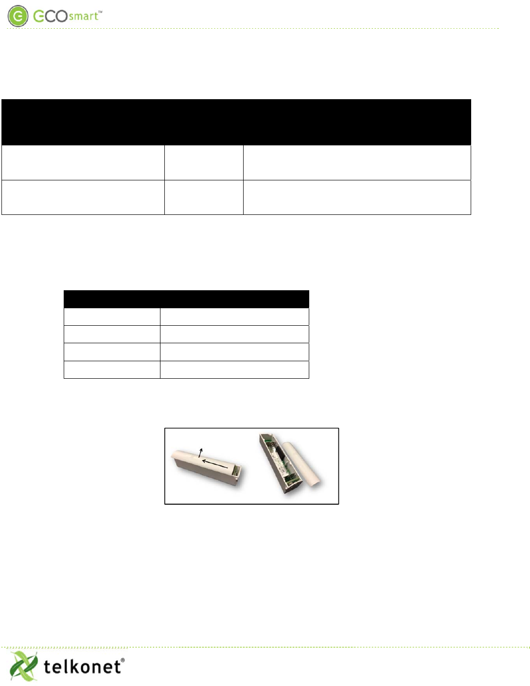
Step 1 Slide sensor cover away from the “target’ end of the sensor, and lift off the cover:
Figure 2 Remove Cover
Step 2 Install the AAA battery.
Step 3 Replace the cover.
IdentifyTargetSensortobeUsed
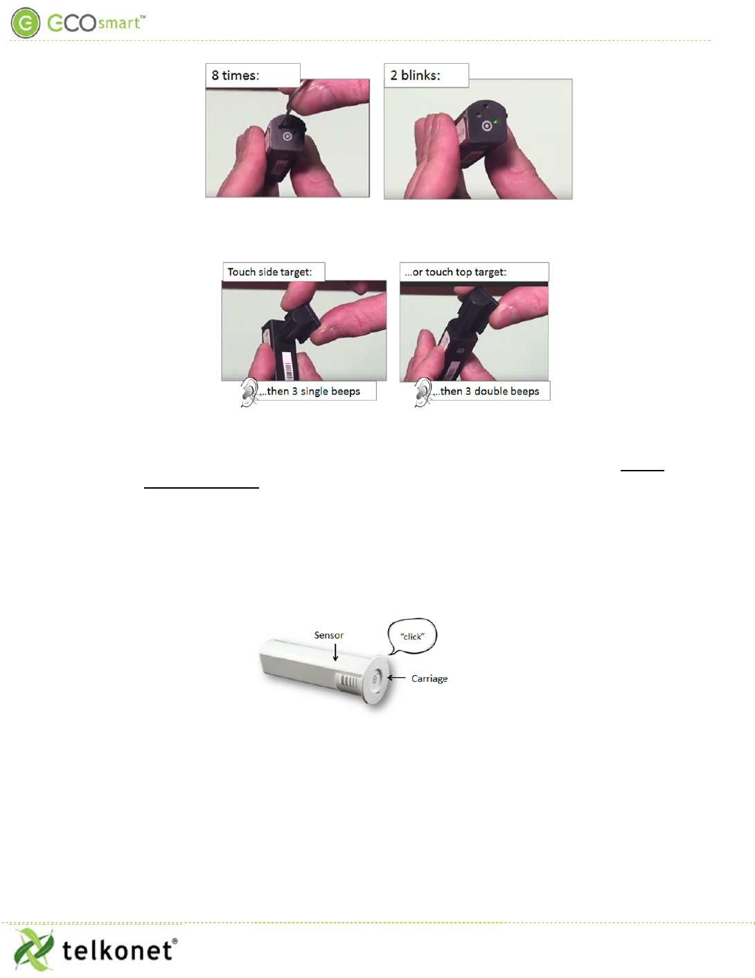
Step 4 Using the straight end of the extractor tool, press the EcoContact+ sensor button 8 times.
The LED will blink twice:
EcoContact+ IOM Guide
Telkonet, Inc.
For Use With Firmware V. 2.x
20800 Swenson Drive, Suite 175
Installation Procedures
Waukesha, WI 53186
Revision
4
(800) 380-9640
Page 10
www.telkonet.com
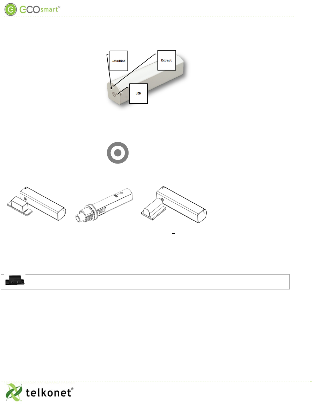
Step 5 Touch the sensor’s target to the magnet’s target. Release when you hear 3 single beeps
(side target) or 3 double beeps (top target):
Join/Bind
Step 6 Join your EcoContact+ to the network and bind it with the thermostat. (See Device
Association Guide for instructions.)
Step 7 Continue with either In-Door Mounting Option (next) or On-Door Mounting Option (page
11).
In‐DoorMountingOption
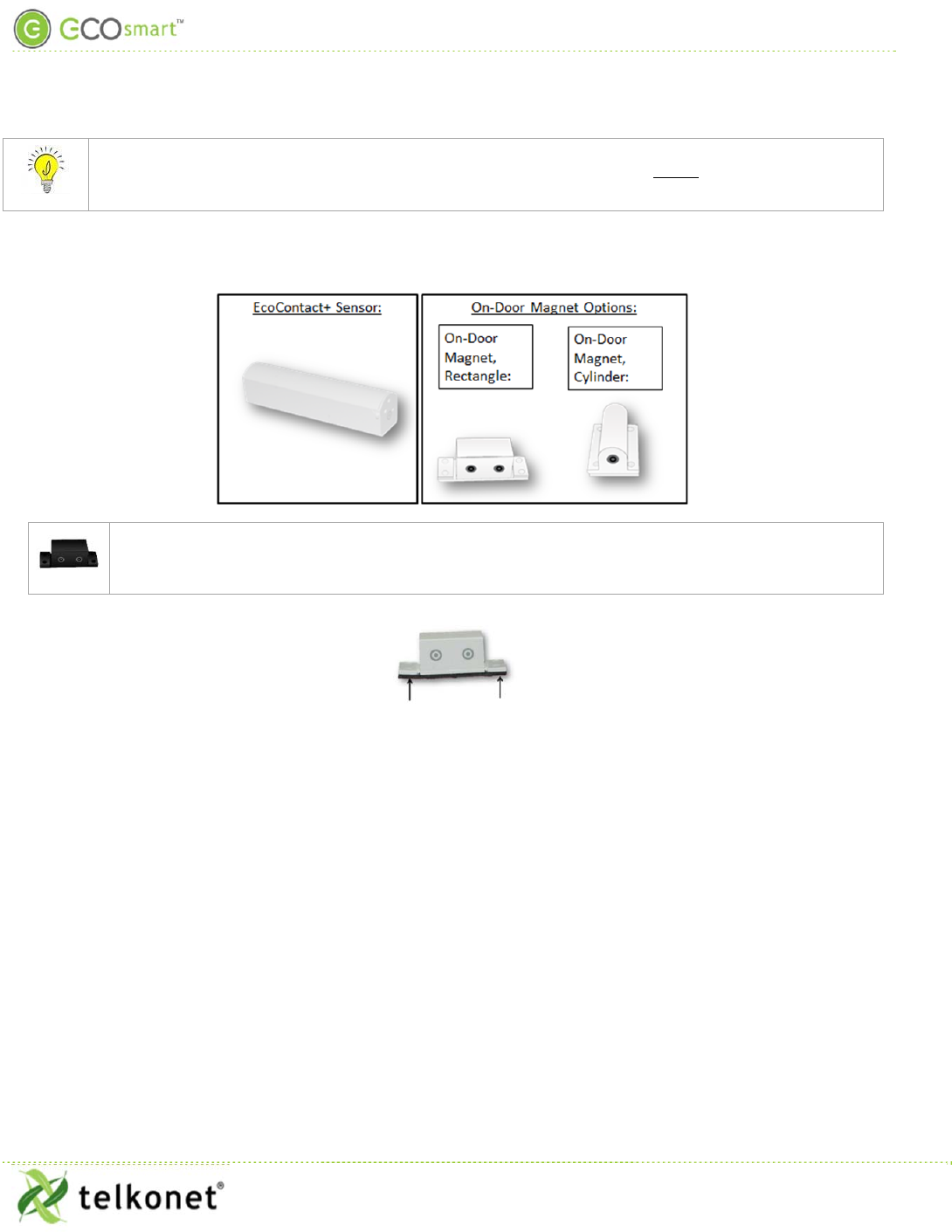
Step 8 Connect sensor and carriage as shown here. You will hear a click:
Figure 3 Connect Carriage to Sensor
Step 9 Determine the best sensor and magnet locations, so that the targets are aligned when the
door is closed, and the maximum distance between interior mount magnet and sensor
when door/window is closed is 25mm.
Step 10 Mark the installation locations on the door and frame.
Step 11 Drill 7/8” hole for sensor/attached carriage.
EcoContact+ IOM Guide
Telkonet, Inc.
For Use With Firmware V. 2.x
20800 Swenson Drive, Suite 175
Installation Procedures
Waukesha, WI 53186
Revision
4
(800) 380-9640
Page 11
www.telkonet.com
Step 12 Drop sensor with attached carriage into the door so that it is flush with the door edge.
Step 13 Drill a 7/8” hole in the frame and insert the magnet, target side out, into the door frame.
Reminder: components can be reversed if desired: magnet can be inserted in door/window and
sensor can be inserted in frame (excludes door/window and frames of metal construction; see
“Word of Caution” on page 9).
On‐DoorMountingOption
The rectangular or cylindrical magnets are used for the exterior mount:
If your magnet is the rectangular design, you may need to remove the detachable “feet” (see
Figure 4 below) for exceptionally tight spaces, such as recessed or narrow frames. The feet
should remain attached whenever space allows.
Step 1 Determine the appropriate location to install the sensor and magnet on the door and door
frame (see page 5).
Step 2 Make sure all mounting surfaces are clean and dry.
Step 3 The sensor features 2 targets. Determine which sensor target will be aligned with the
magnet target so that the targets are aligned when the door is closed. (Rectangle magnet
also has 2 targets. Determine which magnet target will be used.
Step 4 Rectangle magnet only: Remove one or both detachable feet as space dictates
Step 5 The magnet comes with an adhesive strip already attached. Remove the protective film
and adhere the magnet to the door frame.
Step 6 For the sensor, remove the plastic film from one side of the separate adhesive strip. Affix
the adhesive strip to the appropriate side of the sensor. Remove the protective film from
other side and affix the sensor to the door/window/frame.
Figure 4 Detachable "Feet" for Exceptionally Tight Spaces
EcoContact+ IOM Guide
Telkonet, Inc.
For Use With Firmware V. 2.x
20800 Swenson Drive, Suite 175
Installation Procedures
Waukesha, WI 53186
Revision
4
(800) 380-9640
Page 12
www.telkonet.com
Step 7 Verify the magnet is facing the correct direction and is in line with the target on the
EcoContact+.
Step 8 Connect your thermostat to ESU. In ESU navigate to the Devices/Sensors tab. Verify that
the EcoContact+ listed under the EcoInsight or EcoSource. (This means it is bound to the
thermostat.)
Step 9 Also in the Devices/Sensors tab, verify that the EcoContact is communicating and sending
information packets: look for an increase of RX/TX packets on the EcoContact line.
Step 10 In the Devices/Sensors tab, Sensor Index, verify an entry for the EcoContact+, 2 entries if
you are configuring both Lanai and Occupancy.
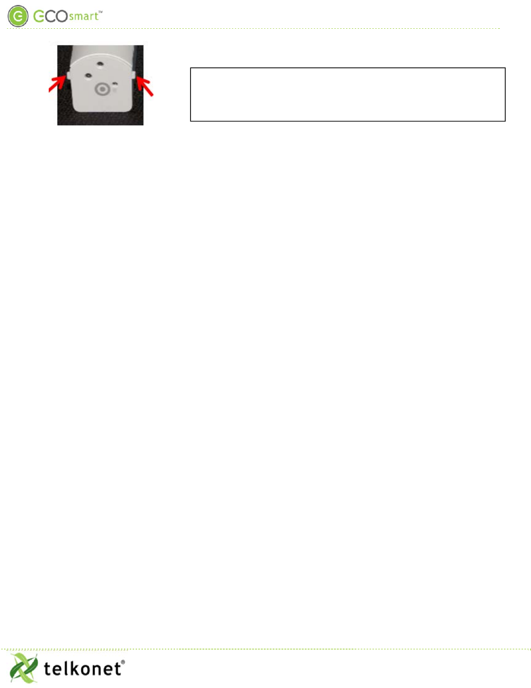
FAQ: Will these notches interfere with the mounting surface?
A: No. When the adhesive strip is affixed, the notch will not
interfere whatsoever.
EcoContact+ IOM Guide
Telkonet, Inc.
For Use With Firmware V. 2.x
20800 Swenson Drive, Suite 175
Maintenance
Waukesha, WI 53186
Revision
4
(800) 380-9640
Page 13
www.telkonet.com
Maintenance
EcoContact+ battery life is approximately 4 years.
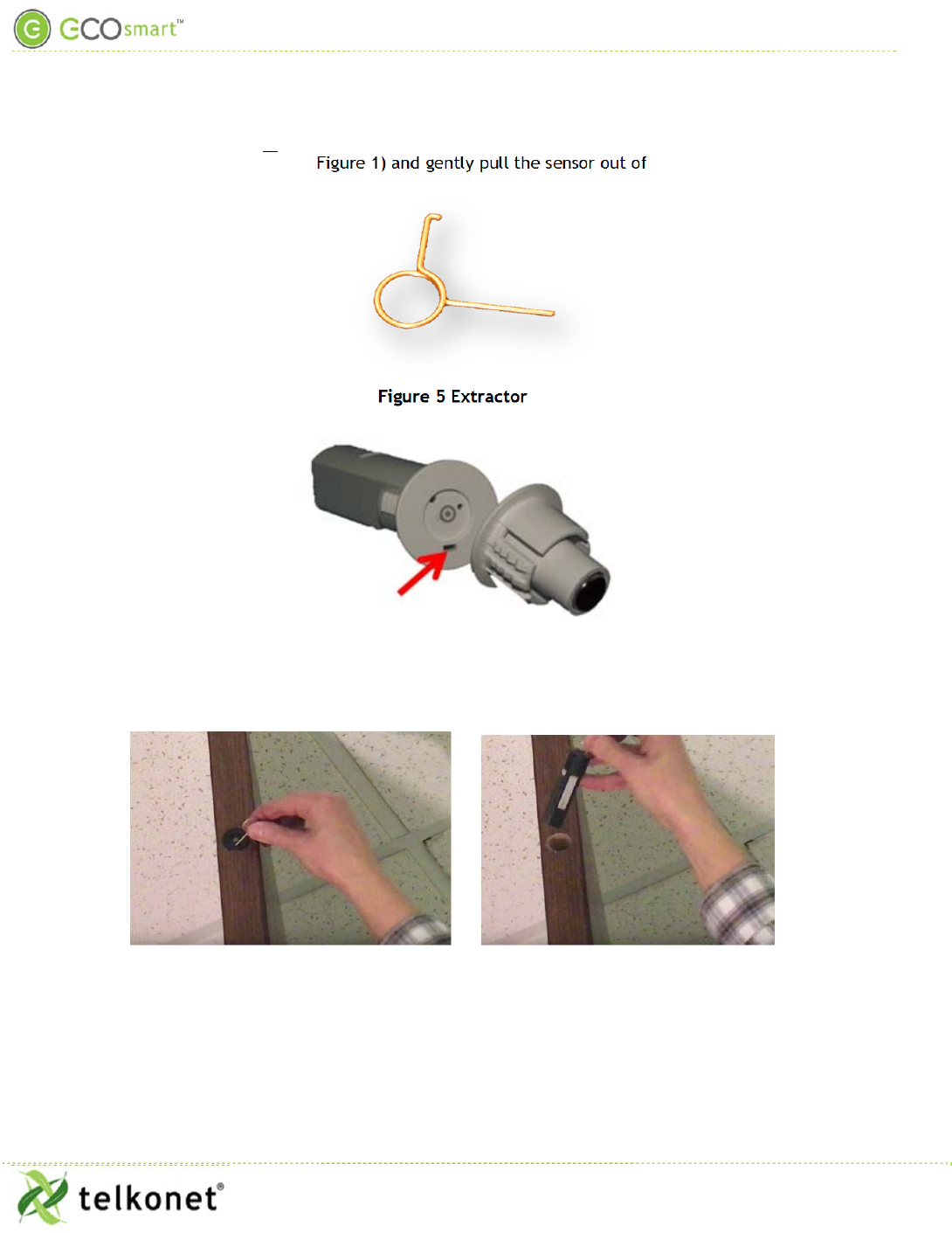
If your EcoContact+ is mounted in the door, extract the sensor from the door using the extractor (see Figure 5)
to “hook” into the extractor hole (see Figure 1) and gently pull the sensor out of the door/frame.
Figure 5 Extractor
Figure 6 Extractor Hole When Carriage is Attached
EcoContact+ IOM Guide
Telkonet, Inc.
For Use With Firmware V. 2.x
20800 Swenson Drive, Suite 175
Troubleshooting
Waukesha, WI 53186
Revision
4
(800) 380-9640
Page 14
www.telkonet.com
Troubleshooting
Problem:
The EcoContact+ does not begin communicating with the network.
Solution:
1. Ensure the battery is installed in the correct position.
2. Ensure the EcoContact is joined to the network before binding it to the thermostat.
3. When all else fails, issue a LEAVE command (12 consecutive recessed button presses) two or three
times in a row and then attempt to rejoin it to the network (see Device Association Guide for joining
instructions).
Problem:
EcoContact+ lost communication with the network.
Possible cause:
The EcoConnect Coordinator has lost power.
Solution:
1. Plug the EcoConnect to its power source.
2. Expect automatic EcoContact+ re-connection based on a specific interval attempt pattern (see table below).
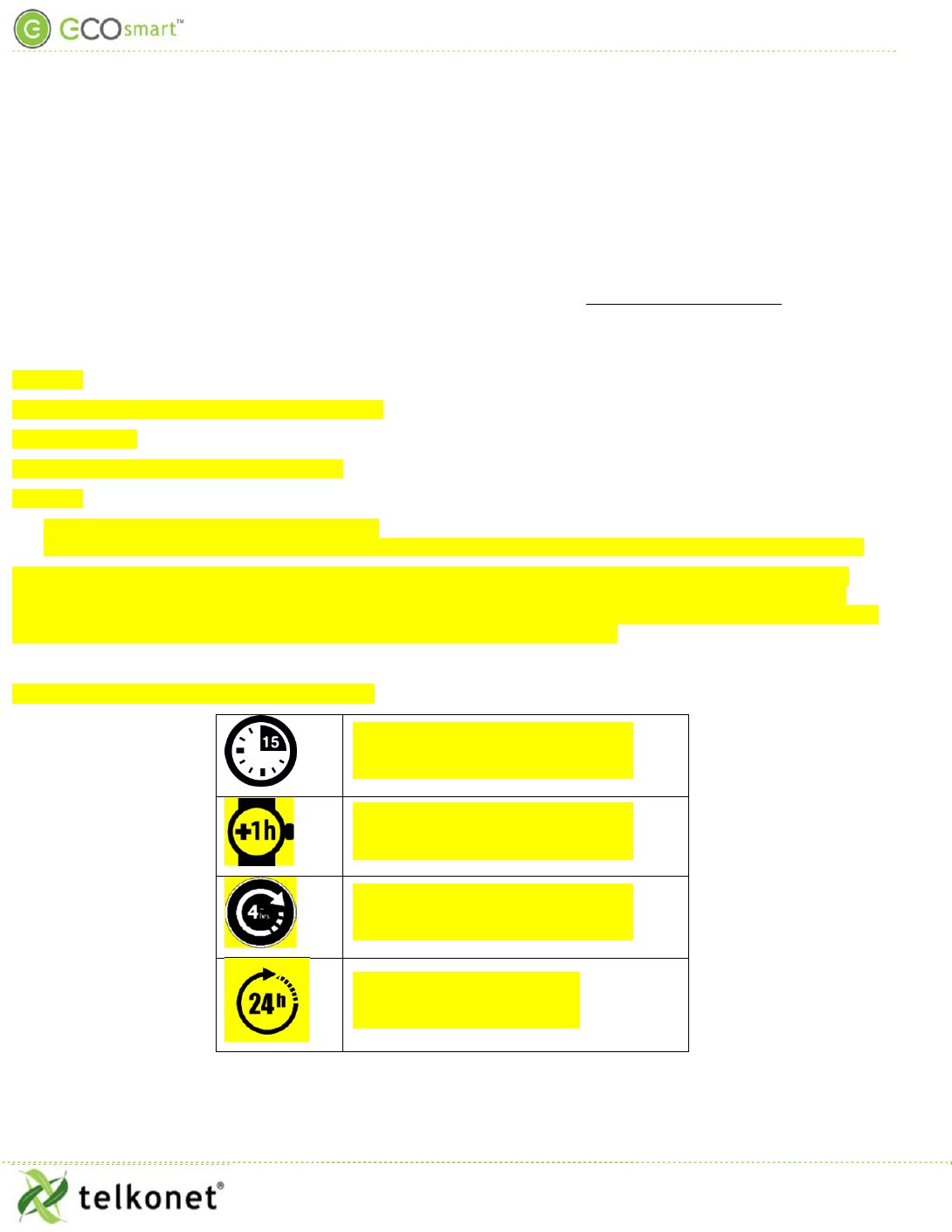
How it Works: When EcoConnect power is lost, the EcoContact+ will automatically jump into action, attempting to
reconnect to the EcoConnect at regular intervals. It will eventually reconnect to the (powered) EcoConnect, but be
mindful of the interval: the EcoContact+ will try to reconnect every 15 minutes for a total of 3 attempts, then every hour
(4 attempts), then every 4 hours (4 attempts) and once every 24 hours thereafter.
Network Re-Connection Pattern and Timing:
X 3 attempts
X 4 attempts
X 4 attempts
thereafter