Teltronic U PTBSR75760B BSR75 Digital RF transceiver User Manual User and Installation Manual
Teltronic S.A.U. BSR75 Digital RF transceiver User and Installation Manual
Contents
- 1. User manual
- 2. 10._Use Guide
User manual

BSR75 USER AND INSTALLATION MANUAL
01.01.00/1 Rev.1
PRODUCT: BSR75
CODE: D138X61PT_DDS06
VERSION: 03 REVISION: 03 DATE: 14-Sept-2016
CLASSIFICATION:
General information Internal document
DOCUMENT MAINTENANCE
THIS DOCUMENT HAS 17 PAGES
EDIT. DATE AUTHOR DESCRIPTION
1.0 15-Jul-2009 Javier Córdova First edition.
1.1 05-Aug-2010 A. Narvaiza Changes in frequency bands: 409-430 MHz
2.0 04-May-2012 Javier Córdova New frequency band: 763-806 MHz.
Code and minor editorial changes.
Changes in section 4.
3.0 13-Nov-2012 A. González Addition of labelling information.
3.1 19-Dec-2012 A. González FCC RF Exposure Requirements updating.
3.2 28-Jul-2016 C. Casanova Disclaimer updated
Removed 50 ohms load
Nominal voltage to 27.4 Volts
3.3 14-Sept-2016 C. Casanova Changes in equipment label
3.4 27-Sept-2016 C. Casanova Changes in section 5 and 10
DOCUMENT APPROVAL
ACTIVITY NAME DATE SIGNATURE
Prepared
Revised
Project Manager
Approved
R&D Director

BSR75 USER AND
INSTALLATION
MANUAL
Code: D138X61PT_DDS06
Date: 14-09-16 Page: 2 of 21
01.01.00/1 Rev.1
PowerTrunk Inc. is the subsidiary of Teltronic S.A.U. responsible for business development, distribution and
customer support for Teltronic’s Land Mobile Radio products in North America. The company is headquartered in
New Jersey. Teltronic S.A.U. distributes the same products for Land Mobile Radio under different trademarks
and brand names in other regions of the world.
Disclaimer
Although every reasonable effort has been made to ensure the accuracy of the information contained herein and
in any other referred document, this should not be construed as a commitment on the part of Teltronic S.A.U.
and/or PowerTrunk Inc., and the liability of Teltronic S.A.U. and/or PowerTrunk Inc. for any errors and omissions
shall be limited to the correction of such errors and omissions. Teltronic S.A.U. and/or PowerTrunk Inc.
welcomes any comment as a way to improve any delivered documentation.
The information contained herein has been prepared for the use of appropriately trained personnel, and it is
intended for the purpose of the agreement under which the information is submitted. Any party using or relying
upon this information assumes full responsibility for such use and in no event shall Teltronic S.A.U. and/or
PowerTrunk Inc. be liable to anyone for special, collateral, incidental, or consequential damages in connection
with or arising out of the use of this information.
The information or statements given in these documents regarding the suitability, capacity or performance of the
mentioned hardware or software products cannot be considered binding but shall be defined in the agreement
made between Teltronic S.A.U. and/or PowerTrunk Inc. and the customer.
Teltronic S.A.U. and/or PowerTrunk Inc. reserves the right to revise these documents and to make changes to
their content at any time without prior notification.
Copyright
No part of the information contained herein and in the other referred documents may be copied, distributed or
transmitted by any means to any other party without prior written permission of Teltronic S.A.U. and/or
PowerTrunk Inc. The distribution of this document may be also covered by NDA (non-disclosure agreement)
between Teltronic S.A.U. and/or PowerTrunk Inc. and the receiver.
Please also note that part of these contents even may be covered by patent rights.
This document, the referred documents and the described product are considered protected by copyright
according to the applicable laws.
PowerTrunk and the PowerTrunk logo are registered trademarks of Teltronic S.A.U.
Copyright © PowerTrunk Inc. All rights reserved.

BSR75 USER AND
INSTALLATION
MANUAL
Code: D138X61PT_DDS06
Date: 14-09-16 Page: 3 of 21
01.01.00/1 Rev.1
CONTENTS:
1. INTRODUCTION ......................................................................................................... 4
2. UNPACKING AND CHECKING .................................................................................. 5
3. PREVIOUS CONSIDERATIONS................................................................................. 5
4. LABELLING AND INFORMATION ON SAFETY AND ELECTROMAGNETIC
COMPATIBILITY ........................................................................................................ 5
5. FCC RF EXPOSURE REQUIREMENTS: .................................................................... 6
6. EQUIPMENT DESCRIPTION ...................................................................................... 8
6.1. FRONT VIEW .......................................................................................................... 8
6.2. REAR VIEW ............................................................................................................ 9
6.3. MODULES ............................................................................................................. 10
7. INSTALLATION GUIDE ............................................................................................ 13
7.1. LOCATION ............................................................................................................ 13
7.2. POWER SUPPLY CONNECTION ......................................................................... 13
10. ANNEXE MANUEL D’UTILISATEUR ET D’INSTALLATION DE LA BSR75 .......... 18

BSR75 USER AND
INSTALLATION
MANUAL
Code: D138X61PT_DDS06
Date: 14-09-16 Page: 4 of 21
01.01.00/1 Rev.1
1. INTRODUCTION
The BSR75 is a digital RF transceiver with a transmitter output power of 75 W. It is
manufactured following a robust mechanical modular design which allows simple and
economic maintenance.
The BSR75 is available in the following frequency bands:
q380 - 400 MHz
q409 - 430 MHz
q450 - 470 MHz
q763 - 806 MHz (*1)
q806 - 870 MHz (*2)
(*1) Note: For Industry Canada, the frequency range is 768-776 MHz and 798-806 MHz.
For FCC, the frequency range is 769-775 MHz and 799-805 MHz.
(*2) Note: For Industry Canada, the frequency range is 806-824 MHz and 851-869 MHz.
For FCC, the frequency range is 809-824 MHz and 854-869 MHz.
Frequency configuration is only allowed and controlled directly by the grantee
(TELTRONIC, S.A.U.).
The modules that form the BSR75 are:
qRPS75 (Repeater Power Supply)
qRPA75 (Repeater Power Amplifier)
qRTX75 (Repeater Transmitter)
qRRX (Repeater Receiver)
qBSYNC (BSR75 Synchronism) - OPTIONAL
qRCPU (Repeater Control Processing Unit)
The proper operation of any electronic device depends on its correct use. It is
therefore recommended to follow the instructions in this manual.
!
CAUTION: Switch the BSR75 off before inserting/removing any of its modules.
BSR75 USER AND
INSTALLATION
MANUAL
Code: D138X61PT_DDS06
Date: 14-09-16 Page: 5 of 21
01.01.00/1 Rev.1
2. UNPACKING AND CHECKING
The following elements are supplied in the box:
BSR75
Power Supply Cable
Maintenance Cable
Two Ethernet Cables
The equipment is supplied with all the modules already assembled in the rack. The
modules in the basic configuration are: Power Supply module (RPS), Power Amplifier
(RPA75), Transmitter (RTX75), Receiver (RRX) and Control (RCPU). Synchronism
module (BSYNC) is necessary for testing purposes.
IMPORTANT: if any of these elements is missing or damaged, contact your dealer
and / or installer.
3. PREVIOUS CONSIDERATIONS
This manual contains information on instructions for installation, maintenance and
use. Read the following pages before using this equipment.
Do not switch on the BSR75 without having previously connected the TX antenna.
The equipment may be seriously damaged. It is important to use an antenna adjusted to
the BSR75 transmitter frequency band.
4. LABELLING AND INFORMATION ON SAFETY AND ELECTROMAGNETIC
COMPATIBILITY
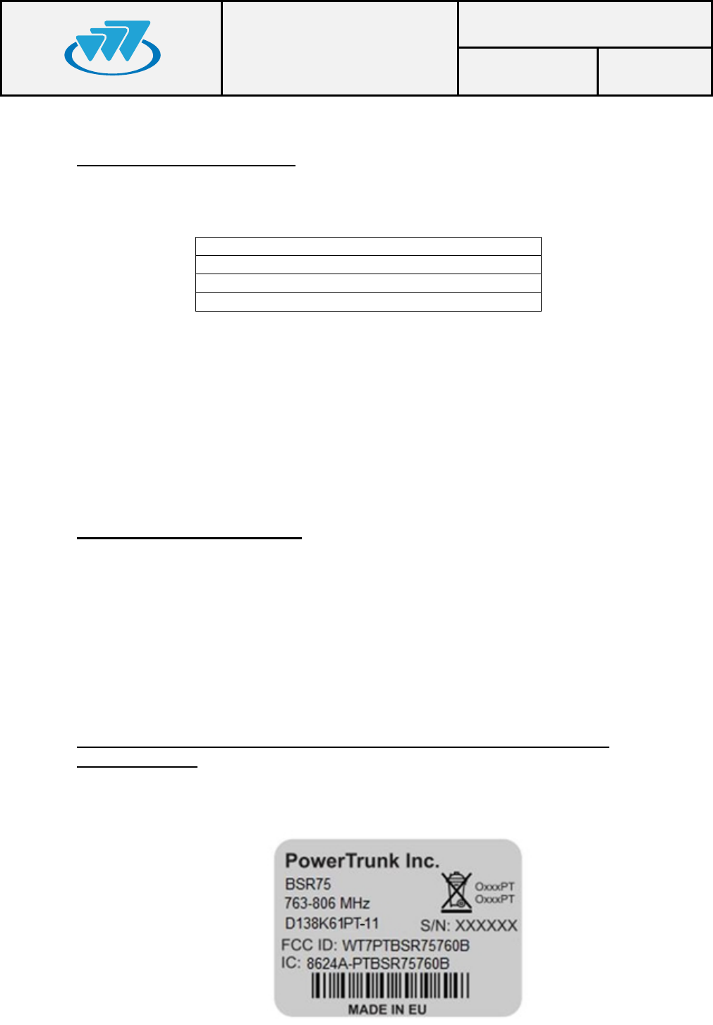
The equipment is supplied with an identification label where the model, the IC
Certificate number and the FCC ID are displayed depending on the frequency work band.
BSR75 USER AND
INSTALLATION
MANUAL
Code: D138X61PT_DDS06
Date: 14-09-16 Page: 6 of 21
01.01.00/1 Rev.1
The equipment has been designed to fulfil the applicable compliance regulations.
The equipment complies with the applicable Parts of the FCC Title 47 of the Code
of Federal Regulations and Industry Canada (IC) RSS-119 Standard.
This device complies with part 15 of the FCC Rules and Industry Canada ICES-
003. Operation is subject to the following two conditions: (1) this device may not cause
interference, and (2) this device must accept any interference, including interference that
may cause undesired operation of the device.
Changes or modifications not expressly approved by the party responsible for
compliance could void the user's authority to operate the equipment
5. FCC RF EXPOSURE REQUIREMENTS:
CAUTION:
The antenna(s) used for this transmitter must not be co-located or operating in
conjunction with any other antenna or transmitter.
Antennas used for this transmitter must not exceed an antenna gain of 20 dBi and
be located at least 525 cm, away from any person(s) in order to comply with the FCC RF
exposure requirements.
Failure to observe these restrictions will result in exceeding the FCC RF exposure
limits.
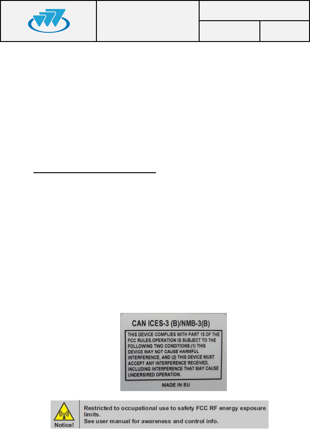
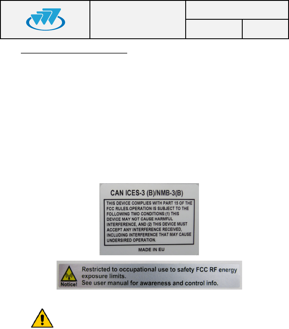
The following labels will be placed in conspicuous view on the BSR75 depending
on the frequency work band of the equipment:

BSR75 USER AND
INSTALLATION
MANUAL
Code: D138X61PT_DDS06
Date: 14-09-16 Page: 7 of 21
01.01.00/1 Rev.1
In any case, take the following points into consideration:
qMost electronic equipments are susceptible to electromagnetic interference if
they are not duly protected. If the BSR75 is placed near unprotected
electronic devices, they may malfunction.
qThe BSR75 must not transmit without its antenna connected.
qWhen installing the antenna, follow the guidelines for exposure of the human
body to high and low frequency electromagnetic fields. Follow the supplier’s /
manufacturer’s instructions.
qBurns may be suffered if the antenna connector output of the power module
(RPA75) is touched by bare skin when the BSR75 is transmitting with the
antenna disconnected.
qTake care when handling the BSR75. It has sharp edges, which may cut if
handled incorrectly.
qMaintenance and repair of these repeaters must be carried out by qualified
personnel only.
qConnect the BSR75 chassis to the earth intake in the cabinet where it is to be
installed.
qSwitch off the BSR75 before inserting/removing any of its modules
!
BSR75 USER AND
INSTALLATION
MANUAL
Code: D138X61PT_DDS06
Date: 14-09-16 Page: 8 of 21
01.01.00/1 Rev.1
6. EQUIPMENT DESCRIPTION
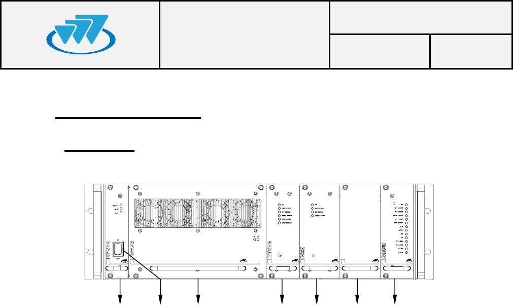
6.1.FRONT VIEW
1.- RPS (Repeater Power Supply).
2.- RPA75 (Repeater Power Amplifier).
3.- RTX75 (Repeater Transmitter).
4.- RRX (Repeater Receiver).
5.- BSYNC (BSR75 Synchronism) - OPTIONAL
6.- RCPU (Repeater Control Processing Unit).
7.- Power Supply switch.
7
1 2 34 5 6
BSR75 USER AND
INSTALLATION
MANUAL
Code: D138X61PT_DDS06
Date: 14-09-16 Page: 9 of 21
01.01.00/1 Rev.1
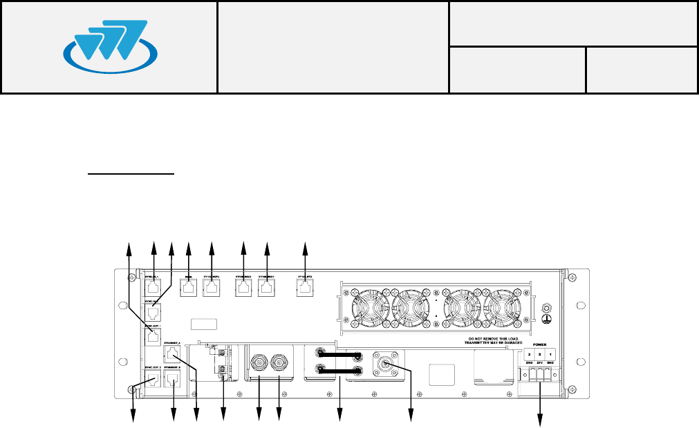
6.2.REAR VIEW
8.- Power Supply Connector.
9.- TX Antenna Connector (type N).
10.- RF cables between RTX75 and RPA75.
11.- RX Antenna Connector (type BNC).
12.- RX Diversity Antenna Connector (not used).
13.- BSYNC Connectors (not used).
14.- Ethernet Connector “ETHERNET_A”.
15.- Ethernet Connector “ETHERNET_B”.
16.- Synchronism Output Connector “SYNC_OUT_2”.
17.- Synchronism Output Connector “SYNC_OUT_1”.
18.- Synchronism Input Connector “SYNC_IN_1”.
19.- Synchronism Input Connector “SYNC_IN_2”.
20.- Bus BSR maintenance connector.
21.- RCPU maintenance connector (VT-100).
22.- RRX2 maintenance connector (Not used).
23.- RRX maintenance connector (VT-100).
24.- RTX75 maintenance connector (VT-100).
24
23
22
21
20
19
18
17
16
15
14
9
10
11
12
13
8

BSR75 USER AND
INSTALLATION
MANUAL
Code: D138X61PT_DDS06
Date: 14-09-16 Page: 10 of 21
01.01.00/1 Rev.1
6.3.MODULES
1.- RPS75 (REPEATER POWER SUPPLY)
LEDs to indicate module status.
LED TYPE NORMAL
STATUS FUNCTIÓN
SUPPLY Green On There are 27.4V at the RPS75
input
26.4V Green On There are 27.4V at the RPS75
output
13.2V Green On There are 13.2V at the RPS75
output
Power Supply switch (Ref. 7): ON/OFF switch to connect to and disconnect from the
BSR75.
2.- RPA75 (REPEATER POWER AMPLIFIER)
LEDs to indicate module status.
LED TYPE NORMAL
STATUS FUNCTIÓN
ON Green On Power supply correct
TX POWER Green On Module transmitting
3.- RTX75 (REPEATER TRANSMITTER)
LEDs to indicate module status.
LED TYPE NORMAL
STATUS FUNCTIÓN
ON Green On Power supply correct
REF. ERROR Red Off Failure in the 10 MHz reference
INT. ERROR Red Off Internal failure
BBSR ERROR Red Off Communication failure with the
RCPU module
RPA ERROR Red Off RPA75 failure
RPW ERROR Red Off Reflected power failure
BSR75 USER AND
INSTALLATION
MANUAL
Code: D138X61PT_DDS06
Date: 14-09-16 Page: 11 of 21
01.01.00/1 Rev.1
4.- RRX (REPEATER RECEIVER)
LEDs to indicate module status.
LED
TYPE
NORMAL STATUS
FUNCTIÓN
ON Green On Power supply correct
REF. ERROR Red Off Failure in the 10 MHz reference
INT. ERROR Red Off Internal failure
BBSR ERROR Red Off Communication failure with the RCPU
module
5.- SLOT OPTION: BSYNC (BSR75 SYNCHRONISM)
LEDs to indicate the status of option BSYNC.
LED
TYPE
NORMAL STATUS
FUNCTIÓN
ON Green On Power supply correct
REF. ERROR Red Off Failure in the 10 MHz reference
WARM UP Red Off Oscillator in warming up phase
TIME GPS Green Flashing There is NMEA signal from GPS
PPS GPS Green Flashing There is PPS signal from GPS
TIME LOCAL Green Flashing There is NMEA local signal (without GPS)
PPS LOCAL Green Flashing There is PPS local signal (without GPS)
NOTE: this slot is not used in the BSR75 basic configuration.

BSR75 USER AND
INSTALLATION
MANUAL
Code: D138X61PT_DDS06
Date: 14-09-16 Page: 12 of 21
01.01.00/1 Rev.1
6.- RCPU (REPEATER CONTROL)
LEDs to indicate the module status.
LED
TYPE
NORMAL STATUS
FUNCTIÓN
ON Green On Power supply correct
REF. ERROR Red Off Failure in the 10 MHz reference
INT. ERROR Red Off Internal failure
BBSR ERROR Red Off BSR75 bus failure
DIV ERROR Red Off Diversity failure
CNC ERROR Red Off Communication failure with the Site
Controller
AUX Green Off Not used
MCCH Green Off / On Main carrier indicator
RX Green Flickering Information received
TX Green On Information transmitted
ETH LINK1 Yellow On Link between the local network switch and
the RCPU module in Ethernet port 1
ETH LINK2 Yellow Off Link between the local network switch and
the RCPU module in Ethernet port 1
ETH RX Green Flashing Reception of an Ethernet packet
ETH TX Green Flashing Transmission of an Ethernet packet
BSR75 USER AND
INSTALLATION
MANUAL
Code: D138X61PT_DDS06
Date: 14-09-16 Page: 13 of 21
01.01.00/1 Rev.1
7. INSTALLATION GUIDE
The following recommendations must be followed closely before starting up the
BSR75 module.
7.1.LOCATION
The BSR75 has been designed in the standard format of 19” / 3 units high and it
must be installed in cabinets with this format.
The BSR75 site must be permanent, well-ventilated and without vibrations.
7.2.POWER SUPPLY CONNECTION
DC power supply: check that the power supply source and/or the battery to be
used meets the voltage and current requirements necessary to supply the equipment:
qNominal voltage: 27.4VDC
qMinimum source current: 20 A.
qThere is a power control circuit in the RPS75 module in order to avoid an over-
current condition.
qIf lead batteries are used, they are to be placed as far from the BSR75 as
possible to prevent corrosion in the repeater due to battery vapours. They
should be situated in a well-ventilated place.
qUse the power supply connector provided (D013000) to connect the BSR75 to
the power supply source. Use a cable with 2.5 mm2 minimum diameter (or
AWG-12). Ensure that the connection is made with the correct polarity.
qEnsure that the earth connection is made. Make this connection with a cable of
maximum diameter and minimum length.
NEVER use a gas or electricity conduit as an earth.
BSR75 USER AND
INSTALLATION
MANUAL
Code: D138X61PT_DDS06
Date: 14-09-16 Page: 14 of 21
01.01.00/1 Rev.1
7.3.ANTENNA CONNECTION
qChoose the most adaptable antenna for the installation. The antenna must
have an impedance of 50 ohms to the equipment transmission frequency.
Install the antenna in accordance with the manufacturer’s instructions.
qUse a coaxial cable, avoiding as much as possible large cable lengths. Cable
impedance is 50 ohms.
qMeasure the VSWR of the installation. Never accept a VSWR greater than 2.
qIf a duplexer module or a band pass filter is required, adjust them to the
working frequency before starting up.
7.4.SWITCHING ON THE BSR75
qCheck the connections between the modules.
qCheck that the power supply source is connected correctly.
qCheck that the RF SMB cables are connected correctly (see Rear View
diagram Ref. 10).
qCheck the connections of the antennas in the RPA75 and RRX modules.
qCheck that the RPS75 module LED SUPPLY is on.
qActivate the power on switch on the RPS75 module.
qCheck that the 26.4V LED and 13.2V LED on the RPS75 module are on and
check that the LEDS “ON” are switched on in the other modules.
qWait for the BSR75 to start up.
Note: See subclause 5.3 for more information on references for the different
modules and LEDs.

BSR75 USER AND
INSTALLATION
MANUAL
Code: D138X61PT_DDS06
Date: 14-09-16 Page: 15 of 21
01.01.00/1 Rev.1
8. CONFIGURATION
A BSR75 is configured via an NMS (Network Management System). To configure
the BSR75, consult the NMS manual.
9. INCIDENTS
The repeater must be repaired by authorized technical personnel only. If a
BSR75 failure occurs, the entire BSR75 must be replaced. If transmitter
module is damaged and there is not an entire BSR75 available to replace, set
RTX75 and RPA75 modules previously calibrated jointly. In last case and if is
not possible to carry out one of the two previous options, replace one of these two
modules and make the gain calibration again.
If an error or alarm occurs in the BSR75, this is indicated in the corresponding LED
for each one of the modules. The following list shows the possible failures and their
solutions.
9.1.ALARMS
Led
indication Status Failure / Solution
RPS75
SUPPLY OFF
Power supply failure. Check that the source and the
power supply cable are correctly connected. Check the
internal fuse of the RPS75. Contact Technical S
ervices if
unsolved.
26.4V OFF Power supply failure. Contact Technical services.
13.2V OFF Power supply failure. Contact Technical services.
RPA75
ON OFF Power supply failure. Contact Technical Services.
TX POWER OFF
No power transmission in the antenna. Wait for BSR75
to be started up. Check other LED indications. Contact
Technical Services if unsolved.
!

BSR75 USER AND
INSTALLATION
MANUAL
Code: D138X61PT_DDS06
Date: 14-09-16 Page: 16 of 21
01.01.00/1 Rev.1
RTX75
ON OFF Internal power supply failure. Contact Technical
services.
REF. ERROR ON Failure in the 10MHz reference. Contact Technical
services.
INT. ERROR ON Internal failure. Contact Technical services.
BBSR
ERROR ON Communication failure with the RCPU module. Check
that all the modules are correctly installed. Contact
Technical services if still unsolved.
RPA75
ERROR ON Failure in the RPA75 modules. Check that the RF SMB
cables (Ref. 10) are properly connected. Contact
Technical services if still unsolved.
RPW ERROR ON Reflected power alarm. Check that the antenna is
properly installed. Contact Technical services.
RRX
ON OFF Internal power supply failure. Contact Technical
services.
REF. ERROR ON Failure in the 10MHz reference. Contact Technical
services.
INT. ERROR ON Internal failure. Contact Technical services.
BBSR
ERROR ON Communication failure with the RCPU module. Check
that all the modules are correctly installed. Contact
Technical Services if still unsolved.
BSYNC
ON OFF Internal power supply failure. Contact Technical
services.
REF. ERROR ON Failure in the 10MHz reference. Contact Technical
services.
TIME GPS ON If GPS is activated, there is failure in the data frame.
Contact Technical Services.
PPS GPS OFF
If GPS is activated, there is failure in the PPS signal of
the GPS:
- check that the starting up period has been
exceeded (about 10 minutes after switching on)
- check the GPS antenna connection.
- check the correct positioning of the GPS
antenna, in accordance with the manufacturer’s
instructions.
Contact technical services if still unsolved.
TIME LOCAL OFF If GPS is not activated, there is failure in the local
reference data frame. Contact Technical Services.
PPS LOCAL OFF If GPS is not activated, there is failure in the local PPS
signal. Contact Technical Services.
BSR75 USER AND
INSTALLATION
MANUAL
Code: D138X61PT_DDS06
Date: 14-09-16 Page: 17 of 21
01.01.00/1 Rev.1
RCPU
ON OFF Internal power supply failure. Contact Technical
Services.
REF ERROR ON Failure in the 10MHz reference. Check that the BSYNC
module is installed or that the SYNC IN cable is correctly
connected. Contact Technical services if still unsolved.
INT ERROR ON Internal failure. Contact Technical Services.
BBSR
ERROR ON Communication failure by the BSR75 bus. Check that all
the modules are correctly installed. Contact Technical
services if still unsolved.
DIV ERROR ON
Error in diversity: occurs when the difference in received
power between received paths exceeds a level (20 dBs
by default) for a consecutive number of receptions.
These receptions on the received paths which do not
have sufficient power are not counted.
This alarm does not disappear until there are no
receptions with the sufficient power, and until the
difference of received power between received paths
does not exceed the level previously mentioned.
Check diversity configuration in the NMS.
Check that the reception antennas are correctly
installed. Contact Technical services if still unsolved.
CNC ERROR ON
Communication failure with the Site Controller. Check
the Ethernet connections.
Check that the Site Controller is working properly.
Contact Technical Services if still unsolved.
RX Continuous
ON
Interference detection.
Check the installation. Check that the work frequencies
are correct.
ETH LINK1 OFF Failure in Ethernet link 1.
Check Ethernet connection 1 and the Switch A.
ETH LINK2 OFF Failure in Ethernet link 2.
Check Ethernet connection 2 and the Switch B.
ETH RX OFF Packets are not received by Ethernet.
Check the Ethernet connections.
ETH TX OFF Packets are not sent by Ethernet.
Check the Ethernet connections.
BSR75 USER AND
INSTALLATION
MANUAL
Code: D138X61PT_DDS06
Date: 14-09-16 Page: 18 of 21
01.01.00/1 Rev.1
DÉCLARATION DE CONFORMITÉ
En tant que fabricant du produit , Teltronic S.A.U / PowerTrunk Inc. déclare que l'équipement en question
satisfait les exigences essentielles établies :
- dans l'article 5 de la directive du Conseil de l'Europe 2004/108/CE, du 15th décembre 2004
- Conseil de l'Europe 2006/95/CE, du 12th décembre 2006
Une copie de la déclaration de conformité est disponible sur le site Web www.teltronic.es ou sur simple
demande formulée auprès du service d'assistance technique de Teltronic.
10. ANNEXE MANUEL D’UTILISATEUR ET D’INSTALLATION DE LA BSR75
Responsabilité
Bien que tous les efforts aient été fournis afin de garantir la précision de l'information contenue dans le présent document et
ceux qui lui sont associés, celle-ci ne doit pas être considérée comme un engagement de la part de Teltronic S.A.U. /
PowerTrunk Inc dont la responsabilité à l'égard des éventuelles erreurs et omissions est limitée à leur correction. Teltronic
S.A.U. / PowerTrunk Inc reste à l'écoute de toute suggestion d'amélioration.
Les informations contenues dans le présent document sont destinées à être utilisées par un personnel qualifié aux fins de
l'accord selon lequel elles sont fournies. L'utilisateur de ces informations assume une totale responsabilité à l'égard de son
utilisation. L'entreprise Teltronic S.A.U. / PowerTrunk Inc n'est en aucun cas tenue responsable des dommages directs ou
indirects découlant de l'utilisation de ces dernières.
Les informations ou affirmations relatives à la justesse, à la capacité ou aux caractéristiques du logiciel ou du matériel
informatique ne sauraient être considérées comme un engagement et devront être spécifiquement définies dans l'accord
passé entre Teltronic S.A.U. / PowerTrunk Inc et le client.
Teltronic S.A.U. / PowerTrunk Inc se réserve le droit de réviser ce document et de procéder à des modifications de contenu à
tout moment et sans préavis.
Copyright
Ni l'ensemble ni une partie des informations contenues dans ce document ou documents qui lui sont associés ne peut être
copié, distribué ou transmis à des tiers par quelques moyens que ce soient sans autorisation préalable écrite de Teltronic
S.A.U. / PowerTrunk Inc La distribution de ce document peut être protégée par le NDA (accord de confidentialité) passé entre
Teltronic S.A.U. / PowerTrunk Inc et le bénéficiaire.
Les informations contenues dans certaines parties de ce document peuvent être protégées par des droits afférents à un
brevet.
Ce document, les documents associés et le produit décrit sont considérés comme étant protégés par Copyright conformément
aux lois applicables.
PowerTrunk et le logo PowerTrunk sont des marques déposées de Teltronic S.A.U.
© PowerTrunk Inc.
11.
GESTION DES DÉCHETS
L'apposition de ce symbole signifie que l'appareil doit faire l'objet d'une collecte sélective à la
fin de son cycle de vie. Ne pas déposer les produits dans des décharges municipales sans les
avoir triés.
Cet équipement peut être utilisé dans tous les États membres de l'Union
européenne après obtention de la licence administrative correspondante.

BSR75 USER AND
INSTALLATION
MANUAL
Code: D138X61PT_DDS06
Date: 14-09-16 Page: 19 of 21
01.01.00/1 Rev.1
INTRODUCTION
Ce manuel est commun à tous les modèles de l'équipement, quels qu'en soient les
options et accessoires installés.
Le fonctionnement approprié de tout équipement électronique dépend de sa bonne
manipulation. Pour ce faire, il est préconisé de suivre les instructions de ce manuel.
ÉTIQUETAGE ET INFORMATION SUR LA SÉCURITÉ ET LA COMPATIBILITE
ELECTROMAGNETIQUE
L'équipement est fourni avec une étiquette d'identification où le modèle, le numéro
IC certificat et l'ID FCC sont affichés en fonction de la bande de fréquence de travail.
L’équipement a été désigné pour respecter aux réglementations de conformité
applicables.
L’équipement est conforme aux parties de la FCC Titre 47 du Code de Fédéral
Régulations et du standard de l’Industrie du Canada (IC) CNR-119.
L’équipement est conforme à la partie 15 des règles de la FCC et de l’Industrie du
Canada NMB-003. Son fonctionnement est soumis aux deux conditions suivantes : (1) ce
dispositif ne doit pas causer d'interférences et (2) cet appareil doit accepter toute
interférence, inclus de l’interférence qui peuvent causer un mauvais fonctionnement de
l'appareil.
Les changements ou modifications non expressément approuvés par la partie
responsable de la conformité pourraient annuler l'autorité de l'utilisateur à utiliser
l’équipement.
BSR75 USER AND
INSTALLATION
MANUAL
Code: D138X61PT_DDS06
Date: 14-09-16 Page: 20 of 21
01.01.00/1 Rev.1
EXIGENCES DE L'EXPOSITION RF:
ATTENTION:
L'antenne(s) utilisée(s) pour ce transmetteur ne doit pas être co-localisées ou
fonctionner en conjonction avec aucun autre antenne ou transmetteur.
L’Antenne(s) utilisée(s) pour ce transmetteur ne doivent pas dépasser un gain
d'antenne de 20 dBi et être située à au moins 525 cm, loin de toute personne(s) afin de se
conformer aux exigences de la FCC et de l’IC .
Le non-respect de ces restrictions entraînera à dépasser les limites d'exposition
RF.
Les suivantes étiquettes seront placées dans évidence, sur laBSR75:
qLa plupart des équipements électroniques sont susceptibles d'être soumis
à des interférences électromagnétiques s'ils ne sont pas correctement
protégés. Le montage de l'unité BSR75 à proximité d'équipements
électroniques non protégés peut provoquer un dysfonctionnement de ces
derniers.
qIl convient d'éviter que l'unité BSR75 n'émette sans que l'antenne ne soit
branchée.
qPour procéder à l'installation de l'antenne, tenir compte des directives qui
contrôlent l'exposition du corps humain aux champs électromagnétiques
basse et haute fréquence. Respecter les consignes du
fournisseur/fabricant de l'antenne.
qPrendre garde aux brûlures susceptibles d'être provoquées par tout
contact entre une partie du corps et la sortie du connecteur d'antenne
lorsque l'unité BSR75 est en cours d'émission sans que l'antenne ne soit

BSR75 USER AND
INSTALLATION
MANUAL
Code: D138X61PT_DDS06
Date: 14-09-16 Page: 21 of 21
01.01.00/1 Rev.1
branchée.
qManipuler l'unité BSR75 avec soin. Cet équipement est pourvu d'arêtes
qui peuvent être à l'origine de coupures en cas de mauvaise manipulation.
qLa maintenance et la réparation de cet équipement doivent être prises en
charge par du personnel qualifié.