Teltronic U PTMBS800B RF Transceiver / Mast-Mounted Base Station User Manual 11 Draft04 FCC ISED English
Teltronic S.A.U. RF Transceiver / Mast-Mounted Base Station 11 Draft04 FCC ISED English
11._User Manual_Draft04_FCC&ISED_English
TETRA MBS UNIT. INSTALLATION GUIDE
F067646PT_2800
Page 1 of 62
en
Document
F067646PT_2800
Product
PowerTrunk-T
Date
January 2018
T
TE
EC
CH
HN
NI
IC
CA
AL
L
D
DE
ES
SC
CR
RI
IP
PT
TI
IO
ON
N
P
Po
ow
we
er
rT
Tr
ru
un
nk
k-
-T
T
T
TE
ET
TR
RA
A
M
MB
BS
S
U
UN
NI
IT
T.
.
I
IN
NS
ST
TA
AL
LL
LA
AT
TI
IO
ON
N
G
GU
UI
ID
DE
E

TETRA MBS UNIT. INSTALLATION GUIDE
F067646PT_2800
Page 2 of 62
en
DECLARATION OF CONFORMITY
Hereby, PowerTrunk Inc. declares that the radio equipment type Mast-mounted Base Station MBS Unit is in
compliance with Directive 2014/53/EU.
The full text of the EU declaration of conformity is available through the technical assistance service at the
Internet address: http://www.powertrunk.com
USE RESTRICTIONS
This radio equipment is subject to restrictions on putting into service or to requirements for authorization of
use in the following countries:
This equipment can be used in all Member States of the European Union once the corresponding
administrative license is obtained.
WASTE MANAGEMENT
The symbol means that the product must be taken to separate collection at the product end-of
life. Do not dispose of these products as unsorted municipal waste.

TETRA MBS UNIT. INSTALLATION GUIDE
F067646PT_2800
Page 3 of 62
en
PowerTrunk Inc. is the subsidiary of Teltronic S.A.U. responsible for business development, distribution and customer support for
Teltronic’s Land Mobile Radio products in North America. The company is headquartered in New Jersey. Teltronic S.A.U. distributes the
same products for Land Mobile Radio under different trademarks and brand names in other regions of the world.
Disclaimer
Although every reasonable effort has been made to ensure the accuracy of the information contained herein and in any other referred
document, this should not be construed as a commitment on the part of Teltronic S.A.U. and/or PowerTrunk Inc., and the liability of
Teltronic S.A.U. and/or PowerTrunk Inc. for any errors and omissions shall be limited to the correction of such errors and omissions.
Teltronic S.A.U. and/or PowerTrunk Inc. welcomes any comment as a way to improve any delivered documentation.
The information contained herein has been prepared for the use of appropriately trained personnel, and it is intended for the purpose of
the agreement under which the information is submitted. Any party using or relying upon this information assumes full responsibility for
such use and in no event shall Teltronic S.A.U. and/or PowerTrunk Inc. be liable to anyone for special, collateral, incidental, or
consequential damages in connection with or arising out of the use of this information.
The information or statements given in these documents regarding the suitability, capacity or performance of the mentioned hardware or
software products cannot be considered binding but shall be defined in the agreement made between Teltronic S.A.U. and/or
PowerTrunk Inc. and the customer.
Teltronic S.A.U. and/or PowerTrunk Inc. reserves the right to revise these documents and to make changes to their content at any time,
without prior notification.
Copyright
No part of the information contained herein and the other referred documents may be copied, distributed or transmitted by any means to
any other party without prior written permission of Teltronic S.A.U. and/or PowerTrunk Inc. The distribution of this document may be also
covered by NDA (non-disclosure agreement) between Teltronic S.A.U. and/or PowerTrunk Inc. and the receiver.
Please also note that part of these contents even may be covered by patent rights.
This document, the referred documents and the described product are considered protected by copyright according to the applicable
laws.
PowerTrunk and the PowerTrunk logo are registered trademarks of Teltronic S.A.U.
Copyright © PowerTrunk Inc. All rights reserved

TETRA MBS UNIT. INSTALLATION GUIDE
F067646PT_2800
Page 4 of 62
en
TABLE OF CONTENTS
1. INTRODUCTION 5
2. UNPACKING AND CHECKING 6
3. PREVIOUS CONSIDERATIONS 7
4. INFORMATION ON SAFETY AND ELECTROMAGNETIC COMPATIBILITY 8
4.1 GENERAL CONSIDERATIONS ABOUT SAFETY .................................................................................. 8
4.2 OPERATION AND EXPOSURE TO RF ENERGY ................................................................................... 9
4.3 IMPORTANT SAFETY NOTES ABOUT THE ANTENNA ...................................................................... 10
4.4 ELECTROMAGNETIC COMPATIBILITY REGULATORY INFORMATION (FCC AND IC) .................. 11
4.5 UL / SAFETY CERTIFICATIONS ........................................................................................................... 12
4.6 EMC, SAFETY AND RF EXPOSURE STANDARDS ............................................................................. 12
4.7 MECHANICAL AND ENVIRONMENTAL STANDARDS ....................................................................... 13
4.7.1 STANDARDS CENELEC ...................................................................................................................................... 13
4.7.2 STANDARDS MIL-STD 810G ............................................................................................................................... 14
5. EQUIPMENT DESCRIPTION 15
5.1 VIEW ....................................................................................................................................................... 15
5.2 CONNECTORS ...................................................................................................................................... 16
5.3 VISUAL INDICATORS ........................................................................................................................... 18
5.4 DIMENSIONS ......................................................................................................................................... 19
6. INSTALLATION GUIDE 20
6.1 NECESSARY EQUIPMENT ................................................................................................................... 21
6.2 BASIC PRE-CONFIGURATION ............................................................................................................. 23
6.3 INSTALLATION ..................................................................................................................................... 24
6.3.1 MAST/POLE INSTALLATION ............................................................................................................................... 26
6.3.1.1 MAST/POLE SELECTION 26
6.3.1.2 MAST/POLE MOUNTING INSTRUCTIONS 28
6.3.2 WALL INSTALLATION .......................................................................................................................................... 31
6.3.3 PBS ACCESSORY INSTALLATION ..................................................................................................................... 34
6.3.3.1 WORKING POSITIONS 37
6.3.4 ANTI-VANDAL KIT INSTALLATION ...................................................................................................................... 39
6.3.5 REQUIREMENTS TO CONSIDER DURING THE ANTENNA INSTALLATION ..................................................... 40
6.3.6 CONNECTIONS ................................................................................................................................................... 42
6.3.6.1 SUPPORTED CONFIGURATIONS 43
6.3.6.2 CONNECTION OF THE EXTERNAL POWER SUPPLY 53
6.3.6.3 ANTENNA CONNECTION 56
6.3.6.4 EXTERNAL ETHERNET CONNECTION 57
6.3.7 CONNECTING / DISCONNECTING THE MBS AC MAINS SUPPLY .................................................................... 58
6.3.8 CONNECTING / DISCONNECTING THE MBS FROM THE DC SUPPLY ............................................................. 59
7. START UP/CONFIGURATION/VERIFICATION 60
8. INCIDENTS 61
8.1 INTERFERENCE AT MBS UNIT ............................................................................................................ 61
8.2 OVER VOLTAGE PROTECTION ........................................................................................................... 62
TETRA MBS UNIT. INSTALLATION GUIDE
F067646PT_2800
Page 5 of 62
en
1. INTRODUCTION
The MBS Units are the outdoor modules that make up a Mast Mounted Base Station (MBS). They
are independent units that can be interconnected with each other to increase the base station capacity. A
MBS consists of a maximum of two MBS Units.
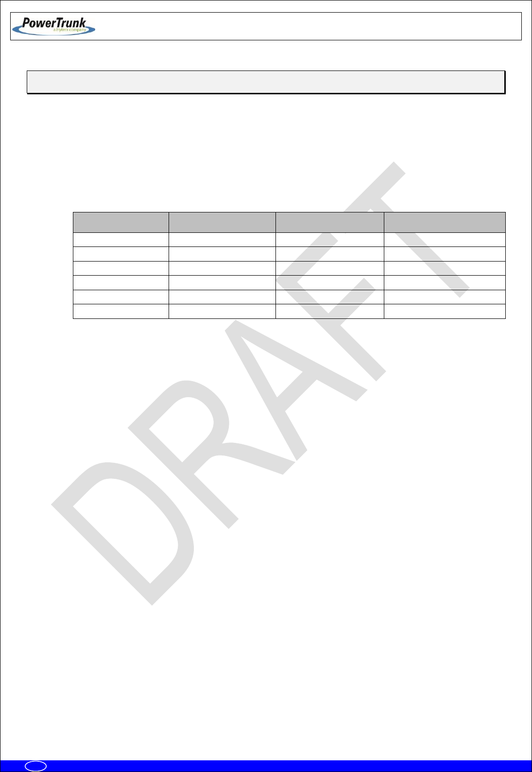
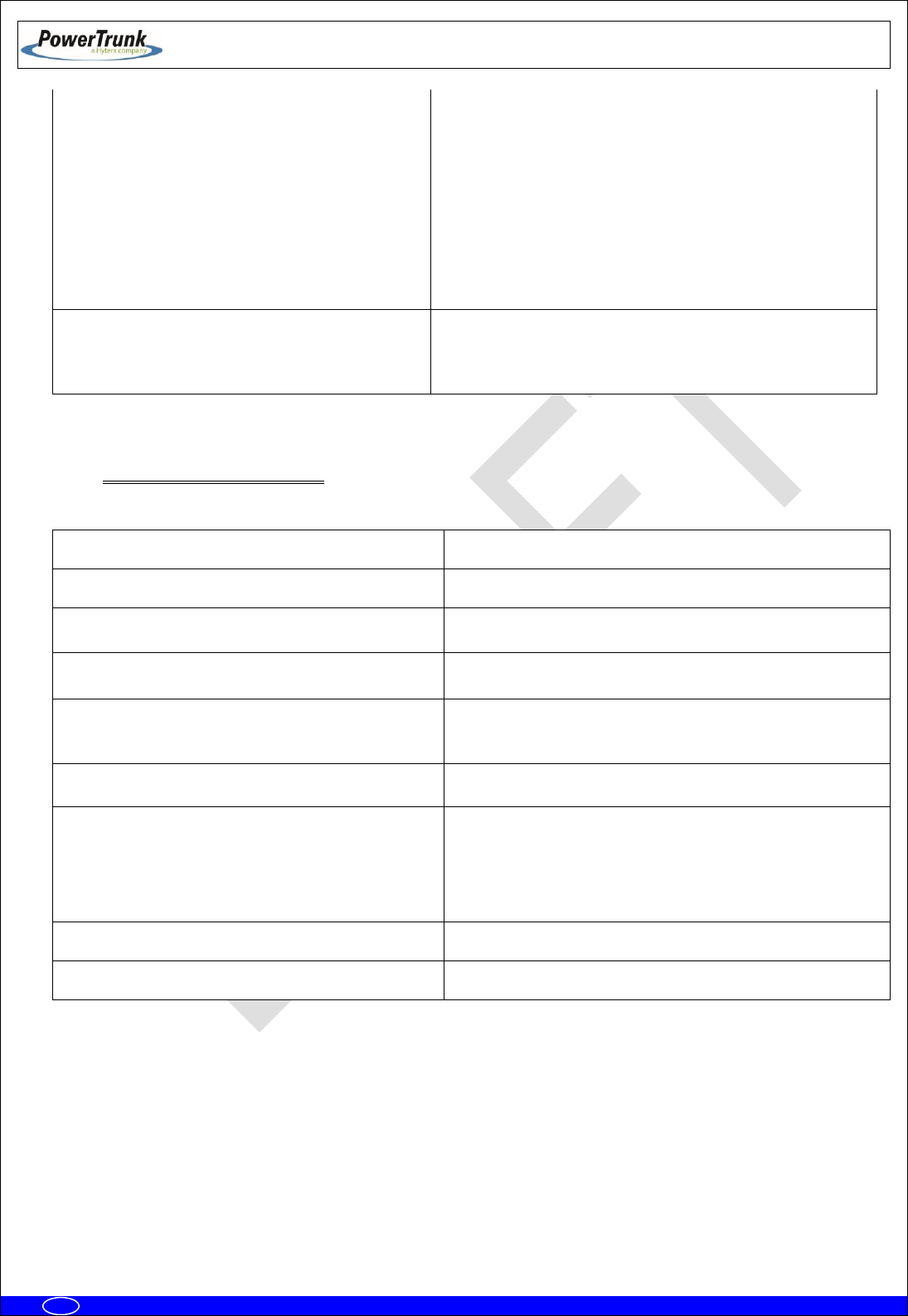
The following table displays all the MBS Unit available models, together with their respective
frequency band and maximum RF transmitted power.
MBS Unit:
Frequency band:
Nominal transmitter
output power
Maximum transmitter
output power
D148H01PT
350-370 MHz
10 W
12.6 W
D148P01PT
380-400 MHz
10 W
12.6 W
D148701PT
409-430 MHz
10 W
12.6 W
D148101PT
425-470 MHz
10 W
12.6 W
D148K01PT
763-806 MHz
10 W
12.6 W
D148N01PT
806-870 MHz
10 W
12.6 W
This manual is common to all the equipment models, including all their options and accessories.
The proper operation of any electronic device depends on its correct use. Therefore, it is
recommended to follow the instructions showed in this manual.
.

TETRA MBS UNIT. INSTALLATION GUIDE
F067646PT_2800
Page 6 of 62
en
2. UNPACKING AND CHECKING
The equipment is supplied with all the necessary materials for the installation, either on a mast, on a
wall or over the PBS Accessory:
MBS Unit includes the followings items
One power connector.
One Ethernet connector
RF super-flexible wire N-Male – N-Male.
Brackets for the installation.
Besides, in some types of installation, as detailed below, it is necessary an additional material that is
NOT supplied with the equipment.
IMPORTANT: If any of the necessary elements to carry out the installation process described in this
guide is missing or damaged, please contact your supplier.

TETRA MBS UNIT. INSTALLATION GUIDE
F067646PT_2800
Page 7 of 62
en
3. PREVIOUS CONSIDERATIONS
This manual contains information about instructions for installation, maintenance and use. Read the
following pages before using this equipment.
It is not advisable to switch on the equipment without having previously connected the antenna
otherwise irreparable damage could be. It is important to use an antenna adjusted to the work frequency.

TETRA MBS UNIT. INSTALLATION GUIDE
F067646PT_2800
Page 8 of 62
en
4. INFORMATION ON SAFETY AND ELECTROMAGNETIC
COMPATIBILITY
4.1 GENERAL CONSIDERATIONS ABOUT SAFETY
PLEASE READ THESE INSTRUCTIONS CAREFULLY FOR IMPORTANT INFORMATION ABOUT
SAFELY OPERATING THIS PRODUCT
Most electronic equipment are susceptible to electromagnetic interference if they are not duly
protected. If the MBS Unit is placed near unprotected electronic devices, they may malfunction.
Only cables that fulfil the characteristics specified in this document must be used. Communication
cables must be shielded and earthed at both ends.
Take care when handling the MBS Unit. It has edges, which may cut if handled incorrectly.
Do not attempt to dismantle this product. Servicing and repairs to this product must be performed by
trained service technicians at PowerTrunk approved service centres.
PowerTrunk has not approved any changes or modifications to this device by the user. Any changes
or modifications could void the user’s authority to operate the equipment.
Only fit an approved accessory. If a non-approved accessory is fitted, it may compromise the product
safety ratings and may void any product warranty.
Maintenance and repair of this device must be carried out by qualified personnel only.
TETRA MBS UNIT. INSTALLATION GUIDE
F067646PT_2800
Page 9 of 62
en
4.2 OPERATION AND EXPOSURE TO RF ENERGY
It is the responsibility of the person operating the product to ensure that it is operated safely at all
times, and that local laws and regulations governing the usage of Radio Frequency (RF) wireless devices are
observed. Obey all signs and instructions relating to the usage to RF wireless devices.
PowerTrunk designs and manufactures products to meet strict guidelines and international standards
relating to Radio Frequency (RF) energy and the potential health risks associated with using RF wireless
devices. If you have any concerns relating to long term health risks associated with using RF wireless
devices, you should obtain advice from your employer.
FCC radiation exposure statement
This radio is intended for use in occupational/controlled applications where users have been made
aware of the potential risks for exposure and can exercise control over their exposure. This product is not
authorised for general population, consumer or similar use. This transmitter must not be co-located or
operated in conjunction with any other antenna or transmitter.
This equipment complies with FCC and ISED radiation exposure limits set forth for an uncontrolled
environment. The antenna should be installed and operated with minimum distance of 2 m between the
radiator and your body. This transmitter must not be co-located or operating in conjunction with any other
antenna or transmitter.
FCC compliance labelling on RF Exposure
The following compliance product labelling can be found in a conspicuous location of the MBS Unit
radio for North America market:
FCC notice on operating the device
The device may contain functions that are not operational in U.S Territories except as noted in the
certification filing. Devices may be restricted in frequency by the FCC TCB Grant. Please refer to it for
allowed frequency ranges. The TCB Grant may have extended frequencies as noted in the certification filing
and Section 2.927(b) may apply to the authorisation. The device complies with 47 CFR Part 90.203 (e), in
that the operator cannot directly program the transmit frequencies using the normal accessible external
controls. All instructions detailed in this manual must be followed in order to ensure compliance with RF
exposure limits.
Failure to observe these restrictions may result in exceeding the FCC RF exposure limits.
ISED Canada information on RF Exposure
The Government of Canada provides further information about RF Exposure by means of official
publications that are available on the following website:
http://www.ic.gc.ca/eic/site/smt-gst.nsf/eng/sf01904.html
TETRA MBS UNIT. INSTALLATION GUIDE
F067646PT_2800
Page 10 of 62
en
4.3 IMPORTANT SAFETY NOTES ABOUT THE ANTENNA
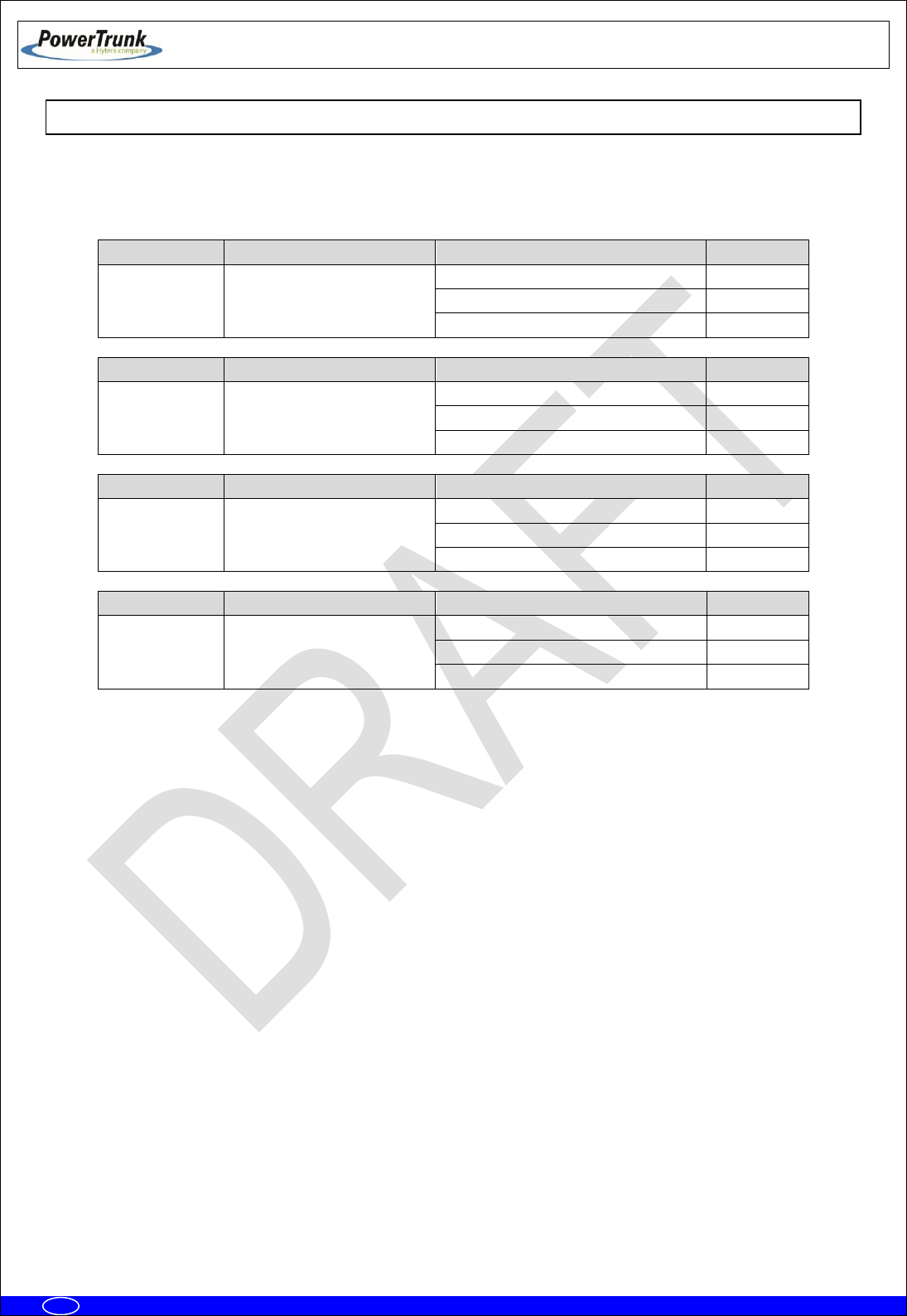
This radio has been approved by FCC and ISED to operate with the antenna types listed below with
the maximum permissible gain indicated. Antenna types not included in this list, having a gain greater than
the maximum gain indicated for that type, are strictly prohibited for use with this device.
MODEL
CERTIFICATION NUMBER
TYPE OF ANTENNA
MAX.GAIN
MBS Unit –7
(409-430 MHz)
FCC ID: WT7PTRNKTMBS410
IC: 8624A-PTMBS410
Vertically polarised panel antenna
11.0 dBi
Cross-polarised panel antenna
15.0 dBi
Vertically polarised collinear antenna
11.15 dBi
MODEL
CERTIFICATION NUMBER
TYPE OF ANTENNA
MAX.GAIN
MBS Unit –1
(425-470 MHz)
FCC ID: WT7PTMBS450B
IC: 8624A-PTMBS450B
Vertically polarised panel antenna
11.0 dBi
Cross-polarised panel antenna
15.0 dBi
Vertically polarised collinear antenna
11.15 dBi
MODEL
CERTIFICATION NUMBER
TYPE OF ANTENNA
MAX.GAIN
MBS Unit –K
(763-806 MHz)
FCC ID: WT7PTMBS760B
IC: 8624A-PTMBS760B
Vertically polarised panel antenna
16.5 dBi
Cross-polarised panel antenna
18.0 dBi
Vertically polarised collinear antenna
11.15 dBi
MODEL
CERTIFICATION NUMBER
TYPE OF ANTENNA
MAX.GAIN
MBS Unit –N
(806-870 MHz)
FCC ID: WT7PTMBS800B
IC: 8624A-PTMBS800B
Vertically polarised panel antenna
16.5 dBi
Cross-polarised panel antenna
18.0 dBi
Vertically polarised collinear antenna
11.15 dBi
Only use PowerTrunk approved antennas with this product. The use of non-approved antennas may
damage the product, will result in the non-compliance with regulatory requirements, will compromise the
product safety ratings, will reduce the length of operating time and will invalidate the product warranty.
Once the antenna has been installed, follow the guidelines for exposure of the human body to high
and low frequency electromagnetic fields. Follow the supplier’s / manufacturer’s instructions.
NEVER use your device without an antenna attached. Transmitting without an antenna may damage
your device
NEVER touch the antenna when your device is transmitting. This may cause a minor burn to the skin
and may affect the operational range of the antenna.
NEVER use your device if the antenna shows signs of damage.

TETRA MBS UNIT. INSTALLATION GUIDE
F067646PT_2800
Page 11 of 62
en
4.4 ELECTROMAGNETIC COMPATIBILITY REGULATORY INFORMATION (FCC AND ISED)
These devices generate, use and radiate RF energy and, if not installed and used in accordance with
the instruction manual, may cause harmful interference to radio communications.
FCC interference statement and compliance labelling
This device complies with Part 15 of the FCC Rules and Industry Canada’s licence-exempt RSS
standards. Operation is subject to the following two conditions: (1) this device may not cause interference,
and (2) this device must accept any interference, including interference that may cause undesired operation
of the device.
A label with the text above can be found in a conspicuous location of the MBS Unit for North America
market.
FCC Class B digital device notice
This equipment has been tested and found to comply with the limits for a Class B digital device, pursuant
to part 15 of the FCC Rules. These limits are designed to provide reasonable protection against harmful
interference in a residential installation. This equipment generates, uses and can radiate radio frequency
energy and, if not installed and used in accordance with the instructions, may cause harmful interference to
radio communications. However, there is no guarantee that interference will not occur in a particular
installation. If this equipment does cause harmful interference to radio or television reception, which can be
determined by turning the equipment off and on, the user is encouraged to try to correct the interference by
one or more of the following measures:
- Reorient or relocate the receiving antenna.
- Increase the separation between the equipment and receiver.
- Connect the equipment into an outlet on a circuit different from that to which the receiver is
connected.
- Consult the dealer or an experienced radio/TV technician for help.
ISED Canada ICES-003 compliance labelling
This Class B digital apparatus has been fully tested and found to comply with the Canadian ISED
(Innovation, Science and Economic Development) standard ICES-003. A label with the text below can be
found in a prominent location of the radio for North America market:
CAN ICES-3 (B) / NMB-3 (B)

TETRA MBS UNIT. INSTALLATION GUIDE
F067646PT_2800
Page 12 of 62
en
4.5 UL / SAFETY CERTIFICATIONS
The MBS Unit is UL certified, and complies with the requirements for electronic
devices to minimise risks such as fire, electric shocks or injuries to the operator that may
be caused in operation. File number is the following: E318948.
MBS Unit complies with the standard UL 60950-1 and UL 60950-22, including the
National Differences for United States, Canada and CENELEC (Europe), and it has CB
Test Certificate.
4.6 EMC, SAFETY AND RF EXPOSURE STANDARDS
The equipment has been designed according to the following standards:
ETSI EN 300 394-1
Terrestrial Trunked Radio (TETRA);Conformance testing
specification; Part 1: Radio
ETSI EN 301 489-1
Electromagnetic Compatibility and Radio spectrum Matters
(ERM); ElectroMagnetic Compatibility (EMC) standard for
radio equipment and services; Part 1: Common technical
requirements
ETSI EN 301 489-5
ElectroMagnetic Compatibility (EMC) standard for radio
equipment and services; Part 5: Specific conditions for
Private land Mobile Radio (PMR) and ancillary equipment
(speech and non-speech) and Terrestrial Trunked Radio
(TETRA)
EN 50121-4
Railway applications - Electromagnetic compatibility - Part
4: Emission and immunity of the signaling and
telecommunications apparatus
EN 60950-1 / IEC 60950-1 / UL 60950-1 / CSA
60950-1
Information technology equipment - Safety -- Part 1:
General requirements
EN 60950-22 / IEC 60950-22 / UL 60950-22 /
CSA 60950-22
Information technology equipment - Safety -- Part 22:
Equipment to be installed outdoors
EN 50383
Basic standard for the calculation and measurement of
electromagnetic field strength and SAR related to human
exposure from radio base stations and fixed terminal
stations for wireless telecommunication systems (110 MHz
- 40 GHz)
EN 50385
Product standard to demonstrate the compliance of radio
base stations and fixed terminal stations for wireless
telecommunication systems with the basic restrictions or
the reference levels related to human exposure to radio
frequency electromagnetic fields (110 MHz - 40 GHz) -
General public
Most of these standards ensure the essential requirements set out in Article 3 of Directive 2014/53/UE.

TETRA MBS UNIT. INSTALLATION GUIDE
F067646PT_2800
Page 13 of 62
en
4.7 MECHANICAL AND ENVIRONMENTAL STANDARDS
The equipment complies with the following standards:
4.7.1 STANDARDS CENELEC
EN 60068-2-1
* No Functional. - 104 ºF. Duration: 72 h
* Functional: - 86 ºF. Duration: 16 h.
Environmental testing -- Part 2-1: Tests - Test A: Cold
EN 60068-2-2
* No Functional. + 185 ºF. Duration: 72 h
* Functional: + 140 ºF. Duration: 16 h.
Environmental testing -- Part 2-2: Tests - Test B: Dry heat
EN 60068-2-78
* Functional + 140 ºF 93%. Duration 21 days.
Environmental testing -- Part 2-78: Tests - Test Cab: Damp
heat, steady state
EN 60068-2-30
* Functional: 6 cycles 24 hours:
• 12 hours. Temperature: + 140 ºF. Relative
humidity: 95% ± 5%
• 12 hour: Temperature + 77 ºF. Relative
humidity: 98% ± 5%
Environmental testing -- Part 2-30: Tests - Test Db: Damp
heat, cyclic (12 h + 12 h cycle)
EN 60068-2-11
No functional: 672 hours. + 95 ºF +/- 35.6 ºF. 5%
ClNa
Environmental testing -- Part 2: Tests - Test Ka: Salt mist
EN 60529
* No functional. IP66
Degrees of protection provided by enclosures (IP Code).
EN 60068-2-9
* No functional.
• Proc. B: 20 hours of solar radiation and 4
hours of darkness
• Temperature: +104 ºF
• Humidity: 65%
• Duration: 10 days
Environmental testing -- Part 2: Tests - Guidance for solar
radiation testing.
EN 60068-2-64
* No functional:
• Duration: 30 minutes by axe
• 5-20 Hz. ASD: 1 m2/s3.
• 20-200 Hz. ASD; - 3dB/oct
Environmental testing -- Part 2-64: Tests - Test Fh:
Vibration, broadband random and guidance.
EN 60068-2-6
* No functional:
• Duration: 5 sweep by axe
• 5-9 Hz. Displacement 1.2 mm.
• 9-200 Hz. Acceleration 4 m/s2
Environmental testing -- Part 2-6: Tests - Test Fc: Vibration
(sinusoidal).
TETRA MBS UNIT. INSTALLATION GUIDE
F067646PT_2800
Page 14 of 62
en
UNE-EN 60598
* Vibration type: Sine swept
* Frequency range: From 10 to 55 Hz
* Amplitude (peak):
• 10 Hz Amplitude (peak): 1.4 mm
• 38 Hz Amplitude (peak): 20 m/s2
• 55 Hz Amplitude (peak): 20 m/s2
* Number of axes: 3 axes
* Swept ratio: 1 Oct./min.
* Duration: 30 min./axis
Vibration: simulation of the fixing between MBS unit and
mast.
Eurocode UNE-EN 1991-1-4
* Wind speed: 200 km /h (55.55 m/s) (Safety
factor 1.5)
* Height in post: 20 m
Protection for avoiding damages either in the enclosure
and the fixing parts, due to meteo effects such as strong
gusts of wind.
4.7.2 STANDARDS MIL-STD 810G
MIL-STD-810G METHOD 502.5 procedure I, (C2):
- 104 ºF. Duration: 72 h
Cold (Storage and transportation).
MIL-STD-810G METHOD 502.5 procedure I, (C1):
- 86 ºF. Duration: 16 h
Cold (Operation).
MIL-STD-810G METHOD 501.5 procedure I (A1): +
185 ºF. Duration: 72 h
Dry Heat (Storage and transportation).
MIL-STD-810G METHOD 501.5 procedure I (A2): +
140 ºF. Duration: 16 h
Dry Heat (Operation).
MIL-STD-810G - Method 507.5, procedure II
(Aggravated): (10 cycles, 24 hours) 86 ºF - 140 ºF
at 95%rH.
Humidity.
MIL-STD-810G - Method 509.5
672 hours. + 95 ºF +/- 35.6 ºF. 5% ClNa.
Salt Fog.
MIL-STD-810G - Method 505.5:
- Proc. B: 20 hours of solar radiation and 4
hours of darkness
- Temperature: +104 ºF
- Humidity: 65%
- Duration: 10 days
Solar Radiation (Sunshine).
MIL_STD-810G 514.6, Test procedure I, Category
4, table C-VI C3 (Figure 514,6 C-3)
Vibration.
MIL-STD-810G 516.6 Test procedure I and III, 0.71
oz 11 ms, half sinus
Shock.
TETRA MBS UNIT. INSTALLATION GUIDE
F067646PT_2800
Page 15 of 62
en
5. EQUIPMENT DESCRIPTION
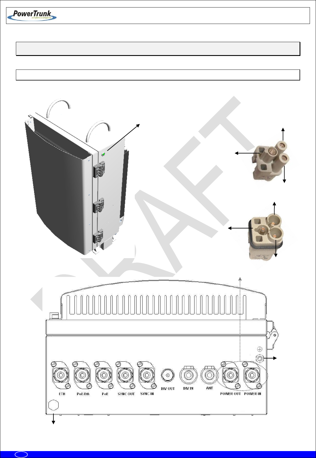
5.1 VIEW
2
1
3
Male panel connector
1
2
Female cable connector
3
State
LED
5
4

TETRA MBS UNIT. INSTALLATION GUIDE
F067646PT_2800
Page 16 of 62
en
5.2 CONNECTORS
1.- Terminal with the following meaning depending on the MBS Unit Power option:
- AC MBS Units: Neutral contact (N).
- DC MBS Units: Negative contact (-).
2.- Terminal with the following meaning depending on the MBS Unit Power option:
- AC MBS Units: Line contact (L).
- DC MBS Units: Positive contact (+).
3.- Power supply Earth contact.
4.- Pressure equalizer.
5.- Chassis Earth contact.
ETH: Connector that allows Ethernet connection between MBS Units. It also can be used as
Maintenance Ethernet connector.
PoE/ETH: Power Over Ethernet (IEEE 802.3af) connector. It provides power supply (48 VDC) and
Ethernet connection to a PoE radio link. It can be used as Maintenance Ethernet connector if there is
not radio link (Poe) connected. If the MBS Unit has the SNI IP option this connector is Layer 3.
PoE: Power Over Ethernet (IEEE 802.3af) connector. It provides power supply (48 VDC) and
Ethernet connection to a PoE radio link. If the MBS Unit has the SNI IP option this connector is Layer
3.
SYNC OUT: Synchronism output connector. It provides synchronism to a second MBS Unit through
its SYNC_IN connector.
SYNC IN: Synchronism input connector.
DIV OUT: Output reception connector. It provides the receiver chain 2 to the next MBS Unit through
its DIV IN connector.
DIV IN: Reception antenna connector (receiver chain 2). It is connected to an antenna or to a MBS
Unit DIV OUT connector (diversity 2).
ANT: Transmission/reception antenna power connector (receiver chain 1).
POWER OUT: Output power supply connector. It provides power supply to another MBS Unit with
the same Power Supply option.
POWER IN: Input power supply connector (VAC or VDC).
TETRA MBS UNIT. INSTALLATION GUIDE
F067646PT_2800
Page 17 of 62
en
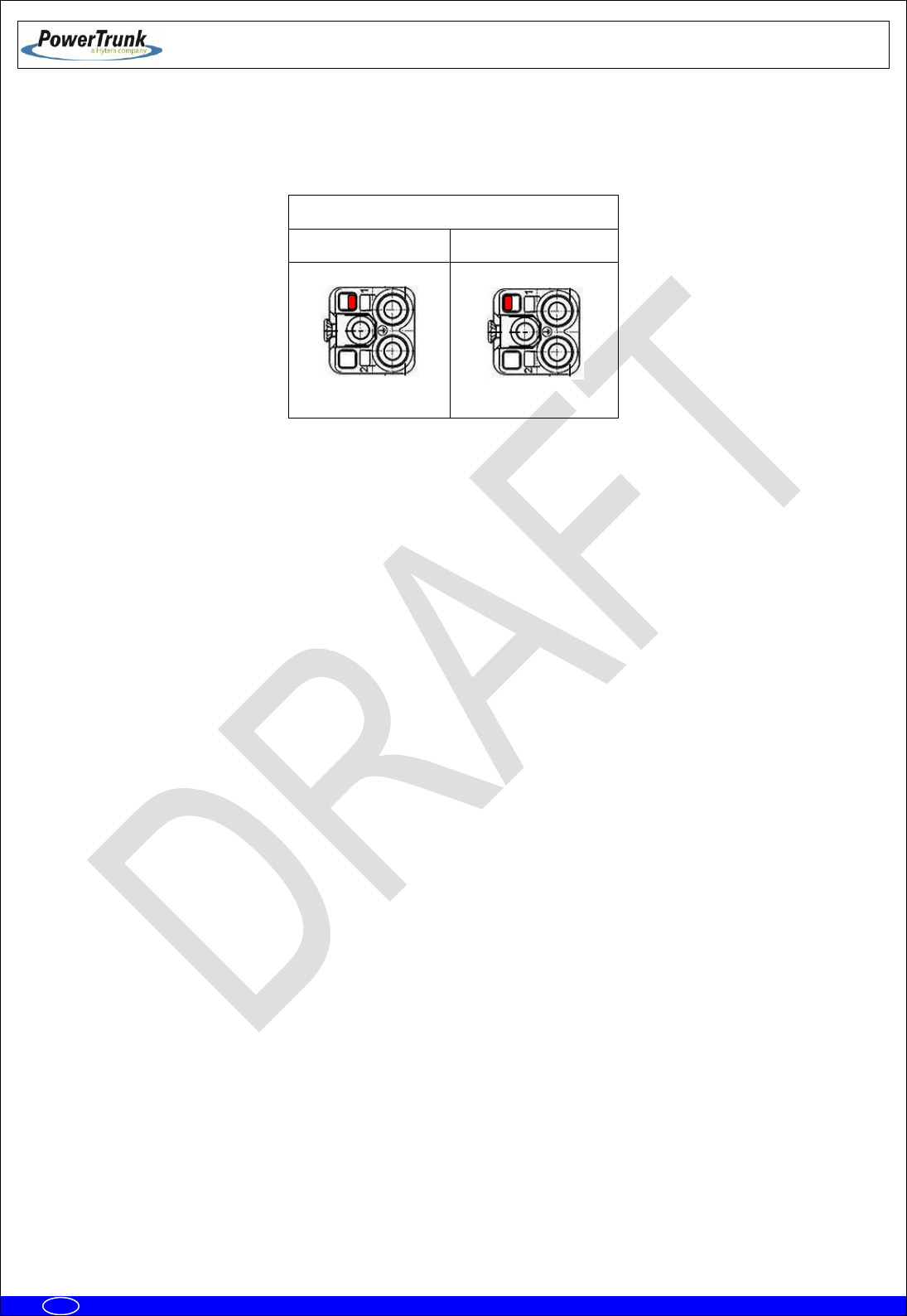
Note: POWER_IN and POWER_OUT connectors have a coding key to avoid wrong connections; on the
following table is showed the location of this coding key depending on the MBS Unit power supply option.
External view of power supply panel connector
AC Power Supply
DC Power Supply
Note: The amount of power delivered by both PoE and PoE/ETH connectors to the radio links can not
exceed 35 W in total.
TETRA MBS UNIT. INSTALLATION GUIDE
F067646PT_2800
Page 18 of 62
en
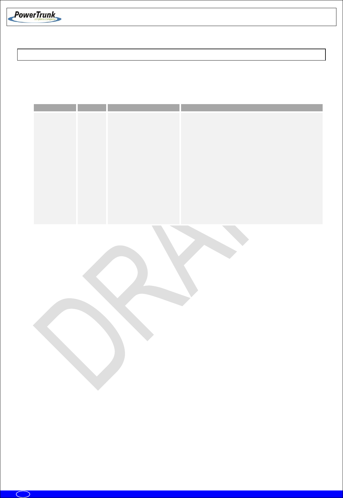
5.3 VISUAL INDICATORS
A MBS Unit has a LED indicator that, depending on its state, will indicate the function of the MBS Unit
The LEDs show the MBS Unit state:
LED
TYPE
NORMAL STATE
FUNCTIÓN
STATE
Tricolor
Green ON / Orange ON
Green On: MBS Unit is operating and
transmitting.
Green flashing: MBS Unit initializing
Red On: There is no link with CNC and no
control from any LSC.
Red flashing: When MBS Unit is controlled by
the CNC, showing any kind of alarm other than
the communication one is NOT OK.
Orange On: MBS Unit is operating and
transmitting in fallback mode.
Orange flashing: When MBS Unit is in
fallback mode, showing any kind of alarm other
than the communication one is NOT OK.
OFF: The equipment is either without power
source or is damaged.
TETRA MBS UNIT. INSTALLATION GUIDE
F067646PT_2800
Page 19 of 62
en
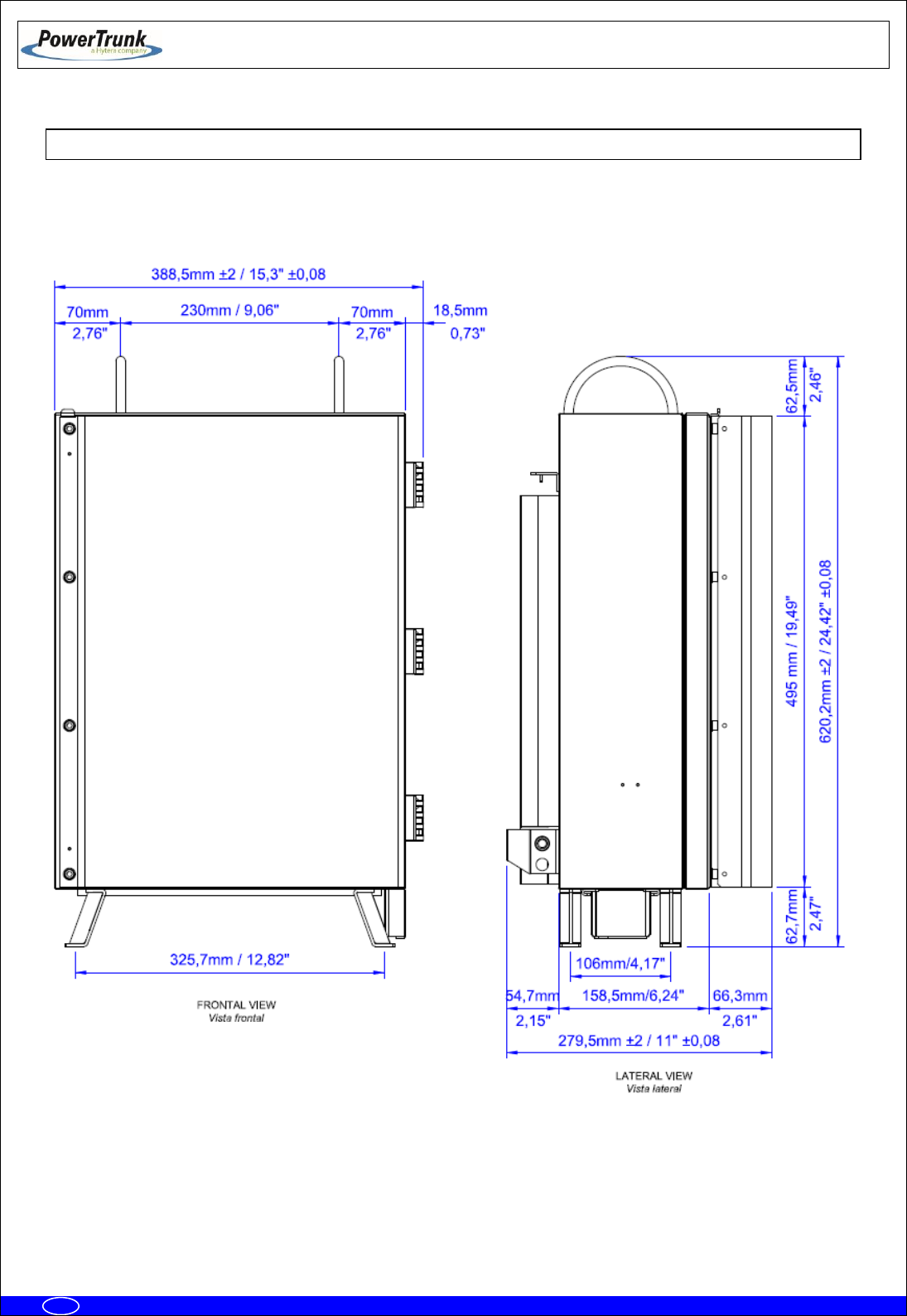
5.4 DIMENSIONS

TETRA MBS UNIT. INSTALLATION GUIDE
F067646PT_2800
Page 20 of 62
en
6. INSTALLATION GUIDE
The following recommendations must be followed before powering on the MBS Unit module.
Next diagram shows the steps to be followed to carry out the installation:
Verification of equipment needed
Basic Pre-Configuration
Final location installation
Final Configuration/Verification

TETRA MBS UNIT. INSTALLATION GUIDE
F067646PT_2800
Page 21 of 62
en
6.1 NECESSARY EQUIPMENT
Make sure you have the necessary equipment depending on the configuration to
install. If any of the elements necessary to carry out the installation process
described in this manual, were lost or damaged, contact your supplier and / or
installer.
Necessary equipment
Element
Code
Comments
MBS Unit
D148X01PT
“x” varies depending on band.
Each MBS Unit includes:
- MBS Unit equipment
- Power supply cable connector
- Ethernet cable connector
- RF superflexible wire N-Male ↔ N-Male
- Brackets for installation
Anti-vandal kit
D014000PT
It is only necessary if anti-vandal protection is
required.
Ethernet cable connector
225120
Every MBS Unit includes one connector of this
type; if a MBS Unit must be connected to two
radio links, it is necessary to have a second unit.
RF superflexible wire N-Male
↔ N-Male
208931
Each MBS Unit includes one cable of this type;
if a MBS Unit requires diversity 2 on reception it
is necessary to have a second unit.
Additional carrier
interconnection kit
D014001PT
It is mandatory in case of connecting a second
MBS Unit to the first MBS Unit.
NMS Server-Client Rugged
Laptop
D484904XPT
It is only necessary if the MBS Unit is required
to operate in Isolated Mode.
Mounting Accessories
PBS Accessory
D014002PT
Transport hand truck accessory for MBS Unit.

TETRA MBS UNIT. INSTALLATION GUIDE
F067646PT_2800
Page 22 of 62
en
Additional equipment to be considered for installation
Element
Comments
Cable to power the MBS Unit.
See features in external power connection section. One power supply
cable connector is supplied with the MBS Unit.
Ethernet cable to connect PoE
radio links
See features in Ethernet connection section. One Ethernet cable
connector is supplied with the MBS Unit.
Antenna coaxial cable and
antenna.
See features in Antenna connection section.
Tools
Element
Comments
Toolbox
In addition to the usual material used for installations (wrenches,
screwdrivers ...) it is necessary to use:
- Torque wrench for 17 mm hexagonal nut capable of delivering 15
Nm.
- Vulcanizable tape.
Ethernet Cable
Cable to make specific maintenance tasks in the field

TETRA MBS UNIT. INSTALLATION GUIDE
F067646PT_2800
Page 23 of 62
en
6.2 BASIC PRE-CONFIGURATION
Before connecting the MBS Unit to the infrastructure it should have the IP address correctly
configured in order to have remote access once it is connected (to set the IP address, see the configuration
chapter (F067220PT) in technical manual).
Steps:
Apply power supply to the MBS through its POWER_IN connector.
Wait 3 minutes until the MBS Unit initializes.
Connect the PC, to set the IP address, to the ETH connector.
Change the IP address according to the network IP addressing plan.
Check that IP address was successfully changed through a “ping” from the PC to the new IP address
of the MBS Unit.

TETRA MBS UNIT. INSTALLATION GUIDE
F067646PT_2800
Page 24 of 62
en
6.3 INSTALLATION
The MBS has been designed to be mounted on both mast/pole, on a wall or over a PBS Accessory.
This chapter provides the necessary steps to be followed for a right MBS Unit installation.
At least two people are required to carry out the installation of a MBS Unit on a mast/pole.
Note: MBS Unit has been designed to operate in vertical position. In case of being necessary the operation
in horizontal position, the client will must check with the manufacturer. In this case, the range of temperature
will be reduced (-86 ºF to 122 ºF).
TETRA MBS UNIT. INSTALLATION GUIDE
F067646PT_2800
Page 25 of 62
en
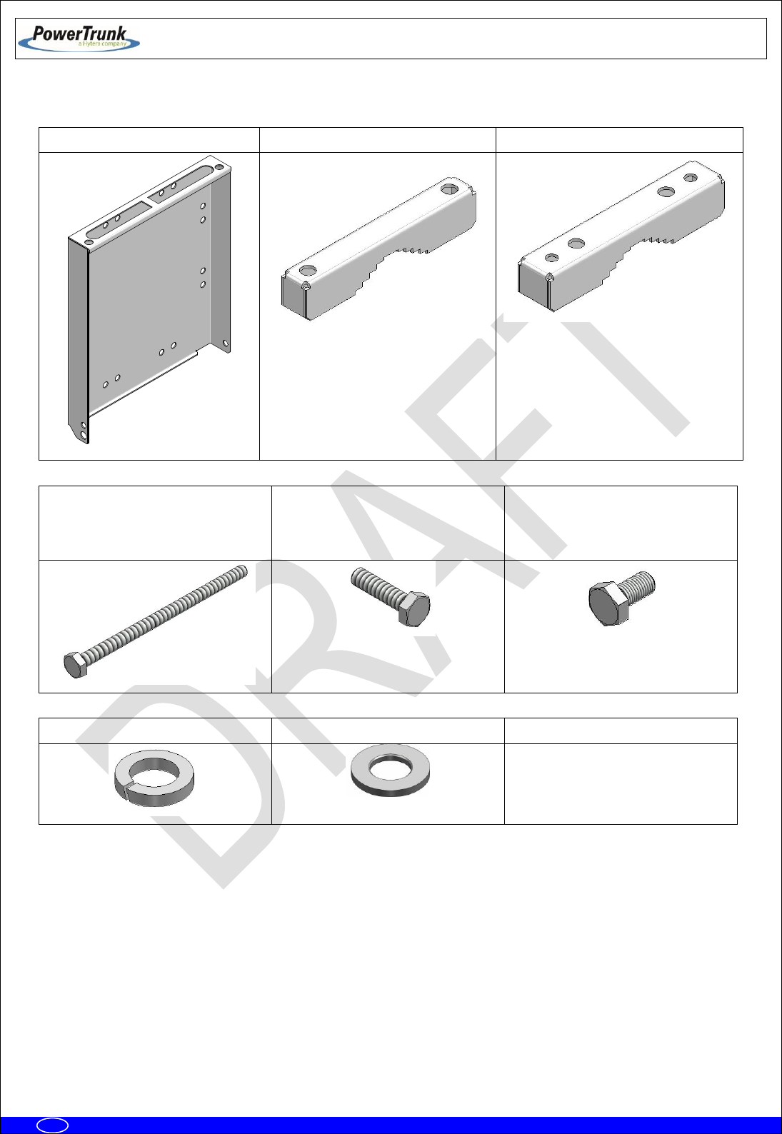
Bracket system:
1 x Bracket
2 x clamp (2 holes)
2 x clamp (4 holes)
4 x Bolt M10x180
(Clamp attachment)
6 x Bolt M10x40
(lateral attachment MBS-Bracket
& Clamp-Bracket)
2 x Bolt M10x20
(Top attachment MBS-Bracket)
12 x Grower washer DIN 127 Ø10
12 Plain washer DIN125 x Ø10
---

TETRA MBS UNIT. INSTALLATION GUIDE
F067646PT_2800
Page 26 of 62
en
6.3.1 MAST/POLE INSTALLATION
6.3.1.1 MAST/POLE SELECTION
The types of section of the mast/pole where the MBS Unit can be mounted are the followings:
Circular section: Diameter from 30 mm to 130 mm
Square section: From 30 mm x 30 mm to 85 mm x 85 mm.
L section: From 30 mm x 30 mm to 110 mm x 110 mm.
In the choice of the mast/pole where the MBS Unit is being installed the following recommendations
must be followed:
The mast/pole has to support the loads due to the installation of some elements on
them.
The mast/pole has to support the loads due to the action of the wind, snow as well as its
own weight, because these are going to induce its flexion.
o The mast/pole must have the enough inertia both lateral and frontal in order that the actions
of different loads do not induce permanent deformations on it.
The manufacturer of the mast/pole must evaluate the structural factor of the mast/pole
correctly depending on its type.
It is necessary to take into account both the height where the MBS Unit is installed and
its weight/dimensions (See section “MBS Unit” in chapter (F067326PT) “SBS Technical
Description” in the Standard Technical Manual).
It is recommended to choose a lattice mast/pole in case of this one has a high height
and it is going to be submitted to important flexion efforts. In any case, it is
responsibility of the manufacturer of the mast/pole to determine if the resistant
section of mast/pole is suitable.
The brackets should be installed tight enough to support the MBS Unit without causing deformation
of the mast/pole or areas of corrosion.
TETRA MBS UNIT. INSTALLATION GUIDE
F067646PT_2800
Page 27 of 62
en
Once mounted in its definitive location, if the vandal resistant kit is available, it will prevent the
access / disassembly not authorized.
In case of installing more than one MBS Unit on the same mast/pole, it is recommended not to
mount one above the other one to avoid the heat transfer from the MBS Unit low to the MBS Unit high. If the
MBS Units have to be installed in the same vertical axis these must be oriented in different directions to
increase the separation of them as far as possible, depending on the length of wiring between both
equipments (1.5 m approximately).

TETRA MBS UNIT. INSTALLATION GUIDE
F067646PT_2800
Page 28 of 62
en
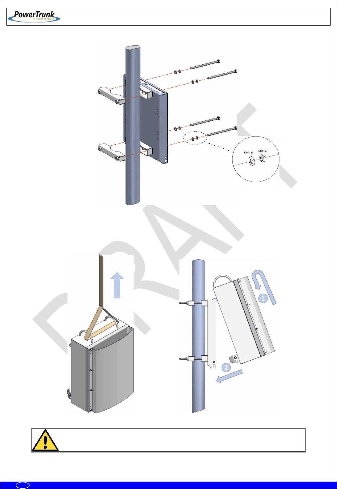
6.3.1.2 MAST/POLE MOUNTING INSTRUCTIONS
Steps to install a MBS on a mast/pole:
1. Place the MBS Unit bracket on the mast/pole as follows.
Note: Handle the MBS Unit bracket with care if it rests on the floor. Place some protection
underneath to prevent scratches on the surface.
a) Secure 4 holes clamps on the bracket by tightening the bolts with a 20 Nm torque, using a 17
mm torque wrench, do not forget to place the washers
b) Install the bracket to the desired final location on the mast/pole. Embrace the 2 holes clamps
and screw these to the bracket with a 17 mm wrench and 20 Nm torque. Due to the length of the
bolts it is advisable to screw them slowly.
TETRA MBS UNIT. INSTALLATION GUIDE
F067646PT_2800
Page 29 of 62
en
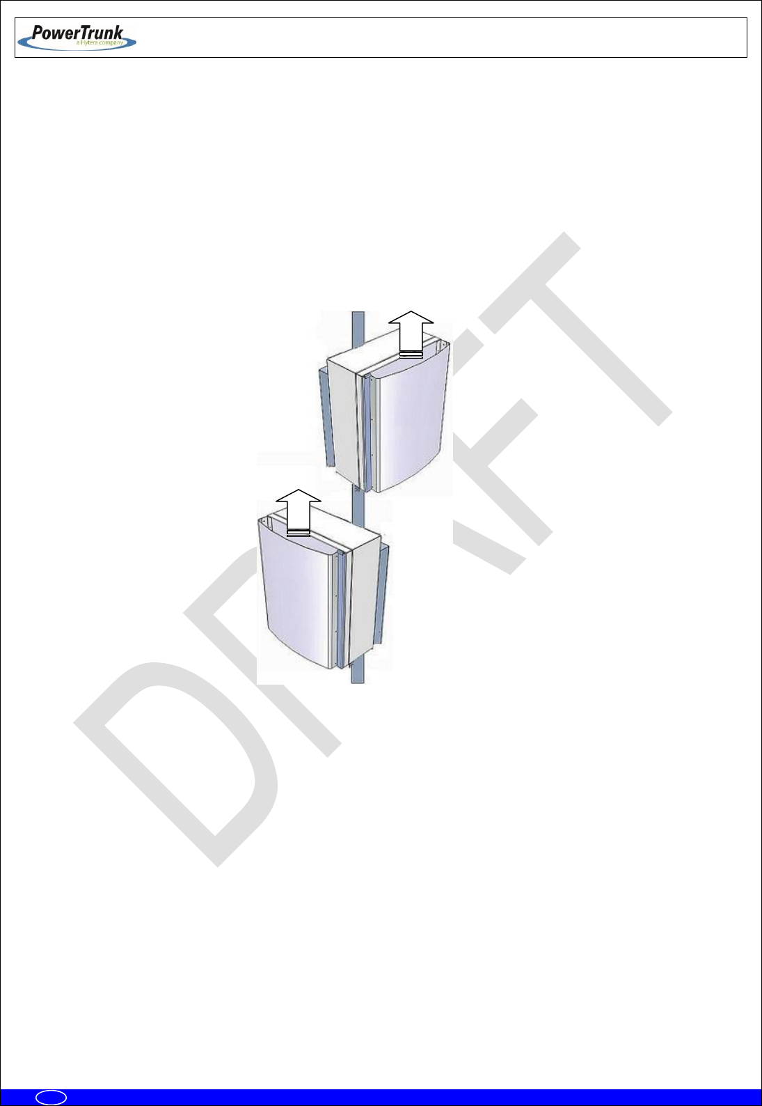
2. Place MBS Unit on the bracket as follows.
a) Raise the MBS Unit to the position where the bracket is placed on the mast/pole and hang it on
the bracket, tilting slightly to match the bracket guides as indicated in the following figure:
To prevent accidents during the MBS installation, for safety it is highly recommended
to use a second rope.

TETRA MBS UNIT. INSTALLATION GUIDE
F067646PT_2800
Page 30 of 62
en
b) Put the bolts of the MBS Unit and washers to the bracket with a 17 mm wrench and 25 Nm
torque.
Note: If anti-vandal kit is available (D014000PT), lateral bolts should be placed after mounting
the anti-vandal kit.
3. Make the necessary wiring connections as described in the connections section in this guide.

TETRA MBS UNIT. INSTALLATION GUIDE
F067646PT_2800
Page 31 of 62
en
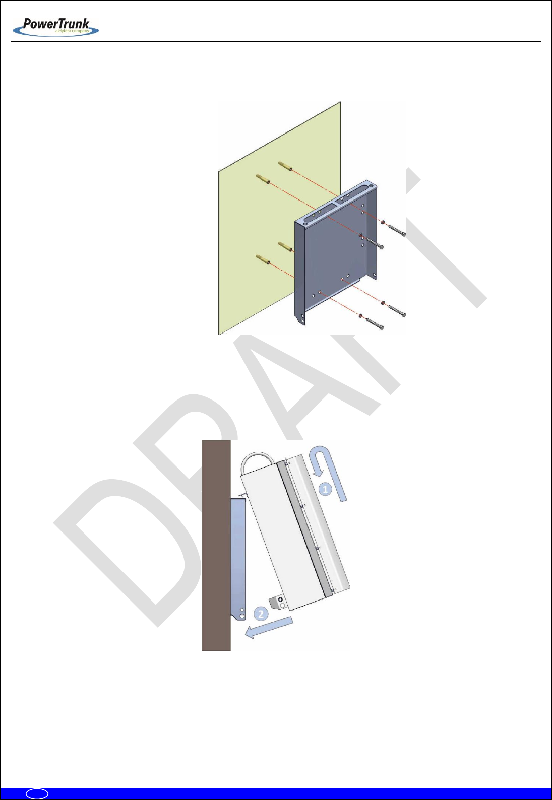
6.3.2 WALL INSTALLATION
To install the MBS Unit on a wall, make the following steps:
1. Mark the position of the holes using the bracket as a template itself with the help of a level
Note: To ensure proper ventilation there must be at least 700 mm clearance above and below each
MBS Unit. There must also be a minimum distance of 300 mm free on both sides of the MBS Unit.
Note: The screws, expansion bolts and washers needed to secure the brackets to wall are not
supplied with the unit.
The distance between the holes are shown in the following figure.
2. Drill holes on the wall and insert a rawlplug in each hole.
TETRA MBS UNIT. INSTALLATION GUIDE
F067646PT_2800
Page 32 of 62
en
3. Place the bracket over the rawlplug and insert the bolts and washers. Finally screw them with a 17
mm wrench and 20 Nm torque.
4. Place the MBS Unit on the bracket as follows.
a) Raise the MBS Unit to the position where the bracket is placed and hang it on the bracket, tilting
slightly to match the anchor guides as indicated in the following figure:
TETRA MBS UNIT. INSTALLATION GUIDE
F067646PT_2800
Page 33 of 62
en
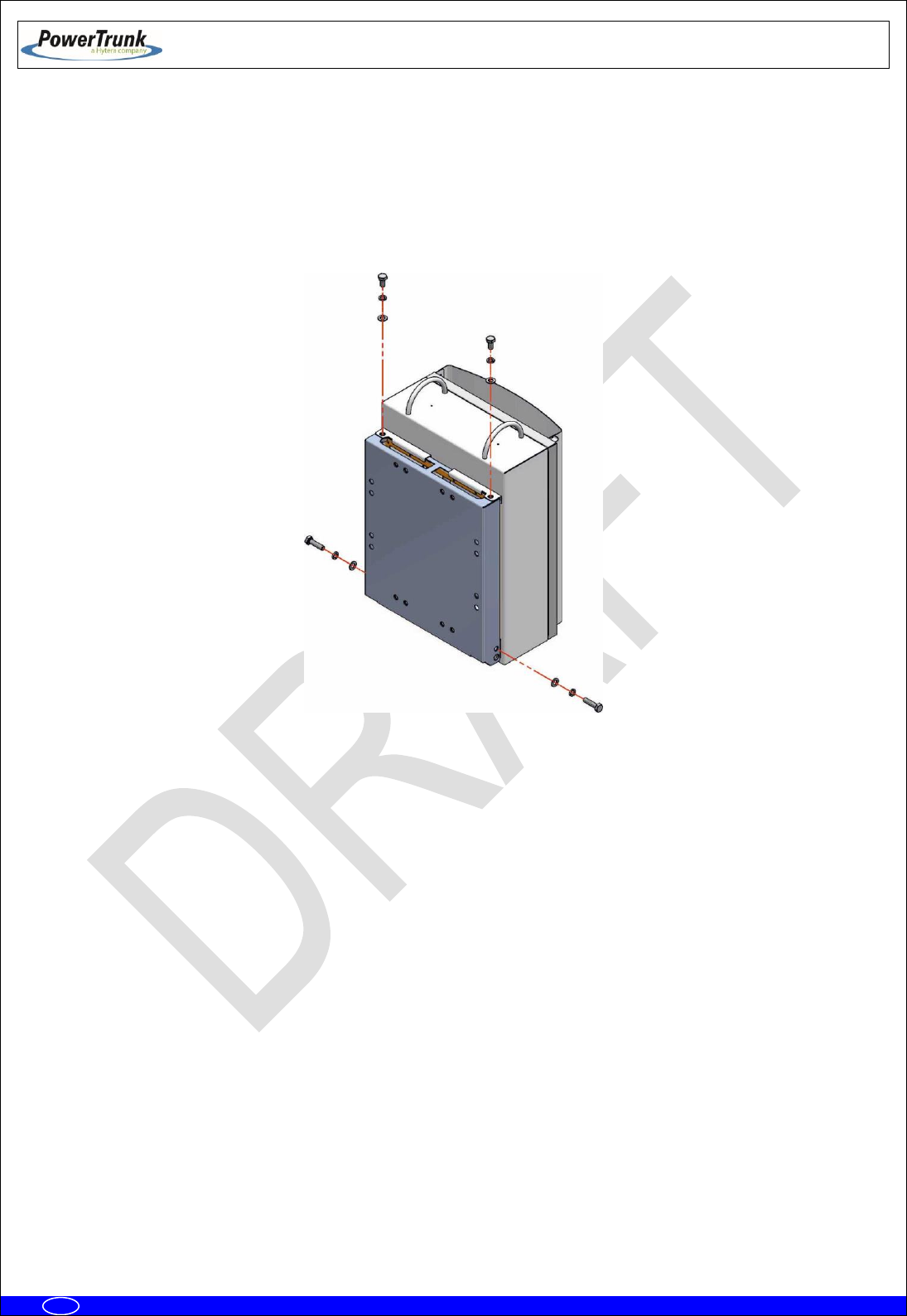
b) Put the bolts of the MBS Unit and washers to the bracket with a 17 mm wrench and 25 Nm
torque. The order is bolt + grower washer + plain washer.
Note: If anti-vandal kit is available (D014000PT), lateral bolts should be placed after mounting
the anti-vandal kit.
5. Make the necessary wiring connections as described in the connections section in this guide.
TETRA MBS UNIT. INSTALLATION GUIDE
F067646PT_2800
Page 34 of 62
en
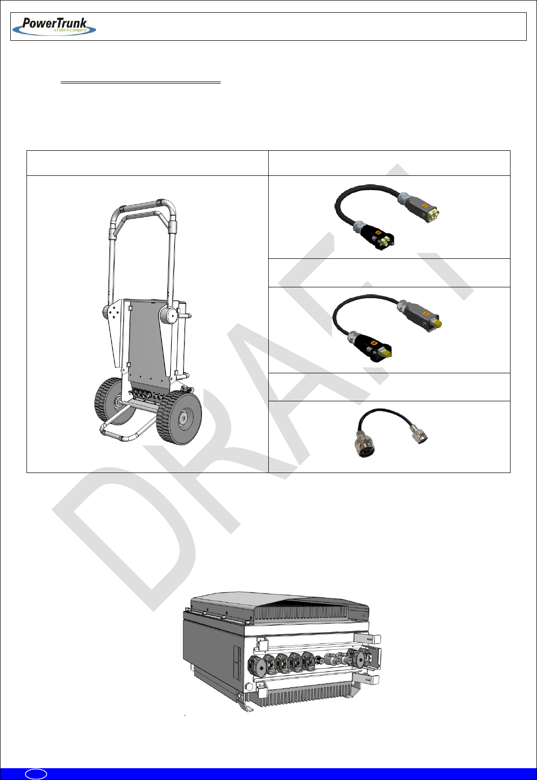
6.3.3 PBS ACCESSORY INSTALLATION
The PBS Accessory (D014009) is a hand truck element that allows one person to transport a MBS Unit.
PBS Accessory:
1 x PBS Hand Truck
1 x Power Cable
4 x Ethernet Cable
3 x RF Cable
The following steps must be done to install a MBS Unit over a PBS Accessory:
1. Put the MBS Unit in horizontal position, place it over the back radiator and remove all the connectors
covers except the covers of the PWR OUT and ETH connectors as shown in the following picture:
TETRA MBS UNIT. INSTALLATION GUIDE
F067646PT_2800
Page 35 of 62
en
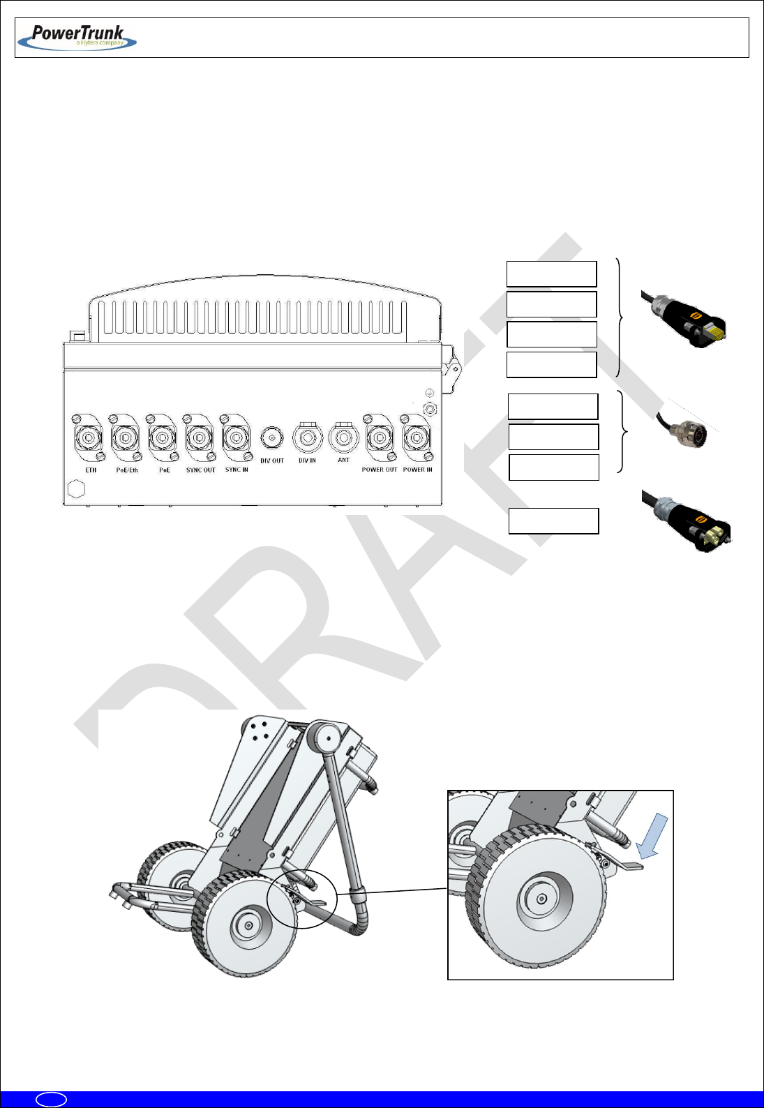
2. Connect the cables on its corresponding ports of the MBS Unit according to the following order:
4 x Ethernet Cables: PoE/ETH, PoE, SYNC OUT and SYNC IN
3 x RF Cables: ANT, DIV OUT and DIV IN
1 x Power Cable: POWER IN
Note: The POWER OUT and ETH connectors must be closed with covers.
3. After connecting all the cables into the MBS Unit, the hand truck must be placed in Operating
position to mount the carrier. In this position, the hand truck leans down backwards with the bracket
exposed to the front and the moving arm working as a supporting point.
Note: The brake system of the hand truck must be activated to avoid any movement during the
installation of the MBS Unit.
PoE/Eth
PoE
ANT
DIV OUT
DIV IN
SYNC IN
SYNC OUT
POWER IN

TETRA MBS UNIT. INSTALLATION GUIDE
F067646PT_2800
Page 36 of 62
en
4. Put the MBS Unit over the hand truck bracket as indicated below:
a) Lift up the MBS Unit until getting the bracket position and lean it softly to reach the anchor
guides as shown in the following figure:
b) Place the clamping washers and screws in the hand truck bracket with a torque wrench of 17
mm and torque 25 Nm. The order is the following:
1) Flat washer
2) Grower washer
3) Screw

TETRA MBS UNIT. INSTALLATION GUIDE
F067646PT_2800
Page 37 of 62
en
5. Connect one by one the cables previously fixed in the MBS Unit in the corresponding connectors of
the hand truck connector panel. Except the PWR OUT and ETH that will be covered, the rest of
cables must have a corresponding connector in the interconnection panel.
6. Verify that all the connections are secured with the panel connector locking system closed and that
correctly holds the aerial connector coming from the MBS Unit.
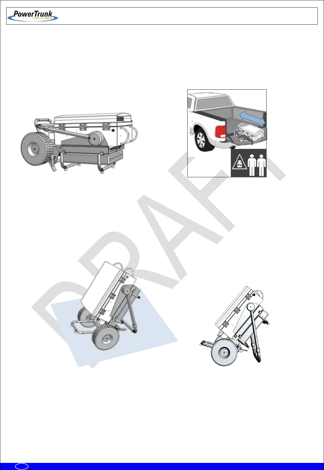
6.3.3.1 WORKING POSITIONS
The PBS Accessory permits 3 working positions: Manual Transport, Vehicle Transport and Operating
Position.
To get any of the positions previously mentioned, the following elements of the PBS accessory must be
taken into account:
Note: The wheels must be blocked in any other position different than Manual
Transport.
6.3.3.1.1 MANUAL TRANSPORT POSITION
To manually transport the MBS Unit with the PBS Accessory the wheels must be unblocked and the
adjustable handle has to be placed just as indicated below:
Wheel blocking system
Adjustable Handle
TETRA MBS UNIT. INSTALLATION GUIDE
F067646PT_2800
Page 38 of 62
en
6.3.3.1.2 VEHICLE TRANSPORT POSITION
To perform an vehicle transport of the MBS Unit with the PBS Accessory, the adjustable handle must be
placed to the front and the whole set must be inclined to the back using the adjustable handle as support
point as shown below:
Note: the set composed by MBS Unit and the PBS Accessory has a heavy weight, the actions of loading and
unloading into the vehicle must be done by at least two persons.
6.3.3.1.3 OPERATING POSITION
To correctly operate the set composed by the MBS Unit and PBS Accessory, the adjustable handle must be
placed backwards to use it as supporting point as shown below:
TETRA MBS UNIT. INSTALLATION GUIDE
F067646PT_2800
Page 39 of 62
en
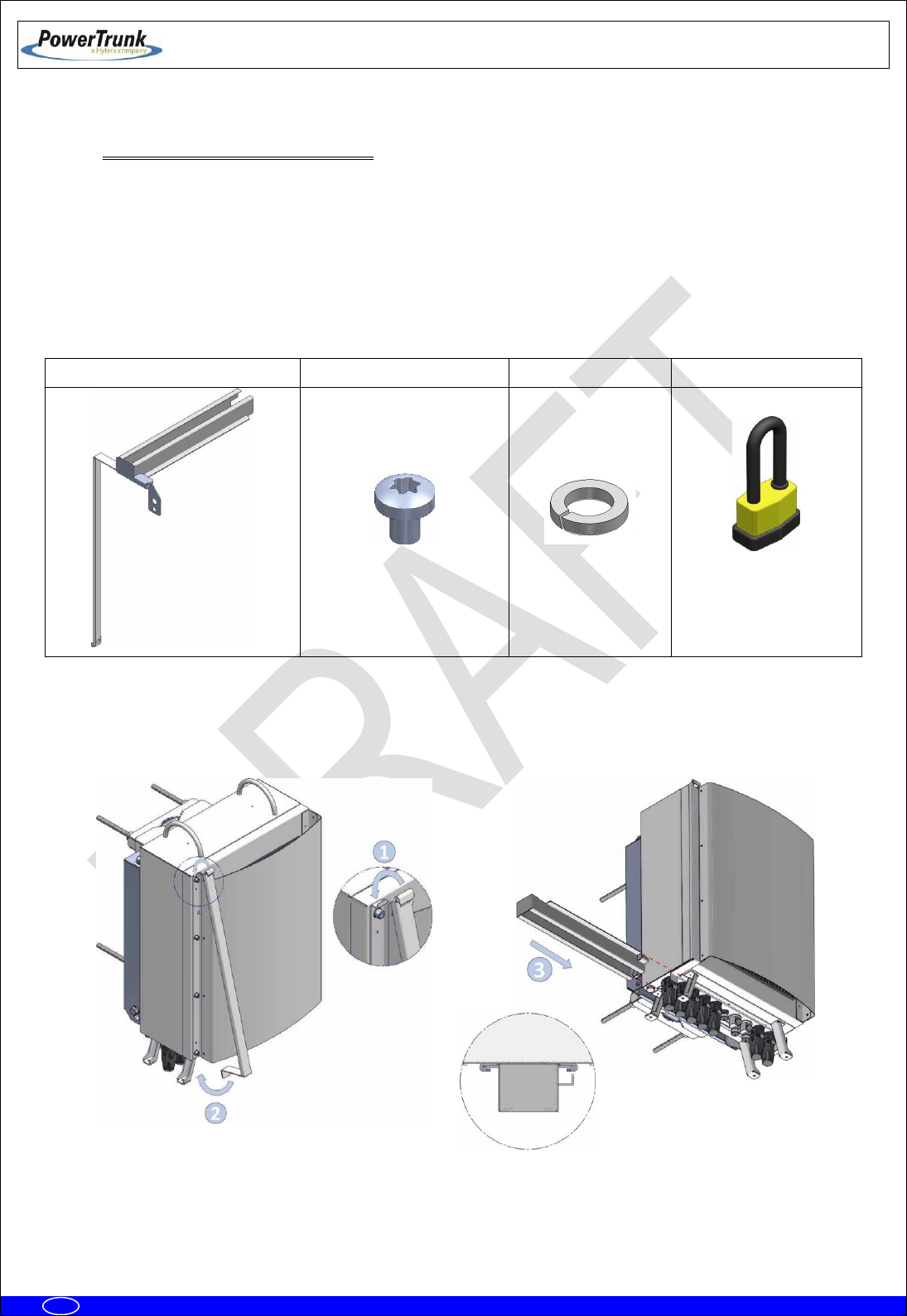
6.3.4 ANTI-VANDAL KIT INSTALLATION
The anti-vandal kit for MBS Unit is an optional accessory (D014000PT). Either the MBS Unit is
mounted on a mast/pole or on a wall, the anti-vandal kit, is performed as follows. Take into account that the
installation of the ant-vandal kit should be done once you have completed the wiring connections of the MBS
Unit.
Anti-vandal Kit:
Anti-Vandal Kit
6 x Torx screw M3X4
6 x Grower washer
1 x padlock
- Place the anti-vandal kit and slide the kit guides as shown on the following figure:
TETRA MBS UNIT. INSTALLATION GUIDE
F067646PT_2800
Page 40 of 62
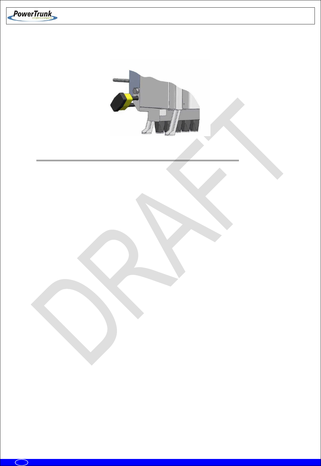
en
- Place the padlock and screw the attachment bolt to the bracket with a 17 mm wrench and 25 Nm
torque.
6.3.5 REQUIREMENTS TO CONSIDER DURING THE ANTENNA INSTALLATION
The antennas installation always will depend on TX frequencies assigned to each MBS Units that are part of
a MBS.
As a general rule, the frequencies assigned to the MBS Units of each MBS shall comply with the following
restrictions:
Sub-band.
When the MBS Units belong to the same band, these must belong to the same sub-band. Otherwise, the
duplexer TX and RX filters do not provide the necessary insulation. For example, you should not combine a
MBS Unit with 390-395 MHz TX subband with another with 395-400 MHz TX subband.
Frequency spacing:
∆f ≠ DS/n
∆f ≠ DS/n ± 25 KHz
If DS/n is not a multiple of 25 KHz, take the multiple of 25 KHz nearest lower value to DS/n and its 2 adjacent
channels (± 25 KHz).
Where:
∆f is the TX frequency spacing between the MBS Units.
DS is the duplex spacing,
n is an integer number.
If the MBS Units are combined into one antenna, will be mandatory fulfill the restrictions listed above.
If each MBS Unit has its own antenna, there are several possible cases depending on the level of
compliance with the foregoing restrictions:
TETRA MBS UNIT. INSTALLATION GUIDE
F067646PT_2800
Page 41 of 62
en
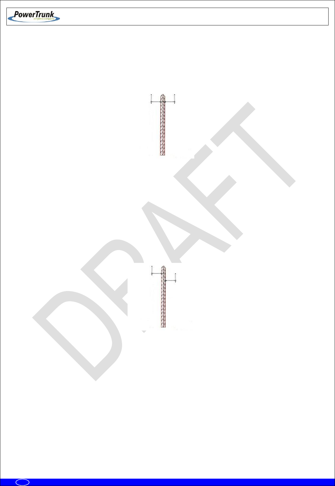
- Case 1: All MBS Units in the MBS comply with the restrictions about subband and frequency separation. In
this case, is allowed to install all the antennas in the same horizontal plane following the guidelines normally
applied for SBS sites about the horizontal distance between each antenna and the mast.
- Case 2: The restrictions about subband and frequency separation are not complied between the MBS Units
in the same MBS. In this case, the antennas installation should be done keeping an enough vertical
separation between each antenna of MBS in order to obtain the necessary isolation to avoid, when all MBS
Units are transmitting, an increase in the RSSI level respect to the level measured when the MBS Units are
not transmitting.
This option is not advisable, especially if the tower which antennas will be installed is not elevated over the
ground, because may be differences of coverage between the upper antenna and the lowest that could
affect the communications performance.

TETRA MBS UNIT. INSTALLATION GUIDE
F067646PT_2800
Page 42 of 62
en
6.3.6 CONNECTIONS
This section shows the connections to be made and the characteristics of the material to be used.
The MBS Unit is a weather-protected device once the equipment has been installed in its final location; make
sure that there is no MBS Unit connector without plug or cable connected. Besides, the external wiring
connections of the MBS Unit must be protected from weather, (vulcanizable tape can be used if it is
necessary).
To connect two MBS Units you must have the interconnection kit for additional carrier (Cod.
D014001PT). This is obtained as an independent accessory. In the following table is showed the connection
between two MBS Unit using the interconnection kit
Connections
MBS_1 connector
MBS_2 connector
Power Supply
Power_OUT
Power_IN
Ethernet
ETH
ETH
Synchronism
SYNC_OUT
SYNC_IN
Diversity in reception
DIV_OUT
DIV_IN
DIV_IN
DIV_OUT

TETRA MBS UNIT. INSTALLATION GUIDE
F067646PT_2800
Page 43 of 62
en
6.3.6.1 SUPPORTED CONFIGURATIONS
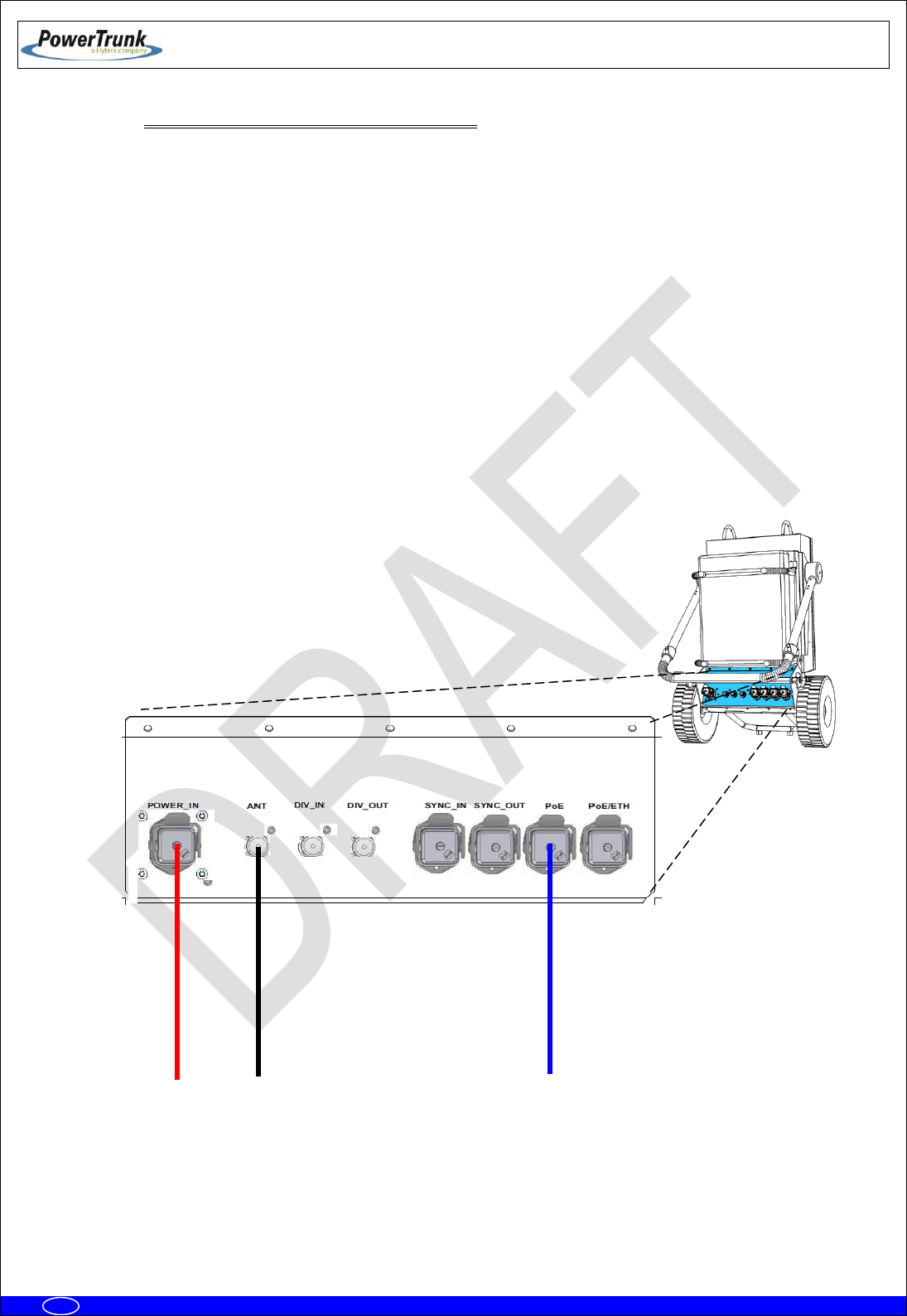
6.3.6.1.1 ONE MBS UNIT WITH DIVERSITY 1 IN RECEPTION
The connections are the following ones:
Power supply 220/110 VAC or 24 VDC.
From ANT connector to the antenna.
Connection with radio link through PoE or PoE/ETH connector (if the MBS Unit has SNI IP
option these connectors are Layer 3).
Maintenance through ETH connector (Layer 2).
Of
ANT
DIV_IN
DIV_OUT
POWER_IN
PoE/ETH
SYNC_OUT
POWER_OUT
PoE
ETH
SYNC_IN
Radio link
Antenna 1 (Tx/Rx)
Power Input
TETRA MBS UNIT. INSTALLATION GUIDE
F067646PT_2800
Page 44 of 62
en
6.3.6.1.1.1 CONFIGURATION WITH PBS ACCESSORY
The connections are the following ones:
Power supply 220/110 VAC or 24 VDC.
From ANT connector to the antenna.
Connection with radio link through PoE or PoE/ETH connector (if the MBS Unit has SNI IP
option these connectors are Layer 3).
Connection with the NMS Server-Client Rugged Laptop through the PoE/ETH connector
(Only in Isolated Operation Mode)
Note: The connection with the NMS Server-Client Rugged Laptop in the PoE/ETH connector depends of the
network topology and just applies in Isolated Operation Mode of the MBS Unit.
Radio Link 1
Antenna 1 (Tx/Rx)
Power Input
TETRA MBS UNIT. INSTALLATION GUIDE
F067646PT_2800
Page 45 of 62
en
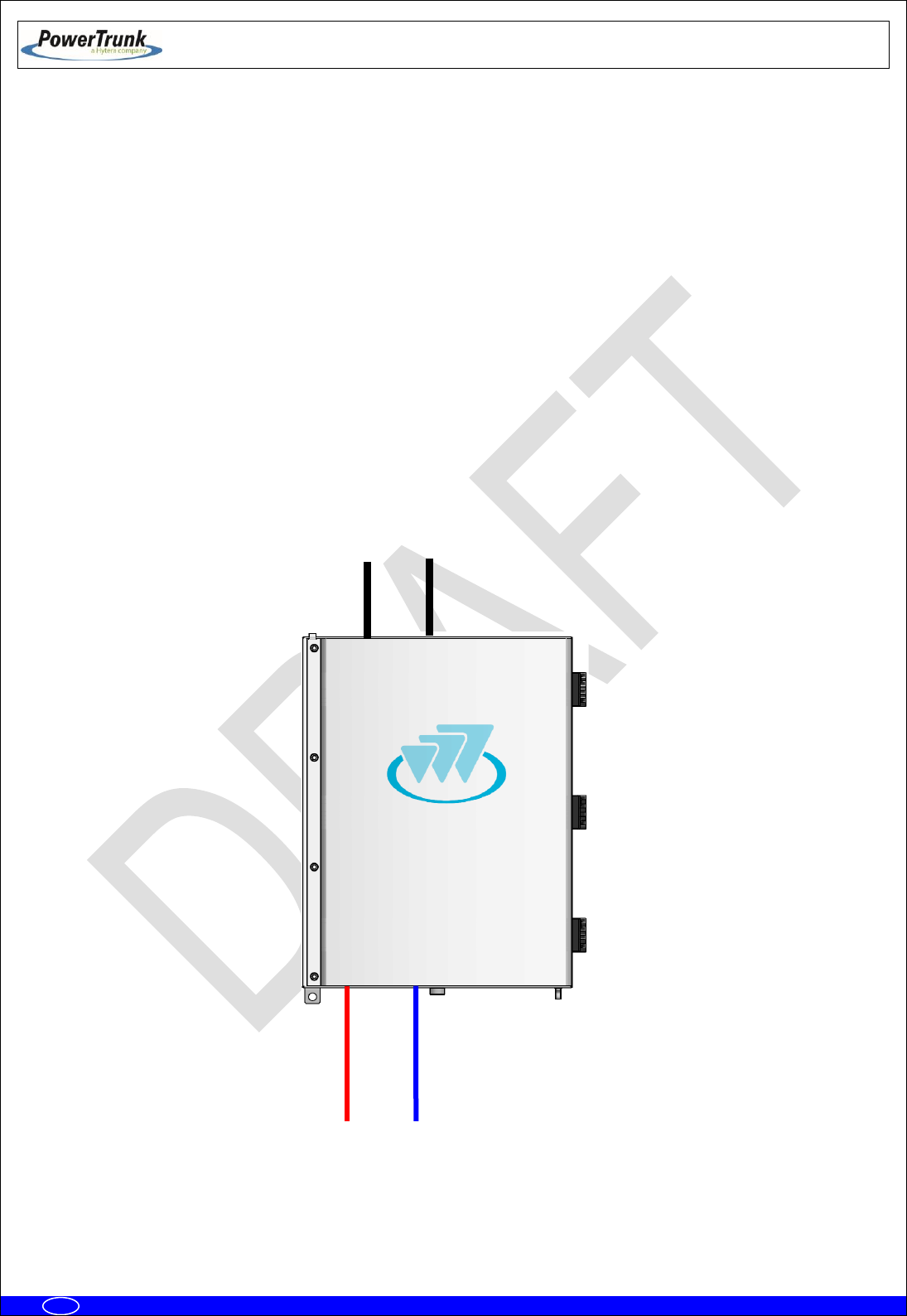
6.3.6.1.2 ONE MBS UNIT WITH DIVERSITY 2 IN RECEPTION
The connections are the following ones:
Power supply: 220/110 VAC ó 24 VDC.
From ANT connector to the first antenna.
From DIV IN connector to the second antenna.
Connection with radio link through PoE or PoE/ETH connector (if the MBS Unit has SNI IP
option these connectors are Layer 3).
Maintenance through ETH connector (Layer 2).
ANT
DIV_IN
DIV_OUT
POWER_IN
PoE/ETH
SYNC_OUT
POWER_OUT
PoE
ETH
SYNC_IN
Power
Radio link
Antenna 2 (Rx2)
Antenna 1 (Tx/Rx1)

TETRA MBS UNIT. INSTALLATION GUIDE
F067646PT_2800
Page 46 of 62
en
6.3.6.1.2.1 CONFIGURATION WITH PBS ACCESSORY
The connections are the following ones:
Power supply: 220/110 VAC ó 24 VDC.
From ANT connector to the first antenna.
From DIV IN connector to the second antenna.
Connection with radio link through PoE or PoE/ETH connector (if the MBS Unit has SNI IP
option these connectors are Layer 3).
Connection with the NMS Server-Client Rugged Laptop through the PoE/ETH connector
(Only in Isolated Operation Mode)
Note: The connection with the NMS Server-Client Rugged Laptop in the PoE/ETH connector depends of the
network topology and just applies in Isolated Operation Mode of the MBS Unit.
Radio Link 1
Antenna 1 (Tx/Rx1)
Antenna 2 (Rx2)
Power Input
TETRA MBS UNIT. INSTALLATION GUIDE
F067646PT_2800
Page 47 of 62
en
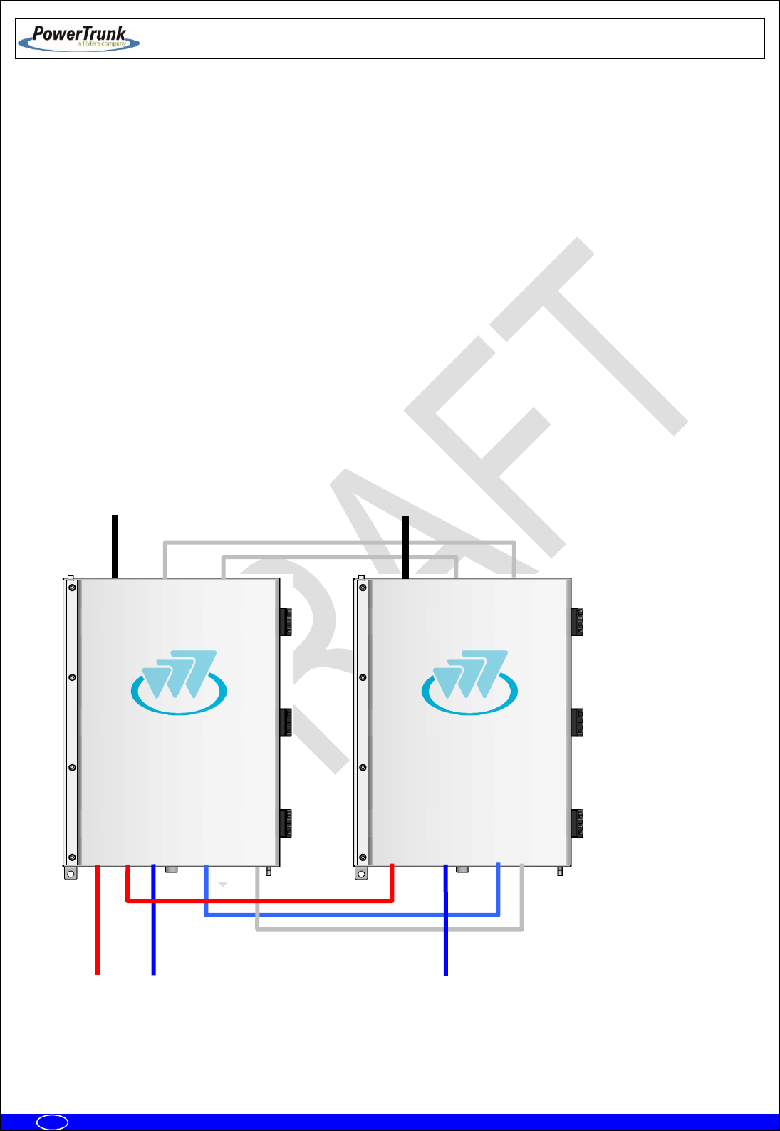
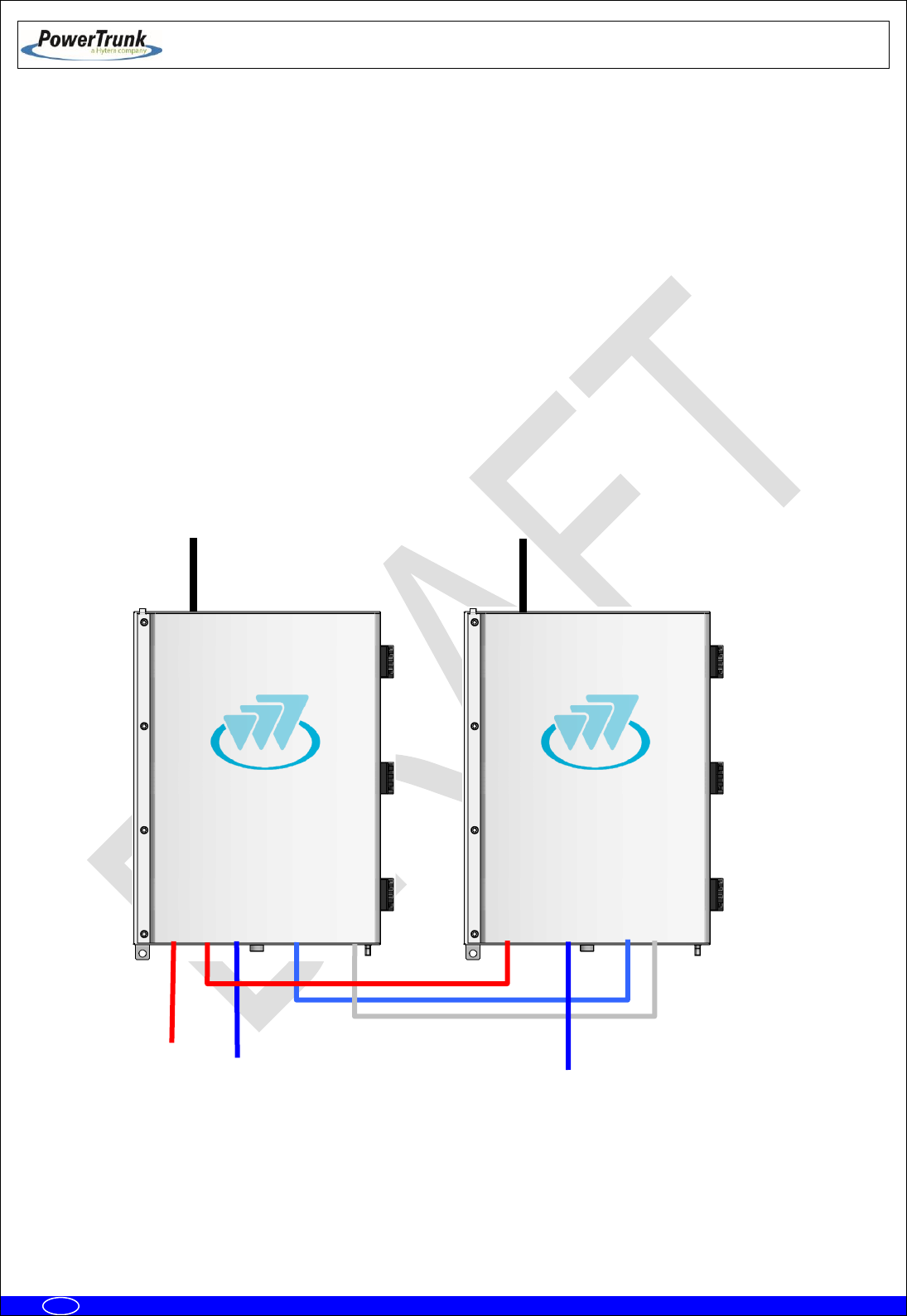
6.3.6.1.3 TWO MBS UNIT (SAME SUBBAND) WITH DIVERSITY 1 OR 2 IN RECEPTION
NOTE: Diversity 1 or 2 mode can be selected from the NMS client.
The connections are the following ones:
Power supply for the MBS Unit 1: 220/110 VAC or 24 VDC.
From ANT connector of the MBS Unit 1 to the first antenna.
From ANT connector of the MBS Unit 2 to the second antenna.
Connection with radio link through PoE connector (if the MBS Unit has SNI IP option this
connectors is Layer 3).
Maintenance through PoE/ETH connector (if the MBS Unit has SNI IP option this connector
is Layer 3 otherwise is Layer 2).
Power
Radio link_2
Radio link_1
ANT
DIV_IN
DIV_OUT
POWER_IN
PoE/ETH
SYNC_OUT
POWER_OUT
PoE
ETH
SYNC_IN
Antenna 2 (TX F2/Rx2)
Antenna 1 (TxF1/Rx1)
TX F1: Transmission Output Frequency 1
TX F2: Transmission Output Frequency 2
RX1: Reception Chain 1 of Frequency 1 and
Reception Chain 2 of Frequency 2
RX2: Recepetion Chain 2 of Frequency 1 and
Reception Chain 1 of Frequency 2
ANT
DIV_IN
DIV_OUT
POWER_IN
PoE/ETH
SYNC_OUT
POWER_OUT
PoE
ETH
SYNC_IN
TETRA MBS UNIT. INSTALLATION GUIDE
F067646PT_2800
Page 48 of 62
en
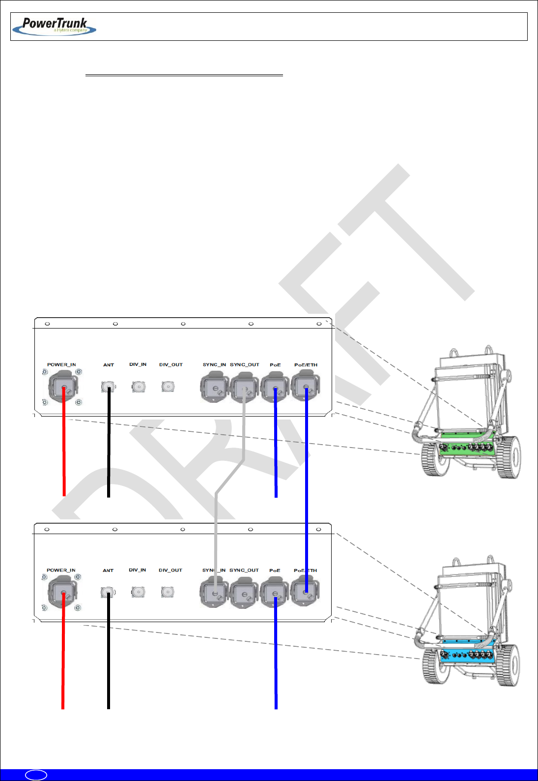
6.3.6.1.3.1 CONFIGURATION WITH PBS ACCESSORY
NOTE: Diversity 1 or 2 mode can be selected from the NMS client.
The connections are the following ones:
Power supply for the PBS Accessories 1 and 2: 220/110 VAC or 24 VDC.
From ANT connector of the PBS Accessory 1 to the first antenna.
From ANT connector of the PBS Accessory 2 to the second antenna.
Connection with radio link through PoE connector.
Note 1: The connection with the NMS Server-Client Rugged Laptop in the PoE connector depends of the
network topology and just applies in Isolated Operation Mode of the MBS Unit.
Note 2: The use of the PBS accessory for two MBS Units with SNI IP option is not supported.
PBS #1
Power Input
Antenna 1 (TxF1/Rx1)
Power Input
Radio Link 2
Radio Link 1
Antenna 2(TX F2/Rx1)
TX F1: Transmission Output Frequency 1
TX F2: Transmission Output Frequency 2
RX1: Reception Chain 1 of Frequency 1 and
Reception Chain 2 of Frequency 2
RX2: Reception Chain 2 of Frequency 1 and
Reception Chain 1 of Frequency 2
TETRA MBS UNIT. INSTALLATION GUIDE
F067646PT_2800
Page 49 of 62
en
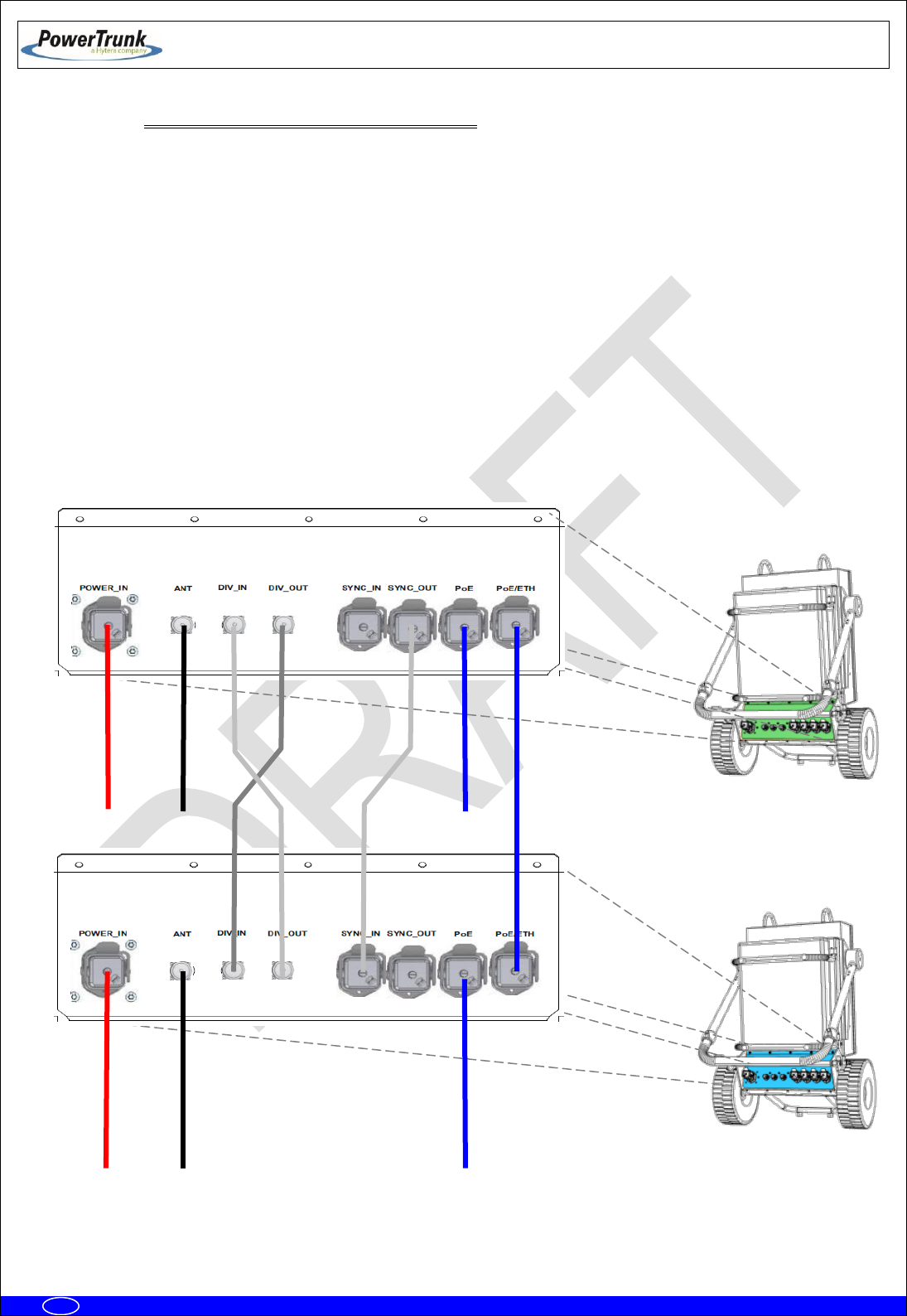
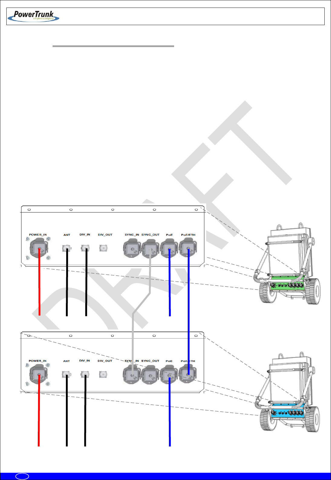
6.3.6.1.4 TWO MBS UNITS (DIFFERENT SUBBANDS) WITH DIVERSITY 1 IN RECEPTION
The connections are the following ones:
Power supply for the MBS Unit 1: 220/110 VAC or 24 VDC.
From ANT connector of the MBS Unit 1 to the antenna 1.
From ANT connector of the MBS Unit 2 to the antenna 2.
Connection with radio link through PoE connector (if the MBS Unit has SNI IP option this
connector is Layer 3).
Maintenance through PoE/ETH connector (if the MBS Unit has SNI IP option this connector
is Layer 3 otherwise is Layer 2)
Power
Radio
link 2
Radio
link 1
ANT
DIV_IN
DIV_OUT
POWER_IN
PoE/ETH
SYNC_OUT
POWER_OUT
PoE
ETH
SYNC_IN
Antenna 2
(TX F2/Rx1)
Antenna 1
(TxF1/Rx1)
TX F1: Transmission Output Frequency 1
TX F2: Transmission Output Frequency 2
RX1: Reception Chain 1 of Frequency 1 and 2
ANT
DIV_IN
DIV_OUT
POWER_IN
PoE/ETH
SYNC_OUT
POWER_OUT
PoE
ETH
SYNC_IN
PBS #2
TETRA MBS UNIT. INSTALLATION GUIDE
F067646PT_2800
Page 50 of 62
en
6.3.6.1.4.1 CONFIGURATION WITH PBS ACCESSORY
The connections are the following ones:
Power supply for the PBS Accessories 1 and 2: 220/110 VAC or 24 VDC.
From ANT connector of the PBS Accessory 1 to the antenna 1.
From ANT connector of the PBS Accessory 2 to the antenna 2.
Connection with radio link through PoE connector (if the MBS Unit has SNI IP option this
connector is Layer 3).
Maintenance through PoE connector.
Note 1: The connection with the NMS Server-Client Rugged Laptop in the PoE connector depends of the
network topology and just applies in Isolated Operation Mode of the MBS Unit.
Note 2: The use of the PBS accessory for two MBS Units with SNI IP option is not supported.
PBS #1
Power Input
Antenna 1 (TxF1/Rx1)
Power Input
Radio Link 2
Radio Link 1
Antenna2 (TX F2/Rx1)
TX F1: Transmission Output Frequency 1
TX F2: Transmission Output Frequency 2
RX1: Reception Chain 1 of Frequency 1 and 2
PBS #2

TETRA MBS UNIT. INSTALLATION GUIDE
F067646PT_2800
Page 51 of 62
en
6.3.6.1.5 TWO MBS UNITS (DIFFERENT SUBBANDS) WITH DIVERSITY 2 IN RECEPTION
The connections are the following ones:
Power supply for the MBS Unit 1: 220/110 VAC or 24 VDC.
From ANT connector of the MBS Unit 1 to the antenna 1.
From DIV IN connector of the MBS Unit 1 to the antenna 2.
From ANT connector of the MBS Unit 2 to the antenna 3.
From DIV IN connector of the MBS Unit 2 to the antenna 4.
Connection with radio link through PoE connector (if the MBS Unit has SNI IP option this
connector is Layer 3).
Maintenance through PoE/ETH connector (if the MBS Unit has SNI IP option this connector
is Layer 3 otherwise is Layer 2)
TX F1: Transmission Output Frequency 1
TX F2: Transmission Output Frequency 2
RX1: Reception Chain 1 of Frequencies 1 and 2
RX2: Reception Chain 2 of Frequencies 1 and 2
Power
Radio
link 2
Radio
link 1
ANT
DIV_IN
DIV_OUT
POWER_IN
PoE/ETH
SYNC_OUT
POWER_OUT
PoE
ETH
SYNC_IN
Antenna 3
(TX F2/Rx1)
Antenna 1
(TxF1/Rx1)
ANT
DIV_IN
DIV_OUT
POWER_IN
PoE/ETH
SYNC_OUT
POWER_OUT
PoE
ETH
SYNC_IN
Antenna 2
(Rx2)
Antenna 4
(Rx2)
TETRA MBS UNIT. INSTALLATION GUIDE
F067646PT_2800
Page 52 of 62
en
6.3.6.1.5.1 CONFIGURATION WITH PBS ACCESSORY
The connections are the following ones:
Power supply for the PBS Accessories 1 and 2: 220/110 VAC or 24 VDC.
From ANT connector of the PBS Accessory 1 to the antenna 1.
From DIV IN connector of the PBS Accessory 1 to the antenna 2.
From ANT connector of the PBS Accessory 2 to the antenna 3.
From DIV IN connector of the PBS Accessory 2 to the antenna 4.
Connection with radio link through PoE connector (if the MBS Unit has SNI IP option this
connector is Layer 3).
Maintenance through PoE/ETH connector.
Note 1: The connection with the NMS Server-Client Rugged Laptop in the PoE connector depends of the
network topology and just applies in Isolated Operation Mode of the MBS Unit.
Note 2: The use of the PBS accessory for two MBS Units with SNI IP option is not supported.
Radio Link 2
Radio Link 1
Power Input
Power Input
Antenna 1 (TxF1/Rx1)
Antenna 2 (Rx2)
Antenna 3 (TX F2/Rx1)
Antenna 4 (Rx2)
TX F1: Transmission Output Frequency 1
TX F2: Transmission Output Frequency 2
RX1: Reception Chain 1 of Frequencies 1 and 2
RX2: Reception Chain 2 of Frequencies 1 and 2
PBS #2
PBS #1
TETRA MBS UNIT. INSTALLATION GUIDE
F067646PT_2800
Page 53 of 62
en
6.3.6.2 CONNECTION OF THE EXTERNAL POWER SUPPLY
Check that the power supply source and/or the battery to be used are adapted to the
type of MBS Unit (AC/DC) and meets the voltage and current requirements
necessary to supply the equipment.
MBS Unit with AC power supply source:
- Nominal voltage: 110/220 VAC (Range: from 94 to 264 VAC).
- Use the power cable connector provided with the MBS Unit to connect the MBS Unit to
the power supply source. Use a cable of 3 wires; with weather protection; with the
following features:
Cable diameter: 5 mm – 12 mm.
Cable section: 2.5 mm2 (AWG 13) (0.6/1KV)
UL VW-1 certified power supply cable is needed.
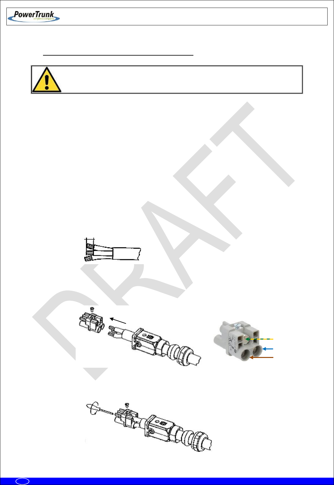
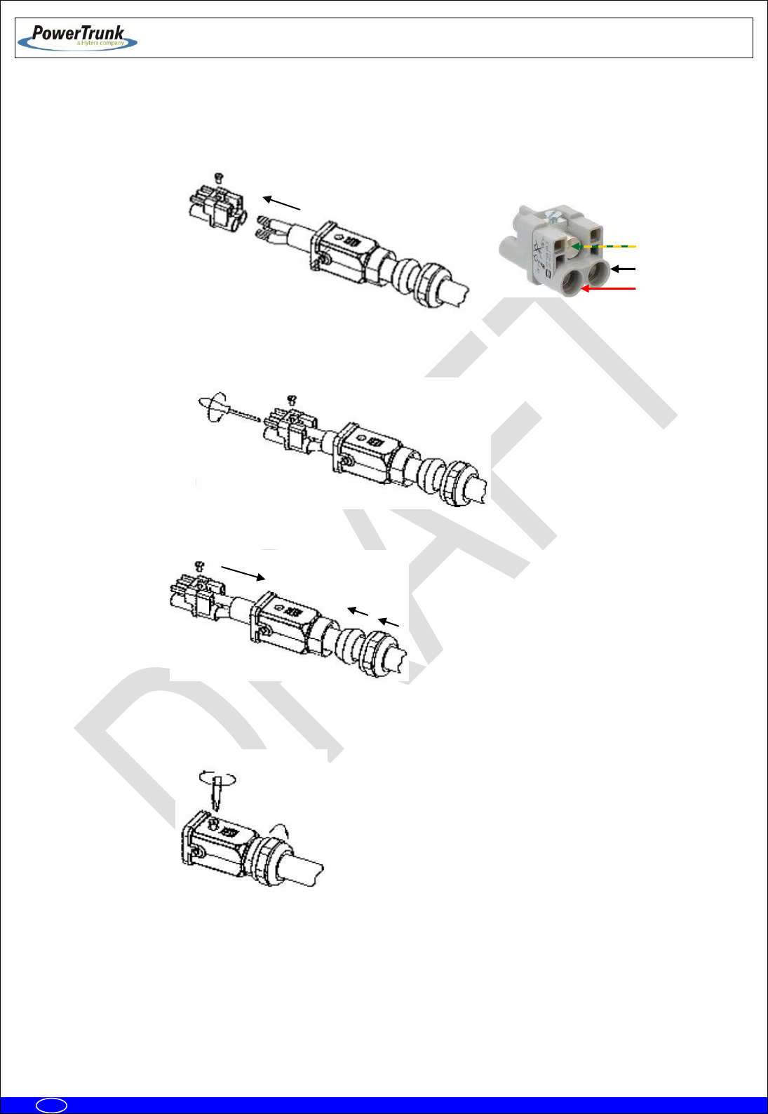
- Ensure that the connection is made in the correct way (Line, Neutral and Earth) following
the next steps:
o Strip cable and wires (stripping length 8 mm – 9 mm).
NOTE: The earth cable must be 2 mm longer.
o Push the cable through the cable gland and the hood/housing and insert the wires
into the insert respecting the correct polarity.
o Fix each wire tightening each pin from the front side with a hexagonal screwdriver
(Allen number 2).
8-9 mm
Neutral (N)
Line (L)
Earth (PE)
TETRA MBS UNIT. INSTALLATION GUIDE
F067646PT_2800
Page 54 of 62
en
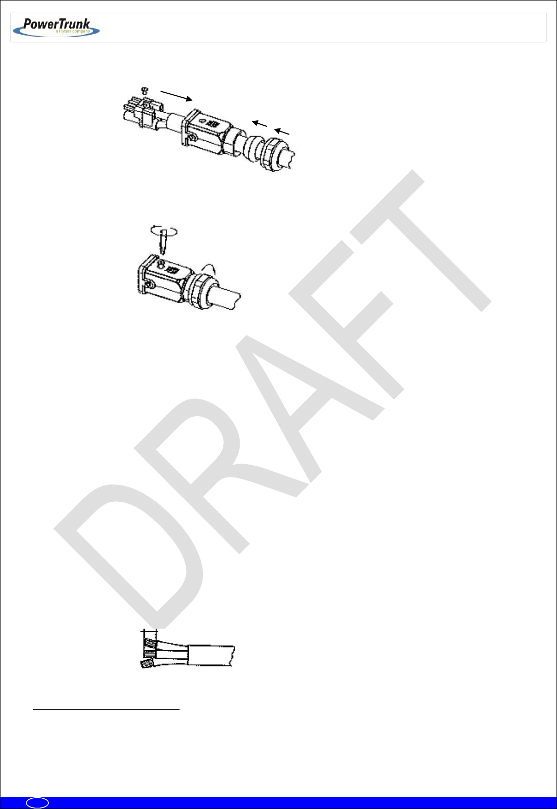
o Push the insert back into the hood/housing.
o Fix the assembly tightening the top locking screw and tightening the cable gland nut
on the back of the hood/housing.
MBS Unit with DC power supply source:
- Nominal voltage: 24 VDC (Range: from 21.6 to 31.2 VDC).
- Use the power cable connector provided with the MBS Unit to connect the MBS Unit to
the power supply source. Use a cable of 3 wires with weather protection and the
following features:
Cable diameter: 10 mm – 14 mm.
Cable section: 6 mm2 (AWG 9) (0.6/1KV).
Maximum cable length
1
:
One MBS Unit: 85 m
Two MBS Units: 42 m
UL VW-1 certified power supply cable is needed
- Ensure that the connection is made in the correct way (Positive, Negative and Earth)
following the next steps:
o Strip cable and wires (stripping length 8 mm – 9 mm).
NOTE: The Earth cable must be 2 mm longer.
1
The greater the cable length, the greater the voltage drop in it. The specified length has been calculated to ensure minimum
operating voltage of the MBS Unit, assuming a minimum voltage of 24V at the output of the power system and a typical resistivity of
copper wire ≤ 0.0172 Ω mm2/m
8-9 mm
TETRA MBS UNIT. INSTALLATION GUIDE
F067646PT_2800
Page 55 of 62
en
o Push the cable through the cable gland and the hood/housing and insert the wires
into the insert respecting the correct polarity.
o Fix each wire tightening each pin from the front side with a hexagonal screwdriver
(Allen number 2).
o Push the insert back into the hood/housing.
o Fix the assembly tightening the top locking screw and tightening the cable gland nut
on the back of the hood/housing.
Negative (-)
Positive (+)
Earth (PE)

TETRA MBS UNIT. INSTALLATION GUIDE
F067646PT_2800
Page 56 of 62
en
In both cases:
The power supply cable to the MBS Unit must be provided by the installer with the proper
power supply connector adapted for the connection to the electrical network or to a 24 VDC
source.
Ensure that the earth connection is made before equipment’s start-up. The MBS Unit has an
earth connector; this connector will connect to the earth protection of the installation, which
is different to the earth protection of the lightning rod.
Make this connection with a cable of, at least, 25 mm2 (AWG 3) section
NEVER use a gas or electricity conduit as an earth.
6.3.6.3 ANTENNA CONNECTION
With every MBS Unit, a RF super-flexible wire, N-Male – N-Male, is supplied to connect the
ANT connector of the MBS Unit with the RF wire of the antenna.
Note: In case of installation a MBS Unit with diversity 2, it is recommended to contact your
supplier and/or installer who will provide the additional RF super-flexible wire (Cod. 208931).
The RF assembly depends on the cable type used in the installation up to the antenna.
The RF cable must have a protection against water entry (vulcanizable tape).
Choose the most adaptable antenna for the installation. The antenna must have an
impedance of 50 ohms to the equipment transmission frequency. Install the antenna in
accordance with the manufacturer’s instructions.
Use a coaxial cable, avoiding as much as possible large cable lengths. Cable impedance is
50 ohms.
In installations with diversity, the greatest gain is achieved by placing the antennas on the
same horizontal plane with a minimum distance of 5.5 m between them.
Measure the ROE of the installation. Never accept a ROE greater than 2
TETRA MBS UNIT. INSTALLATION GUIDE
F067646PT_2800
Page 57 of 62
en
6.3.6.4 EXTERNAL ETHERNET CONNECTION
The Ethernet cable connector, to connect the MBS Unit with the radio link (PoE), is supplied
with every MBS Unit.
Note: In the case of connection to two radio links, it is recommended to contact your supplier
and/or installer who will provide the additional Ethernet cable connector.
The Ethernet wire for the radio link connections is supplied by the installer, and must have
the following characteristics:
Cable with 8 wires, SF/UTP cat5E with outdoor protection.
Diameter: 6.5 mm to 9.5 mm.
Maximum length: 100 m
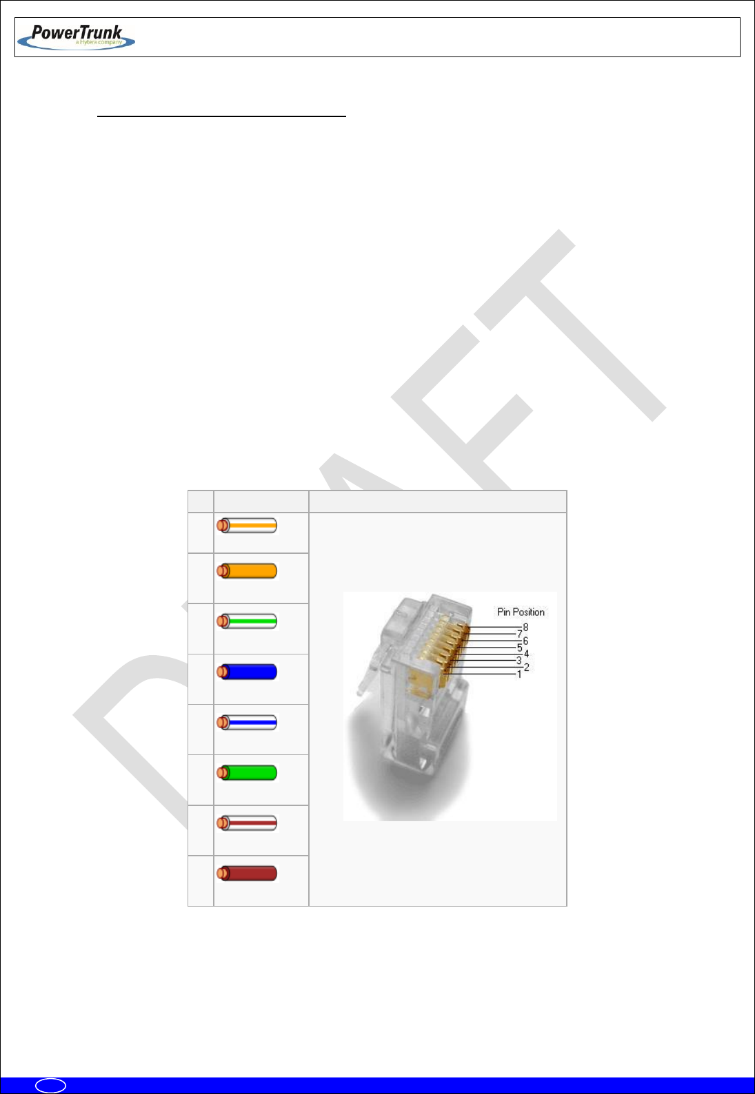
Mount the wire on the connector according to the TIA / EIA 568B standard (The
assembly requires no tools, is done manually).
Pin
Color T568B
Pins on plug face (socket is reversed)
1
White/Orange
2
Orange
3
White/Green
4
Blue
5
White/Blue
6
Green
7
White/Brown)
8
Brown

TETRA MBS UNIT. INSTALLATION GUIDE
F067646PT_2800
Page 58 of 62
en
6.3.7 CONNECTING / DISCONNECTING THE MBS AC MAINS SUPPLY
The electrical supply to the MBS is connected through a connector with a three-wire cable.
This cable shall be connected to the electrical supply network, which must comply with the standards
and/or regulations of the country in which the MBS is installed.
The connection of the MBS to the electrical installation must be carried out by specialised personnel.
The maximum current required by the MBS is 1 A at 220-240 V AC or 2 A at 100-130 V AC
The electrical installation to which the MBS is connected must comply with the current standards for
electrical installations in the country in which the MBS is installed. The nominal phase current of the MBS is 2
A at 110 V AC and 1 A at 220 V AC
The MBS requires the following external protection devices:
1. A 2-pole overcurrent protection device rated 1 A for 230 VAC power supply or 2 A for 110 VAC
power supply (when two MBS Units are supplied using the same overcurrent protection device,
the ratings will be 2 A for 230 VAC or 4 A for 110 VAC). This device shall be in accordance with
the country regulations.
Only for USA and Canada: this over-current protection device shall be UL listed and CSA
certified.
2. Earth leakage protection using a residual current device with a sensitivity of 30 mA.
The MBS must be connected to earth as described in this Installation Guide.
The MBS can be disconnected by unplugging the aerial power connector, after disconnecting the
aerial power supply connector.

TETRA MBS UNIT. INSTALLATION GUIDE
F067646PT_2800
Page 59 of 62
en
6.3.8 CONNECTING / DISCONNECTING THE MBS FROM THE DC SUPPLY
The electrical supply to the MBS is connected through a connector with a three-wire cable.
This cable shall be connected to the 24 VDC supply, which must comply with the regulations of the
country in which the MBS is installed.
The connection of the MBS to the supply must be carried out by specialised personnel.
The maximum current required by the MBS is 9 A.
The MBS requires a 2-pole external overcurrent protection devices rated 9 A (when two MBS Units
are supplied using the same overcurrent protection device, the rating will be 18 A). This device shall be in
accordance with the country regulations.
Only for USA and Canada: this over-current protection device shall be UL listed and CSA certified.
The MBS must be connected to earth as described in this Installation Guide.
The MBS can be disconnected by unplugging the power connector after disconnecting the power
supply.

TETRA MBS UNIT. INSTALLATION GUIDE
F067646PT_2800
Page 60 of 62
en
7. START UP/CONFIGURATION/VERIFICATION
IMPORTANT: Ensure that the power supply of the MBS Unit is the proper one
before switch it on; an erroneous power supply can cause damages in the
equipment.
Every MBS Unit has in its labelling the diverse options that it offers. If the MBS Unit
includes the option O148017PT, this it will have to be powered with AC (220/110
VAC), however, if the MBS Unit includes the option O148018PT it will have to be
powerred with +24 VDC nominal voltage.
Preliminary considerations for carrying out the MBS Unit start up:
- To start up the equipment, this must have the final IP correctly configured (see chapter of
infrastructure configuration (F067220PT) in the Technical Manual).
- Refer to the radio link used to configure this device. Make sure this element is properly
connected to ground.
The steps to perform the final settings are:
1.
Before connecting power supply to the MBS Unit, make sure the right voltage level reaches the
power supply cable connector.
2.
Provide power to the MBS Units through the POWER_IN connector.
3.
Wait for the MBS Unit initialization (about 3 minutes).
4.
Verify that you have access to the MBS (by performing a "ping"). Make partial checks in case of no
response from the MBS, perform pings to intermediate elements: SNI Node radio link remote
site radio link MBS.
5.
From NMS, register the MBS Unit(s), completing the necessary settings (see chapter of
infrastructure configuration, F067220PT, and the client's user manual NMS, F067201PT).
6.
Verify the absence of alarms in monitoring module and check with a radio terminal that it is
registered and you can make and receive calls. In case of interference or coverage fault alarms see
chapter of the infrastructure adjustment (F067218PT).
TETRA MBS UNIT. INSTALLATION GUIDE
F067646PT_2800
Page 61 of 62
en
8. INCIDENTS
The MBS Unit must be repaired by authorized technical personnel only. There will not
be performed any repair of the MBS Unit and it will have to be sent to factory except
for the change of the pressure equalizer or the overvoltage protections.
8.1 INTERFERENCE AT MBS UNIT
This alarm is monitored in the NMS management and configuration module. See the infrastructure
event list (F067516PT).
Any interference in the MBS Unit is activated when there are a large number of consecutive
reception faults in the MBS Unit. A reception fault is considered when a level higher than the threshold for
reception of the carrier, but is not recognized as valid TETRA signal. Depending on the signal level,
interference is considered low or high. So, if the level of signal is above the threshold for reception and below
the threshold set to high interference and is not recognized as a valid sign, it will be a low interference alarm.
If the signal level is above the threshold set to high interference and is not recognized as a valid signal, the
low level alarm would disappear (if it happened) and high interference would produce.
These alarms are turned off when the interference source disappears or with any right TETRA
reception for low interference case, and with more than one consecutive right reception for high-level
interference.

TETRA MBS UNIT. INSTALLATION GUIDE
F067646PT_2800
Page 62 of 62
en
8.2 OVER VOLTAGE PROTECTION
MBS Unit has several protections against lightning and surges, in any case the action of these
protections generate an alarm in the NMS client which disappear when the protective element is replaced by
authorized technical staff.
Protection against lightning and power surges
This protection is located within the MBS Unit. It should be changed every time it breaks
even if the MBS Unit continues functioning properly. An alarm in the NMS Client is reported
showing that the replacement of this type of protection is needed.
Protection against lightning and surges in the RF connections
RF surge protection consists of replaceable Gas Discharge Tubes (GDT) located into the RF
connectors located in the bottom of the MBS. Without GDT no protection is provided and
VSWR performance is degraded.
The GTD is removable, making easy and quick replacing if it is damaged. The replacing
intervals depend mainly upon the number and the strength of the lightning impacts but as a
general rule, must be changed after that a lightning has destroyed some elements ahead
(e.g. antenna). That is why the GTD rarely must be replaced in most use cases and life
expectancy can be up to 20 years.
GDT is connected in parallel between the central conductor and the external shield. During
an overvoltage (lightning), the tube is practically shorted and avoids overvoltage input into
the MBS. When the overvoltage disappears, GTD returns to its original condition of high
insulation and is ready to operate again.
While GTD is triggered (during lightning), the MBS may appear alarmed in the NMS client
software (alarm monitoring of the system).