Teltronic U PTRNKTBSR75410 BSR75 409-430 MHz BASE STATION RADIO User Manual User and Installation Manual
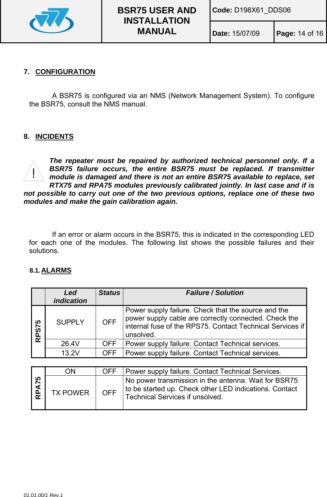
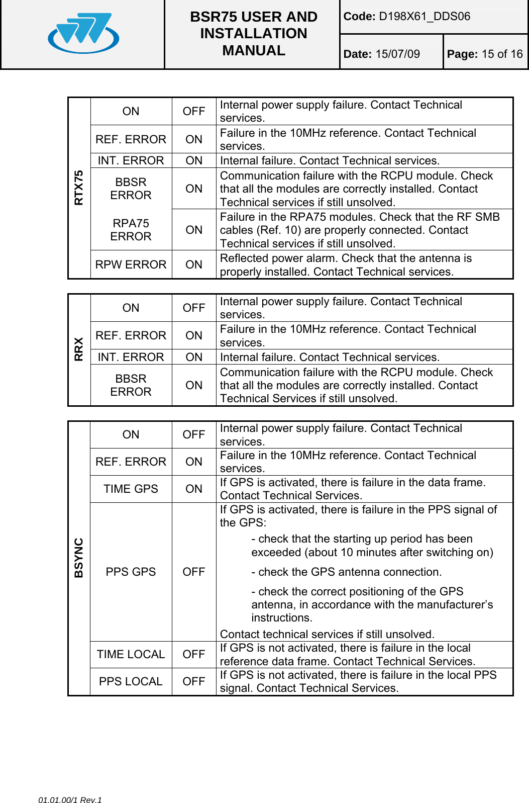
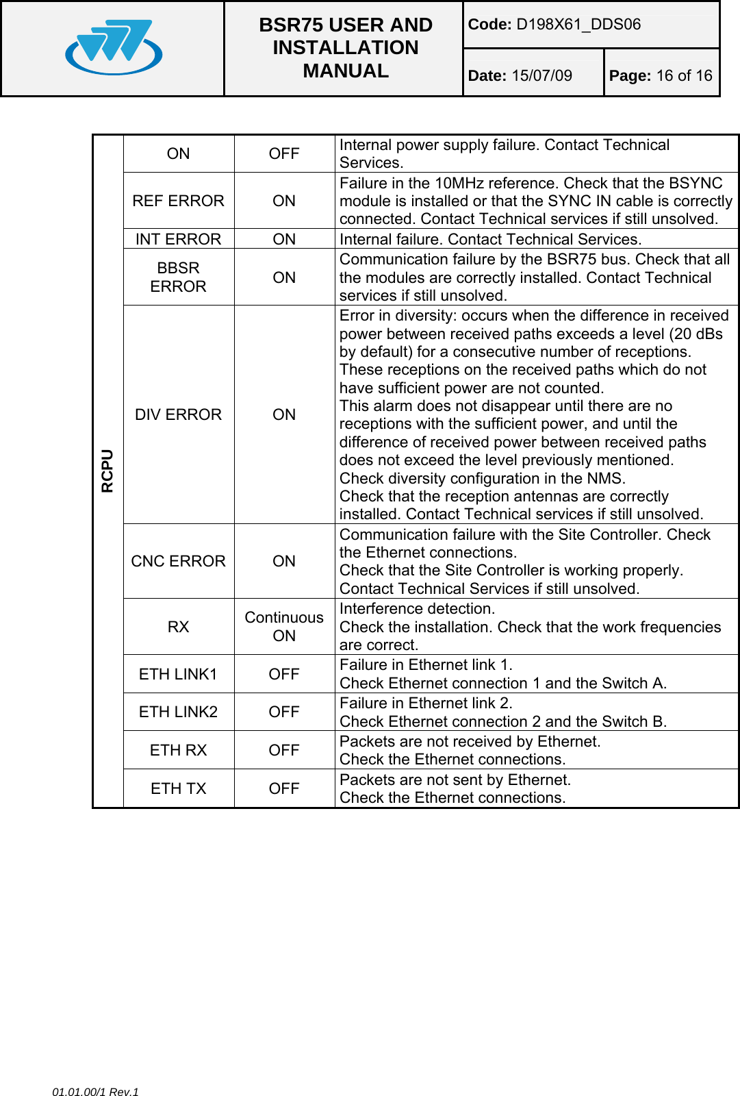
Teltronic S.A.U. BSR75 409-430 MHz BASE STATION RADIO User and Installation Manual
UserManual.wiki
>
Teltronic U
>
PTRNKTBSR75410 User Manual
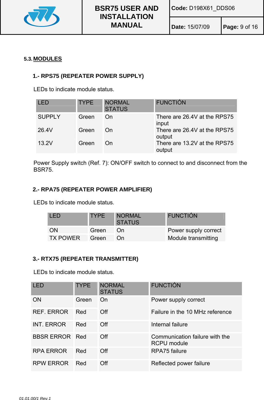
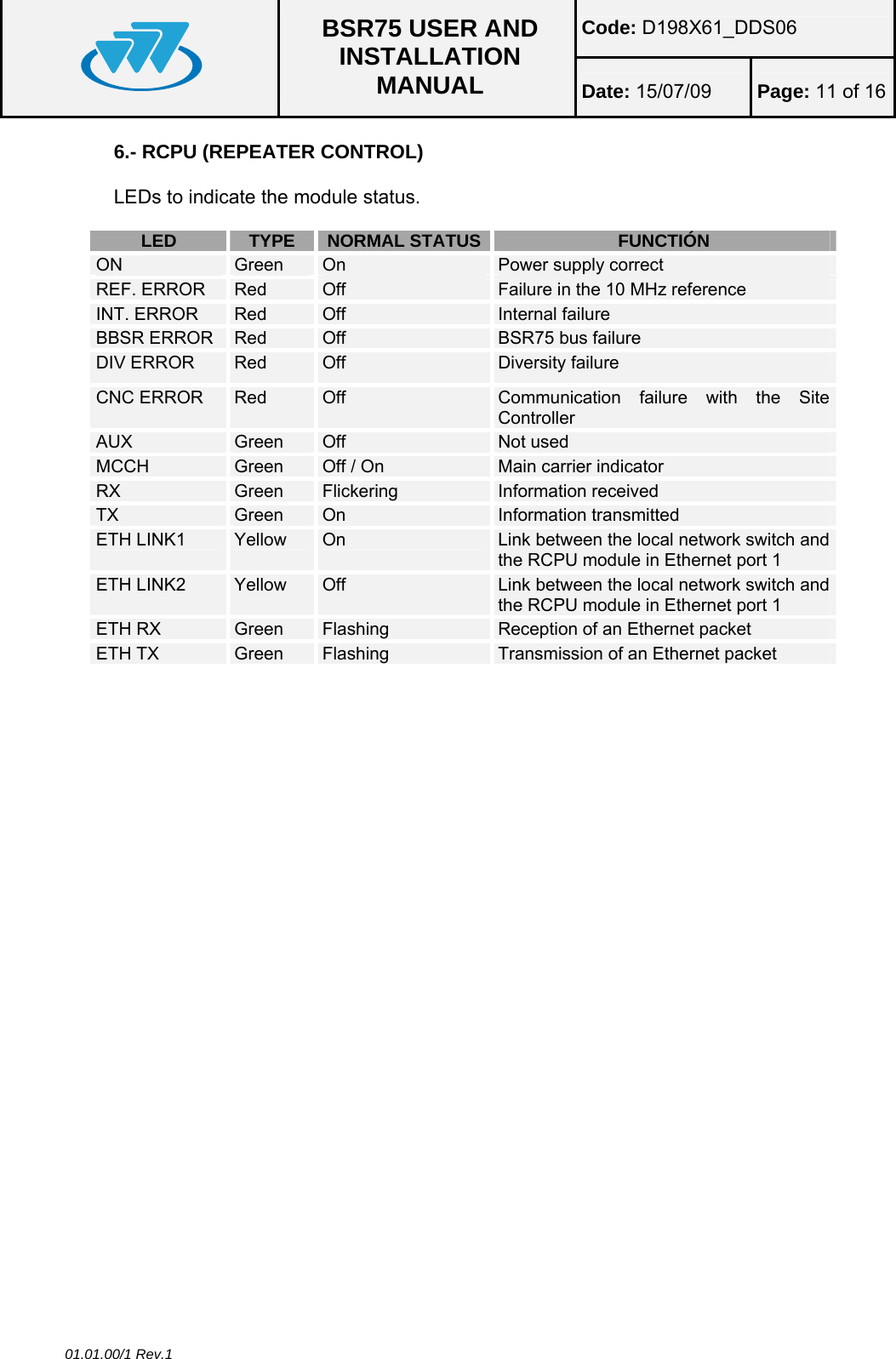
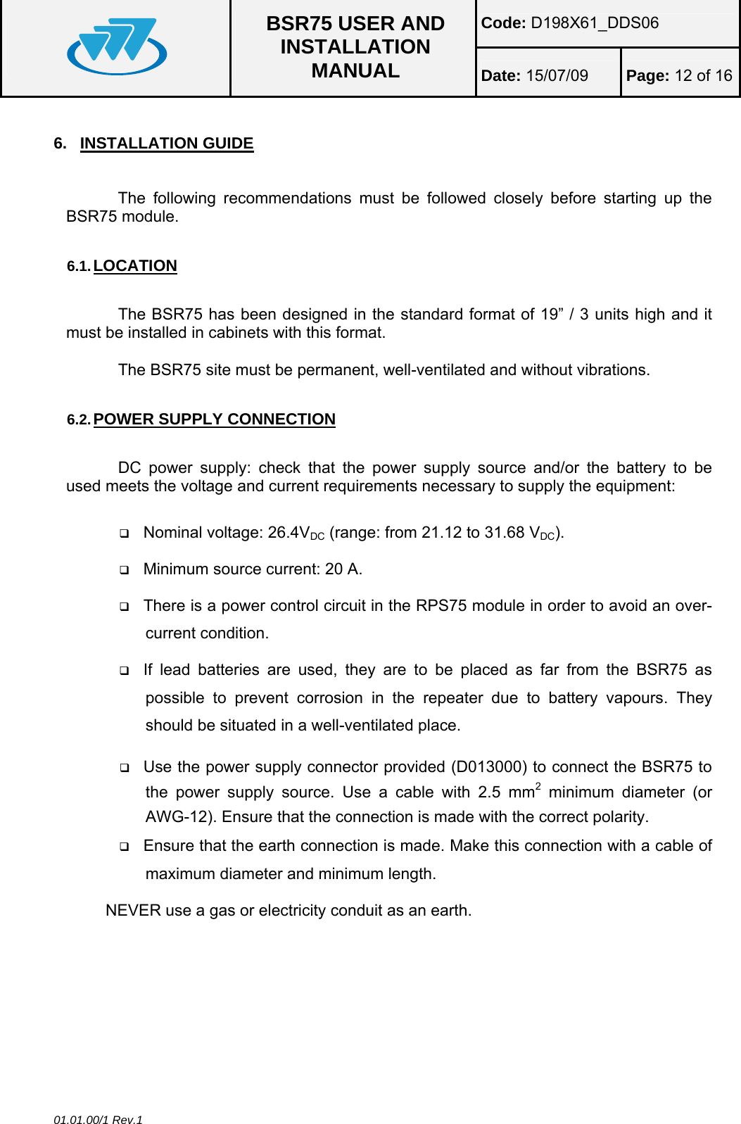
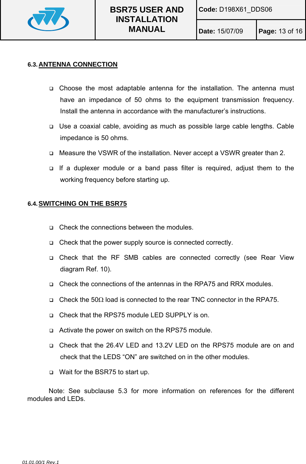
Installation Manual
Navigation menu
Upload a User Manual
Namespaces
Wiki Guide
HTML
PDF
Info
Views
User Manual
Discussion / Help
Navigation