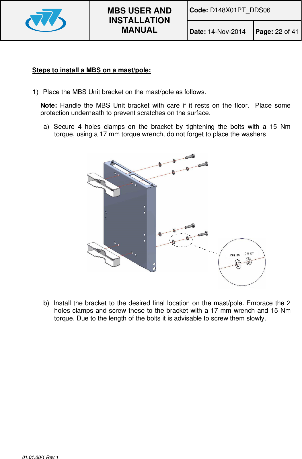
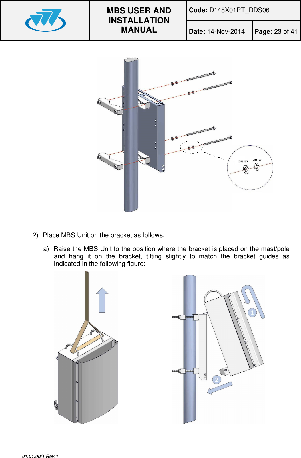
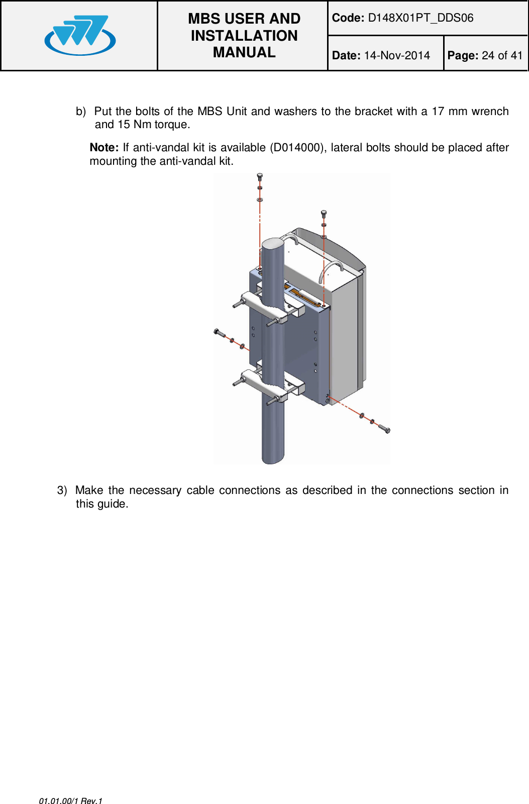
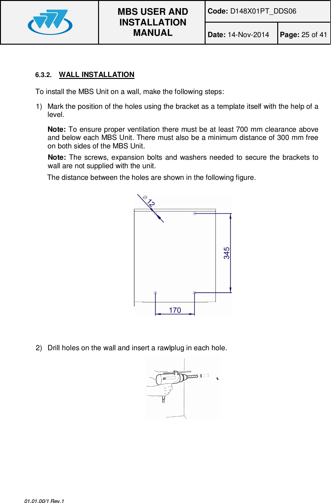
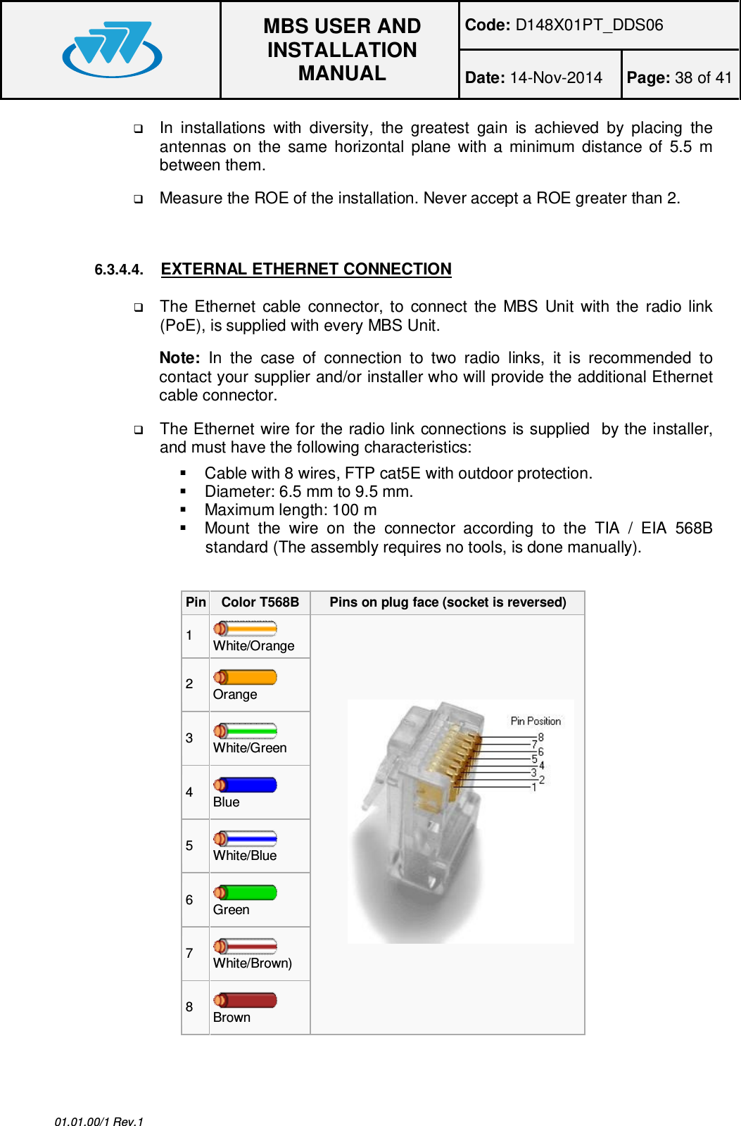
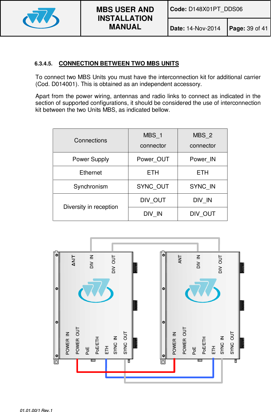
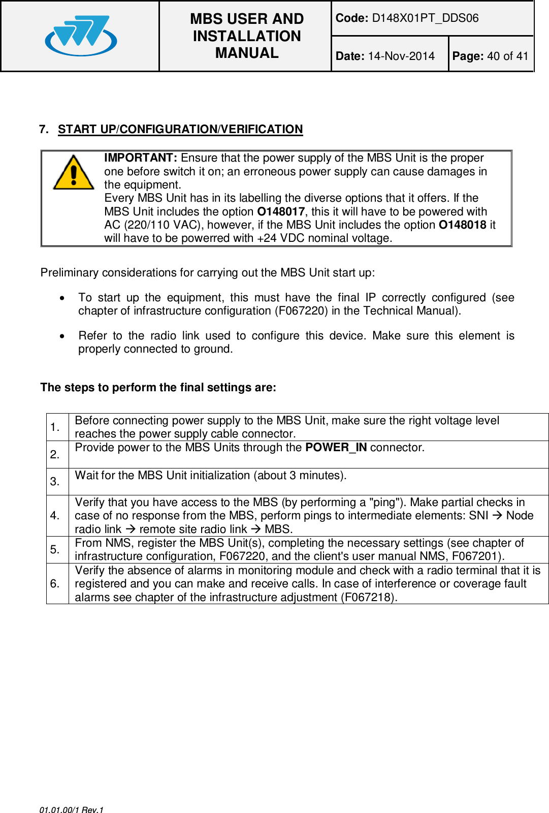
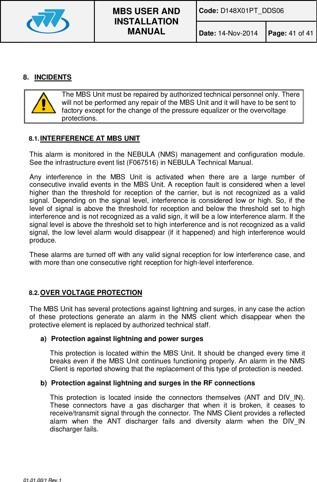
Teltronic U PTRNKTMBS760 MBS Unit -K User Manual User and Installation Manual

Teltronic S.A.U. MBS Unit -K User and Installation Manual

User manual

MBS USER AND INSTALLATION MANUAL01.01.00/1 Rev.1PRODUCT: MBSCODE: D148X01PT_DDS06VERSION: 04 REVISION: 00 DATE: 14-Nov-2014CLASSIFICATION: General information  Internal documentDOCUMENT MAINTENANCETHIS DOCUMENT HAS 17 PAGESEDIT. DATE AUTHOR DESCRIPTION1.0 05-Oct-2011 Javier Córdova First edition.2.0 02-May-2012 Javier Córdova Changes in section 4.Document code and minor editorial changes.3.0 19-Dec-2012 A. González Addition of labelling information and FCC RFExposure Requirements.4.0 14-Nov-2014 F.Rivas New chapters addedDOCUMENT APPROVALACTIVITY NAME DATE SIGNATUREPreparedRevisedProject ManagerApprovedR&D Director
MBS USER ANDINSTALLATIONMANUALCode: D148X01PT_DDS06Date: 14-Nov-2014 Page: 2 of 4101.01.00/1 Rev.1PowerTrunk Inc. is the subsidiary of Teltronic S.A.U. responsible for business development, distribution andcustomer support for Teltronic’s Land Mobile Radio products in North America. The company is headquartered inNew York City. Teltronic S.A.U. distributes the same products for Land Mobile Radio under different trademarksand brand names in other regions of the world.DisclaimerAlthough every reasonable effort has been made to ensure the accuracy of the information contained herein andany other referred document, this should not be construed as a commitment on the part of Teltronic S.A.U.and/or PowerTrunk Inc., and the liability of Teltronic S.A.U. and/or PowerTrunk Inc. for any errors and omissionsshall be limited to the correction of such errors and omissions. Teltronic S.A.U. and/or PowerTrunk Inc.welcomes any comment as a way to improve any delivered documentation.The information contained herein has been prepared for the use of appropriately trained personnel, and it isintended for the purpose of the agreement under which the information is submitted. Any party using or relyingupon this information assumes full responsibility for such use and in no event shall Teltronic S.A.U. and/orPowerTrunk Inc. be liable to anyone for especial, collateral, incidental, or consequential damages in connectionwith or arising out of the use of this information.The information or statements given in these documents regarding the suitability, capacity or performance of thementioned hardware or software products cannot be considered binding but shall be defined in the agreementmade between Teltronic S.A.U. and/or PowerTrunk Inc. and the customer.Teltronic S.A.U. and/or PowerTrunk Inc. reserves the right to revise these documents and to make changes to itscontent at any time, without prior notification.CopyrightsNo part of the information contained herein and the other referred documents may be copied, distributed ortransmitted by any means to any other party without prior written permission of Teltronic S.A.U. and/orPowerTrunk Inc. The distribution of this document may be also covered by NDA (non-disclosure agreement)between Teltronic S.A.U. and/or PowerTrunk Inc. and the receiver.Please also note that part of these contents even may be covered by patent rights.This document, the referred documents and the described product are considered protected by copyrightaccording to the applicable laws.PowerTrunk and the PowerTrunk logo are registered trademarks of Teltronic S.A.U.Copyright © PowerTrunk Inc. All rights reserved
MBS USER ANDINSTALLATIONMANUALCode: D148X01PT_DDS06Date: 14-Nov-2014 Page: 3 of 4101.01.00/1 Rev.1CONTENTS:1. INTRODUCTION ......................................................................................................... 42. UNPACKING AND CHECKING .................................................................................. 43. PREVIOUS CONSIDERATIONS................................................................................. 44. LABELLING AND INFORMATION ON SAFETY AND ELECTROMAGNETICCOMPATIBILITY .................................................................................................................. 54.1. STANDARDS  .......................................................................................................... 74.2. UL / SAFETY CERTIFICATIONS ............................................................................ 84.3. MECHANICAL AND ENVIRONMENTAL STANDARDS ......................................... 84.3.1. STANDARDS  CENELEC ................................................................................... 84.3.2. STANDARDS MIL-STD 810G ............................................................................ 95. EQUIPMENT  DESCRIPTION .................................................................................... 115.1. VIEW...................................................................................................................... 115.2. CONNECTORS ..................................................................................................... 125.3. VISUAL  INDICATORS ........................................................................................... 135.4. DIMENSIONS ........................................................................................................ 146. INSTALLATION  GUIDE ............................................................................................ 146.1. NECESSARY EQUIPMENT ................................................................................... 166.2. BASIC PRE-CONFIGURATION ............................................................................ 186.3. INST ALL ATION ..................................................................................................... 196.3.1. MAST/POLE  INSTALLATION .......................................................................... 206.3.2. WALL INSTALLATION .................................................................................... 256.3.3. ANTI-VANDAL KIT INSTALLATION ................................................................ 286.3.4. CONNECTIONS .............................................................................................. 307. START UP/CONFIGURATION/VERIFICATION ....................................................... 408. INCIDENTS ............................................................................................................... 418.1. INTERFERENCE AT MBS UNIT ........................................................................... 418.2. OVER VOLTAGE PROTECTION .......................................................................... 41
MBS USER ANDINSTALLATIONMANUALCode: D148X01PT_DDS06Date: 14-Nov-2014 Page: 4 of 4101.01.00/1 Rev.11. INTRODUCTIONThe MBS Units are the outdoor modules that make up a Mast Mounted Base Station (MBS).They are independent units that can be interconnected with each other to increase the basestation capacity. A MBS consists of a maximum of two MBS Units.This manual is common to all the equipment models, including all their options andaccessories.The proper operation of any electronic device depends on its correct use. Therefore, it isrecommended to follow the instructions showed in this manual.2.  UNPACKING AND CHECKINGThe equipment is supplied with all the necessary materials for the installation, either on amast/pole or on a wall:qMBS Unit includes the followings items§  One power connector.§  One Ethernet connector§  RF super-flexible wire N-Male – N-Male.qBrackets for the installation.Besides, in some types of installation, as detailed below, it is necessary an additionalmaterial that is NOT supplied with the equipment.IMPORTANT: If any of the necessary elements to carry out the installation processdescribed in this guide is missing or damaged, please contact your supplier.3.  PREVIOUS CONSIDERATIONSThis manual contains information about instructions for installation, maintenance and use.Read the following pages before using this equipment.It is not advisable to switch on the equipment without having previously connected theantenna otherwise irreparable damage could be. It is important to use an antenna adjustedto the work frequency.
MBS USER ANDINSTALLATIONMANUALCode: D148X01PT_DDS06Date: 14-Nov-2014 Page: 5 of 4101.01.00/1 Rev.14.  LABELLING AND INFORMATION ON SAFETY AND ELECTROMAGNETICCOMPATIBILITYThe equipment is supplied with an identification label where the model, the ICCertificate number and the FCC ID are displayed depending on the frequency work band.The equipment has been designed to fulfil the applicable compliance regulations.The equipment complies with the applicable Parts of the FCC Title 47 of the Code ofFederal Regulations and Industry Canada (IC) RSS-119 Standard.This device complies with part 15 of the FCC Rules and Industry Canada ICES-003.Operation is subject to the following two conditions: (1) this device may not causeinterference, and (2) this device must accept any interference, including interference thatmay cause undesired operation of the device.Changes or modifications not expressly approved by the party responsible forcompliance could void the user's authority to operate the equipment.RF Exposure Requirements:CAUTION:The antenna(s) used for this transmitter must not be co-located or operating inconjunction with any other antenna or transmitter.Antennas used for this transmitter must not exceed an antenna gain of 20 dBi andbe located at least 400 cm, away from any person(s) in order to comply with the FCC andIC RF exposure requirements.Failure to observe these restrictions will result in exceeding the RF exposure limits.
MBS USER ANDINSTALLATIONMANUALCode: D148X01PT_DDS06Date: 14-Nov-2014 Page: 6 of 4101.01.00/1 Rev.1The following labels will be placed in conspicuous view on the MBS Unit:qMost electronic equipment is susceptible to electromagneticinterference if it is not duly protected. If the MBS Unit is placed nearunprotected electronic devices, they may malfunction.qThe MBS Unit must not transmit without its antenna connected.qWhen installing the antenna, follow the guidelines for exposure of thehuman body to high and low frequency electromagnetic fields. Followthe supplier’s / manufacturer’s instructions.qBurns may be suffered if the antenna connector output is touched bybare skin when the MBS Unit is transmitting with the antennadisconnected.qTake care when handling the MBS Unit. It has edges, which may cut ifhandled incorrectly.qMaintenance and repair of these repeaters must be carried out byqualified personnel only.
MBS USER ANDINSTALLATIONMANUALCode: D148X01PT_DDS06Date: 14-Nov-2014 Page: 7 of 4101.01.00/1 Rev.14.1.STANDARDSThe equipment has been designed according to the following standards:ETSI EN 300 394-1 Terrestrial Trunked Radio (TETRA);Conformancetesting specification; Part 1: RadioETSI EN 301 489-1Electromagnetic Compatibility and Radio spectrumMatters (ERM); ElectroMagnetic Compatibility (EMC)standard for radio equipment and services; Part 1:Common technical requirementsETSI EN 301 489-18Electromagnetic Compatibility and Radio spectrumMatters (ERM); ElectroMagnetic Compatibility (EMC)standard for radio equipment and services; Part 18:Specific conditions for TETRA equipmentEN 60950-1 / IEC 60950-1 / UL 60950-1 /CSA 60950-1 Information technology equipment - Safety -- Part 1:General requirementsEN 60950-22 / IEC 60950-22 / UL 60950-22/ CSA 60950-22 Information technology equipment - Safety -- Part 22:Equipment to be installed outdoorsEN 60215 Safety requirements for radio transmitting equipmentEN 50383Basic standard for the calculation and measurementof electromagnetic field strength and SAR related tohuman exposure from radio base stations and fixedterminal stations for wireless telecommunicationsystems (110 MHz - 40 GHz)EN 50385Product standard to demonstrate the compliance ofradio base stations and fixed terminal stations forwireless telecommunication systems with the basicrestrictions or the reference levels related to humanexposure to radio frequency electromagnetic fields(110 MHz - 40 GHz) - General publicEN 50121-4 Railway applications - Electromagnetic compatibility -Part 4: Emission and immunity of the signalling andtelecommunications apparatusThese standards ensure the essential requirements set out in Article 3 of Directive1999/5/EC.
MBS USER ANDINSTALLATIONMANUALCode: D148X01PT_DDS06Date: 14-Nov-2014 Page: 8 of 4101.01.00/1 Rev.14.2.UL / SAFETY CERTIFICATIONSThe cabinet is UL certified, and complies with the requirements forelectronic devices to minimise risks such as fire, electric shocks or injuries to theoperator that may be caused in operation. File number is the following: E318948MBS Unit complies with the standard UL 60950-1 y UL 60950-22,including the National Differences for United States, Canada and CENELEC(Europe), and it has CB Test Certificate4.3.MECHANICAL AND ENVIRONMENTAL STANDARDSThe equipment complies with the following standards:4.3.1. STANDARDS CENELECEN 60068-2-1   * No Functional.  -40 ºC. Duration: 72 h   * Functional: -30 ºC. Duration: 16 h. Environmental testing -- Part 2-1: Tests - Test A: ColdEN 60068-2-2   * No Functional.  +85 ºC. Duration: 72 h   * Functional: +60 ºC. Duration: 16 h.Environmental testing -- Part 2-2: Tests - Test B: DryheatEN 60068-2-78   * Functional +60 ºC 93%. Duration 21days.Environmental testing -- Part 2-78: Tests - Test Cab:Damp heat, steady stateEN 60068-2-30   * Functional: 6 cycles 24 hours:       • 12 hours. Temperature: +60 ºC.Relative humidity: 95% ± 5%       • 12 hour: Temperature +25 ºC. Relativehumidity: 98% ± 5%Environmental testing -- Part 2-30: Tests - Test Db:Damp heat, cyclic (12 h + 12 h cycle)EN 60068-2-11No functional: 672 hours. +35 ºC +/- 2 ºC.5% ClNaEnvironmental testing -- Part 2: Tests - Test Ka: SaltmistEN 60529   * No functional.  IP66 Degrees of protection provided by enclosures (IPCode).EN 60068-2-9   * No functional.      • Proc. B: 20 hours of solar radiation and4 hours of darkness      • Temperature: +40 ºC      • Humidity: 65%      • Duration:  10 daysEnvironmental testing -- Part 2: Tests - Guidance forsolar radiation testing.
MBS USER ANDINSTALLATIONMANUALCode: D148X01PT_DDS06Date: 14-Nov-2014 Page: 9 of 4101.01.00/1 Rev.1EN 60068-2-64   * No functional:      • Duration: 30 minutes by axe      • 5-20 Hz. ASD: 1 m2/s3.      • 20-200 Hz.  ASD;  - 3dB/octEnvironmental testing -- Part 2-64: Tests - Test Fh:Vibration, broadband random and guidance.EN 60068-2-6   * No functional:     • Duration: 5 sweep by axe     • 5-9 Hz. Displacement 1.2 mm.     • 9-200 Hz.  Acceleration 4 m/s2Environmental testing -- Part 2-6: Tests - Test Fc:Vibration (sinusoidal).UNE-EN 60598   * Vibration type: Sine swept   * Frequency range: From 10 to 55 Hz   * Amplitude (peak):       • 10 Hz   Amplitude (peak): 1.4 mm       • 38 Hz Amplitude (peak): 20 m/s2       • 55  Hz Amplitude (peak): 20 m/s2   * Number of axes:  3 axes   * Swept ratio:  1 Oct./min.   * Duration: 30 min./axisVibration: simulation of the fixing between MBS unitand mast.Eurocode  UNE-EN  1991-1-4  * Wind speed: 200 km/h (55.55 m/s) (Safetyfactor 1.5)  * Height in post:  20 mProtection for avoiding damages either in theenclosure and the fixing parts, due to meteo effectssuch as strong gusts of wind.4.3.2. STANDARDS MIL-STD 810GMIL-STD-810G METHOD 502.5 procedure I,(C2): -40 ºC. Duration: 72 h Cold (Storage and transportation).MIL-STD-810G METHOD 502.5 procedure I,(C1): -30 ºC. Duration: 16 h Cold (Operation).MIL-STD-810G METHOD 501.5 procedure I(A1): +85ºC. Duration: 72 h Dry Heat (Storage and transportation).MIL-STD-810G METHOD 501.5 procedure I(A2): +60ºC. Duration: 16 h Dry Heat (Operation).MIL-STD-810G - Method 507.5, procedure II(Aggravated): (10 cycles, 24 hours) 30º-60ºCat 95%rH. Humidity.MIL-STD-810G - Method 509.5672 hours. +35 ºC +/- 2 ºC. 5% ClNa. Salt Fog.MIL-STD-810G - Method 505.5:-  Proc. B: 20 hours of solar radiation and4 hours of darkness-  Temperature: +40 ºC-  Humidity: 65%-  Duration:  10 daysSolar Radiation (Sunshine).
MBS USER ANDINSTALLATIONMANUALCode: D148X01PT_DDS06Date: 14-Nov-2014 Page: 10 of 4101.01.00/1 Rev.1MIL_STD-810G 514.6, Test procedure I,Category 4, table C-VI C3  (Figure 514,6 C-3) Vibration.MIL-STD-810G 516.6 Test procedure I and III,20 g 11 ms, half sinus Shock.
MBS USER ANDINSTALLATIONMANUALCode: D148X01PT_DDS06Date: 14-Nov-2014 Page: 11 of 4101.01.00/1 Rev.15.  EQUIPMENT DESCRIPTION5.1.VIEW5421312Male panel connectorFemale cable connector3
MBS USER ANDINSTALLATIONMANUALCode: D148X01PT_DDS06Date: 14-Nov-2014 Page: 12 of 4101.01.00/1 Rev.15.2.CONNECTORS·1.- Terminal with the following meaning depending on the MBS Unit Power option:- AC MBS Units:  Neutral contact (N).- DC MBS Units:  Negative contact (-).·2.- Terminal with the following meaning depending on the MBS Unit Power option:- AC MBS Units:  Line contact (L).- DC MBS Units:  Positive contact (+).·3.- Power supply Earth contact.·4.- Pressure equalizer.·5.- Chassis Earth contact.·ETH: Connector that allows Ethernet connection between MBS Units. It also can beused as Maintenance Ethernet connector.·PoE/ETH: Power Over Ethernet (IEEE 802.3at) connector. It provides power supply(48 VDC) and Ethernet connection to a PoE radio link. It can be used asMaintenance Ethernet connector if there is not radio link (Poe) connected.·PoE: Power Over Ethernet (IEEE 802.3at) connector. It provides power supply (48VDC) and Ethernet connection to a PoE radio link.·SYNC OUT: Synchronism output connector. It provides synchronism to a secondMBS Unit through its SYNC_IN connector.·SYNC IN: Synchronism input connector.·DIV OUT: Output reception connector. It provides the receiver chain 2 to the nextMBS Unit through its DIV IN connector.·DIV IN: Reception antenna connector (receiver chain 2). It is connected to anantenna or to a MBS Unit DIV OUT connector (diversity 2).·ANT: Transmission/reception antenna power connector (receiver chain 1).·POWER OUT: Output power supply connector. It provides power supply to anotherMBS Unit with the same Power Supply option.·POWER IN: Input power supply connector (VAC or VDC).
MBS USER ANDINSTALLATIONMANUALCode: D148X01PT_DDS06Date: 14-Nov-2014 Page: 13 of 4101.01.00/1 Rev.1Note:  POWER_IN and POWER_OUT connectors have a coding key to avoid wrongconnections; on the following table is showed the location of this coding key depending onthe MBS Unit power supply option.External view of power supply panel connectorAC Power Supply DC Power SupplyNote: The amount of power delivered by both PoE and PoE/ETH connectors to the radiolinks can not exceed 35 W in total.5.3.VISUAL INDICATORSA MBS Unit has a LED indicator that, depending on its state, will indicate the function of the MBS UnitThe LEDs show the MBS Unit state:LEDTYPENORMAL STATEFUNCTIÓNSTATE Tricolor Green ON / Orange ON·Green On: MBS Unit is operating andtransmitting.·Green flashing: MBS Unit initializing·Red On: There is no link with CNC and nocontrol from any LSC.·Red flashing: When MBS Unit iscontrolled by the CNC, showing any kindof alarm other than the communication oneis NOT OK.·Orange On: MBS Unit is operating andtransmitting in fallback mode.·Orange flashing:  When MBS Unit is infallback mode, showing any kind of alarmother than the communication one is NOTOK.·OFF: The equipment is either withoutpower source or is damaged.
MBS USER ANDINSTALLATIONMANUALCode: D148X01PT_DDS06Date: 14-Nov-2014 Page: 14 of 4101.01.00/1 Rev.15.4.DIMENSIONS6.  INSTALLATION GUIDEThe following recommendations must be followed before powering on the MBS Unit module.Next diagram shows the steps to be followed to carry out the installation:
MBS USER ANDINSTALLATIONMANUALCode: D148X01PT_DDS06Date: 14-Nov-2014 Page: 15 of 4101.01.00/1 Rev.1Verification of the necessaryequipmentBasic Pre-ConfigurationFinal location installationFinal Configuration/Verification
MBS USER ANDINSTALLATIONMANUALCode: D148X01PT_DDS06Date: 14-Nov-2014 Page: 16 of 4101.01.00/1 Rev.16.1.NECESSARY EQUIPMENTMake sure you have the necessary equipment depending on theconfiguration to install. If any of the elements necessary to carry out theinstallation process described in this manual, were lost or damaged, contactyour supplier and / or installer.Necessary equipmentElement Code CommentsMBS Unit D148x01 “x” varies depending on band.Each MBS Unit includes:-  MBS Unit equipment-  Power supply cable connector-  Ethernet cable connector-  RF superflexible wire N-Male ↔ N-Male-  Brackets for installationAnti-vandal kit D014000 It is only necessary if anti-vandal protection isrequiredEthernet cable connector 225120 Every MBS Unit includes one connector of thistype; if a MBS Unit must be connected to tworadio links, it is necessary to have a secondunit.RF superflexible wire N-Male↔ N-Male208931 Each MBS Unit includes one cable of this type;if a MBS Unit requires diversity 2 on reception itis necessary to have a second  unit.Additional carrierinterconnection kitD014001 It is mandatory in case of connecting a secondMBS Unit to the first MBS Unit.
MBS USER ANDINSTALLATIONMANUALCode: D148X01PT_DDS06Date: 14-Nov-2014 Page: 17 of 4101.01.00/1 Rev.1Additional equipment to be considered for installationElement CommentsCable to power the MBSUnit.See features in external power connection section. One powersupply cable connector is supplied with the MBS Unit.Ethernet cable to connectPoE radio linksSee features in Ethernet connection section. One Ethernetcable connector is supplied with the MBS Unit.Antenna coaxial cable andantenna. See features in Antenna connection section.ToolsElement CommentsToolbox In addition to the usual material used for installations(wrenches, screwdrivers ...) it is necessary to use:- Torque wrench for 17 mm hexagonal  nut capable of delivering15 Nm.- Vulcanizable tape.Ethernet Cable Cable to make specific maintenance tasks in the field
MBS USER ANDINSTALLATIONMANUALCode: D148X01PT_DDS06Date: 14-Nov-2014 Page: 18 of 4101.01.00/1 Rev.16.2.BASIC PRE-CONFIGURATIONBefore connecting the MBS Unit to the infrastructure it should have the IP addresscorrectly configured in order to have remote access once it is connected (to set the IPaddress, see the configuration chapter (F067220) in technical manual).Steps:·  Apply power supply to the MBS through its POWER_IN  connector.·  Wait 3 minutes until the MBS Unit initializes.·  Connect the PC, to set the IP address, to the ETH connector.·  Change the IP address according to the network IP addressing.·  Check that IP address was successfully changed through a “ping” from the PC to thenew IP address of the MBS Unit.
MBS USER ANDINSTALLATIONMANUALCode: D148X01PT_DDS06Date: 14-Nov-2014 Page: 19 of 4101.01.00/1 Rev.16.3.INSTALLATIONThe MBS has been designed to be mounted on both mast/pole and wall. This chapterprovides the necessary steps to be followed for a right MBS Unit installation.At least two people are required to carry out the installation of a MBS Unit on a mast/pole.Bracket system:1 x Bracket 2 x clamp (2 holes) 2 x clamp (4 holes)4 x Bolt M10x180(Clamp attachment)6 x Bolt M10x40(lateral attachment MBS-Bracket & Clamp-Bracket)2 x Bolt  M10x20(Top attachment MBS-Bracket)12 x Grower washer DIN 127Ø1012 Plain washer DIN125 xØ10---
MBS USER ANDINSTALLATIONMANUALCode: D148X01PT_DDS06Date: 14-Nov-2014 Page: 20 of 4101.01.00/1 Rev.16.3.1. MAST/POLE INSTALLATIONThe different section types of mast/pole where the MBS Unit can be mounted are thefollowing ones:qCircular section: Diameter from 30 mm to 130 mm.qSquare section: From 30 mm x30 mm to 85 mm x85 mm.qL section: From 30 mm x30 mm to 110 mm x110 mm.In the choice of the mast/pole where the MBS Unit is being installed the followingrecommendations must be followed:qThe mast/pole has to support the loads due to the installation of some elementson them.qThe mast/pole has to support the loads due to the action of the wind, snow aswell as its own weight, because these are going to induce its flexion.qThe mast/pole must have the enough inertia both lateral and frontal in order thatthe action of different loads does not induce permanent deformations on it.qThe manufacturer of the mast/pole must evaluate the structural factor of themast/pole correctly depending on its type.qIt is necessary to take into account both the height where the MBS Unit isinstalled and its weight/dimensions (See section “MBS Unit” in chapter(F067326) “SBS Technical Description” in the Technical Manual).It is recommended to choose a lattice mast/pole in case of this one has ahigh height and it is going to be submitted to important flexion efforts. In anycase, it is responsibility of the manufacturer of the mast/pole to determine ifthe resistant section of mast/pole is suitable.
MBS USER ANDINSTALLATIONMANUALCode: D148X01PT_DDS06Date: 14-Nov-2014 Page: 21 of 4101.01.00/1 Rev.1The brackets should be installed tight enough to support the MBS Unit without causingdeformation of the mast/pole or areas of corrosion.Once mounted in its definitive location, if the vandal resistant kit is available, it willprevent the access / disassembly not authorized.In case of installing more than one MBS Unit on the same mast/pole, it is recommendednot to mount one above the other one to avoid the heat transfer from the MBS Unit lowto the MBS Unit high. If the MBS Units have to be installed in the same vertical axisthese must be oriented in different directions to increase the separation of them as far aspossible, depending on the length of wiring between both equipments (1.5 mapproximately).
MBS USER ANDINSTALLATIONMANUALCode: D148X01PT_DDS06Date: 14-Nov-2014 Page: 22 of 4101.01.00/1 Rev.1Steps to install a MBS on a mast/pole:1)  Place the MBS Unit bracket on the mast/pole as follows.Note: Handle the MBS Unit bracket with care if it rests on the floor.  Place someprotection underneath to prevent scratches on the surface.a) Secure 4 holes clamps on the bracket by tightening the bolts with a 15 Nmtorque, using a 17 mm torque wrench, do not forget to place the washersb)  Install the bracket to the desired final location on the mast/pole. Embrace the 2holes clamps and screw these to the bracket with a 17 mm wrench and 15 Nmtorque. Due to the length of the bolts it is advisable to screw them slowly.
MBS USER ANDINSTALLATIONMANUALCode: D148X01PT_DDS06Date: 14-Nov-2014 Page: 23 of 4101.01.00/1 Rev.12)  Place MBS Unit on the bracket as follows.a)  Raise the MBS Unit to the position where the bracket is placed on the mast/poleand hang it on the bracket, tilting slightly to match the bracket guides asindicated in the following figure:
MBS USER ANDINSTALLATIONMANUALCode: D148X01PT_DDS06Date: 14-Nov-2014 Page: 24 of 4101.01.00/1 Rev.1b)  Put the bolts of the MBS Unit and washers to the bracket with a 17 mm wrenchand 15 Nm torque.Note: If anti-vandal kit is available (D014000), lateral bolts should be placed aftermounting the anti-vandal kit.3)  Make the necessary cable connections as described in the connections section inthis guide.
MBS USER ANDINSTALLATIONMANUALCode: D148X01PT_DDS06Date: 14-Nov-2014 Page: 25 of 4101.01.00/1 Rev.16.3.2. WALL INSTALLATIONTo install the MBS Unit on a wall, make the following steps:1)  Mark the position of the holes using the bracket as a template itself with the help of alevel.Note: To ensure proper ventilation there must be at least 700 mm clearance aboveand below each MBS Unit. There must also be a minimum distance of 300 mm freeon both sides of the MBS Unit.Note: The screws, expansion bolts and washers needed to secure the brackets towall are not supplied with the unit.The distance between the holes are shown in the following figure.2)  Drill holes on the wall and insert a rawlplug in each hole.
MBS USER ANDINSTALLATIONMANUALCode: D148X01PT_DDS06Date: 14-Nov-2014 Page: 26 of 4101.01.00/1 Rev.13)  Place the bracket over the rawlplug and insert the bolts and washers. Finally screwthem with a 17 mm wrench and 15 Nm torque.4)  Place the MBS Unit on the bracket as follows.a)  Raise the MBS Unit to the position where the bracket is placed and hang it on thebracket, tilting slightly to match the anchor guides as indicated in the followingfigure:
MBS USER ANDINSTALLATIONMANUALCode: D148X01PT_DDS06Date: 14-Nov-2014 Page: 27 of 4101.01.00/1 Rev.1b)  Put the bolts of the MBS Unit and washers to the bracket with a 17 mm wrenchand 15 Nm torque. The order is bolt + grower washer + plain washer.Note: If anti-vandal kit is available (D014000), lateral bolts should be placed aftermounting the anti-vandal kit.5)  Make the necessary cable connections as described in the connections section inthis guide.
MBS USER ANDINSTALLATIONMANUALCode: D148X01PT_DDS06Date: 14-Nov-2014 Page: 28 of 4101.01.00/1 Rev.16.3.3. ANTI-VANDAL KIT INSTALLATIONThe anti-vandal kit for MBS Unit is an optional accessory (D014000). Either the MBSUnit is mounted on a mast/pole or on a wall, the anti-vandal kit, is performed as follows.Take into account that the installation of the ant-vandal kit should be done once youhave completed the wiring connections of the MBS Unit.Anti-vandal Kit:Anti-Vandal Kit  6 x Torx screw M3X4 6  x Growerwasher1 x padlock-  Place the anti-vandal kit and slide the kit guides as shown on the following figure:
MBS USER ANDINSTALLATIONMANUALCode: D148X01PT_DDS06Date: 14-Nov-2014 Page: 29 of 4101.01.00/1 Rev.1-  Place the padlock and screw the attachment bolt to the bracket with a 17 mmwrench and 15 Nm torque.
MBS USER ANDINSTALLATIONMANUALCode: D148X01PT_DDS06Date: 14-Nov-2014 Page: 30 of 4101.01.00/1 Rev.16.3.4. CONNECTIONSThis section shows the connections to be made and the characteristics of the material tobe used. The MBS Unit is a weather-protected device once the equipment has beeninstalled in its final location; make sure that there is no MBS Unit connector without plugor cable connected. Besides, the external wiring connections of the MBS Unit must beprotected from weather, (vulcanizable tape can be used if it is necessary).
MBS USER ANDINSTALLATIONMANUALCode: D148X01PT_DDS06Date: 14-Nov-2014 Page: 31 of 4101.01.00/1 Rev.16.3.4.1. SUPPORTED CONFIGURATIONSa)  ONE MBS UNIT WITHOUT DIVERSITY IN RECEPTIONThe connections are the following ones:qPower supply 220/110 VAC or 24 VDC.qFrom ANT connector to the antenna.qConnection with radio link through PoE connector.qMaintenance through PoE/ETH N or ETH connector.OfANTDIV_INDIV_OUTPOWER_INPoE/ETHSYNC_OUTPOWER_OUTPoEETHSYNC_INRadio linkAntenna 1 (Tx/Rx)Power Input
MBS USER ANDINSTALLATIONMANUALCode: D148X01PT_DDS06Date: 14-Nov-2014 Page: 32 of 4101.01.00/1 Rev.1b)  ONE MBS UNIT WITH DIVERSITY 2 IN RECEPTIONThe connections are the following ones:qPower supply: 220/110 VAC ó 24 VDC.qFrom ANT connector to the first antenna.qFrom DIV IN connector to the second antenna.qConnection with the radio link through PoE connector.qMaintenance through PoE/ETH or ETH connector.ANTDIV_INDIV_OUTPOWER_INPoE/ETHSYNC_OUTPOWER_OUTPoEETHSYNC_INPowerRadio link Antenna 2 (Rx2)Antenna 1 (Tx/Rx1)
MBS USER ANDINSTALLATIONMANUALCode: D148X01PT_DDS06Date: 14-Nov-2014 Page: 33 of 4101.01.00/1 Rev.1c)  TWO MBS UNIT WITH DIVERSITY 2 IN RECEPTIONThe connections are the following ones:qPower supply for the MBS Unit 1: 220/110 VAC or 24 VDC.qFrom ANT connector of the MBS Unit 1 to the first antenna.qFrom ANT connector of the MBS Unit 2 to the second antenna.qConnection with the radio links through PoE connector of both MBS Units.qMaintenance through PoE/ETH connector of both MBS UnitsPowerRadio link_2Radio link_1ANTDIV_INDIV_OUTPOWER_INPoE/ETHSYNC_OUTPOWER_OUTPoEETHSYNC_INAntenna 2 (TXF2/Rx2)Antenna 1 (TxF1/Rx1)TX F1: Output Transmission Frequency 1TX F2: Output Transmission Frequency 2RX1: Reception “Chain 1” of frequencies 1 y 2RX2: “Recepetion Chain 2” of frequencies 1 y 2ANTDIV_INDIV_OUTPOWER_INPoE/ETHSYNC_OUTPOWER_OUTPoEETHSYNC_IN
MBS USER ANDINSTALLATIONMANUALCode: D148X01PT_DDS06Date: 14-Nov-2014 Page: 34 of 4101.01.00/1 Rev.16.3.4.2. CONNECTION OF THE EXTERNAL POWER SUPPLYCheck that the power supply source and/or the battery to be used areadapted to the type of MBS Unit (AC/DC) and meets the voltage and currentrequirements necessary to supply the equipment.a)  MBS Unit with AC power supply source:qNominal voltage: 110/220 VAC (Range: from 94 to 264 VAC).qUse the power cable connector provided with the MBS Unit to connect theMBS Unit to the power supply source. Use a cable of 3 wires; with weatherprotection; with the following features:§  Cable diameter: 6 mm - 12 mm.§  Cable section: 4 mm² (0.6/1KV) or AWG-11.qEnsure that the connection is made in the correct way (Line, Neutral andEarth) following the next steps:§  Strip cable and wires (stripping length 8 mm -9 mm).NOTE: The earth cable must be 2 mm longer.§  Push the cable through the cable gland and the hood/housing andinsert the wires into the insert respecting the correct polarity.8-9mmNeutral (N)Line (L)Earth (PE)
MBS USER ANDINSTALLATIONMANUALCode: D148X01PT_DDS06Date: 14-Nov-2014 Page: 35 of 4101.01.00/1 Rev.1§  Fix each wire tightening each pin from the front side with a hexagonalscrewdriver (Allen number 2).§  Push the insert back into the hood/housing.§  Fix the assembly tightening the top locking screw and tightening thecable gland nut on the back of the hood/housing.b)  MBS Unit with DC power supply source:qNominal voltage: 24 VDC (Range: from 21.6 to 31.2 VDC).qUse the power cable connector provided with the MBS Unit to connect theMBS Unit to the power supply source. Use a cable of 3 wires with weatherprotection and the following features:§  Cable diameter: 10 mm - 14 mm.§  Cable section: 6 mm² (0.6/1KV) or AWG-10.§  Maximum cable length1:-  One MBS Unit: 85 m.-  Two MBS Units: 42 m.1The greater the cable length, the greater the voltage drop in it. The specified length has been calculated to ensureminimum operating voltage of the MBS Unit, assuming a minimum voltage of 24V at the output of the power system and atypical resistivity of copper wire Ω ≤ 0.0172 mm2/m.
MBS USER ANDINSTALLATIONMANUALCode: D148X01PT_DDS06Date: 14-Nov-2014 Page: 36 of 4101.01.00/1 Rev.1qEnsure that the connection is made in the correct way (Positive, Negativeand Earth) following the next steps:§  Strip cable and wires (stripping length 8 mm - 9 mm).NOTE: The Earth cable must be 2 mm longer.§  Push the cable through the cable gland and the hood/housing andinsert the wires into the insert respecting the correct polarity.§  Fix each wire tightening each pin from the front side with a hexagonalscrewdriver (Allen number 2).§  Push the insert back into the hood/housing.8-9mmNegative (-)Positive(+)Earth (PE)
MBS USER ANDINSTALLATIONMANUALCode: D148X01PT_DDS06Date: 14-Nov-2014 Page: 37 of 4101.01.00/1 Rev.1§  Fix the assembly tightening the top locking screw and tightening thecable gland nut on the back of the hood/housing.c)  In both cases:qThe power supply cable to the MBS Unit must be provided by the installerwith the proper power supply connector adapted for the connection to theelectrical network or to a 24 VDC sourceqEnsure that the earth connection is made. The MBS Unit has an earthconnector; this connector will connect to the earth protection of theinstallation, which is different to the earth protection of the lightning rod.Make this connection with a cable of, at least, 25 mm2 section (or AWG-3).NEVER use a gas or electricity conduit as an earth.6.3.4.3. ANTENNA CONNECTIONqWith every MBS Unit, a RF super-flexible wire, N-Male – N-Male, is suppliedto connect the ANT connector of the MBS Unit with the RF wire of theantenna.Note: In case of installation a MBS Unit with diversity 2, it is recommended tocontact your supplier and/or installer who will provide the additional RFsuper-flexible wire (Cod. 208931).qThe RF assembly depends on the cable type used in the installation up to theantenna.qThe RF cable must have a protection against water entry (vulcanizable tape).qChoose the most adaptable antenna for the installation. The antenna musthave an impedance of 50 ohms to the equipment transmission frequency.Install the antenna in accordance with the manufacturer’s instructions.qUse a coaxial cable, avoiding as much as possible large cable lengths. Cableimpedance is 50 ohms.
MBS USER ANDINSTALLATIONMANUALCode: D148X01PT_DDS06Date: 14-Nov-2014 Page: 38 of 4101.01.00/1 Rev.1qIn installations with diversity, the greatest gain is achieved by placing theantennas on the same horizontal plane with a minimum distance of 5.5 mbetween them.qMeasure the ROE of the installation. Never accept a ROE greater than 2.6.3.4.4. EXTERNAL ETHERNET CONNECTIONqThe Ethernet cable connector, to connect the MBS Unit with the radio link(PoE), is supplied with every MBS Unit.Note: In the case of connection to two radio links, it is recommended tocontact your supplier and/or installer who will provide the additional Ethernetcable connector.qThe Ethernet wire for the radio link connections is supplied  by the installer,and must have the following characteristics:§  Cable with 8 wires, FTP cat5E with outdoor protection.§  Diameter: 6.5 mm to 9.5 mm.§  Maximum length: 100 m§  Mount the wire on the connector according to the TIA / EIA 568Bstandard (The assembly requires no tools, is done manually).PinColor T568BPins on plug face (socket is reversed)1White/Orange2Orange3White/Green4Blue5White/Blue6Green7White/Brown)8Brown
MBS USER ANDINSTALLATIONMANUALCode: D148X01PT_DDS06Date: 14-Nov-2014 Page: 39 of 4101.01.00/1 Rev.16.3.4.5. CONNECTION BETWEEN TWO MBS UNITSTo connect two MBS Units you must have the interconnection kit for additional carrier(Cod. D014001). This is obtained as an independent accessory.Apart from the power wiring, antennas and radio links to connect as indicated in thesection of supported configurations, it should be considered the use of interconnectionkit between the two Units MBS, as indicated bellow.Connections MBS_1connectorMBS_2connectorPower Supply Power_OUT Power_INEthernet ETH ETHSynchronism SYNC_OUT SYNC_INDiversity in reception DIV_OUT DIV_INDIV_IN DIV_OUTANTDIV_INDIV_OUTPOWER_INPoE/ETHSYNC_OUTPOWER_OUTPoEETHSYNC_INANTDIV_INDIV_OUTPOWER_INPoE/ETHSYNC_OUTPOWER_OUTPoEETHSYNC_IN
MBS USER ANDINSTALLATIONMANUALCode: D148X01PT_DDS06Date: 14-Nov-2014 Page: 40 of 4101.01.00/1 Rev.17.  START UP/CONFIGURATION/VERIFICATIONIMPORTANT:Ensure that the power supply of the MBS Unit is the properone before switch it on; an erroneous power supply can cause damages inthe equipment.Every MBS Unit has in its labelling the diverse options that it offers. If theMBS Unit includes the option O148017, this it will have to be powered withAC (220/110 VAC), however, if the MBS Unit includes the option O148018 itwill have to be powerred with +24 VDC nominal voltage.Preliminary considerations for carrying out the MBS Unit start up:·  To start up the equipment, this must have the final IP correctly configured (seechapter of infrastructure configuration (F067220) in the Technical Manual).·  Refer to the radio link used to configure this device. Make sure this element isproperly connected to ground.The steps to perform the final settings are:1. Before connecting power supply to the MBS Unit, make sure the right voltage levelreaches the power supply cable connector.2.Provide powertotheMBSUnits through thePOWER_INconnector.3. Wait for the MBS Unit initialization (about 3 minutes).4. Verify that you have access to the MBS (by performing a "ping"). Make partial checks incase of no response from the MBS, perform pings to intermediate elements: SNI à Noderadio link à remote site radio link à MBS.5. From NMS, register the MBS Unit(s), completing the necessary settings (see chapter ofinfrastructure configuration, F067220, and the client's user manual NMS, F067201).6. Verify the absence of alarms in monitoring module and check with a radio terminal that it isregistered and you can make and receive calls. In case of interference or coverage faultalarms see chapter of the infrastructure adjustment (F067218).
MBS USER ANDINSTALLATIONMANUALCode: D148X01PT_DDS06Date: 14-Nov-2014 Page: 41 of 4101.01.00/1 Rev.18. INCIDENTSThe MBS Unit must be repaired by authorized technical personnel only. Therewill not be performed any repair of the MBS Unit and it will have to be sent tofactory except for the change of the pressure equalizer or the overvoltageprotections.8.1.INTERFERENCE AT MBS UNITThis alarm is monitored in the NEBULA (NMS) management and configuration module.See the infrastructure event list (F067516) in NEBULA Technical Manual.Any interference in the MBS Unit is activated when there are a large number ofconsecutive invalid events in the MBS Unit. A reception fault is considered when a levelhigher than the threshold for reception of the carrier, but is not recognized as a validsignal. Depending on the signal level, interference is considered low or high. So, if thelevel of signal is above the threshold for reception and below the threshold set to highinterference and is not recognized as a valid sign, it will be a low interference alarm. If thesignal level is above the threshold set to high interference and is not recognized as a validsignal, the low level alarm would disappear (if it happened) and high interference wouldproduce.These alarms are turned off with any valid signal reception for low interference case, andwith more than one consecutive right reception for high-level interference.8.2.OVER VOLTAGE PROTECTIONThe MBS Unit has several protections against lightning and surges, in any case the actionof these protections generate an alarm in the NMS client which disappear when theprotective element is replaced by authorized technical staff.a)  Protection against lightning and power surgesThis protection is located within the MBS Unit. It should be changed every time itbreaks even if the MBS Unit continues functioning properly. An alarm in the NMSClient is reported showing that the replacement of this type of protection is needed.b)  Protection against lightning and surges in the RF connectionsThis protection is located inside the connectors themselves (ANT and DIV_IN).These connectors have a gas discharger that when it is broken, it ceases toreceive/transmit signal through the connector. The NMS Client provides a reflectedalarm when the ANT discharger fails and diversity alarm when the DIV_INdischarger fails.

Navigation menu