Telular 09000 Cellular Alarm Transmission System User Manual T200 T300

Telular Corporation Cellular Alarm Transmission System T200 T300

Contents

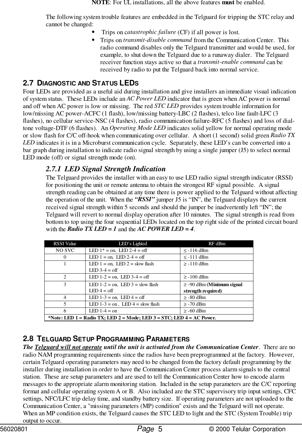
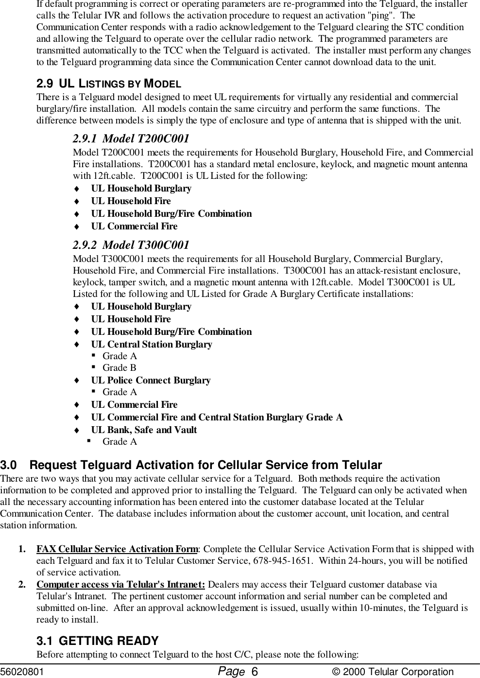
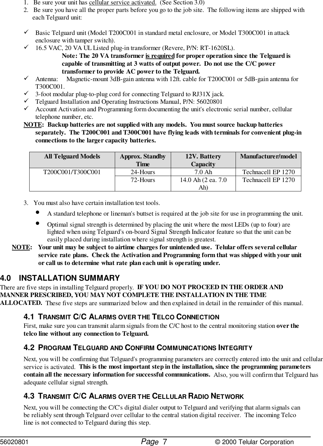
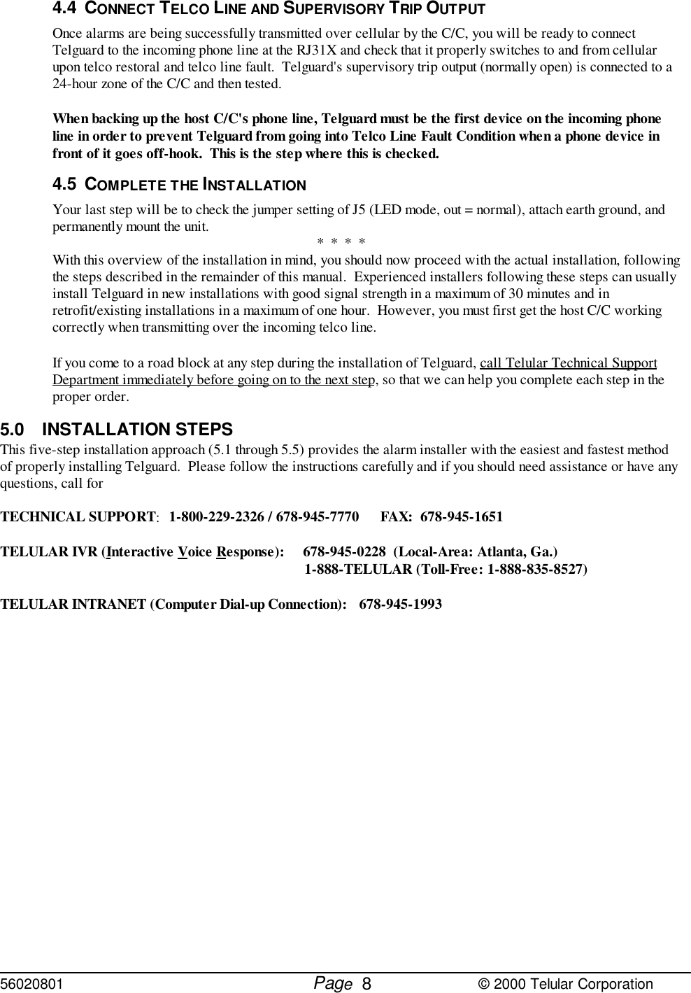
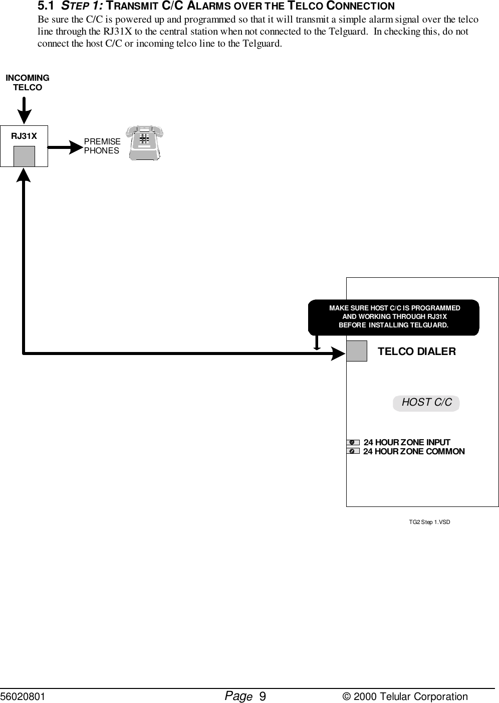
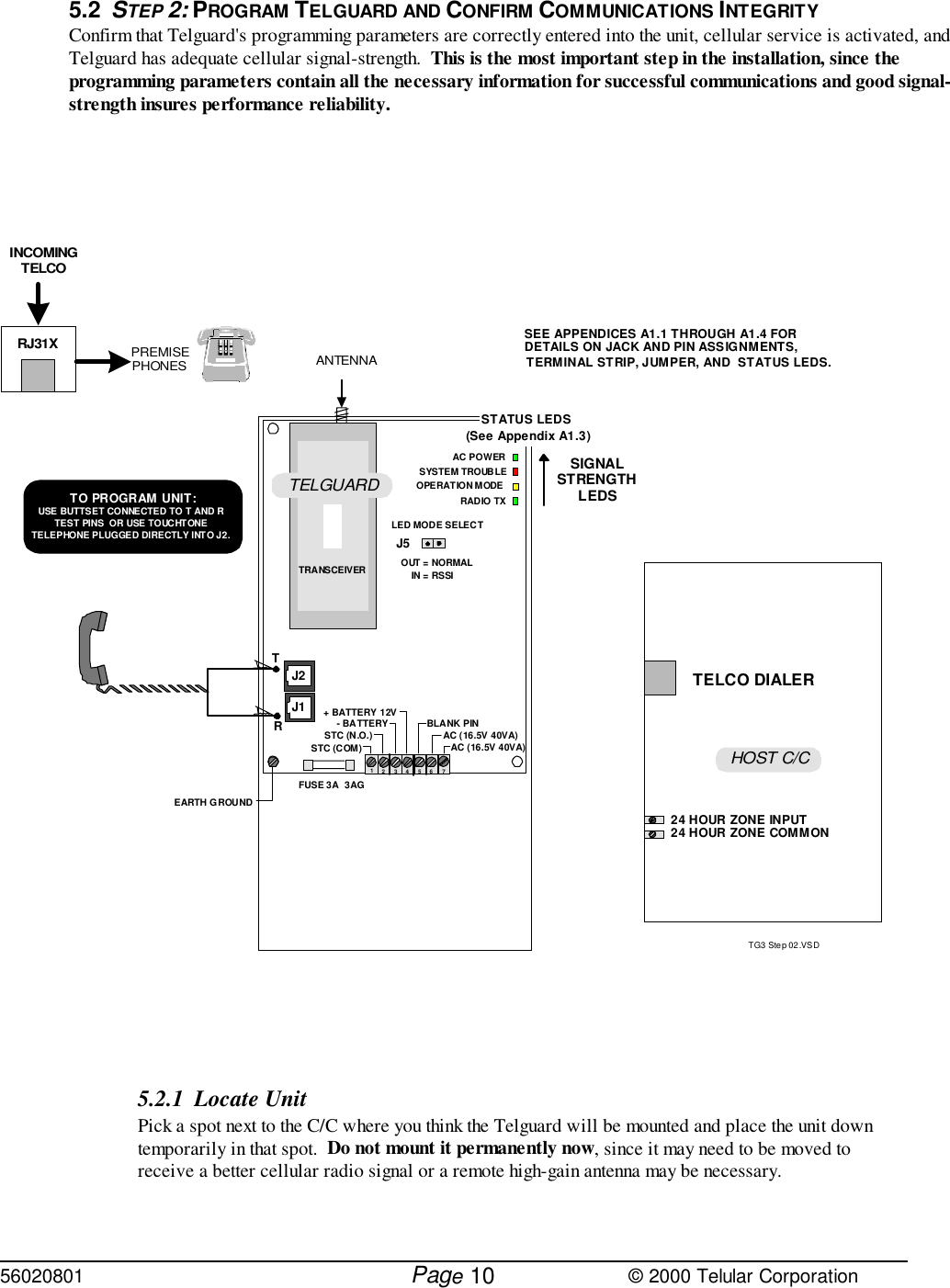
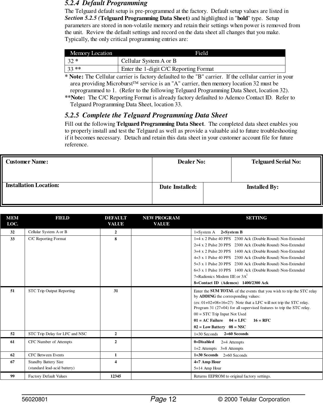
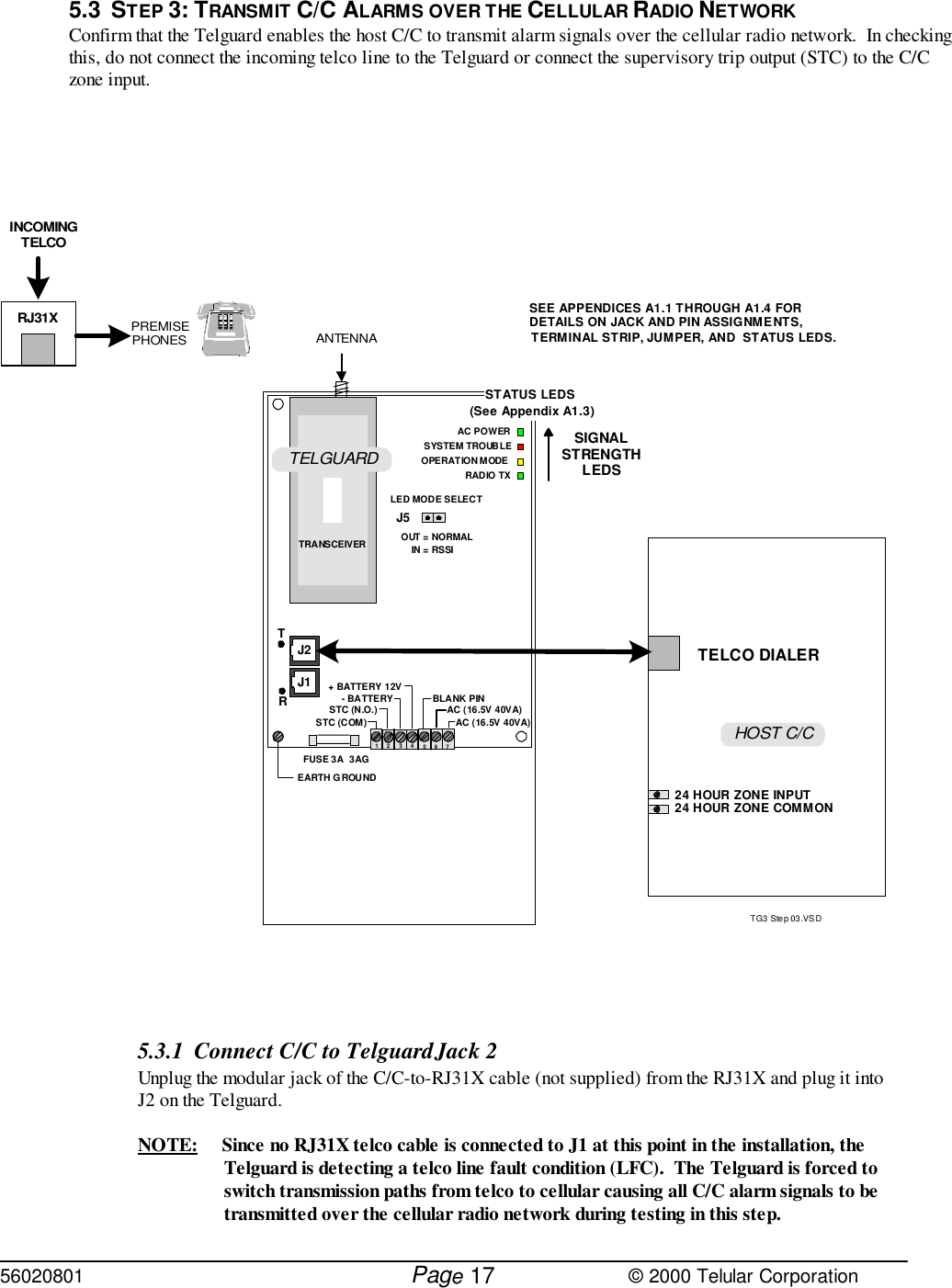
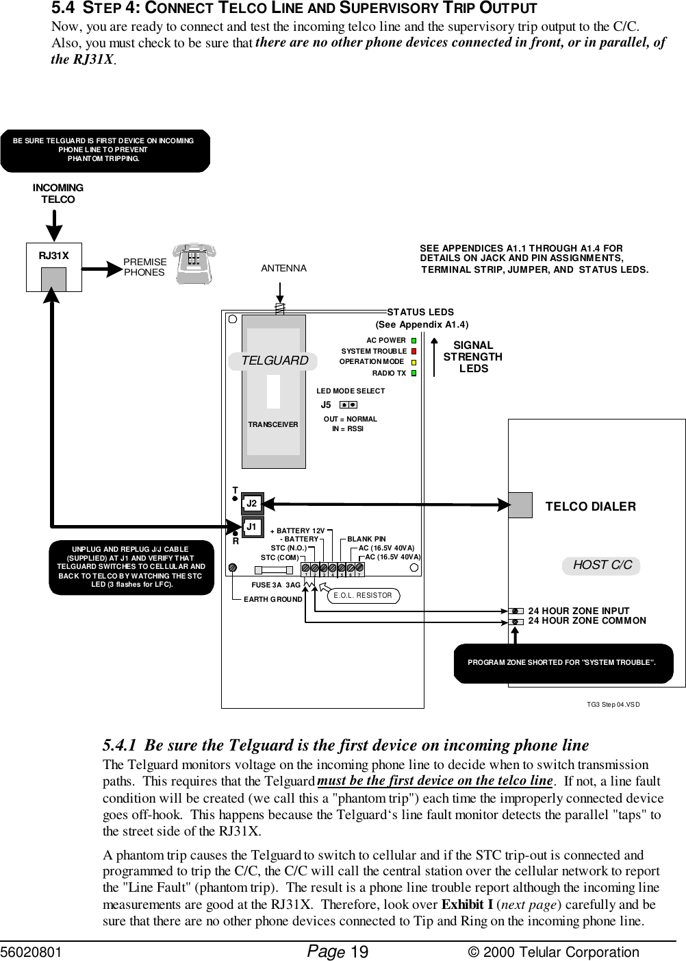
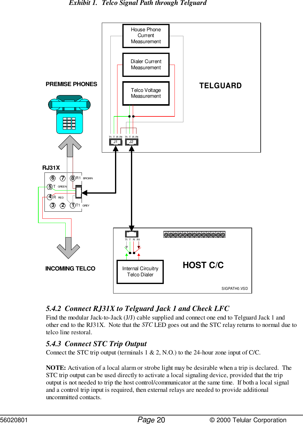
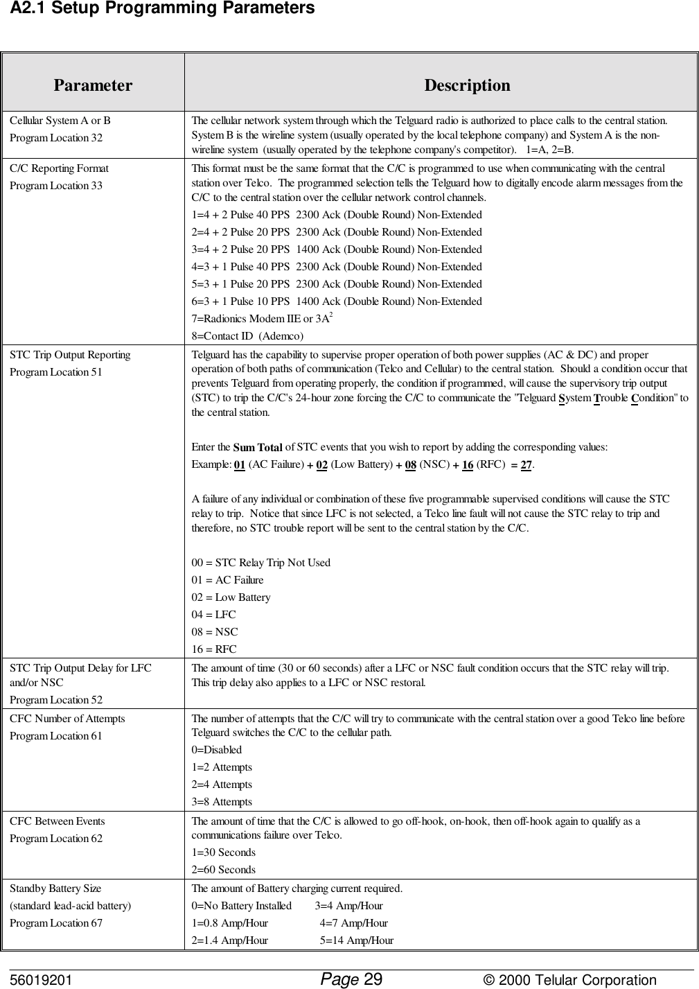
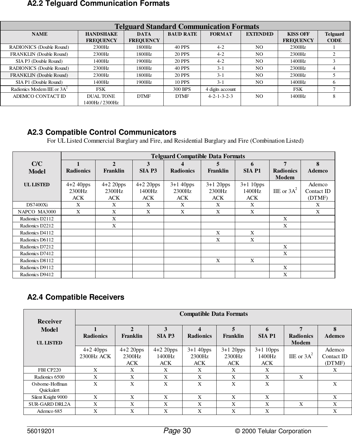
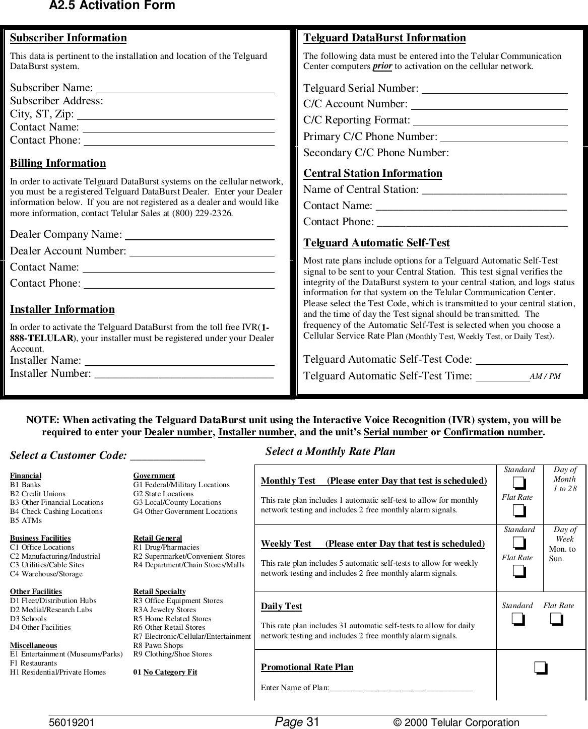
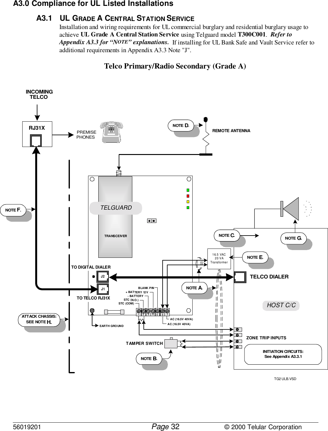
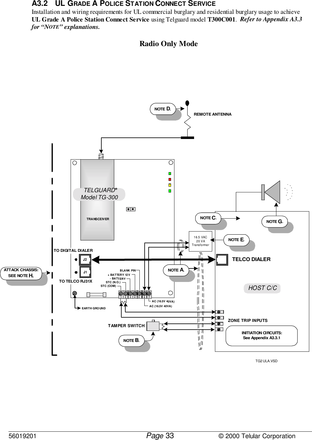
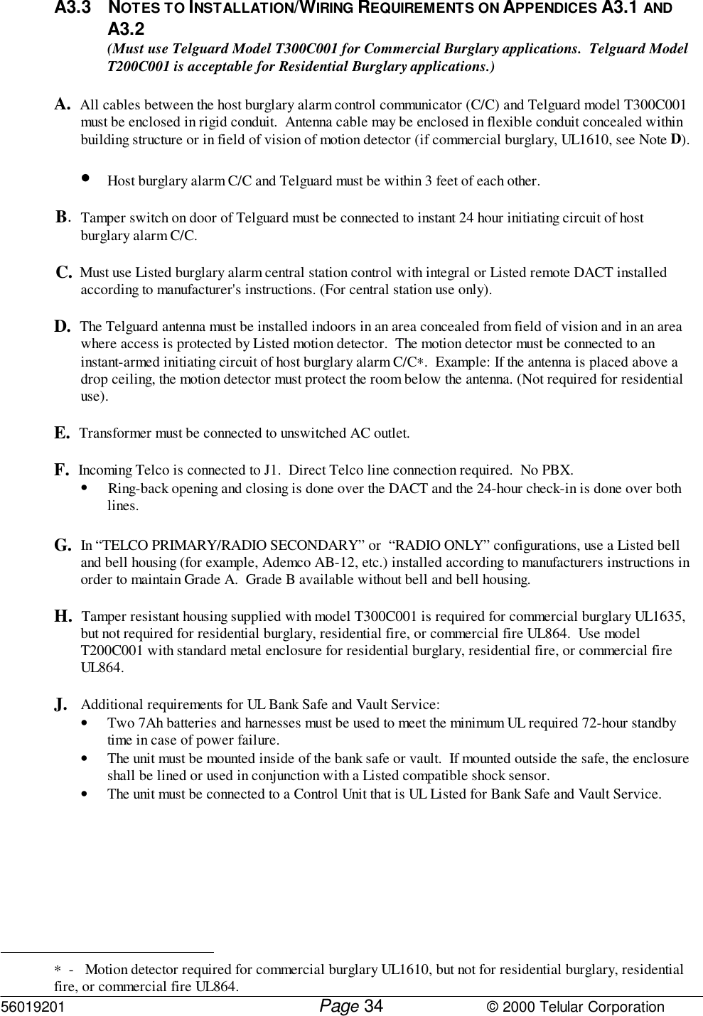
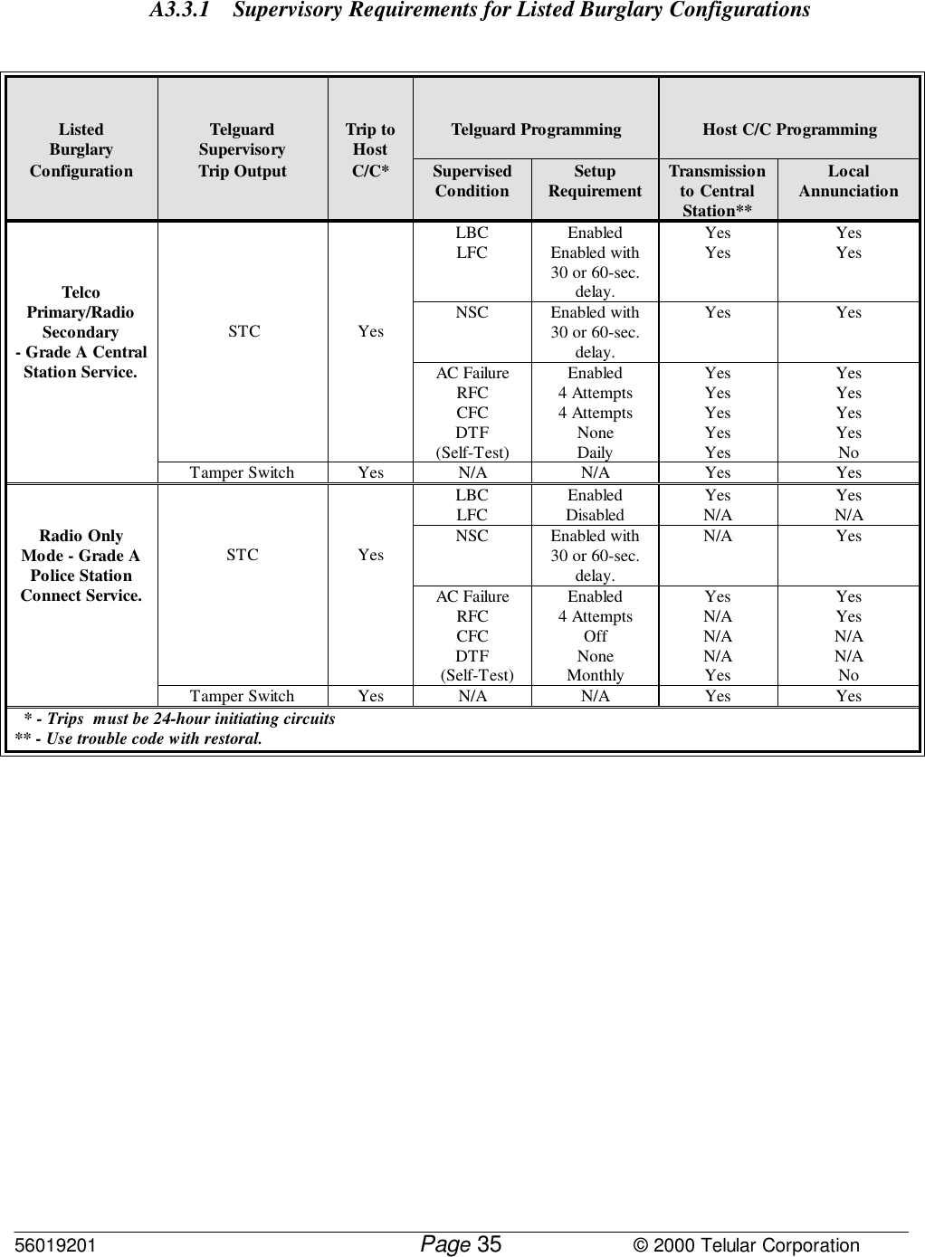
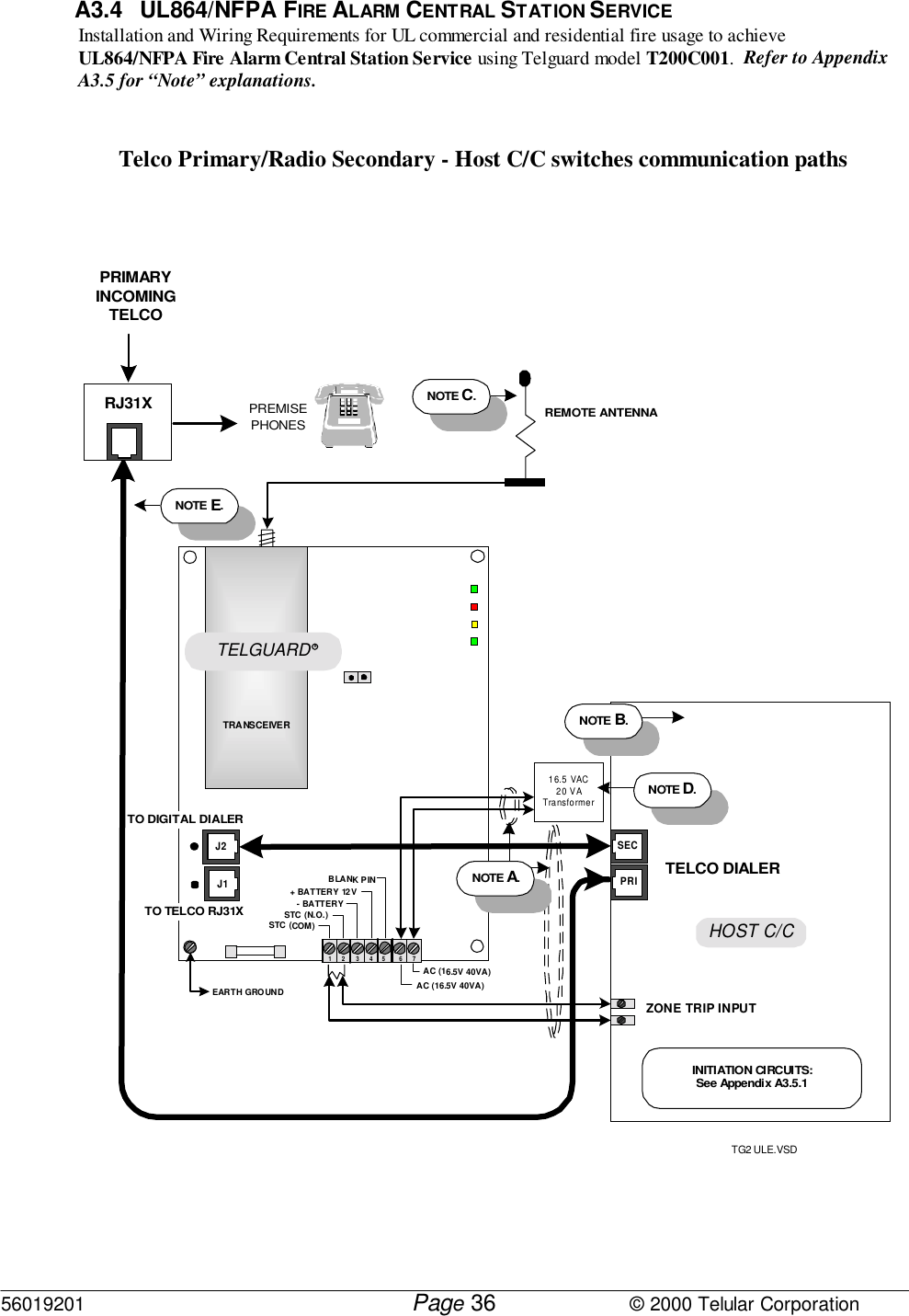
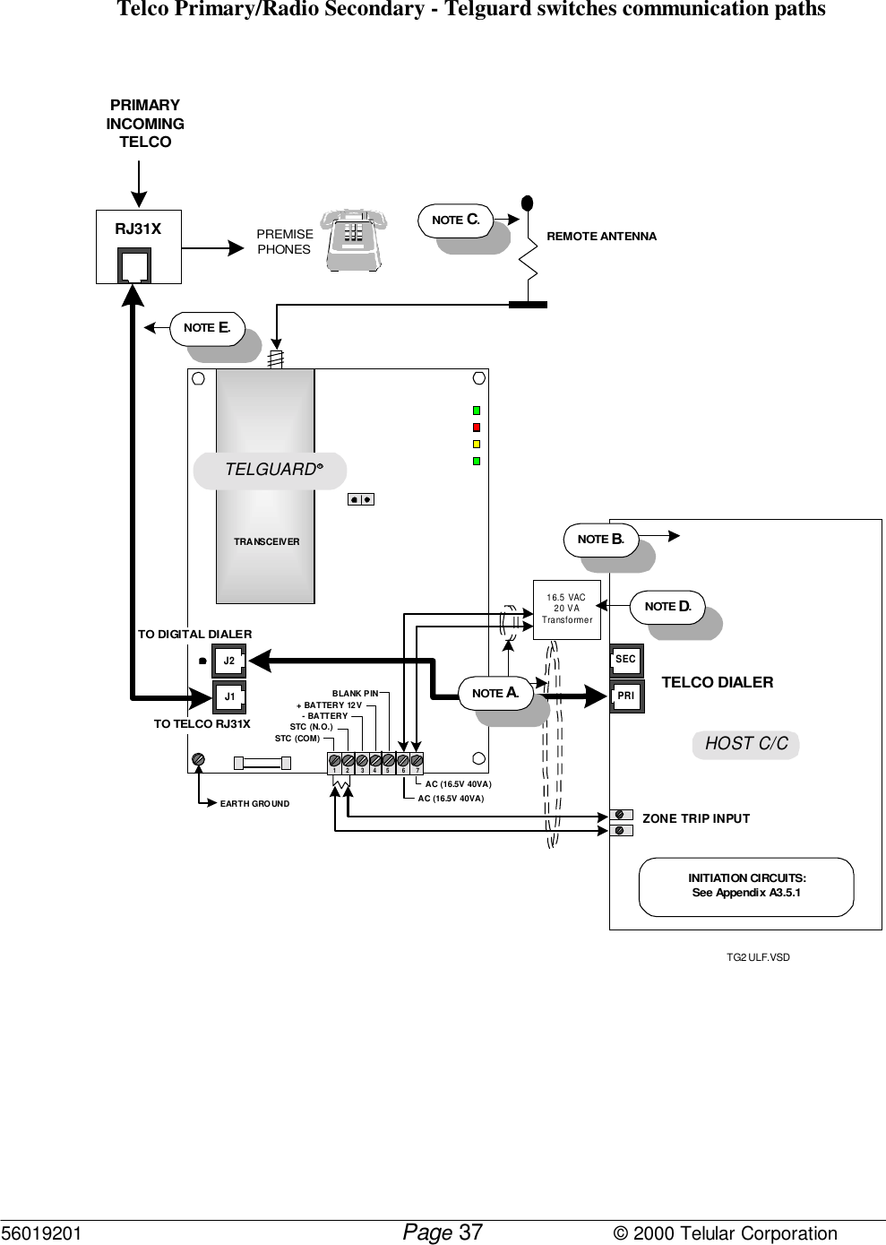
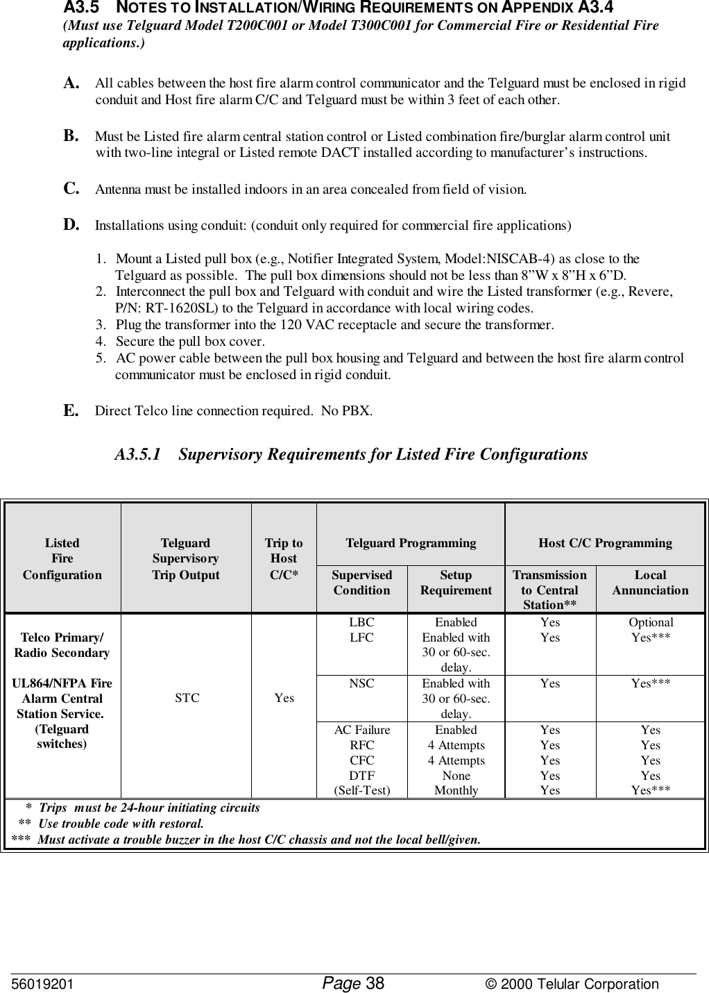
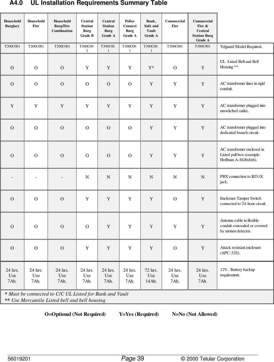
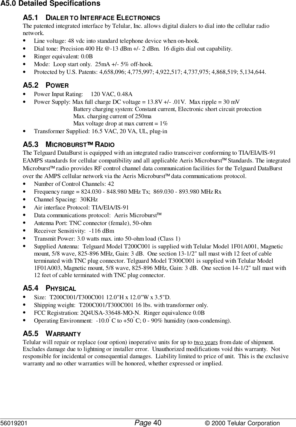
T200 T300 User Manual

56020801 © 2000 Telular CorporationTELGUARD®Cellular Alarm Transmission SystemUsing Microburst™ Control Channel TechnologyMODELS T200C001; T300C001ULRINSTALLATION AND OPERATING INSTRUCTIONSCOMPANY CONFIDENTIALFor use by TELGUARD® customers only.Distribution to others strictly prohibited.December 21, 2000TELGUARD® is a registered trademark of Telular Corporation. Products are protectedunder one or more of the following U.S. patents:             4,658,096         4,737,975         4,775,997         4,868,519         4,922,517       © 2000 Telular CorporationC O R P O R A T I O N®Corporate Headquarters647 North Lakeview ParkwayVernon Hills, Illinois 60061847-247-9400   Fax: 847-247-0021  T E L U L A R
56020801         Page                             © 2000 Telular CorporationiFOREWORDA word about the significance of our UL Listings: These UL Listings allow the Telguard models to meet certainrequirements of insurance companies, fire marshals, building inspectors and other regulatory authorities in burglaryand fire alarm service as follows:1. In Burglary Alarm Service: When used in conjunction with a Listed central station burglary alarm control unitwith integral or Listed DACT that is connected to a Listed Grade A bell and bell housing, the combinedcontrol/communicator and Telguard T300C001 is suitable for Grade A central station service.  This is one gradehigher than a Listed control/communicator can obtain on its own without some type of external line supervision,such as is involved in UL AA service.A UL Grade A Listing is available in installations where the host Listed burglary alarm control/communicatortransmits through the T300C001 solely on cellular ("Cellular only": No Telco; Cellular primary).  Also, wherethe control/communicator is switched to transmit over cellular when it can not reach the central station over telco("Cellular backup for Telco": Telco primary; Cellular secondary).The specific UL Listings for the T300C001 with respect to burglary alarm service are Residential Burglary,UL1023.  Central Station Burglar Alarm Systems, UL1610; Police Station Connected Alarm Systems, UL365; andDigital Alarm Communicators, UL1635.2. In Fire Alarm Service: When used in conjunction with a Listed central station fire alarm control unit with a two-telco line integral or Listed DACT, the combined control/communicator and Telguard T200C001 meet therequirements for commercial fire alarm usage under UL 864 and NFPA.  This enables the T200C001 to be thesecond "phone line" in commercial fire installations.In UL/NFPA Listed fire alarm installations, the Listed two-line fire alarm control communicator must always usetelco as the primary transmission path, switching to cellular only when and if it can not reach the central stationover telco.  Also, the T200C001 may be employed in residential fire, UL985 applications.Appendices A3.1 through A3.3.1 (burglary alarm service) and A3.4 through A3.5.1 (fire alarm service) show theinstallation configurations and the connections that must be made to meet various UL Listing requirements.
56020801         Page                             © 2000 Telular CorporationiiNOTICESABOUT THIS MANUALThis manual assumes that you have basic security system installation skills such as measuringvoltages, stripping wire, properly connecting wires together, connecting wires to terminals, andchecking phone lines.  It also assumes that you have a familiarity with the proper installation andprogramming tasks related to various Control/Communicator panels.The material and instructions covered in this manual have been carefully checked for accuracy andare presumed to be reliable.  However, Telular assumes no responsibility for inaccuracies andreserves the right to modify and revise this manual without notice.It is our goal at Telular to always supply accurate and reliable documentation.  If a discrepancy isfound in this documentation, please mail or fax a photocopy of the corrected material to:Telular Security ProductsTechnical Services Department420 Thornton Road, Suite 109Lithia Springs, GA 30122Fax: 678-945-1651© 2000 Telular Corporation.  Lithia Springs, GA U.S.A.  All rights reserved.FCC NoticesEXPOSURE TO RADIO FREQUENCY ENERGYIn 1991, the Institute of Electrical and Electronics Engineers (IEEE), and in 1992, the American NationalStandards Institute (ANSI), updated the 1982 ANSI Standard for safety levels with respect to human exposureto RF energy.  Over 120 scientists, engineers and physicians from universities, government health agenciesand industry, after reviewing the available body of research, developed this updated Standard.  In March,1993, the U.S. Federal Communications Commission (FCC) proposed the adoption of this updated Standard.The design of your Telular Telguard DataBurst complies with this updated Standard.  Of course, if youwant to limit RF exposure even further than the updated ANSI Standard, you may choose to install the unit ina manner that locates its antenna at an even greater distance from the general public than is recommended as aminimum by the standard.To insure compliance with the standard, when selecting a mounting location for your Telguard DataBurst donot mount it (or its associated antenna) in an area where the general public could reasonably be within 8inches (20 centimeters) of the antenna.EFFICIENT OPERATIONDo not operate your Telular product when holding the antenna.  Be sure to mount the unit such that its antenna is a minimum ofeight (8) inches (20 centimeters) is maintained from the general public.For the best service quality, keep the antenna free from obstructions and point the antenna straight up.ANTENNA CARE AND REPLACEMENTDo not use the unit with a damaged antenna.  If a damaged antenna comes into contact with the skin, a minorburn may result. Have your antenna replaced by a qualified technician immediately. Use only a manufacturer-approved antenna. Non-approved antennas, modifications, or attachments could impair service quality,damage the Telguard and violate FCC regulations.
56020801         Page                             © 2000 Telular CorporationiiiELECTRONIC DEVICESMost modern electronic equipment is shielded from RF energy.  However, RF energy from cellular devicesmay affect inadequately shielded electronic equipment.RF energy may affect improperly installed or inadequately shielded electronic equipment operating in homesand businesses.  Check with the manufacturer or its representative to determine if these systems areadequately shielded from external RF energy.Consult the manufacturer of any personal medical devices (such as pacemakers, hearing aids, etc.) todetermine if they are adequately shielded from external RF energy.BLASTING AREASTo avoid interfering with blasting operations, turn OFF your unit when in a “blasting area” or in areasposted:  “Turn off two-way radio.”  Construction crews often use remote control RF devices to set offexplosives.POTENTIALLY EXPLOSIVE ATMOSPHERESTurn OFF your unit when in any area with a potentially explosive atmosphere.  It is rare, but your TelguardDataBurst or its accessories could generate sparks.  Sparks in such areas could cause an explosion or fireresulting in bodily injury or even death.Areas with a potentially explosive atmosphere are often, but not always, clearly marked.  They includefueling areas such as gas stations; below deck on boats; fuel or chemical transfer or storage facilities; areaswhere the air contains chemicals or particles, such as grain, dust, or metal powders; and any other areawhere you would normally be advised to turn off your vehicle engine.Do not transport or store flammable gas, liquid or explosives in the area of your Telguard DataBurst oraccessories.Vehicles using liquefied petroleum gas (such as propane or butane) must comply with the National FireProtection Standard (FPA-58).  For a copy of this standard, contact the National Fire Protection Association,One Batterymarch Park, Quincy, MA 02269, Attn: Publications Sales Division.--------------------------------------------------------------------------------FCC PART 15 CLASS B COMPLIANCEThis equipment has been tested and found to comply with the limits for a Class B digital computing device, pursuant to Part15 of the FCC rules.  These limits are designed to provide reasonable protection against harmful interference in a residentialinstallation.  This equipment generates, uses and can radiate radio frequency energy and, if not installed and used inaccordance with the instructions, may cause harmful interference to radio communications.  However, there is no guaranteethat interference will not occur in a particular installation.  If this equipment does cause harmful interference to radio ortelevision reception, which can be determined by turning the equipment OFF and ON, the user is encouraged to try to correctthe interference by one or more of the following measures:• Reorient or relocate the radio/television antenna.• Increase the separation between the radio/television equipment and the Telguard terminal.• Connect the radio/television equipment to an outlet on a branch circuit different from that to which theTelguard terminal is connected.• Consult your Authorized Telular Dealer or an experienced radio/TV technician for additional suggestions.The user or installer may find the following booklet prepared by the Federal Communications Commissionhelpful, “Interference Handbook”.  The booklet is available from the U.S. Government Printing Office,Washington, DC  20402.The user shall not make any changes or modifications to the equipment unless authorized by the Installation and OperatingInstructions.  Unauthorized changes or modifications could void the user’s authority to operate the equipment.
56020801         Page                             © 2000 Telular CorporationivPART 68This equipment complies with Part 68 of the FCC Rules.  Located on the inside of the hinged door of Telguard modelsT200C001 and T300C001 is a label that contains, among other information, the FCC Registration Number and RingerEquivalence Number (REN) for this equipment.  If requested, this information must be provided to the Telephone Company.The Telguard Cellular Alarm Transmission System is registered for connection to the public telephonenetwork using an RJ38X or RJ31X jack. When selecting a mounting location, do not mount this unit in an areawhere the general public could reasonably be within 20cm (8 inches) of the antenna.The ringer equivalence number (REN) is used to determine the quantity of devices which may be connectedto the telephone line.  Excessive REN's on the telephone line may result in the devices not ringing in responseto an incoming call.  In most, but not all areas, the sum of the REN's should not exceed five (5.0).  To becertain of the number of devices that may be connected to the line, as determined by the total number ofREN's, contact the telephone company to determine the maximum of REN for the calling area.If the Telguard Cellular Alarm Transmission System caused harm to the telephone network, the TelephoneCompany will notify you in advance that temporary discontinuance of the service may be required.  But ifadvance notice is not practical, the Telephone Company will notify the customer as soon as possible.  Also,you will be advised of your rights to file a complaint with the FCC if you believe it is necessary.The telephone company may make changes in it's facilities, equipment, operation, or procedures that couldaffect the operation of the equipment.  If this happens, the Telephone Company will provide advance notice inorder for you to make the necessary modifications in order to maintain uninterrupted service.  If trouble isexperienced with the Telguard Cellular Alarm Transmission System please contact Telular TechnicalService in the U.S.A. for repair and (or) warranty information.Telular Security ProductsTECHNICAL SERVICES DEPARTMENT420 Thornton Road, Suite 109Lithia Springs, GA  30122Phone: (800) 229-2326If the trouble is causing harm to the telephone network, the Telephone Company may request that you remove the equipmentfrom the network until the problem is resolved.The customer (user) should not attempt any repair to the Telguard Cellular Alarm Transmission System. Repair of this equipment should be referred to only qualified technical personnel.Note that this equipment cannot be used on the public coin service provided by the Telephone Company. Connection to Party Line Service is subject to state tariffs.  (Contact the state public utility commission orcorporation commission for information).FUTURE TESTING AND LIMITATIONS ON USETelguard is part of an advanced design alarm-communication system.  It does not offer guaranteed protection againstburglary and fire.  Any alarm communication system is subject to compromise or failure.The Telguard will not work without power.  Devices powered by AC will not work if the AC power supply is offfor any reason, however briefly, and at the same time, the backup battery is missing, dead or not properly installed.The cellular radio network, needed to transmit alarm signals from a protected premises to a central monitoring station,may be inoperable or temporarily out of service.  Cellular radio networks are also subject to compromise bysophisticated methods of attack.
56020801         Page                             © 2000 Telular CorporationvThis equipment, like any other electrical device is subject to component failure.  Although this equipment is designedto be long lasting, the electrical components could fail at any time.Due to these limitations, we recommend that if the automatic self-test feature is not enabled, other arrangements bemade with the user to test the system at least once every three months.  Moreover, arrangements should also be madefor on site inspection/test by a licensed alarm installer at least once each year.
56020801         Page                             © 2000 Telular CorporationviTABLE OF CONTENTSFOREWORD..................................................................................................................................................................INOTICES...................................................................................................................................................................... IIABOUT THIS MANUAL ..................................................................................................................................................IIFCC NOTICES............................................................................................................................................................. IIEXPOSURE TO RADIO FREQUENCY ENERGY..................................................................................................................IIEFFICIENT OPERATION.................................................................................................................................................IIANTENNA CARE AND REPLACEMENT............................................................................................................................IIELECTRONIC DEVICES.................................................................................................................................................IIIBLASTING AREAS ........................................................................................................................................................IIIPOTENTIALLY EXPLOSIVE ATMOSPHERES....................................................................................................................IIIFCC PART 15 CLASS B COMPLIANCE.........................................................................................................................IIIPART 68 ......................................................................................................................................................................IVTECHNICAL SERVICES DEPARTMENT ...........................................................................................................................IVFUTURE TESTING AND LIMITATIONS ON USE ...............................................................................................IV1.0 GENERAL DESCRIPTION AND OPERATION...........................................................................................12.0 FEATURES........................................................................................................................................................12.1 OPERATING MODE............................................................................................................................................12.2 C/C COMPATIBLE COMMUNICATION FORMATS................................................................................................22.3 COMPLETE SUPERVISION OF COMMUNICATION PATHS.....................................................................................22.3.1 Line Fault Condition (LFC) ...................................................................................................................22.3.2 Telco Communications Failure Condition (CFC) .................................................................................22.3.3 No Service Condition (NSC)...................................................................................................................22.3.4 Radio Communications Failure Condition (RFC).................................................................................32.4 COMPLETE POWER SUPERVISION......................................................................................................................32.4.1 Low/Missing Battery Condition (LBC) ..................................................................................................32.4.2 AC Failure Condition (ACFC)................................................................................................................32.4.3 Watchdog Monitor/Reset (WR) ..............................................................................................................32.4.4 Catastrophic Failure (CF) .....................................................................................................................32.5 TELGUARD AUTOMATIC SELF-TEST REPORT .....................................................................................................42.5.1 Telguard Remote Query Capability.......................................................................................................42.6 TELGUARD TERMINAL STRIP CONNECTIONS.....................................................................................................42.6.1 Programmable Supervisory Trip Output (STC) Relay...........................................................................42.7 DIAGNOSTIC AND STATUS LEDS......................................................................................................................52.7.1 LED Signal Strength Indication.............................................................................................................52.8 TELGUARD SETUP PROGRAMMING PARAMETERS ..............................................................................................52.9 UL LISTINGS BY MODEL...................................................................................................................................62.9.1 Model T200C001....................................................................................................................................62.9.2 Model T300C001....................................................................................................................................63.0 REQUEST TELGUARD ACTIVATION FOR CELLULAR SERVICE FROM TELULAR .....................63.1 GETTING READY.........................................................................................................................................64.0 INSTALLATION SUMMARY.........................................................................................................................74.1 TRANSMIT C/C ALARMS OVER THE TELCO CONNECTION.................................................................................74.2 PROGRAM TELGUARD AND CONFIRM COMMUNICATIONS INTEGRITY ...............................................................74.3 TRANSMIT C/C ALARMS OVER THE CELLULAR RADIO NETWORK .....................................................................74.4 CONNECT TELCO LINE AND SUPERVISORY TRIP OUTPUT..................................................................................8
56020801         Page                             © 2000 Telular Corporationvii4.5 COMPLETE THE INSTALLATION .........................................................................................................................85.0 INSTALLATION STEPS .................................................................................................................................85.1 STEP 1: TRANSMIT C/C ALARMS OVER THE TELCO CONNECTION....................................................................95.2 STEP 2: PROGRAM TELGUARD AND CONFIRM COMMUNICATIONS INTEGRITY.................................................105.2.1 Locate Unit...........................................................................................................................................105.2.2 Connect Backup Battery and AC Power Transformer.........................................................................115.2.3 Decide on a STC Trip Output Strategy................................................................................................115.2.4 Default Programming...........................................................................................................................125.2.5 Complete the Telguard Programming Data Sheet...............................................................................125.2.7 Connect Antenna and Temporarily Place Unit....................................................................................135.2.8 Measure Received Signal Strength (RSSI) for Best Antenna Placement.............................................145.2.9 Request Telguard Activation "PING" from Telular's IVR...................................................................155.3 STEP 3: TRANSMIT C/C ALARMS OVER THE CELLULAR RADIO NETWORK.......................................................175.3.1 Connect C/C to Telguard Jack 2...........................................................................................................175.3.2 Verify Alarm Signal Transmissions over Cellular...............................................................................185.4 STEP 4: CONNECT TELCO LINE AND SUPERVISORY TRIP OUTPUT...................................................................195.4.1 Be sure the Telguard is the first device on incoming phone line ........................................................195.4.2 Connect RJ31X to Telguard Jack 1 and Check LFC............................................................................205.4.3 Connect STC Trip Output.....................................................................................................................205.4.4 Check Telguard Supervisory Trip to C/C ............................................................................................215.5 STEP 5: COMPLETE THE TELGUARD INSTALLATION .........................................................................................225.5.1 Check Settings ......................................................................................................................................225.5.2 Permanently Mount and Properly Ground the Telguard Chassis.......................................................22A1.0 APPENDICES .................................................................................................................................................22A1.1 WIRING DIAGRAM......................................................................................................................................23A1.2 JACK AND PIN ASSIGNMENTS ....................................................................................................................24A1.3 TERMINAL STRIP PIN ASSIGNMENTS ..........................................................................................................25A1.4 LED MODES AND FUNCTIONS ...................................................................................................................26A1.5 JUMPERS ....................................................................................................................................................27A2.0 OPERATIONAL QUICK REFERENCE TABLE........................................................................................28A2.1 SETUP PROGRAMMING PARAMETERS.................................................................................................29A2.2 TELGUARD COMMUNICATION FORMATS...........................................................................................30A2.3 COMPATIBLE CONTROL COMMUNICATORS.....................................................................................30A2.4 COMPATIBLE RECEIVERS........................................................................................................................30A2.5 ACTIVATION FORM....................................................................................................................................31A3.0 COMPLIANCE FOR UL LISTED INSTALLATIONS ...............................................................................32A3.1 UL GRADE A CENTRAL STATION SERVICE......................................................................................................32A3.2 UL GRADE A POLICE STATION CONNECT SERVICE ....................................................................................33A3.3 NOTES TO INSTALLATION/WIRING REQUIREMENTS ON APPENDICES A3.1 AND A3.2 .................................34A3.3.1 Supervisory Requirements for Listed Burglary Configurations..........................................................35A3.4 UL864/NFPA FIRE ALARM CENTRAL STATION SERVICE............................................................................36A3.5 NOTES TO INSTALLATION/WIRING REQUIREMENTS ON APPENDIX A3.4 .....................................................38A3.5.1 Supervisory Requirements for Listed Fire Configurations .................................................................38A4.0 UL INSTALLATION REQUIREMENTS SUMMARY TABLE .................................................................39A5.0 DETAILED SPECIFICATIONS....................................................................................................................40
56020801         Page                             © 2000 Telular CorporationviiiA5.1 DIALER TO INTERFACE ELECTRONICS .........................................................................................................40A5.2 POWER.......................................................................................................................................................40A5.3 MICROBURST RADIO ...............................................................................................................................40A5.4 PHYSICAL...................................................................................................................................................40A5.5 WARRANTY................................................................................................................................................40A6.0 PARTS LIST....................................................................................................................................................41INDEX..........................................................................................................................................................................42
56020801         Page                             © 2000 Telular Corporation11.0 GENERAL DESCRIPTION AND OPERATIONThe Telguard is a cellular radio alarm transmission device, which is used to provide a backup transmission path(cellular) for control communicators (C/Cs) in case the primary transmission path (telco) is not available.  Whentransmitting over cellular, Telguard obtains its data from the C/C by way of a telco interface.  The device transmits aLink Request to the Telular operated Communication Center and when a link acknowledgement is received, theTelguard handshakes with the C/C and causes the C/C to transmit the alarm data.  Telguard encodes the alarm data intodigital packet data protocol and transmits on one of twenty-one available control channels used by the local AMPScellular network provider.  The signal is routed from the network provider through the Aeris virtual network system tothe decoding (message) center.  The Communication Center performs like a central station receiver and issues thetransmission kiss-off when the last message in the transmission is received.  After decoding and reformatting, thealarm signal is routed over telco to the appropriate alarm company central station for action.Telguard is compatible with most control/communicators and no special equipment is needed at the premises or in thealarm monitoring station.  All Telguard programming is done with a standard touch-tone telephone or lineman’s buttsetand Telguard can be installed wherever cellular service is available.  Different dialing patterns between telco andcellular, cellular area code changes and PBX access numbers are not a problem for installers.  Fraud and cloningproblems are eliminated since all transmissions occur over the cellular control channels in packet-type data formatand never over any voice channels.In a typical alarm installation, Telguard is installed in the same area as the host alarm system.  The incoming telco lineis connected from the RJ31X to Telguard and then to the host control/communicator's digital dialer in the normalfashion.  A programmable supervisory trip (STC) output is available for connection to the host control/communicator'strip zone input terminals in order to provide a Telguard trouble signal to the C/C.  Additionally, automatic self-test andstatus-on-demand report signals are transmitted exclusively over the cellular network to the Communication Center. All models are capable of transmitting an automatic self-test signal to the central station on a daily, weekly, or monthlyschedule.  Telguard has its own internal power supply/battery charger.  All telco line and cellular monitoring,switching and supervisory functions are built in--no extra modules are required.All Telguard models come with a special Microburst™ compatible 3-watt cellular transceiver (without handset),antenna, interface with integrated control and power module, connecting cable, and plug-in transformer.  The installerto provide backup times that range from twenty-four to seventy-two hours must supply a rechargeable 12V battery,7.0AH or 14.0AH.  Model T200C001, UL Listed for residential and commercial fire, as well as residential burglary,comes in a standard metal enclosure (12in.x12in.x3½in.) with keylock and magnetic mount antenna with 12ft. of cable. Model T300C001, UL Listed for all residential burglary and fire, commercial burglary and fire, and bankapplications comes in an attack-resistant enclosure with keylock, tamper switch, and magnetic mount antenna. The Listed equipment at the Telular operated Communication Center (TCC) plays a key role in the operation of everyTelguard.  All Telguard units are required to use the Communication Center because of the C/C alarm signal formatencoding and decoding requirements used in packet-data transmissions over the cellular network control channels. The Communication Center also manages the real-time databases for cellular activation, airtime, billing, installationsite location, and a complete history of every Telguard's operating conditions.  These conditions include programmingsetup information, cellular alarm transmission information, supervisory trouble information, status-on-demandinformation, and automatic self-test information.  This information is made available to authorized personnel throughTelular's Interactive Voice Response System (IVR), Telular's computer access Communication Center Intranet System,or though Telular's Customer Service Center. 2.0 FEATURESThis section summarizes the key features of the Telguard.  Actual installation instructions begin in Section 5.0.2.1 OPERATING MODEThe Telguard is a cellular radio packet transmission device that is installed at the protected premises toprovide alarm transmission integrity for security systems.  It is used to provide a backup transmission path(cellular) for control communicators (C/Cs) in case the primary transmission path (telco) is not available.  Ifthe telco line is cut or the C/C is unable to communicate with the central station receiver due to busytelephone line circuits then Telguard transmits the alarm message over the cellular network.
56020801         Page                             © 2000 Telular Corporation22.2 C/C COMPATIBLE COMMUNICATION FORMATSThe Telguard reads the C/C’s alarm messages and converts the C/C’s digital data format into Microburstpacket data protocol for transmission over the cellular radio network.  In order for the C/C to be compatiblewith the Telguard, the C/C must be programmed to transmit alarm messages to the central station using one ofthe following non-extended formats:• 3+1 pulse; 10pps, Double Round, 1400Hz ack• 3+1 pulse; 20pps, Double Round, 2300Hz ack • 3+1 pulse; 40pps, Double Round, 2300Hz ack• 4+2 pulse; 20pps, Double Round, 1400Hz ack• 4+2 pulse; 20pps, Double Round, 2300Hz ack• 4+2 pulse; 40pps, Double Round, 2300Hz ack• Radionics Modem IIE or 3A2• Ademco Contact IDHexadecimal account numbers (001-FFF or 0001-FFFF) can be used with 3+1 or 4+2 formats, but ContactID and Radionics modem IIE or 3A2 requires a four digit account number using digits 0-9 (0001-9999).2.3 COMPLETE SUPERVISION OF COMMUNICATION PATHSThe Telguard continuously supervises both the primary (telco) and the secondary (cellular) communicationpaths.  If either path becomes inoperative, the Telguard generates a relay trip output that can be connected toa zone input of the host control communicator and/or used to activate remote sounding devices.  2.3.1 Line Fault Condition (LFC)The Telguard monitors voltage on the incoming telco line.  If an inoperative telco line is identified,a telco line fault condition (LFC) is declared and Telguard switches to the cellular path.  Once thetelco line restores to normal, Telguard checks the radio link and switches back to the telco path afterany communications on the radio link are completed.   LFC is programmable to trip the supervisory relay output (STC) after a 30 or 60 second delay. When the STC trips, the STC LED indicates 3 flashes at a time and the C/C zone trip message istransmitted to the alarm company central station indicating system trouble.  Upon telco restoral, theSTC relay and LFC LED are returned to normal and a STC restoral message is transmitted if theC/C is programmed to transmit restorals.2.3.1.1 PBX InstallationsPBX’s and other proprietary phone systems sometimes operate at lower voltages than thestandard telco line.  Telguard works equally well on PBX lines or telco lines. Note:  PBX connections are not allowed in any UL Listed installations.2.3.2 Telco Communications Failure Condition (CFC)Telco communications failure condition (CFC) is declared when the C/C fails to deliver the alarmmessage to the central station receiver after a selected number (1-5) of attempts over an operativetelco line.  Immediately upon CFC, Telguard switches to cellular mode and allows the C/C toattempt five transmissions over the cellular network.  If the call is not acknowledged after the fifthattempt, Telguard switches the C/C back to telco and “disarms” the CFC detection.  The CFCdetection is re-armed when the C/C has been on-hook continuously for ten-minutes.2.3.3 No Service Condition (NSC)Telguard declares a no service condition (NSC) when the measured “receive” cellular radio signalstrength at the protected premises drops to -114 dBm or less.  NSC is programmable to trip the supervisory relay output (STC) after a 30 or 60 second delay. When the STC trips, the STC LED indicates 4 flashes at a time and the C/C zone trip message istransmitted to the central station indicating system trouble.  Restoral of this condition occurs when ameasurable signal strength greater than –114 dBm is maintained for the trip period of 30 or 60seconds.
56020801         Page                             © 2000 Telular Corporation32.3.4 Radio Communications Failure Condition (RFC)Radio communications failure condition (RFC) is declared when Telguard is unable to transmitover the cellular network even with acceptable signal strength.  Two conditions can cause an RFCto occur, Link Request failure (RFC1) or Link Termination failure (RFC2).2.3.4.1 RFC1 (Link Request Failure)When a LFC or CFC has been declared and there is an alarm signal to communicate, theTelguard attempts to transmit its message via radio.  When the C/C goes off-hook, theTelguard transmits a Link Request to the TCC and waits for a Link Request ACK.  If theTelguard does not receive an ACK for the transmission before the C/C hangs up, it willretransmit the Link Request again when the C/C goes off-hook for a redial attempt.  If theTelguard does not receive an ACK after three attempts, then an RFC will be declaredwhich trips the STC relay, causes the STC LED to flash five times and switches theTelguard to Telco.  Restoral of RFC occurs when the communication cycle is completed.2.3.4.2 RFC2 (Link Termination Failure)After the Telguard receives a Link Request ACK from the TCC, the Telguardcommunicates with the C/C to acquire the alarm message and transmits the message viaradio.  If the Telguard does not receive a link termination ACK (where the TCCacknowledges receiving the transmission) within 150 seconds, it will retry sending theentire transmission.  Upon failing two attempts, the Telguard switches to Telco and allowsthe C/C to communicate directly with the Central Station.  An RFC is declared causing theSTC relay to trip and the STC LED to flash five times.  Restoral of RFC occurs when thecommunication cycle is completed. 2.4 COMPLETE POWER SUPERVISIONTelguard monitors its backup battery as well as its AC power source and reports low or missing powerconditions from either.  Telguard’s integrated control and power module, protected by a 3 amp 3AG fuse,incorporates battery charger circuitry that is jumper selectable for high or low battery capacities.  The highbattery capacity selection is used for 12V 7Ah, or 12V 21Ah batteries. 2.4.1 Low/Missing Battery Condition (LBC)The Telguard checks the backup battery voltage on initial power-up and every minute thereafter. Additionally, a battery voltage test is performed by the Telguard every 24-hours while operating onAC power in order to measure the loaded battery voltage.  Battery charging voltage is lowered to10.0 volts and the Telguard is forced to operate entirely from the battery supply.  If the batteryvoltage is less than 11.6 volts, a LBC is declared whereby the STC LED blinks twice (½ sec ON, ½sec OFF, ½ sec ON, ½ OFF every 5 seconds) and the STC relay trips.  When the battery voltageincreases to 12.1 volts, the STC LED and STC relay restore. 2.4.2 AC Failure Condition (ACFC)AC failure condition (ACFC) occurs when AC power is lost or less than 102 VAC for 6 continuoushours.  The AC Power LED goes out immediately, the STC LED blinks once and the STC trip outputis activated after 6 hours.  When AC power returns too normal (≥106 VAC for 60 seconds), the ACPower LED turns on immediately and the STC trip output restores after 60 seconds.2.4.3 Watchdog Monitor/Reset (WR)A watchdog monitor/reset (WR) circuit continuously monitors the Telguard’s internal operatingmicroprocessor functions.2.4.4 Catastrophic Failure (CF)Catastrophic Failure (CF) is any condition that causes the Telguard to stop functioning at all levels. Most commonly because of AC power failure followed by a complete discharge of the backupbattery.  The STC trip output is activated and visible indication is loss of all LED activity.  Totalloss of power to Telguard does not prevent transmission of alarm messages from the host C/C“through” the Telguard and out over an operative phone line in the normal fashion.
56020801         Page                             © 2000 Telular Corporation42.5 TELGUARD AUTOMATIC SELF-TEST REPORTThe Telguard automatic self-test signal is originated by the Communication Center on a daily, weekly, ormonthly schedule (note: UL Listed installations require a daily self-test).  When the time for an automaticself-test occurs, the Communication Center transmits a radio signal to the Telguard and the Telguard respondswith a self-test radio signal that is received by the Communication Center and processed on to the centralstation, just as normal alarm signals are processed.  The central station receives the automatic self-test reportin the same format that the C/C normally uses for communication over the telco line.  The central stationprovides the Telguard self-test code along with the time and frequency of transmission when the Telguard isinitially activated.  However, an automatic self-test report can be initiated later, after the Telguard isinstalled, as well as modifying the time or frequency of reporting.The Communication Center captures all current and historical data pertaining to the operation of the Telguardwhen it processes the automatic self-test signal on to the central station.  This data contains currentoperational status (C.O.S.) of the Telguard such as "All OK", "AC fail condition", "low/missing batterycondition", "line fault condition", or any combination of these as well as the current signal strength and modeof operation.  In addition, the data also contains historical data for supervisory events that occurred since thelast self-test signal was transmitted.  This data includes the number of occurrences of AC fail conditions, lowbattery conditions, line fault conditions, communications failure conditions and no cellular serviceconditions.  This self-test data is available for review at any time by authorized personnel such as installers,dealers, central station operators, or technical service personnel.  Methods used to review this data includeTelular's Interactive Voice Response System (IVR), Telular's computer access Communication CenterIntranet System, or simply calling Telular Customer Service who can review the data using the "Back Office"program.2.5.1 Telguard Remote Query CapabilityAlthough Telguard has the capability for a daily, weekly, or monthly automatic self-test, a separatefeature is provided for determining the current operational status of every Telguard.  This feature iscalled Remote Query and is used to provide real-time operational status for Telguard on-demand.  Itis useful in resolving STC events that are reported by the C/C to the central station.  Authorizedpersonnel can initiate the Remote Query at any time by accessing the IVR, Intranet, or callingCustomer Service.  The Remote Query causes Telguard to upload current operational status data andhistorical data, just as the automatic self-test described above, except that the query signal iscontrolled by the one who initiates it.  The query signal is held in the Telguard database at theCommunication Center for review and is not forwarded on to the central station.      2.6 TELGUARD TERMINAL STRIP CONNECTIONSThe conveniently located terminal strip provides wiring connections for the Telguard supervisory trip output(STC-pins 1&2, N.O.), battery leads for connecting to a 12 volt 7.0Ah, or 14.0AH rechargeable battery(BAT-pin 3 neg., pin 4 pos.), and AC power (16.5VAC 20VA, pins 6&7).   The removable terminal strip canaccommodate solid or stranded wire sizes from 14 gauge to 30 gauge.2.6.1 Programmable Supervisory Trip Output (STC) RelayThe Telguard has one supervisory relay trip output (STC), a single pole single throw (SPST, formC) with contacts rated at 1.0A 30VDC, and is energized normally open (N.O.) in a powered up statewhen no system troubles exist.  It enables a supervisory trouble code (zone shorted) to betransmitted to the central station when connected to a C/C’s 24-hour instant input zone.  The STCrelay is programmable, using a standard touch-tone telephone or buttset, to meet virtually anyinstallation requirement. The following supervisory features or combination of features are programmable to trip the STCrelay in order to meet a variety of installation requirements: • Always Off.• Trips on AC fail condition (ACFC)• Trips on low or missing battery condition (LBC).• Trips on line fault condition (LFC).• Trips on no service condition (NSC).• Trips on radio communication failure condition (RFC).
56020801         Page                             © 2000 Telular Corporation5NOTE: For UL installations, all the above features must be enabled.The following system trouble features are embedded in the Telguard for tripping the STC relay andcannot be changed:• Trips on catastrophic failure (CF) if all power is lost.• Trips on transmit-disable command from the Communication Center.  Thisradio command disables only the Telguard transmitter and would be used, forexample, to shut down the Telguard due to a runaway dialer.  The Telguardreceiver function stays active so that a transmit-enable command can bereceived by radio to put the Telguard back into normal service.2.7 DIAGNOSTIC AND STATUS LEDSFour LEDs are provided as a useful aid during installation and give installers an immediate visual indicationof system status.  These LEDs include an AC Power LED indicator that is green when AC power is normaland off when AC power is low or missing.  The red STC LED provides system trouble information forlow/missing AC power-ACFC (1 flash), low/missing battery-LBC (2 flashes), telco line fault-LFC (3flashes), no cellular service-NSC (4 flashes), radio communication failure-RFC (5 flashes) and loss of dial-tone voltage-DTF (6 flashes).  An Operating Mode LED indicates solid yellow for normal operating modeor slow flash for C/C off-hook when communicating over cellular.  A short (1 second) solid green Radio TXLED indicates it is in a Microburst communication cycle.  Separately, these LED’s can be converted into abar graph during installation to indicate radio signal strength by using a single jumper (J5) to select normalLED mode (off) or signal strength mode (on). 2.7.1 LED Signal Strength IndicationThe Telguard provides the installer with an easy to use LED radio signal strength indicator (RSSI)for positioning the unit or remote antenna to obtain the strongest RF signal possible.  A signalstrength reading can be obtained at any time there is power applied to the Telguard without affectingthe operation of the unit.  When the “RSSI” jumper J5 is “IN”, the Telguard displays the currentreceived signal strength within 5 seconds and should the jumper be inadvertently left “IN”; theTelguard will revert to normal display operation after 10 minutes.  The signal strength is read frombottom to top using the four sequential LEDs located on the top right side of the printed circuit boardwith the Radio TX LED = 1 and the AC POWER LED = 4.RSSI Value LED’s Lighted RF dBmNO SVC LED 1* = on,  LED 2-4 = off ≤ -116 dBm0 LED 1 = on,  LED 2-4 = off ≤ -111 dBm1 LED 1 = on,  LED 2 = slow flashLED 3-4 = off ≥ -110 dBm2 LED 1-2 = on,  LED 3-4 = off ≥ -100 dBm3 LED 1-2 = on,  LED 3 = slow flashLED 4 = off ≥ -90 dBm (Minimum signalstrength required)4 LED 1-3 = on,  LED 4 = off ≥ -80 dBm5 LED 1-3 = on ,  LED 4 = slow flash ≥ -70 dBm6 LED 1-4 = on ≥ -60 dBm*Note: LED 1 = Radio TX; LED 2 = Mode; LED 3 = STC; LED 4 = AC Power.2.8 TELGUARD SETUP PROGRAMMING PARAMETERS The Telguard will not operate until the unit is activated from the Communication Center.  There are noradio NAM programming requirements since the radios have been preprogrammed at the factory.  However,certain Telguard operating parameters may need to be changed from the factory default programming by theinstaller during installation in order to have the Communication Center process alarm signals to the centralstation.  These are setup parameters and are used to tell the Communication Center how to encode alarmmessages to the appropriate alarm monitoring station.  Included in the setup parameters are the C/C reportingformat and cellular operating system A or B.  Also included are the STC supervisory trip input settings, CFCsettings, NFC/LFC trip delay time, and standby battery size.  If operating parameters are not uploaded to theCommunication Center, a "missing parameters (MP) condition" exists and the Telguard will not operate. When an MP condition exists, the Telguard causes the STC LED to light and the STC (System Trouble) tripoutput to occur.
56020801         Page                             © 2000 Telular Corporation6If default programming is correct or operating parameters are re-programmed into the Telguard, the installercalls the Telular IVR and follows the activation procedure to request an activation "ping".  TheCommunication Center responds with a radio acknowledgement to the Telguard clearing the STC conditionand allowing the Telguard to operate over the cellular radio network.  The programmed parameters aretransmitted automatically to the TCC when the Telguard is activated.  The installer must perform any changesto the Telguard programming data since the Communication Center cannot download data to the unit.2.9 UL LISTINGS BY MODEL There is a Telguard model designed to meet UL requirements for virtually any residential and commercialburglary/fire installation.  All models contain the same circuitry and perform the same functions.  Thedifference between models is simply the type of enclosure and type of antenna that is shipped with the unit.2.9.1 Model T200C001Model T200C001 meets the requirements for Household Burglary, Household Fire, and CommercialFire installations.  T200C001 has a standard metal enclosure, keylock, and magnetic mount antennawith 12ft.cable.  T200C001 is UL Listed for the following:♦ UL Household Burglary♦ UL Household Fire♦ UL Household Burg/Fire Combination♦ UL Commercial Fire2.9.2 Model T300C001Model T300C001 meets the requirements for all Household Burglary, Commercial Burglary,Household Fire, and Commercial Fire installations.  T300C001 has an attack-resistant enclosure,keylock, tamper switch, and a magnetic mount antenna with 12ft.cable.  Model T300C001 is ULListed for the following and UL Listed for Grade A Burglary Certificate installations:♦ UL Household Burglary♦ UL Household Fire♦ UL Household Burg/Fire Combination♦ UL Central Station Burglary! Grade A! Grade B♦ UL Police Connect Burglary! Grade A♦ UL Commercial Fire♦ UL Commercial Fire and Central Station Burglary Grade A♦ UL Bank, Safe and Vault! Grade A3.0 Request Telguard Activation for Cellular Service from TelularThere are two ways that you may activate cellular service for a Telguard.  Both methods require the activationinformation to be completed and approved prior to installing the Telguard.  The Telguard can only be activated whenall the necessary accounting information has been entered into the customer database located at the TelularCommunication Center.  The database includes information about the customer account, unit location, and centralstation information.1. FAX Cellular Service Activation Form: Complete the Cellular Service Activation Form that is shipped witheach Telguard and fax it to Telular Customer Service, 678-945-1651.  Within 24-hours, you will be notifiedof service activation. 2. Computer access via Telular's Intranet: Dealers may access their Telguard customer database viaTelular's Intranet.  The pertinent customer account information and serial number can be completed andsubmitted on-line.  After an approval acknowledgement is issued, usually within 10-minutes, the Telguard isready to install. 3.1 GETTING READYBefore attempting to connect Telguard to the host C/C, please note the following:
56020801         Page                             © 2000 Telular Corporation71.   Be sure your unit has cellular service activated.  (See Section 3.0)2.   Be sure you have all the proper parts before you go to the job site.  The following items are shipped witheach Telguard unit:" Basic Telguard unit (Model T200C001 in standard metal enclosure, or Model T300C001 in attackenclosure with tamper switch)." 16.5 VAC, 20 VA UL Listed plug-in transformer (Revere, P/N: RT-1620SL). Note: The 20 VA transformer is required for proper operation since the Telguard iscapable of transmitting at 3 watts of output power.  Do not use the C/C powertransformer to provide AC power to the Telguard." Antenna: Magnetic-mount 3dB-gain antenna with 12ft. cable for T200C001 or 5dB-gain antenna forT300C001." 3-foot modular plug-to-plug cord for connecting Telguard to RJ31X jack." Telguard Installation and Operating Instructions Manual, P/N: 56020801" Account Activation and Programming form documenting the unit's electronic serial number, cellulartelephone number, etc.NOTE:  Backup batteries are not supplied with any models.  You must source backup batteriesseparately.  The T200C001 and T300C001 have flying leads with terminals for convenient plug-inconnections to the larger capacity batteries. All Telguard Models Approx. StandbyTime 12V. BatteryCapacity Manufacturer/model24-Hours 7.0 Ah Technacell EP 1270T200C001/T300C001 72-Hours 14.0 Ah (2 ea. 7.0Ah) Technacell EP 12703.   You must also have certain installation test tools. • A standard telephone or lineman's buttset is required at the job site for use in programming the unit. • Optimal signal strength is determined by placing the unit where the most LEDs (up to four) arelighted when using Telguard's on-board Signal Strength Indicator feature so that the unit can beeasily placed during installation where signal strength is greatest.NOTE: Your unit may be subject to airtime charges for unintended use.  Telular offers several cellularservice rate plans.  Check the Activation and Programming form that was shipped with your unitor call us to determine what rate plan each unit is operating under.4.0 INSTALLATION SUMMARYThere are five steps in installing Telguard properly.  IF YOU DO NOT PROCEED IN THE ORDER ANDMANNER PRESCRIBED, YOU MAY NOT COMPLETE THE INSTALLATION IN THE TIMEALLOCATED.  These five steps are summarized below and then explained in detail in the remainder of this manual.4.1 TRANSMIT C/C ALARMS OVER THE TELCO CONNECTIONFirst, make sure you can transmit alarm signals from the C/C host to the central monitoring station over thetelco line without any connection to Telguard. 4.2 PROGRAM TELGUARD AND CONFIRM COMMUNICATIONS INTEGRITYNext, you will be confirming that Telguard's programming parameters are correctly entered into the unit and cellularservice is activated.  This is the most important step in the installation, since the programming parameterscontain all the necessary information for successful communications.  Also, you will confirm that Telguard hasadequate cellular signal strength.4.3 TRANSMIT C/C ALARMS OVER THE CELLULAR RADIO NETWORKNext, you will be connecting the C/C's digital dialer output to Telguard and verifying that alarm signals canbe reliably sent through Telguard over cellular to the central station digital receiver.  The incoming Telcoline is not connected to Telguard during this step.
56020801         Page                             © 2000 Telular Corporation84.4 CONNECT TELCO LINE AND SUPERVISORY TRIP OUTPUTOnce alarms are being successfully transmitted over cellular by the C/C, you will be ready to connectTelguard to the incoming phone line at the RJ31X and check that it properly switches to and from cellularupon telco restoral and telco line fault.  Telguard's supervisory trip output (normally open) is connected to a24-hour zone of the C/C and then tested.When backing up the host C/C's phone line, Telguard must be the first device on the incoming phoneline in order to prevent Telguard from going into Telco Line Fault Condition when a phone device infront of it goes off-hook.  This is the step where this is checked.4.5 COMPLETE THE INSTALLATIONYour last step will be to check the jumper setting of J5 (LED mode, out = normal), attach earth ground, andpermanently mount the unit. *  *  *  *With this overview of the installation in mind, you should now proceed with the actual installation, followingthe steps described in the remainder of this manual.  Experienced installers following these steps can usuallyinstall Telguard in new installations with good signal strength in a maximum of 30 minutes and inretrofit/existing installations in a maximum of one hour.  However, you must first get the host C/C workingcorrectly when transmitting over the incoming telco line.If you come to a road block at any step during the installation of Telguard, call Telular Technical SupportDepartment immediately before going on to the next step, so that we can help you complete each step in theproper order.5.0 INSTALLATION STEPSThis five-step installation approach (5.1 through 5.5) provides the alarm installer with the easiest and fastest methodof properly installing Telguard.  Please follow the instructions carefully and if you should need assistance or have anyquestions, call forTECHNICAL SUPPORT:1-800-229-2326 / 678-945-7770 FAX:  678-945-1651TELULAR IVR (Interactive Voice Response):   678-945-0228  (Local-Area: Atlanta, Ga.)1-888-TELULAR (Toll-Free: 1-888-835-8527)TELULAR INTRANET (Computer Dial-up Connection): 678-945-1993
56020801         Page                             © 2000 Telular Corporation95.1 STEP 1: TRANSMIT C/C ALARMS OVER THE TELCO CONNECTIONBe sure the C/C is powered up and programmed so that it will transmit a simple alarm signal over the telcoline through the RJ31X to the central station when not connected to the Telguard.  In checking this, do notconnect the host C/C or incoming telco line to the Telguard.TG2 Step 1.VSDHOST C/C24 HOUR ZONE COMMON24 HOUR ZONE INPUTTELCO DIALERRJ31XPREMISEPHONESINCOMINGTELCOMAKE SURE HOST C/C IS PROGRAMMEDAND WORKING THROUGH RJ31XBEFORE  INSTALLING TELGUARD.
56020801         Page                             © 2000 Telular Corporation105.2 STEP 2: PROGRAM TELGUARD AND CONFIRM COMMUNICATIONS INTEGRITYConfirm that Telguard's programming parameters are correctly entered into the unit, cellular service is activated, andTelguard has adequate cellular signal-strength.  This is the most important step in the installation, since theprogramming parameters contain all the necessary information for successful communications and good signal-strength insures performance reliability. 5.2.1 Locate UnitPick a spot next to the C/C where you think the Telguard will be mounted and place the unit downtemporarily in that spot.  Do not mount it permanently now, since it may need to be moved toreceive a better cellular radio signal or a remote high-gain antenna may be necessary.TG3 Step 02.VSDHOST C/C24 HOUR ZONE COMMON24 HOUR ZONE INPUTTELCO DIALERDETAILS ON JACK AND PIN ASSIGNMENTS,TERMINAL STRIP, JUMPER, AND  STATUS LEDS.SEE APPENDICES A1.1 THROUGH A1.4 FORJ2FUSE 3A  3AGSIGNALSTRENGTHLEDSSTATUS LEDS(See Appendix A1.3)TR123456STC (COM)STC (N.O.)+ BATTERY 12V- BATTERY7AC (16.5V 40VA)AC (16.5V 40VA)BLANK PINJ1TO PROGRAM UNIT:USE BUTTSET CONNECTED TO T AND RTEST PINS  OR USE TOUCHTONETELEPHONE PLUGGED DIRECTLY INTO J2.EARTH G ROUNDRAC POWERSYSTEM TROUBLERADIO TXOPERATION MODEANTENNATRANSCEIVERRJ31XPREMISEPHONESINCOMINGTELCOTELGUARDLED MODE SELECTJ5IN = RSSIOUT = NORMAL
56020801         Page                             © 2000 Telular Corporation115.2.2 Connect Backup Battery and AC Power TransformerTo apply power on models T200C001 or T300C001 attach battery leads to terminals 3 (-) and 4 (+)noting polarity and program Telguard memory location 67 (see section 5.2.5) for proper batterycapacity.  Connect the Telguard AC power transformer to terminals 6 and 7 marked "AC 16.5V 20VA" usingstranded copper insulated wire following wire gauge and length recommendations below:Recommended Wire Size Length Not to Exceed18 ga 20 ft16 ga 40 ft14 ga 60 ft5.2.3 Decide on a STC Trip Output StrategyThe Telguard provides the host C/C with one supervisory trip output for reporting a Telguardsystem trouble code to the central station.  The supervisory trip output (terminals 1 & 2, N.O.) isprogrammable via a touch-tone telephone or buttset to suit various installation requirements.  Theprogramming options for this supervisory trip output can be any combination of the following(except Always off):a. Always Off: Disables all relay supervisory functions with relay in N.C. condition.b. ACFC: Trips 6-hours after loss of AC power.  Restores 60 seconds after AC power is restored.c. LBC: Trips within 60 seconds on low battery condition.  Restores when battery voltage ≥ 12.1vdc.d. LFC: Trips 30/60-sec. on Telco line fault condition.  Restores 30/60 seconds after Telco linerestores.e. NSC: Trips 30/60-sec. on no service condition due to loss of RF signal strength.  Restores30/60 seconds after RF signal strength is available.f. RFC: Trips on radio failure to communicate with the Telular Communication Center due toeither of the following:1. Failing to receive a Link Request acknowledgement from the Communication Centerafter 3 Link Request transmissions.  A Link Request transmission is generated eachtime the C/C goes off-hook to dial when the Telguard is in radio mode.  The LinkRequest acknowledgment from the Communication Center allows the Telguard tobegin accepting and transmitting alarm data from the C/C.2. Failing to receive a Link Termination acknowledgement from the CommunicationCenter after 2 complete transmission retries.  A Link Termination acknowledgementis generated by the Communication Center only when all messages in an alarmtransmission have been received successfully.Refer to Appendix A3.3.1 for UL supervisory requirements for Listed burglary configurations andAppendix A3.5.1 for Listed fire configurations.
56020801         Page                             © 2000 Telular Corporation125.2.4 Default ProgrammingThe Telguard default setup is pre-programmed at the factory.  Default setup values are listed inSection 5.2.5 (Telguard Programming Data Sheet) and highlighted in "bold" type.  Setupparameters are stored in non-volatile memory and retain their settings when power is removed fromthe unit.  Review the default settings and record on the data sheet all changes that you make. Typically, the only critical programming entries are:Memory Location Field32 *Cellular System A or B33 ** Enter the 1-digit C/C Reporting Format* Note: The Cellular carrier is factory defaulted to the "B" carrier.  If the cellular carrier in yourarea providing Microburst™ service is an "A" carrier, then memory location 32 must bereprogrammed to 1.  (Refer to the following Telguard Programming Data Sheet, location 32).**Note:  The C/C Reporting Format is already factory defaulted to Ademco Contact ID.  Refer toTelguard Programming Data Sheet, location 33. 5.2.5 Complete the Telguard Programming Data Sheet Fill out the following Telguard Programming Data Sheet.  The completed data sheet enables youto properly install and test the Telguard as well as provide a valuable aid to future troubleshootingif it becomes necessary.  Detach and retain this data sheet in your customer account file for futurereference.Customer Name: Dealer No: Telguard Serial No:Installation Location:  Date Installed:  Installed By:MEMLOC. FIELD DEFAULTVALUE NEW PROGRAMVALUE SETTING32 Cellular System A or B 21=System A     2=System B33 C/C Reporting Format 81=4 x 2 Pulse 40 PPS   2300 Ack (Double Round) Non-Extended2=4 x 2 Pulse 20 PPS   2300 Ack (Double Round) Non-Extended3=4 x 2 Pulse 20 PPS   1400 Ack (Double Round) Non-Extended4=3 x 1 Pulse 40 PPS   2300 Ack (Double Round) Non-Extended5=3 x 1 Pulse 20 PPS   2300 Ack (Double Round) Non-Extended6=3 x 1 Pulse 10 PPS   1400 Ack (Double Round) Non-Extended7=Radionics Modem IIE or 3A28=Contact ID  (Ademco)   1400/2300 Ack51 STC Trip Output Reporting 31 Enter the SUM TOTAL of the events that you wish to trip the STC relayby ADDING the corresponding values:(ex: 01+02+08+16=27)  Note that a LFC will not trip the STC relay. Program 31 (27+04) for all supervised features to trip the STC relay.00 = STC Trip Input Not Used01 = AC Failure     04 = LFC      16 = RFC02 = Low Battery   08 = NSC52 STC Trip Delay for LFC and NSC 21=30 Seconds     2=60 Seconds61 CFC Number of Attempts 2 0=Disabled      2=4 Attempts1=2 Attempts   3=8 Attempts62 CFC Between Events 1 1=30 Seconds    2=60 Seconds67 Standby Battery Size(standard lead-acid battery)44=7 Amp Hour5=14 Amp Hour99 Factory Default Values 12345 Returns EEPROM to original factory settings.
56020801         Page                             © 2000 Telular Corporation135.2.6 Setup & Programming When the Telguard is received from the factory and is powered up for the first time, it isimmediately ready for activation after a 10-second delay, provided the default settings are what youwant.  The STC LED turns on steady and the STC relay is tripped.  If changes to the default valuesare required, then the Telguard is re-programmed with a plain old telephone set (POTS) connectedto J2 where the C/C is usually connected.  A standard lineman's buttset (set to TALK and TONEmodes) can also be used when connected to the tip (T) and ring (R) test pins on the printed circuitboard (PCB) adjacent to JI and J2.  Put jumper J5 "IN" and power up the Telguard.  The TelguardProgramming Data Sheet explains the programming options and memory locations. NOTE:  The telephone line input to J1 must be disconnected prior to programming and theantenna must be connected.  The Telguard will transmit the programming setup data to thecommunication center automatically when you activate the Telguard using the Telular IVR.5.2.6.1 Command Key Sequences For POTS Re-ProgrammingKey Sequence Descriptionmemorylocation, value Selects memory-location and stores data.*Exits and stores programming.The syntax for programming a specific memory location is as follows:Memorylocation (2 digits), value.For example, to re-program the Telguard to transmit over the "A" carrier, the installer would powerdown the Telguard; put jumper J5 "IN", connect the buttset to T and R test pins, and then power upthe unit.  After approximately 10 seconds, four tones will be sounded on the buttset indicating entryinto programming mode.  After entering 32, two tones will be sounded on the buttset indicating entryinto a valid memory location (in this case, location 32).  After the digit 1 is entered, four tones willbe sounded on the buttset indicating a valid entry has been selected.  If an invalid memory locationor data value is entered, a long low tone will be sounded before the normal tones.  To re-enter acorrect value, the memory location must be entered again and then a correct value for thatmemory location. NOTE: To reset Telguard programming to factory default values, program memory location99 with 12345 and the Telguard will reload factory default data to the EEPROM (This takesabout 10 seconds!).  The Telguard will now be ready to activate with factory default values orto re-program again, just as it was received from the factory.To exit programming mode, press *.  Two tones will be sounded on the buttset.  Remove jumper J5and disconnect the buttset.  The Telguard does not need to power down and back up again unlessyou changed from B to A carrier or from A to B carrier.  The red STC LED will remain on and theSTC relay will remain tripped.  Call the Telular IVR (888-TELULAR) and follow the “newactivation or re-programming” menu.  When the Telguard transmits the setup programminginformation to the Communication Center successfully, the red STC LED will begin flashing a Telcoline fault trouble (LFC=3 flashes), the yellow Mode LED will turn on, and the AC power LED willturn on if AC is connected.  This indicates the unit is in normal operating mode and is ready totransmit alarm signals. 5.2.7 Connect Antenna and Temporarily Place Unit The Telguard is supplied with an antenna that is connected directly to the unit.  If a stronger radiosignal is required, the unit with antenna connected must be moved to a better signal location.  The
56020801         Page                             © 2000 Telular Corporation14characteristics of the Telguard antenna can be altered depending upon the wall material andmaterials contained within the wall chosen for mounting.  These effects may not be clearly identifiedby RSSI monitoring alone.  The wall materials may have a more profound affect on the antennastransmit band performance.  Best antenna performance will be obtained when the Telguard ismounted on a dry wall (plaster) with the antenna centered between wall studs and there are no metalobjects (such as water pipes or electrical conduit or air ducts) contained within the wall directlybehind, above or below the Telguard's antenna.  Never mount the Telguard on a metal surface or ona wall that contains metal material.When selecting a mounting location, do not mount this unit in an area where the general public couldreasonably be within 20cm (8 inches) of the antenna.Note 1: Optimum RF performance can usually be found at the highest point within a building with the fewestnumber of walls between the Telguard’s antenna and the outside of the premises.Note 2: To avoid interference with other electronic devices operating in the area, avoid mounting the Telguard’santenna near other electronic devices.  Highest radiated RF energy is in the direct horizontal line of the antenna. Therefore vertical separation (moving electronic devices or the Telguard’s antenna either higher or lower on thewall) provided higher levels of RF isolation from the Telguard.Note 3: The Telguard DataBurst unit is designed for indoor installations ONLY.  Mounting the Telguard outdoorswill cause system failure and may constitute a shock hazard to humans.  However, a Telguard remote antenna canand should, whenever possible, be mounted outdoors for least RF interference.These considerations should be coupled with the best RSSI indication obtainable (see section5.2.8).  Care should be taken to insure that a large metal object such as a refrigerator or a metalcabinet is not located on the opposite side of the wall under consideration.  Additionally, when thesystem is armed, care should be taken that metal overhead doors or security gates are not moved intoa position that might cause a reduction of radio signal. If moving the Telguard to a different location is not practical, then you may need a longer cable onthe remote antenna in order to receive adequate radio signal strength.  Pick a high, visually securespot, using the guidelines below. 5.2.7.1 Tips for Improved Radio Signal Reception• The higher the antenna the better.  So, start in the drop ceiling above the unit andproceed up from there, to the roof if necessary. • Remember, the antenna should be as inconspicuous as possible for greatest visualsecurity.  If on the roof, plan to place the antenna in PVC tubing or in a custom woodenstructure.• Try to keep the antenna away from sources of RF interference, including pumps,compressors, ovens, etc., or where metal objects can shield it or otherwise block thecellular radio RF signal.• Place the antenna perpendicular to the ground, either right side up or upside down.  Donot mount the antenna horizontally.5.2.8 Measure Received Signal Strength (RSSI) for Best Antenna PlacementMeasure the received signal strength by putting jumper J5 "IN".  This switches the LEDs to signalstrength mode.  Now, slowly move the unit or remote antenna to achieve maximum signal strength. Pick the place where the most LEDs (up to four) are lighted.  The LEDs are located on the top-rightside of the PCB and are read from bottom to top with the Radio TX LED = 1 and the AC PowerLED = 4.  At least two lighted LEDs with the third LED flashing are necessary to assurecontinuous, trouble free operation.  Move antenna slowly and check often.  Only a few inches canmake a great difference in signal strength.LED Function Table – View RSSI ModeRSSI Value LED’s Lighted RF dBmNO SVC LED 1* = on, 2-4 = off ≤ -116 dBm
56020801         Page                             © 2000 Telular Corporation150 LED 1 = on, 2-4 = off ≤ -111 dBm1 LED 1 = on, 2 = slow flashLED 3-4 = off ≥ -110 dBm2 LED 1-2 = on, LED 3-4 = off ≥ -100 dBm3 LED 1-2 =ON, 3 =SLOW FLASHLED 4 = off ≥≥≥≥ -90 dBm (Minimum signalstrength required)4 LED 1-3 = on, LED 4 = off ≥ -80 dBm5 LED 1-3 = on , 4 = slow flash ≥ -70 dBm6 LED 1-4 = on ≥ -60 dBm*Note: LED 1 = Radio TX; LED 2 = Mode; LED 3 = STC; LED 4 = AC Power.NOTE: If you can not obtain a signal strength reading of TWO LEDS ON SOLID AND THETHIRD LED ON SLOW FLASH, you will probably need to move the unit and/or remoteantenna higher, or switch to a special antenna, as described below.5.2.8.1 Antenna OptionsAntenna problems are unlikely unless the premises are located in a fringe networkcoverage area, in a building below ground level, or in a metal structure.  However, hereare your options:Magnetic Mount 3-dB gain Antenna with 12ft. Cable:  The 3dB magnetic mount antennacomes with 12 feet of cable (Telular model no: 1F01A001 ).Magnetic Mount 5-dB gain Antenna with 12ft. Cable: The 5dB magnetic mount antennacomes with 12 feet of cable (Telular model no: 1F01A003 ).NOTE: After determining the best signal strength location for the antenna, set theRSSI jumper J5 "OUT" to return to normal operating mode.  If the “RSSI”jumper is inadvertently left "IN", Telguard will automatically cancel theRSSI LED mode after 10 minutes and return the LEDs to normal operation. During the 10-minute interval, Telguard will still operate normally.5.2.9 Request Telguard Activation "PING" from Telular's IVRWhen you are ready to install and test the Telguard, call Telular's IVR (Interactive Voice Response)number, 1-888-TELULAR (1-888-835-8527).  The automated system will ask you for the followinginformation: (All information must be supplied correctly) Reminder!!! The Activation form must be faxed to the Telular Communication Center (fax:678-945-1651) and entered into the database before this step can occur.a) Dealer number? b) Tech number? c) Telguard Serial Number?  Or, Confirmation Number if the Serial Number has not beenpreviously submitted on the Activation Form.d) New Telguard programming/reprogramming or Requesting Status Report?  (Select theprogramming menu.)After you have programmed the Telguard, entered the correct Dealer, Tech, Telguard Serial number(or Confirmation Number), and selected "yes" for new install or reprogram on the menu, a radio"activation ping" will be generated from the Communication Center to the Telguard.  This activatesthe Telguard and allows the Telguard to communicate over the cellular network.  A successful"ping" causes the red STC LED to turn off.  Additionally, if the Telguard is programmed to monitorLFC, then the STC LED will begin to flash 3 times indicating a telco line fault condition since thereis no telco line connected to J1 at this time.  Also, the yellow Mode LED will turn on and if ACpower is connected, the green AC power LED will turn on. Now, combined with other data previously submitted with the activation information such asautomatic self-test data, the communication center is able to process alarm signals from the host C/Cto the alarm monitoring station.
56020801         Page                             © 2000 Telular Corporation16Note to Installers: The Telguard must be powered-up with antenna connected in order to receivethe "activation ping".  Also, the Telular IVR system will allow you to enter a TEST menu to accessthe Telguard's operational history (e.g., number of occurrences of ACFC, LBC, LFC, and NSC sincethe last self-test transmission to the communication center).  Only the Dealer number, Tech number,and serial number are required to enter the TEST menu if the unit has already been activated.  Thisfeature is extremely helpful when troubleshooting intermittent problems such as NSC or LFC.MOVE ON Once you have completed the Telguard Programming Data Sheet, confirmed Telguard programming, receivedthe "activation ping" from the Communication Center and have good signal-strength, move on to Step 3.
56020801         Page                             © 2000 Telular Corporation175.3 STEP 3: TRANSMIT C/C ALARMS OVER THE CELLULAR RADIO NETWORKConfirm that the Telguard enables the host C/C to transmit alarm signals over the cellular radio network.  In checkingthis, do not connect the incoming telco line to the Telguard or connect the supervisory trip output (STC) to the C/Czone input.5.3.1 Connect C/C to Telguard    Jack 2 Unplug the modular jack of the C/C-to-RJ31X cable (not supplied) from the RJ31X and plug it intoJ2 on the Telguard. NOTE: Since no RJ31X telco cable is connected to J1 at this point in the installation, theTelguard is detecting a telco line fault condition (LFC).  The Telguard is forced toswitch transmission paths from telco to cellular causing all C/C alarm signals to betransmitted over the cellular radio network during testing in this step. TG3 Step 03.VSDHOST C/C24 HOUR ZONE COMMON24 HOUR ZONE INPUTTELCO DIALERDETAILS ON JACK AND PIN ASSIGNMENTS,TERMINAL STRIP, JUMPER, AND  STATUS LEDS.SEE APPENDICES A1.1 THROUGH A1.4 FORJ2FUSE 3A  3AGTR12 34 56STC (COM)STC (N.O.)+ BATTERY 12V- BATTERY7AC (16.5V 40VA)AC (16.5V 40VA)BLANK PINJ1EARTH G ROUNDRANTENNATRANSCEIVERRJ31XPREMISEPHONESINCOMINGTELCOTELGUARDLED MODE SELECTJ5IN = RSSIOUT = NORMALSIGNALSTRENGTHLEDSAC POWERSYSTEM TROUBLERADIO TXOPERATION MODESTATUS LEDS(See Appendix A1.3)
56020801         Page                             © 2000 Telular Corporation185.3.2 Verify Alarm Signal Transmissions over Cellular  Trip several alarms on the C/C and verify that the central station received them by calling thecentral station operator.  Use a lineman's buttset in MONITOR MODE and connected to Telguard's"T" and "R" test pins to "listen" to communications between the C/C and Telguard.  The Radio TXLED flashes quickly when the Telguard microprocessor is communicating with the radio andprovides a long flash (approximately 1 second) when the radio is in communication with the cellularnetwork.If you are having problems getting reliable alarm signal transmissions, additional adjustments maybe necessary.♦ Recheck signal strength.  You need TWO LEDS ON SOLID AND THE THIRD LEDFLASHING for adequate signal strength.  Also, check antenna connector and make sure it isseated correctly.♦ Try resetting the Telguard by powering the unit down then back up again. ♦ Call Telular Technical Service, 800-229-2326, and request the Communication Center operatorto check the Telguard programming configuration for proper operation on "A" carrier or "B"carrier and proper communications format.  The Telguard MUST be programmed to use theSAME FORMAT that the C/C is using (e.g. 3+1, 4+2, etc.,) to report alarm signals.MOVE ON Once you have determined that the C/C can reliably transmit alarm signals over the cellular network, proceedto Step 4.
56020801         Page                             © 2000 Telular Corporation195.4 STEP 4: CONNECT TELCO LINE AND SUPERVISORY TRIP OUTPUTNow, you are ready to connect and test the incoming telco line and the supervisory trip output to the C/C. Also, you must check to be sure that there are no other phone devices connected in front, or in parallel, ofthe RJ31X. 5.4.1 Be sure the Telguard is the first device on incoming phone lineThe Telguard monitors voltage on the incoming phone line to decide when to switch transmissionpaths.  This requires that the Telguard must be the first device on the telco line.  If not, a line faultcondition will be created (we call this a "phantom trip") each time the improperly connected devicegoes off-hook.  This happens because the Telguard‘s line fault monitor detects the parallel "taps" tothe street side of the RJ31X. A phantom trip causes the Telguard to switch to cellular and if the STC trip-out is connected andprogrammed to trip the C/C, the C/C will call the central station over the cellular network to reportthe "Line Fault" (phantom trip).  The result is a phone line trouble report although the incoming linemeasurements are good at the RJ31X.  Therefore, look over Exhibit I (next page) carefully and besure that there are no other phone devices connected to Tip and Ring on the incoming phone line.TG3 Step 04.VSDHOST C/C24 HOUR ZONE COMMON24 HOUR ZONE INPUTTELCO DIALERDETAILS ON JACK AND PIN ASSIGNME NTS,TERMINAL STRIP, JUMPER, AND  STATUS LEDS.SEE APPENDICES A1.1 THROUGH A1.4 FORJ2FUSE 3A  3AGTR123456STC (COM)STC (N.O.)+ BATTERY 12V- BATTERY7AC (16.5V 40VA)AC (16.5V 40VA)BLANK PINJ1EARTH G ROUNDUNPLUG AND REPLUG J/J CABLE(SUPPLIED) AT J1 AND VERIFY THATTELGUARD SWITCHES TO CELLULAR ANDBACK TO T ELCO BY WATCHING THE STCLED (3 flashes for LFC).PROGRAM ZONE SHORTED FOR "SYSTEM TROUBLE".E.O.L. RESISTORRANTENNATRANSCEIVERRJ31XPREMISEPHONESINCOMINGTELCOTELGUARDLED MODE SELECTJ5IN = RSSIOUT = NORMALSIGNALSTRENGTHLEDSAC POWERSYSTEM TROUBLERADIO TXOPERATION MODESTATUS LEDS(See Appendix A1.4) BE SURE TELGUARD IS FIRST DEVICE ON INCOMINGPHONE LINE TO PREVENTPHANTOM TRIPPING.
56020801         Page                             © 2000 Telular Corporation20Exhibit 1. Telco Signal Path through TelguardRJ31XHOST C/CPREMISE PHONESINCOMING TELCOSIGPATH0.VSD234567T  GREENR  RE DR1  BROWNT1  GREY8T1   T   R  R1J1T1   T   R  R1J2Telco VoltageMeasurementHouse PhoneCurrentMeasurementDialer CurrentMeasurement1Internal CircuitryTelco DialerT1  T    R   R1TELGUARD5.4.2 Connect RJ31X to Telguard Jack 1 and Check LFC Find the modular Jack-to-Jack (J/J) cable supplied and connect one end to Telguard Jack 1 andother end to the RJ31X.  Note that the STC LED goes out and the STC relay returns to normal due totelco line restoral. 5.4.3 Connect STC Trip Output Connect the STC trip output (terminals 1 & 2, N.O.) to the 24-hour zone input of C/C.NOTE: Activation of a local alarm or strobe light may be desirable when a trip is declared.  TheSTC trip output can be used directly to activate a local signaling device, provided that the tripoutput is not needed to trip the host control/communicator at the same time.  If both a local signaland a control trip input is required, then external relays are needed to provide additionaluncommitted contacts.
56020801         Page                             © 2000 Telular Corporation215.4.4 Check Telguard Supervisory Trip to C/C After you have connected the STC trip output, check to be sure that it operates correctly.5.4.4.1 Reprogram C/C to Send Proper CodeReprogram C/C to send proper alarm code when tripped by the Telguard’s supervisoryoutput.  Program zone restoral as desired.5.4.4.2 Check Proper Operation of Telguard Supervisory OutputCheck for proper operation of each programmed supervisory output by causing it to trip theC/C and be sure the proper LED illuminates and that the proper trouble code is reported tothe central station.  Skip the testing of any supervisory functions that have not been enabled. Note that the yellow mode LED starts to flash when the C/C goes off-hook to report thealarm signal over cellular.  The yellow mode LED stays on solid when the C/C goes off-hook to report the alarm signal over Telco.• Low Battery Condition (LBC): Disconnect the battery and during the next 60 secondscheck to see that the STC LED flashes 2 times indicating that the battery is missing. Check to see that the C/C transmits the STC trouble code (over Telco) to the centralstation.  Reconnect the battery and check during the next 60 seconds to see that theSTC LED goes off, indicating the missing battery condition has been restored.  If theC/C is programmed for transmitting restorals, another transmission will be sent (overTelco) to the central station.• Line Fault Condition (LFC): Disconnect J/J cable at RJ31X.  Check to see that theSTC LED flashes 3 times in 30/60 seconds and the C/C transmits the STC troublecode (over radio) to the central station indicating the incoming telco line isdisconnected.  Reconnect J/J cable and check to see that the STC LED goes off in30/60-seconds indicating telco line restoral.  If the C/C is programmed for transmittingrestorals, another transmission will be sent to the central station (over Telco) after the30/60-second delay.• No Service Condition (NSC): Disconnect the antenna from the Telguard.  Check tosee that the STC LED flashes 4 times in 30/60 seconds and the C/C transmits the STCtrouble code over the telco line indicating loss of RF signal strength.  Reconnect theantenna and check to see that the STC LED goes off in 30/60-seconds indicating RFsignal strength restoral.  If the C/C is programmed for transmitting restorals, anothertransmission will be sent to the central station (over Telco) after the 30/60-seconddelay.Note: The Received Signal Strength (RSSI) must be less than -114 dBm in order tocause a NSC condition.  If the Telguard is located in a high signal strength area (closeto a cellular tower), it is possible for the signal strength to be greater than -114 dBmeven with the antenna disconnected.• AC Fail Condition (ACFC): Disconnect the 20VA AC transformer and check to seethat the AC POWER LED goes out and the STC LED flashes once indicating that ACpower is missing.  Reconnect the AC transformer and check to see that the ACPOWER LED goes on and the STC LED goes off indicating that AC power has beenrestored.  No transmissions will be sent to the central station.  The AC power must beoff, continuously, for 6-hours before the STC relay causes the C/C to send a troublecode.  If the AC power is restored for 60 seconds or more, then the 6-hour timerrestarts.MOVE ON When you are sure that the Telguard is monitoring the telco path and cellular path correctly and the C/C is correctlyreporting the STC supervisory trip output, move on to Step 5.
56020801         Page                             © 2000 Telular Corporation225.5 STEP 5: COMPLETE THE TELGUARD INSTALLATIONLast step is to handle loose ends.5.5.1 Check SettingsCheck the jumper setting of J5 (LED mode, out = normal).  5.5.2 Permanently Mount and Properly Ground the Telguard Chassis Attach earth ground to the green grounding screw located on lower left-hand corner of printedcircuit board assembly and permanently mount the Telguard chassis.A1.0 APPENDICESA1.1 WIRING DIAGRAM......................................................................................................................................23A1.2 JACK AND PIN ASSIGNMENTS ....................................................................................................................24A1.3 TERMINAL STRIP PIN ASSIGNMENTS ..........................................................................................................25A1.4 LED MODES AND FUNCTIONS ...................................................................................................................26A1.5 JUMPERS ....................................................................................................................................................27A2.0 OPERATIONAL QUICK REFERENCE TABLE........................................................................................28A2.1 SETUP PROGRAMMING PARAMETERS.................................................................................................29A2.2 TELGUARD COMMUNICATION FORMATS...........................................................................................30A2.3 COMPATIBLE CONTROL COMMUNICATORS.....................................................................................30A2.4 COMPATIBLE RECEIVERS........................................................................................................................30A2.5 ACTIVATION FORM....................................................................................................................................31A3.0 COMPLIANCE FOR UL LISTED INSTALLATIONS ...............................................................................32A3.1 UL GRADE A CENTRAL STATION SERVICE......................................................................................................32A3.2 UL GRADE A POLICE STATION CONNECT SERVICE ....................................................................................33A3.3 NOTES TO INSTALLATION/WIRING REQUIREMENTS ON APPENDICES A3.1 AND A3.2 .................................34A3.3.1 Supervisory Requirements for Listed Burglary Configurations..........................................................35A3.4 UL864/NFPA FIRE ALARM CENTRAL STATION SERVICE............................................................................36A3.5 NOTES TO INSTALLATION/WIRING REQUIREMENTS ON APPENDIX A3.4 .....................................................38A3.5.1 Supervisory Requirements for Listed Fire Configurations .................................................................38A4.0 UL INSTALLATION REQUIREMENTS SUMMARY TABLE .................................................................39A5.0 DETAILED SPECIFICATIONS....................................................................................................................40A5.1 DIALER TO INTERFACE ELECTRONICS .........................................................................................................40A5.2 POWER.......................................................................................................................................................40A5.3 RADIO........................................................................................................................................................40A5.4 PHYSICAL...................................................................................................................................................40A5.5 WARRANTY................................................................................................................................................40A6.0 PARTS LIST....................................................................................................................................................41INDEX..........................................................................................................................................................................42
56019201         Page                             © 2000 Telular Corporation23A1.1 WIRING DIAGRAMHOST C/C24 HOUR ZONE COMMON24 HOUR ZONE INPUTTELCO DIALERJ2FUSE 3A  3AGTR12 34 56STC (COM)STC (N.O.)+ BATTERY 12V*- BATTERY7AC (16.5V 40VA)*AC (16.5V 40VA)BLANK PINJ1EARTH GROUNDE.O.L. RESISTORTG3 WIRING.VSDWARNING:  HIGH VOLTAGE PRESENT ONPHONE LINES.  DISCONNECTPRIOR TO SERVICING.*  INDICATES SUPERVISED CIRCUIT.THIS DEVICE COMPLIES WITH FCC RULES PART68 AND 15.FCC REGISTRATION NO: XXXXX-XXXX-XRINGER EQUIVALENCE:  0.0BTELGUARD® is a registered trademark of TelularCorporation.  Products are protected under one or more ofthe following U.S. patents:   4,658,096     4,737,9754,775,997      4,868,519     4,922,517.© 2000 Telular Corporation.CAUTION:  INCORRECT CONNECTIONS MAYRESULT IN DAMAGE TO UNIT.DO NOTCONNE CT  TO ASWITCHED ACREC EP T ACL E.*Note: AC terminals 6 and 7 are power limited.SIGNALSTRENGTHLEDSAC POWERSYSTEM TROUBLERADIO TXOPERATION MODESTATUS LEDS(See Appendix A1.4)ANTENNATRANSCEIVERRJ31XPREMISEPHONESINCOMINGTELCOTELGUARDLED MODE SELECTJ5IN = RSSIOUT = NORMALSTC Relay Maximum Contact Rating: 1A-30VDC
56019201         Page                             © 2000 Telular Corporation24A1.2 JACK AND PIN ASSIGNMENTSJackDesignation Connects To Pin Assignment Function Status LEDReferenceJ1Telco RJ31X.Incoming TelcoRJ31X Jack. 1  Gray R14  Red R(Ring)5  Green T(Tip)8  Brown T1Connects telco line toTelguard and providesoutput for premises phoneconnection at RJ31X.STC LED Flash 3 timeswhen telco voltage islost.J2C/C DigitalDialerDigital Dialerinput/output ofhost C/C. 1 Gray R1 4 Red R(Ring) 5 Green T(Tip) 8 Brown T1Connects C/C digital dialerinput/output through unit. None. J4Radio Interface.Radio 1  VCC2  SVC3  GND4  Rsvd5  RXD6  Rsvd7  TXD8  P-IN9  RSSI10 N/C11 IN-A12 IN-B13 OUT-A14 OUT-B+12V DC supply inputService available flagPrimary GroundReservedControl serial data RXReservedControl serial data TXPulse InputRx signal strength indicationPulse GroundAuxiliary input AAuxiliary input BAuxiliary output AAuxiliary output BSTC LED Flash 4 timesfor NSC or Flash 5times for RFC whenRadio is unable tocommunicate.OrRadio Tx LED FastFlash whenmicroprocessor iscommunicating withradio and 1 sec Flashwhen Radio istransmitting over thecellular network.
56019201         Page                             © 2000 Telular Corporation25A1.3 TERMINAL STRIP PIN ASSIGNMENTSTerminalStrip Pin Definition ConnectsTo Function Status LEDReference1  STC2   STCSupervisory RelayTrip output forprogrammable troubleconditions.  (N.O.)24-hour tripzone input onhost C/C.Enables transmission of programmed supervisorytrouble code:♦ AC Power Fail  (ACFC). - AC failure detected at 102 VAC.♦ Low/Missing Battery Condition (LBC) due to:- Low Battery detected at 11.6 VDC.♦ Line Fault Condition (LFC) due to:- Improper Telco voltage (LFC) ≤ 18 VDC.♦ No Service Condition (NSC) due to:- Received Signal Strength ≤ -114 dBm.♦ Radio Communications Failure (RFC) due to:- RFC1- Failure to receive Link Request Ack after 3attempts. OR- RFC2- Failure to receive Link Termination Ackafter 2 attempts.♦ Loss of Telguard Dial Tone Voltage (DTF) dueto: Improper dial tone voltage.   ≤ 35 VDC.When fault conditionoccurs:AC Power LED OFFSTC LED Flashes 1time.STC LED Flashes 2times.STC LED Flashes 3times.STC LED Flashes 4times.STC LED Flashes 5times.STC LED Flashes 6times.2  - BATT3 + BATT    (12 V)Telguard Batterynegative terminal.Telguard Batterypositive terminal.Telguardbackup battery Provides 24 to 72 hour battery stand-by for Telguarddepending on battery capacity provided. STC LED Flashes 2times when battery islow or missing.5   BLANK Not Used N/A Not Used None6   AC7   ACAC power input.16.5 VAC 20 VA. 120 VAC60Hzunswitchedcircuit.Provides primary operational power to Telguard andbattery charging circuit.AC Power LED ONwhen AC is normal.ORAC power LED OFFAndSTC LED Flashes 1time when AC is lowor missing.
56019201         Page                             © 2000 Telular Corporation26A1.4 LED MODES AND FUNCTIONS As shown below, J5 is a two-pin jumper used to select the LED Mode.  Refer to the LED FunctionTables for a description of each LED in "Normal Operating Mode" and "Received Signal StrengthMode".LED Function Table – Normal Operating Mode (J5 = OUT)LED Symbol Color Duty Cycle IndicationSolid ON AC Power is goodAC POWER – LED 4 GreenOFF AC Failure  (<102 VAC,  restores at 106 VAC)1 Flash* System Trouble Condition – Low/Missing AC Power2 Flashes* System Trouble Condition – Low/Missing Battery Condition3 Flashes* System Trouble Condition – LFC4 Flashes* System Trouble Condition – NSC5 Flashes* System Trouble Condition – RFCSTC -  LED 3 RED6 Flashes* System Trouble Condition – DTFSolid ON Telguard operating in Mode 1MODE – LED 2 YellowFast Flash C/C off-hook to transmit signals over cellular.Solid ON (1 sec) Telguard in Microburst transmission.Fast Flash Microprocessor communicating with Radio.Radio TX – LED 1 GreenOFF No Activity* - Note: One flash = ½ sec On and ½ second OFF.  In order to diagnose multiple problems on STC LED, each condition willdisplay for 5 seconds and then cycle to the next conditionLED Function Table – View RSSI Mode (J5 = IN)RSSI Value LED’s Lighted RF Signal  (dBm)NO SVC LED 1* = on, 2-4 = off ≤ -114 dBm    (Lowest)0 LED 1 = on, 2-4 = off ≤ -111 dBm1 LED 1 = on, 2 = slow flashLED 3-4 = off ≥ -110 dBm2 LED 1-2 = on, LED 3-4 = off ≥ -100 dBm3 LED 1-2 =ON, 3 =SLOW FLASHLED 4 = off ≥≥≥≥ -90 dBm (Minimum signalstrength required)4 LED 1-3 = on, LED 4 = off ≥ -80 dBm5 LED 1-3 = on , 4 = slow flash ≥ -70 dBm6 LED 1-4 = on ≥ -60 dBm     (Highest)*Note: LED 1 = Radio TX; LED 2 = Mode; LED 3 = STC; LED 4 = AC Power.LED Mode SelectionOFF = NORMAL MODEON = VIEW RSSI MODE OR ENTER PROGRAMMING MODEON OFF
56019201         Page                             © 2000 Telular Corporation27A1.5 JUMPERSJumper PositionJumper Feature Function In OutJ5 Normal OperatingMode, RSSI orProgramming Mode.Used as LED Mode selector to indicateoperating conditions of Telguard, used toview Received Signal Strength or enterProgramming Mode.  Refer to A1.4.View ReceivedSignal StrengthorEnterProgrammingMode.  Normal*
56019201         Page                             © 2000 Telular Corporation28A2.0 Operational Quick Reference Table Telguard Event LEDResponse RelayOutput RadioMessage Internal ActionTypical C/C Alarm Cycle over Telco None None None Monitors Telco line voltage and C/CattemptsACFC – AC FailCondition YesAC Power offandSTC flashes 1time.If Selected None Switch to standby battery if present,monitor battery, monitor AC forrestoral.LBC - Low BatteryCondition YesSTC flashes 2times.If Selected None Wait for LBC restoral, charge battery.LFC – Telco Line FaultCondition YesSTC flashes 3times.If Selected None Switch to Radio, wait for C/C to go offhook, transmit alarm via radio ifnecessary, switch back to Telco whenrestored, remove LFC conditionNSC – No ServiceCondition (Low SignalStrength)YesSTC flashes 4times.If Selected None Continue to validate signal strength,remove NSC when signal returnsRFC – Radio Failure toCommunicate due to:RFC1: No Link RequestACK.      ORRFC2: No LinkTermination ACK.YesSTC flashes 5times.If Selected None Switch back to Telco so that C/C cancommunicate directly with CentralStation.DTF - Dial Tone Failure YesSTC flashes 6times.Yes Yes Internal 50V supply circuit failure. Return unit for repair on RMA.MP - MissingProgrammingparameters.YesSTC onsteady.Yes None Telguard will not function untiloperating parameters are programmedand unit receives activation ping fromCommunication Center.  Telguardremains in Telco only mode.STCTelguardSystemTroubleConditionsCF - Catastrophic Failure None Yes None Telguard not working.  Remains inTelco only mode.CFC – C/C communication failure overgood Telco line. None None Yes(Alarm data) Switch to Radio, transmit alarm viaradio, switch back to TelcoAutomatic Self-Test - CommunicationCenter Activated. YesRadio TXWhentransmittingNone Yes(Self-test)) Send Self-test information to centralstation via Communication Center,return to ready stateTelguard Remote Query -Communication Center Activated byIVR, Intranet, or Customer Service.YesRadio TXWhentransmittingNone Yes(Status data) Send Status data to CommunicationCenter for review by IVR or Intranet.Telguard Enable and ConfigurationUpload – Communication CenterActivated.YesRadio TXWhentransmittingNone Configuration Data(Setup data) Telguard sends setup configuration tothe Communication Center andswitches to READY state to beginoperation.  Mode LED turns on andSTC LED turns off.Disable TX – Communication CenterActivated. YesRadio TXWhentransmitting.Yes Yes(Status data) TX capability is disabled until furthernotice.  Telguard can still receive radiosignals from Communication Center.
56019201         Page                             © 2000 Telular Corporation29A2.1 Setup Programming ParametersParameter DescriptionCellular System A or BProgram Location 32The cellular network system through which the Telguard radio is authorized to place calls to the central station. System B is the wireline system (usually operated by the local telephone company) and System A is the non-wireline system  (usually operated by the telephone company's competitor).   1=A, 2=B.C/C Reporting FormatProgram Location 33This format must be the same format that the C/C is programmed to use when communicating with the centralstation over Telco.  The programmed selection tells the Telguard how to digitally encode alarm messages from theC/C to the central station over the cellular network control channels. 1=4 + 2 Pulse 40 PPS  2300 Ack (Double Round) Non-Extended2=4 + 2 Pulse 20 PPS  2300 Ack (Double Round) Non-Extended3=4 + 2 Pulse 20 PPS  1400 Ack (Double Round) Non-Extended4=3 + 1 Pulse 40 PPS  2300 Ack (Double Round) Non-Extended5=3 + 1 Pulse 20 PPS  2300 Ack (Double Round) Non-Extended6=3 + 1 Pulse 10 PPS  1400 Ack (Double Round) Non-Extended7=Radionics Modem IIE or 3A28=Contact ID  (Ademco)STC Trip Output ReportingProgram Location 51Telguard has the capability to supervise proper operation of both power supplies (AC & DC) and properoperation of both paths of communication (Telco and Cellular) to the central station.  Should a condition occur thatprevents Telguard from operating properly, the condition if programmed, will cause the supervisory trip output(STC) to trip the C/C's 24-hour zone forcing the C/C to communicate the "Telguard System Trouble Condition" tothe central station.    Enter the Sum Total of STC events that you wish to report by adding the corresponding values:Example: 01 (AC Failure) + 02 (Low Battery) + 08 (NSC) + 16 (RFC)  = 27. A failure of any individual or combination of these five programmable supervised conditions will cause the STCrelay to trip.  Notice that since LFC is not selected, a Telco line fault will not cause the STC relay to trip andtherefore, no STC trouble report will be sent to the central station by the C/C. 00 = STC Relay Trip Not Used01 = AC Failure02 = Low Battery04 = LFC08 = NSC16 = RFCSTC Trip Output Delay for LFCand/or NSCProgram Location 52The amount of time (30 or 60 seconds) after a LFC or NSC fault condition occurs that the STC relay will trip. This trip delay also applies to a LFC or NSC restoral.CFC Number of AttemptsProgram Location 61The number of attempts that the C/C will try to communicate with the central station over a good Telco line beforeTelguard switches the C/C to the cellular path.  0=Disabled1=2 Attempts2=4 Attempts3=8 AttemptsCFC Between EventsProgram Location 62The amount of time that the C/C is allowed to go off-hook, on-hook, then off-hook again to qualify as acommunications failure over Telco.1=30 Seconds2=60 SecondsStandby Battery Size(standard lead-acid battery)Program Location 67The amount of Battery charging current required.0=No Battery Installed        3=4 Amp/Hour1=0.8 Amp/Hour                  4=7 Amp/Hour2=1.4 Amp/Hour                  5=14 Amp/Hour
56019201         Page                             © 2000 Telular Corporation30A2.2 Telguard Communication FormatsTelguard Standard Communication FormatsNAME HANDSHAKEFREQUENCY DATAFREQUENCY BAUD RATE FORMAT EXTENDED KISS OFFFREQUENCY TelguardCODERADIONICS (Double Round) 2300Hz 1800Hz 40 PPS 4-2 NO 2300Hz 1FRANKLIN (Double Round) 2300Hz 1800Hz 20 PPS 4-2 NO 2300Hz 2SIA P3 (Double Round) 1400Hz 1900Hz 20 PPS 4-2 NO 1400Hz 3RADIONICS (Double Round) 2300Hz 1800Hz 40 PPS 3-1 NO 2300Hz 4FRANKLIN (Double Round) 2300Hz 1800Hz 20 PPS 3-1 NO 2300Hz 5SIA P1 (Double Round) 1400Hz 1900Hz 10 PPS 3-1 NO 1400Hz 6Radionics Modem IIE or 3A2FSK 300 BPS 4 digits account FSK 7ADEMCO CONTACT ID DUAL TONE1400Hz / 2300HzDTMF DTMF 4-2-1-3-2-3 NO 1400Hz 8A2.3 Compatible Control CommunicatorsFor UL Listed Commercial Burglary and Fire, and Residential Burglary and Fire (Combination Listed)Telguard Compatible Data Formats1Radionics 2Franklin 3SIA P3 4Radionics 5Franklin 6SIA P1 7RadionicsModem8AdemcoC/CModelUL LISTED 4+2 40pps2300HzACK4+2 20pps2300HzACK4+2 20pps1400HzACK3+1 40pps2300HzACK3+1 20pps2300HzACK3+1 10pps1400HzACK IIE or 3A2AdemcoContact ID(DTMF)DS7400Xi X X X X X X XNAPCO  MA3000 X X X X X X XRadionics D2112 X XRadionics D2212 X XRadionics D4112 XXRadionics D6112 XXRadionics D7212 XRadionics D7412 XRadionics D8112 XXRadionics D9112 XRadionics D9412 XA2.4 Compatible ReceiversReceiver Compatible Data Formats1Radionics 2Franklin 3SIA P3 4Radionics 5Franklin 6SIA P1 7RadionicsModem8AdemcoModelUL LISTED4+2 40pps2300Hz ACK 4+2 20pps2300HzACK4+2 20pps1400HzACK3+1 40pps2300HzACK3+1 20pps2300HzACK3+1 10pps1400HzACK IIE or 3A2AdemcoContact ID(DTMF)FBI CP220 X X X X X X XRadionics 6500 X X X X X X XOsborne-HoffmanQuickalertX XXXXX XSilent Knight 9000 X X X X X X XSUR-GARD DRL2A X X X X X X X XAdemco 685 X X X X X X X
56019201         Page                             © 2000 Telular Corporation31A2.5 Activation FormSubscriber InformationThis data is pertinent to the installation and location of the TelguardDataBurst system.Subscriber Name:                                                             Subscriber Address:                                                         City, ST, Zip:                                                                   Contact Name:                                                                 Contact Phone:                                                                 Billing InformationIn order to activate Telguard DataBurst systems on the cellular network,you must be a registered Telguard DataBurst Dealer.  Enter your Dealerinformation below.  If you are not registered as a dealer and would likemore information, contact Telular Sales at (800) 229-2326.Dealer Company Name:                                                   Dealer Account Number:                                                 Contact Name:                                                                 Contact Phone:                                                                 Installer InformationIn order to activate the Telguard DataBurst from the toll free IVR(1-888-TELULAR), your installer must be registered under your DealerAccount.Installer Name:                                                                Installer Number: _______________________________Telguard DataBurst InformationThe following data must be entered into the Telular CommunicationCenter computers prior to activation on the cellular network.Telguard Serial Number:                                                  C/C Account Number:                                                      C/C Reporting Format:                                                     Primary C/C Phone Number:                                            Secondary C/C Phone Number:                                        Central Station InformationName of Central Station: _________________________Contact Name: _________________________________Contact Phone: _________________________________Telguard Automatic Self-TestMost rate plans include options for a Telguard Automatic Self-Testsignal to be sent to your Central Station.  This test signal verifies theintegrity of the DataBurst system to your central station, and logs statusinformation for that system on the Telular Communication Center.Please select the Test Code, which is transmitted to your central station,and the time of day the Test signal should be transmitted.  Thefrequency of the Automatic Self-Test is selected when you choose aCellular Service Rate Plan (Monthly Test, Weekly Test, or Daily Test).Telguard Automatic Self-Test Code:                                 Telguard Automatic Self-Test Time:                    AM / PMNOTE: When activating the Telguard DataBurst unit using the Interactive Voice Recognition (IVR) system, you will berequired to enter your Dealer number, Installer number, and the unit’s Serial number or Confirmation number.Select a Customer Code: _____________Financial GovernmentB1 Banks G1 Federal/Military LocationsB2 Credit Unions G2 State LocationsB3 Other Financial Locations G3 Local/County LocationsB4 Check Cashing Locations G4 Other Government LocationsB5 ATMsBusiness Facilities Retail GeneralC1 Office Locations R1 Drug/PharmaciesC2 Manufacturing/Industrial R2 Supermarket/Convenient StoresC3 Utilities/Cable Sites R4 Department/Chain Stores/MallsC4 Warehouse/StorageOther Facilities Retail SpecialtyD1 Fleet/Distribution Hubs R3 Office Equipment StoresD2 Medial/Research Labs R3A Jewelry StoresD3 Schools R5 Home Related StoresD4 Other Facilities R6 Other Retail StoresR7 Electronic/Cellular/EntertainmentMiscellaneous R8 Pawn ShopsE1 Entertainment (Museums/Parks)  R9 Clothing/Shoe StoresF1 RestaurantsH1 Residential/Private Homes 01 No Category Fit  Select a Monthly Rate PlanMonthly Test     (Please enter Day that test is scheduled)This rate plan includes 1 automatic self-test to allow for monthlynetwork testing and includes 2 free monthly alarm signals.Standard❏Flat Rate❏Day ofMonth1 to 28Weekly Test      (Please enter Day that test is scheduled)This rate plan includes 5 automatic self-tests to allow for weeklynetwork testing and includes 2 free monthly alarm signals.Standard❏Flat Rate❏Day ofWeekMon. toSun.Daily TestThis rate plan includes 31 automatic self-tests to allow for dailynetwork testing and includes 2 free monthly alarm signals.Standard     Flat Rate  ❏     ❏Promotional Rate PlanEnter Name of Plan:__________________________________❏
56019201         Page                             © 2000 Telular Corporation32A3.0 Compliance for UL Listed InstallationsA3.1 UL GRADE A CENTRAL STATION SERVICEInstallation and wiring requirements for UL commercial burglary and residential burglary usage toachieve UL Grade A Central Station Service using Telguard model T300C001.  Refer toAppendix A3.3 for “NOTE” explanations.  If installing for UL Bank Safe and Vault Service refer toadditional requirements in Appendix A3.3 Note "J".Telco Primary/Radio Secondary (Grade A)REMOTE ANTENNANOTE D.TRANSCEIVERTG2 ULB.VSDHOST C/CEARTH GROUND12 34 67J2J1STC (COM)STC (N.O.)+ BATTERY 12V- BATTERYTO DIGITAL DIALERTO TELCO RJ31XATTACK CHASSIS:SEE NOTE H.ZONE TRIP INPUTSTAMPER SWITCHNOTE G.RJ31XINCOMINGTELCOPREMISEPHONESINITIATION CIRCUITS:See Appendix A3.3.1NOTE F.NOTE B.TELCO DIALER5AC (16.5V 40VA)AC (16.5V 40VA)NOTE C.BLANK PIN16.5 VAC20 VATransformerNOTE E.NOTE A.TELGUARD
56019201         Page                             © 2000 Telular Corporation33A3.2 UL GRADE A POLICE STATION CONNECT SERVICEInstallation and wiring requirements for UL commercial burglary and residential burglary usage to achieveUL Grade A Police Station Connect Service using Telguard model T300C001.  Refer to Appendix A3.3for “NOTE” explanations.Radio Only Mode REMOTE ANTENNANOTE D.TRANSCEIVERTG2 ULA.VSDHOST C/CEARTH GROUNDJ2J1TO DIGITAL DIALERTO TELCO RJ31XATTACK CHASSIS:SEE NOTE H.ZONE TRIP INPUTSINITIATION CIRCUITS:See Appendix A3.3.1TAMPER SWITCHNOTE G.NOTE B.TELCO DIALER12 34 6 7STC (COM)STC (N.O.)+ BATTERY 12V- BATTERY5AC (16.5V 40VA)AC (16.5V 40VA)NOTE C.BLANK PIN16.5 VAC20 VATransformerNOTE E.NOTE A.TELGUARDModel TG-300R
56019201         Page                             © 2000 Telular Corporation34A3.3 NOTES TO INSTALLATION/WIRING REQUIREMENTS ON APPENDICES A3.1 ANDA3.2(Must use Telguard Model T300C001 for Commercial Burglary applications.  Telguard ModelT200C001 is acceptable for Residential Burglary applications.)A.  All cables between the host burglary alarm control communicator (C/C) and Telguard model T300C001must be enclosed in rigid conduit.  Antenna cable may be enclosed in flexible conduit concealed withinbuilding structure or in field of vision of motion detector (if commercial burglary, UL1610, see Note D).• Host burglary alarm C/C and Telguard must be within 3 feet of each other.B.  Tamper switch on door of Telguard must be connected to instant 24 hour initiating circuit of hostburglary alarm C/C.C.  Must use Listed burglary alarm central station control with integral or Listed remote DACT installedaccording to manufacturer's instructions. (For central station use only).D.  The Telguard antenna must be installed indoors in an area concealed from field of vision and in an areawhere access is protected by Listed motion detector.  The motion detector must be connected to aninstant-armed initiating circuit of host burglary alarm C/C∗.  Example: If the antenna is placed above adrop ceiling, the motion detector must protect the room below the antenna. (Not required for residentialuse).E.  Transformer must be connected to unswitched AC outlet.F.  Incoming Telco is connected to J1.  Direct Telco line connection required.  No PBX.• Ring-back opening and closing is done over the DACT and the 24-hour check-in is done over bothlines.G.  In “TELCO PRIMARY/RADIO SECONDARY” or  “RADIO ONLY” configurations, use a Listed belland bell housing (for example, Ademco AB-12, etc.) installed according to manufacturers instructions inorder to maintain Grade A.  Grade B available without bell and bell housing.H.  Tamper resistant housing supplied with model T300C001 is required for commercial burglary UL1635,but not required for residential burglary, residential fire, or commercial fire UL864.  Use modelT200C001 with standard metal enclosure for residential burglary, residential fire, or commercial fireUL864.J. Additional requirements for UL Bank Safe and Vault Service:• Two 7Ah batteries and harnesses must be used to meet the minimum UL required 72-hour standbytime in case of power failure.• The unit must be mounted inside of the bank safe or vault.  If mounted outside the safe, the enclosureshall be lined or used in conjunction with a Listed compatible shock sensor.• The unit must be connected to a Control Unit that is UL Listed for Bank Safe and Vault Service.                                                          ∗  -   Motion detector required for commercial burglary UL1610, but not for residential burglary, residentialfire, or commercial fire UL864.
56019201         Page                             © 2000 Telular Corporation35A3.3.1 Supervisory Requirements for Listed Burglary ConfigurationsListedBurglary TelguardSupervisory Trip toHost Telguard Programming Host C/C ProgrammingConfiguration Trip Output C/C* SupervisedCondition SetupRequirement Transmissionto CentralStation**LocalAnnunciationLBCLFC EnabledEnabled with30 or 60-sec.delay.YesYes YesYesNSC Enabled with30 or 60-sec.delay.Yes Yes STC YesAC FailureRFCCFCDTF(Self-Test)Enabled4 Attempts4 AttemptsNoneDailyYesYesYesYesYesYesYesYesYesNoTelcoPrimary/RadioSecondary- Grade A CentralStation Service.Tamper Switch Yes N/A N/A Yes YesLBCLFC EnabledDisabled YesN/A YesN/ANSC Enabled with30 or 60-sec.delay.N/A YesSTC YesAC FailureRFCCFCDTF  (Self-Test)Enabled4 AttemptsOffNoneMonthlyYesN/AN/AN/AYesYesYesN/AN/ANoRadio OnlyMode - Grade APolice StationConnect Service.Tamper Switch Yes N/A N/A Yes Yes  * - Trips  must be 24-hour initiating circuits** - Use trouble code with restoral.
56019201         Page                             © 2000 Telular Corporation36 A3.4 UL864/NFPA FIRE ALARM CENTRAL STATION SERVICE  Installation and Wiring Requirements for UL commercial and residential fire usage to achieveUL864/NFPA Fire Alarm Central Station Service using Telguard model T200C001.  Refer to AppendixA3.5 for “Note” explanations.Telco Primary/Radio Secondary - Host C/C switches communication pathsTG2 ULE.VSDHOST C/CEARTH GROUNDTO DIGITAL DIALERTO TELCO RJ31XZONE TRIP INPUTINITI ATION CIRCUITS:See Appendix A3.5.1J2J1NOTE E.TELCO DIALERPRISECPREMISEPHONESRJ31X12 34 67STC (COM)STC (N.O.)+ BATTERY 12V- BATTERY5PRIMARYINCOMINGTELCOAC (16.5V 40VA)AC (16.5V 40VA)BLANK PIN16.5 VAC20 VATransformerNOTE B.NOTE D.NOTE A.TRANSCEIVERREMOTE ANTENNANOTE C.TELGUARD R
56019201         Page                             © 2000 Telular Corporation37Telco Primary/Radio Secondary - Telguard switches communication pathsTG2 ULF.VSDHOST C/CEARTH GROUNDTO DIGITAL DIALERTO TELCO RJ31XZONE TRIP INPUTINITIATION CIRCUITS:See Appendix A3.5.1J2J1NOTE E.TELCO DIALERPRISECPREMISEPHONESRJ31X12 34 6 7STC (COM)STC (N.O.)+ BATTERY 12V- BATTERY5PRIMARYINCOMINGTELCOAC (16.5V 40VA)AC (16.5V 40VA)BLANK PIN16.5 VAC20 VATransformerNOTE B.NOTE D.NOTE A.TRANSCEIVERREMOTE ANTENNANOTE C.TELGUARD R
56019201         Page                             © 2000 Telular Corporation38A3.5 NOTES TO INSTALLATION/WIRING REQUIREMENTS ON APPENDIX A3.4(Must use Telguard Model T200C001 or Model T300C001 for Commercial Fire or Residential Fireapplications.)A. All cables between the host fire alarm control communicator and the Telguard must be enclosed in rigidconduit and Host fire alarm C/C and Telguard must be within 3 feet of each other.B. Must be Listed fire alarm central station control or Listed combination fire/burglar alarm control unitwith two-line integral or Listed remote DACT installed according to manufacturer’s instructions.C. Antenna must be installed indoors in an area concealed from field of vision.D. Installations using conduit: (conduit only required for commercial fire applications)1. Mount a Listed pull box (e.g., Notifier Integrated System, Model:NISCAB-4) as close to theTelguard as possible.  The pull box dimensions should not be less than 8”W x 8”H x 6”D.2. Interconnect the pull box and Telguard with conduit and wire the Listed transformer (e.g., Revere,P/N: RT-1620SL) to the Telguard in accordance with local wiring codes.3. Plug the transformer into the 120 VAC receptacle and secure the transformer. 4. Secure the pull box cover.5. AC power cable between the pull box housing and Telguard and between the host fire alarm controlcommunicator must be enclosed in rigid conduit. E. Direct Telco line connection required.  No PBX.A3.5.1 Supervisory Requirements for Listed Fire ConfigurationsListedFire TelguardSupervisory Trip toHost Telguard Programming Host C/C ProgrammingConfiguration Trip Output C/C* SupervisedCondition SetupRequirement Transmissionto CentralStation**LocalAnnunciationLBCLFC EnabledEnabled with30 or 60-sec.delay.YesYes OptionalYes***NSC Enabled with30 or 60-sec.delay.Yes Yes***Telco Primary/Radio SecondaryUL864/NFPA FireAlarm CentralStation Service. (Telguardswitches) STC YesAC FailureRFCCFCDTF(Self-Test)Enabled4 Attempts4 AttemptsNoneMonthlyYesYesYesYesYesYesYesYesYesYes***    *  Trips  must be 24-hour initiating circuits  **  Use trouble code with restoral.***  Must activate a trouble buzzer in the host C/C chassis and not the local bell/given.
56019201         Page                             © 2000 Telular Corporation39 A4.0 UL Installation Requirements Summary TableHouseholdBurglary HouseholdFire HouseholdBurg/FireCombinationCentralStationBurgGrade BCentralStationBurgGrade APoliceConnectBurgGrade ABank,Safe andVaultGrade ACommercialFire CommercialFire &CentralStation BurgGrade AT200C001 T200C001 T200C001 T300C001T300C001T300C001T300C001T200C001 T300C001 Telguard Model Required.O O O Y Y Y Y* O YUL  Listed Bell and BellHousing **O O O O O O Y Y Y AC transformer lines in rigidconduit.Y Y Y Y Y Y Y Y Y AC transformer plugged intounswitched outlet.O O O O O O Y Y Y AC transformer plugged intodedicated branch circuit.O O O O O O Y Y YAC transformer enclosed inListed pull box (example:Hoffman A-SG8x8x6).- - - N N N N N N PBX connection to RJ31Xjack.O O O Y Y Y Y O Y Enclosure Tamper Switchconnected to 24-hour circuit.O O O O Y Y Y Y YAntenna cable in flexibleconduit concealed or coveredby motion detector.O O O Y Y Y Y O Y Attack resistant enclosure(APC-32S).24 hrs.Use7Ah.24 hrs.Use7Ah.24 hrs.Use7Ah.24 hrs.Use7Ah.24 hrs.Use7Ah.24 hrs.Use7Ah.72 hrs.Use14Ah.24 hrs.Use7Ah.24 hrs.Use7Ah.12V.  Battery backuprequirement. * Must be connected to C/C UL Listed for Bank and Vault ** Use Mercantile Listed bell and bell housingO=Optional (Not Required)          Y=Yes (Required)          N=No (Not Allowed)
56019201         Page                             © 2000 Telular Corporation40A5.0 Detailed SpecificationsA5.1 DIALER TO INTERFACE ELECTRONICSThe patented integrated interface by Telular, Inc. allows digital dialers to dial into the cellular radionetwork.• Line voltage: 48 vdc into standard telephone device when on-hook.• Dial tone: Precision 400 Hz @-13 dBm +/- 2 dBm.  16 digits dial out capability.• Ringer equivalent: 0.0B• Mode:  Loop start only.  25mA +/- 5% off-hook.• Protected by U.S. Patents: 4,658,096; 4,775,997; 4,922,517; 4,737,975; 4,868,519; 5,134,644.A5.2 POWER• Power Input Rating: 120 VAC, 0.48A• Power Supply: Max full charge DC voltage = 13.8V +/- .01V.  Max ripple = 30 mVBattery charging system: Constant current, Electronic short circuit protectionMax. charging current of 250maMax voltage drop at max current = 1%• Transformer Supplied: 16.5 VAC, 20 VA, UL, plug-inA5.3 MICROBURST RADIO  The Telguard DataBurst is equipped with an integrated radio transceiver conforming to TIA/EIA/IS-91EAMPS standards for cellular compatibility and all applicable Aeris Microburst Standards. The integratedMicroburst radio provides RF control channel data communication facilities for the Telguard DataBurstover the AMPS cellular network via the Aeris Microburst data communications protocol.• Number of Control Channels: 42• Frequency range = 824.030 - 848.980 MHz Tx;  869.030 - 893.980 MHz Rx• Channel Spacing:  30KHz• Air interface Protocol: TIA/EIA/IS-91• Data communications protocol:  Aeris Microburst• Antenna Port: TNC connector (female), 50-ohm• Receiver Sensitivity:  -116 dBm• Transmit Power: 3.0 watts max. into 50-ohm load (Class 1)• Supplied Antenna:  Telguard Model T200C001 is supplied with Telular Model 1F01A001, Magneticmount, 5/8 wave, 825-896 MHz, Gain: 3 dB.  One section 13-1/2" tall mast with 12 feet of cableterminated with TNC plug connector. Telguard Model T300C001 is supplied with Telular Model1F01A003, Magnetic mount, 5/8 wave, 825-896 MHz, Gain: 3 dB.  One section 14-1/2" tall mast with12 feet of cable terminated with TNC plug connector.A5.4 PHYSICAL• Size:  T200C001/T300C001 12.0"H x 12.0"W x 3.5"D.• Shipping weight:  T200C001/T300C001 16 lbs. with transformer only.• FCC Registration: 2Q4USA-33648-MO-N.  Ringer equivalence 0.0B• Operating Environment:  -10.0° C to +50° C; 0 - 90% humidity (non-condensing).A5.5 WARRANTYTelular will repair or replace (our option) inoperative units for up to two years from date of shipment. Excludes damage due to lightning or installer error.  Unauthorized modifications void this warranty.  Notresponsible for incidental or consequential damages.  Liability limited to price of unit.  This is the exclusivewarranty and no other warranties will be honored, whether expressed or implied.
56019201         Page                             © 2000 Telular Corporation41A6.0 Parts ListPart No. DescriptionBasic Hardware:Model T200C001  Model T200C001 meets the requirements for Household Burglary, Household Fire, andCommercial Fire installations.  T200C001 has a standard metal enclosure, keylock, andmagnetic mount antenna with 12ft. cable.  T200C001 is UL Listed for the following:0  UL Household Burglary0  UL Household Fire0  UL Household Burg/Fire Combination0  UL Commercial FireModel T300C001  Model T300C001 meets the requirements for all Household Burglary, CommercialBurglary, Household Fire, and Commercial Fire installations.  T300C001 has an attack-resistant enclosure, keylock, tamper switch, and a magnetic mount antenna with 12ft. cable. Model T300C001 is UL Listed for the following and UL Listed for Grade A BurglaryCertificate installations:0  UL Household Burglary0  UL Household Fire0  UL Household Burg/Fire Combination0  UL Central Station Burglary      0  Grade A      0  Grade B0  UL Police Connect Burglary      0  Grade A0  UL Commercial Fire0  UL Commercial Fire and Central Station Burglary Grade A0  UL Bank, Safe and Vault      0  Grade AGeneral Accessories:BMR-1250 Battery, 12V, 7.0 AH. XXXXXTBD Transformer, 16.5V, 20VA (Revere RT-1620SL).  Supplied with all models.APC-32S Attack resistant, heavy-duty enclosure.  Supplied with model T300C001.  Required forUL1635 (commercial burglary) Listing.  Priced when purchased separately.1F01A001 Magnetic mount antenna (3dB gain), 12 ft. cable with TNC connector.1F01A003 Magnetic mount antenna (5dB gain), 12 ft. cable with TNC connector.
56019201         Page                             © 2000 Telular Corporation42IndexAC Failure Condition (ACFC)................................. 3Aeris .......................................................................... 1AMPS......................................................................... 1Antenna Options..................................................... 14automatic self-test ......................................................1Automatic Self-test Report...................................... 4Backup batteries......................................................... 7Burglary Alarm Service..............................................iC/C Compatible Communication Formats ..............2Catastrophic Failure (CF).......................................3Cellular Service Activation Form.............................. 7central station.............................................................1Communications Failure Condition (CFC)............ 2Compatible Control Communicators ........................ 29Compliance for UL Listed Installations.................... 31Contents.................................................................... vcontrol channels ......................................................... 1current operational status (C.O.S.).............................4Customer Service Center............................................1Default Programming............................................ 12Detailed Specifications...........................................39Diagnostic and Status LEDs .................................... 5Dialer to Interface Electronics..............................39Directional Antennas................................................ 15FCC Notices...............................................................iiFire Alarm Service .....................................................iGeneral Description.................................................1Ground .................................................................... 21Installation Summary................................................7Intranet System........................................................... 1IVR............................................................................. 1Jack and Pin Assignments..................................... 23Jumpers................................................................... 26LED Function Table.................................................14LED Function Table – Normal Operating Mode ...... 25LED Function Table – View RSSI Mode.................25LED Modes and Functions ..................................... 25LED Signal Strength Indication..............................5limitations on use ......................................................iiiLine Fault Condition (LFC) .................................... 2Low/Missing Battery Condition (LBC) ................... 3message center............................................................1Microburst™..............................................................1Model T200C001.......................................................6Model T300C001.......................................................6NAM programming.....................................................6No Service Condition (NSC).....................................2Operating Modes......................................................1Parts List.................................................................40PBX Installations......................................................2Physical ...................................................................39POTS Programming...............................................13Power.......................................................................39Power Supervision....................................................3Primary Modes of Operation.................................27Programming Data Sheet ..........................................13Quick Reference Tables ........................................27Radio........................................................................39Radio Communications Failure Condition (RFC) .3Remote Query............................................................4Request for Cellular Service....................................7RF Signal Strength.................................................14RFC1 (Link Request Failure) ..................................3RFC2 (Link Termination Failure) ..........................3RJ31X ........................................................................1RSSI jumper...............................................................5Setup Programming Parameters........................6, 28STC Trip Output Strategy.......................................11Supervisory Trip Output (STC) Relay......................4Telco Signal Path through Telguard.....................19Telguard Communication Formats.......................29Terminal Strip Connections .....................................4Terminal Strip Pin Assignments............................24UL Grade A Central Station Service......................31UL Grade A Police Station Connect Service.........32UL Installation Summary Table ................................38UL Listings by Model...............................................6UL/NFPA ....................................................................iWarranty..................................................................39Watchdog Monitor/Reset (WR)................................3Wiring Diagram......................................................22

Navigation menu