Telular TL9XC Wireless Tank Monitor Model TL9X, Client User Manual Exhibit D Users Manual per 2 1033 b3

Telular Corporation Wireless Tank Monitor Model TL9X, Client Exhibit D Users Manual per 2 1033 b3
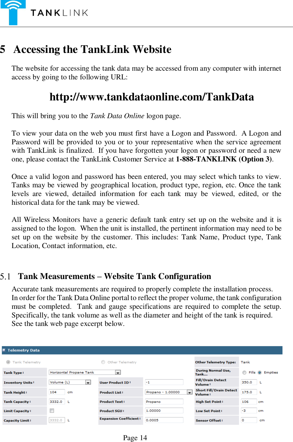
Exhibit D Users Manual per 2 1033 b3

   DRAFT COPY 90 Series  Wireless Remote Tank Monitor                   HOST AND CLIENT CONFIGURATION  Document Rev. - Document No. 910-00017 January 4, 2016
     Page 2
     Page 3 Table of Contents  Contents FCC Statement ..................................................................................................................4 WARNING! – For Your Safety .......................................................................................5 1 Revision History ............................................................................................................6 2 Series 90  Introduction ...................................................................................................7  Overview ................................................................................................................7  For Your Safety .......................................................................................................7 3 Theory of Operation ......................................................................................................8  Transfer of Data ......................................................................................................9  Product Highlights ..................................................................................................9 4 Installation .....................................................................................................................9  Safety Precautions ...................................................................................................9  Initial Inspection ................................................................................................... 10  Installation Precautions ......................................................................................... 10 4.3.1 Installation of the 90 SERIES  ...................................................................... 11  System Control Drawing for the Uplink Model Only ............................................. 12 5 Accessing the TankLink Website ................................................................................. 14  Tank Measurements – Website Tank Configuration .............................................. 14  Setting the Number of Callouts per Day ................................................................ 15 5.2.1 Scheduled Callouts ....................................................................................... 15 5.2.2 Call On % Change ........................................................................................ 16 5.2.3 Affectivity of Callout Setting Changes or Programming ............................... 16  Normal Operation.................................................................................................. 16 6 Series 90  Specifications .............................................................................................. 17     Cellular Specifications ................................................................................................. 17 7 Servicing and Troubleshooting .................................................................................... 18  Error Codes ........................................................................................................... 18  Battery Replacement ............................................................................................. 20  Troubleshooting .................................................................................................... 21  Obtaining Technical Support ................................................................................. 21 8 Replacement Parts ....................................................................................................... 22 9 Terms and Conditions of Service ................................................................................. 22 10 Product Warranty and Notices ..................................................................................... 24
     Page 4   FCC Statement  This device complies with Part 15 of the FCC Rules. Operation is subject to the following two conditions:  (1) This device must not be allowed to cause harmful interference (2) This device must accept any interference that may cause undesired operation.                                   IC STATEMENT  This device complies with Industry Canada license-exempt RSS standard(s). Operation is subject to the following two conditions: (1) this device may not cause interference, and (2) this device must accept any interference, including interference that may cause undesired operation of the device.  Le présent appareil est conforme aux CNR d'Industrie Canada applicables aux appareils radio exempts de licence. L'exploitation est autorisée aux deux conditions suivantes : (1) l'appareil ne doit pas produire de brouillage, et (2) l'utilisateur de l'appareil doit accepter tout brouillage radioélectrique subi, même si le brouillage est susceptible d'en compromettre le fonctionnement
     Page 5       WARNING! – For Your Safety  For Your Safety:  Read  these  installation  and  operation  instructions  carefully.  Failure  to  follow  these instructions may result in death or serious injury.  Caution: The battery pack used in this device may present a fire or chemical burn hazard if mistreated. Do not recharge, disassemble, heat above 100°C (212°F) or dispose of in fire. Replace battery pack with TankLink P/N 394-00023 only.  Use of another battery pack may present a risk of fire or explosion.  Only qualified service personnel must install or repair this equipment.  Do not disassemble the housing unless the area is known to be non-hazardous. Remove the electronic enclosure from the hazardous area prior to changing the battery pack.  Refer to section 3 for installation details.  Substitution of parts may impair the intrinsic safety of this equipment.  This equipment must be installed in accordance with local requirements and the National Electric Code.     Copyright 2015 TankLink Inc.   No part of this document may be copied, reproduced, or translated without the prior written consent of TankLink Inc.  No part of this document may  be stored or transmitted in any electronic form without the prior written consent of TankLink Inc. TankLink Inc. has made every effort to ensure the accuracy and completeness of this document.  However, as we are continually making improvements to our products, we cannot guarantee the accuracy of this document.  We will not be liable for any inaccuracies, omissions, or future changes. TankLink and the TankLink logo are registered trademarks of TankLink Inc.  All other trademarks referenced herein are the properties of their respective organizations.
     Page 6 1 Revision History  Version Date Description of Changes   January 4, 2016 Draft Release
     Page 7 2 Series 90  Introduction   Overview The Series 90 are wireless communication devices that provide quick and easy access to remote tank information such as product level and volume.  Intended for supplier-managed inventory programs, the Series 90 utilizes the latest internet and cellular technologies to provide  instant  access  to  inventory  information  around  the  globe.    Coupled  with  the TankLink® information website, the Series 90 can provide a tremendous advantage over conventional systems for inventory management, asset control, or information exchange.  The  Series  90  is  also  available  in  Host  and  Client  Model  configurations.  This  is advantageous where a number of tanks are collocated together such that a single Host unit may communicate with several Clients. The advantage is that only one Cellular radio can perform all communications with the TankLink Data Center for itself and its Clients. Thus simplifing installation and maintenance. Contact TankLink sales for more information.     For Your Safety  Read  these  installation  and  operation  instructions  carefully.  Failure  to  follow  these instructions may be dangerous or illegal.  Only  qualified  service  personnel  must  install  or  service  this equipment.
     Page 8 3  Theory of Operation    Figure 1
     Page 9  Transfer of Data  The  Series  90  communicates  to  the  TankLink®  Data  Center  using  a  wireless  cellular technology called GSM Short Message Service. This technology allows the unit to transmit digital data to the TankLink®  Data Center using the  existing  network of  GSM cellular towers deployed throughout North America and around the globe.  In order to transmit a data packet, the local GSM cellular carrier must provide SMS (Short Message Service).  Once the data is at the TankLink® Data Center, it may be viewed over the internet using a standard  web  browser  (i.e.  Microsoft  Internet  Explorer  or  FireFox),  downloaded  to applications such as Microsoft Excel, or it may be used to trigger events such as e-mail or a page to a local sales or service representative.  To access the data provided by the Series 90 unit, a current monitoring service agreement with TankLink is required. For assistance with accessing the Tank Data Online® website, contact TankLink Customer Support at 1-888-TANKLINK (Option 3) or go to www.tankdataonline.com\TankData.    Since the 90 SERIES  is a wireless device, care must be taken when installing the unit to minimize interference from nearby equipment or structures.  For installation guidelines, please refer to Chapter 4.      Product Highlights  No telephone line is required for communication  No external power source is required  Fast, simple installation  Flexible sensing technology   Fixed monitoring costs  Unlimited applications  Easy removal of electronics for battery replacement in a location free of hazardous vapors  Host and Client configurations   4 Installation    Safety Precautions This product must be installed and maintained in strict accordance with the National Electrical Code and any other applicable local electrical codes       For Uplink models only refer to the System Control Drawing (906-00017) shown in this section of the manual for specific installation information. Failure to observe this warning could result in serious injuries or damages.
     Page 10 GENERAL Warnings!  Caution:  The  battery  pack  used  in this  device  may present  a  fire  or chemical  burn hazard  if  mistreated.  Do  not  recharge,  disassemble,  heat  above  100°C  (212°F)  or dispose of in fire. Replace the battery pack with Telular part number 394-00023 only.  Use of another battery pack or power source may present a risk of fire or explosion.  Do not install Series 90  battery pack where hazardous vapors are present.  Do not use the Series 90  where blasting is in progress.  Service may be limited in areas that do not have GSM cellular coverage and support SMS (Short Message Service).  Canadian Safety Agency (CSA) has not tested the performance or reliability of the Global Positioning System (GPS) and/or Enhanced 911 (E911) hardware, GPS and/or E911 operating software or other GPS and/or E911-related aspects of this product. CSA has  only  tested  for the  explosion,  fire,  shock  and  casualty  hazards  required  by  the applicable  hazardous  locations  standards.  CSA  certification  does  not  cover  the performance  or  reliability  of  the  GPS  and/or  E911  hardware,  GPS  and/or  E911 operating software or other  GPS  and/or  E911-related aspects of  this  product.  CSA MAKES  NO  REPRESENTATIONS,  WARRANTIES  OR  CERTIFICATIONS WHATSOEVER  REGARDING  THE  PERFORMANCE  OR  RELIABILITY  OF ANY GPS AND/OR E911 RELATED FUNCTIONS OF THIS PRODUCT.    Initial Inspection When you receive the Series 90  unit, thoroughly inspect it for any damage which may have occurred during shipping.  If there is any damage to the Series 90 , contact TankLink Customer  Support  at  1(888)-TANKLINK  (option  3)  as  soon  as  possible  or  email  to TelemetrySupport@telular.com.  Locate the packing checklist in the shipping container.  Check for any missing items before you begin installation of the Series 90 .  Tools Required for Installation:  Phillips Screwdriver   1.0 Tip (1/8”D), 2-1/2" Lg. Phillips Blade)  2.2 Tip (1/4"D), 4 Lg. Phillips Blade  Adjustable Slip-Nut Wrench  o 1”-3” jaw cap. X 10-1/4”lg or o Adjustable Pliers 1”-3” jaw cap. (Channel-Lock type)  Open End Wrench (3/8”)      Installation Precautions The Series 90 remote telemetry unit is installed directly to specific sensor assemblies provided by TankLink.   Do not injure the cable in any way such as tight bends or slicing the outer sheath with sharp objects.
     Page 11 If a tank contains a pump at the bottom with a pipe diameter large enough for the sensor to enter it, it will be necessary to suspend the probe slightly above the bottom of the tank. The same is true if the drain pipe is large enough for the sensor to slip into it. The cable may be coiled up in large diameter coils and secured with a fastener such as a plastic Tywrap. Whatever is used must be appropriate for the chemical in the tank. The coil can be carefully compressed just enough to get through the bung opening. The cable must not be crimped.   4.3.1 Installation of the Series 90      If you installing a Host and Client(s) proceed to install the Host first followed by the Client.   Without removing the Series 90  electronics, carefully connect the battery cable to its mating connector (see Fig. 1).  At this point, the Series 90  electronics is in an active state. The Inventory Request Button (S1) remains active in this state and can be used to request an inventory update at any time.  Upon plugging in the battery the green LED on the circuit card should begin to flash.     Examine the LED sequence and verify proper communications with the TankLink Data Center. (Refer to section 7 which explains the LED light sequence)  Allow the Series 90 to complete the communications process.  This could take several minutes and the LEDs will go dark when the process is complete. If the red LED lights then an error has occurred. See section 7 for error code definitions.   Install the Sensor.   Identify the appropriate 2” NPT bung opening designated to receive the sensor assembly.  Ensure the designated level gauge is properly rated to be installed in the storage vessel based on the commodity stored in the vessel. The cable must be long enough to reach the bottom of the tank.   Remove the bung opening plug or existing level gauge.  Carefully lower the sensor to the bottom of the tank and secure the excess cable if required. The sensor must not be dropped!  Verify the Series 90 makes a proper seal in the bung opening. It is recommended to use Teflon tape around the threads of the Series 90.  Momentarily press the Inventory Request pushbutton (S1). This will initiate a new call sequence.  Verify the green LED pattern and let the Series 90 electronics complete the call sequence.  From an area known to be free of hazardous material, call TankLink Customer Support or access the Tank Data Online web portal to verify the tank level and that the initialization process has successfully completed. Be ready with all applicable tank parameters and desired call data so that customer support can ensure the website is setup properly.
     Page 12  Verify the key calibration parameters are properly configured via the Tank Data Online web portal and verify the level.  Outside the hazardous area call TANKLINK Customer Support at 1(888)-TANKLINK (option 3) or email TelemetrySupport@telular.com.  When all tank parameters have been verified and the level is correct you may close the lid and tighten the two Philips screws securely. This is required to ensure the unit is weather tight. Water or other contaminants entering the enclosure will damage the unit and void the Warranty!
     Page 13
     Page 14  5 Accessing the TankLink Website  The website for accessing the tank data may be accessed from any computer with internet access by going to the following URL:  http://www.tankdataonline.com/TankData  This will bring you to the Tank Data Online logon page.  To view your data on the web you must first have a Logon and Password.  A Logon and Password will be provided to you or to your representative when the service agreement with TankLink is finalized.  If you have forgotten your logon or password or need a new one, please contact the TankLink Customer Service at 1-888-TANKLINK (Option 3).   Once a valid logon and password has been entered, you may select which tanks to view.  Tanks may be viewed by geographical location, product type, region, etc. Once the tank levels  are  viewed,  detailed  information  for  each  tank  may  be  viewed,  edited,  or  the historical data for the tank may be viewed.  All Wireless Monitors have a generic default tank entry set up on the website and it is assigned to the logon.  When the unit is installed, the pertinent information may need to be set up on the website by the customer. This includes: Tank Name, Product type, Tank Location, Contact information, etc.     Tank Measurements – Website Tank Configuration Accurate tank measurements are required to properly complete the installation process.   In order for the Tank Data Online portal to reflect the proper volume, the tank configuration must be completed.  Tank and gauge specifications are required to complete the setup.  Specifically, the tank volume as well as the diameter and height of the tank is required. See the tank web page excerpt below.
     Page 15    Setting the Number of Callouts per Day   The Series 90  has enhanced the user’s ability to customize the scheduled inventory Callouts of the unit under the particular tank’s “Tank Setup Tab” in the Call Schedule Panel.  Additionally, the Call on % Change Callout is also separately selectable under the tank’s Tank Alarms Tab in the Device Alarm Setup panel.  The tank’s default setting will be a single Callout per day between 12:00 AM and 12:59 AM. This setting is automatically active upon installation without any further programming of the Call Settings on the tank’s Tank Setup Tab.  5.2.1 Scheduled Callouts  There are 4 specific parameters for the scheduled Callouts that need to be programmed as indicated below:    Start Time allows the selection of a specific time, within a 1 hr. window, in which the tank will call out the first time for that day (that 24 hour period). The selection is made using the Drop Down-List Box where all the valid selections are listed. This sets the starting time or first callout from this tank for the day.  Call Interval allows the filling in of the time spacing, in hours, between subsequent Callouts from the tank. Select the desired interval from the drop-down list-box.  Calls Per Day allows the selection of the specific number of Callouts for a given day. The selection is made using the drop-down list-box where all the valid selections are listed.    Day Schedule allows the selection of the specific days of the week when the Callouts should occur. Each day of the week can be activated or deactivated by clicking on the Checkbox independent of the others.   Note: that the selection of the first three parameters above are inter-related so that the Callouts can occur in a single 24 hour period. Hence it is important to select the Preview Schedule which brings
     Page 16 up a summary of the settings made and will display an error indication should the selections conflict with each other.  Preview Schedule  allows one to view the settings programmed as interpreted by the program and also receive an error warning on the settings if conflicts exist. It is advisable to always select this after programming or changing the four scheduled Callout parameters above thereby eliminating any unintentional errors.   5.2.2 Call On % Change   Call On % Change  allows the Callout based on a % inventory change, increase or decrease, regardless of the scheduled Callouts programmed above. This Callout is not dependent on the scheduled Callout settings above. This provides the former feature of inventory Callout based on inventory change that was part of the scheduled Callout programming with the Jumpers.  5.2.3 Affectivity of Callout Setting Changes or Programming  All changes to a tank’s Call Schedule (and other parameters) will remain “Pending” until the Call Schedule is transferred to the Series 90 device.  Pending “Call Schedule” updates are by default transferred to the Series 90 device on Sunday’s and each time a manual start-up (reset) action is performed.  Following a successful transfer of “Pending” device configuration changes, the website transitions the device to an “Updated” state.  User with “Diagnostic” privileges can view the device state from the Tank Details page under the diagnostic panel.  A device is considered updated when Transmit Sequence count is equal to the Acknowledged Sequence count.  Call TankLink Customer Support (1-888-TANKLINK) for more information.     Normal Operation After communication has been established, and the tank information has been given to the TankLink Data Center, the Series 90 will continue to transmit data based upon the number of calls scheduled. This tank data can be accessed thru the internet.  Refer to the next chapter of this manual for information on accessing the data.  The  real  power  behind  the  TankLink®  Inventory  management  system  is  the TankDataOnline.com website.  On this website, you may view the current level and status of your devices using a standard web browser (i.e. Microsoft Internet Explorer® or FireFox ®), download your historical data to applications such as Microsoft Excel®, or set up alarm levels  to  automatically  trigger  events  such  as  an  e-mail  to  a  local  service  or  sales representative.  The TankDataOnline.com is a secure website which utilizes the latest in internet encryption technology to ensure that your data stays confidential.  It is constantly being upgraded and new features are being added periodically.
     Page 17  6  Series 90 Specifications   Performance Specifications  Output Voltage (Nominal)  Nominally 24V  5% Output Current (Nominal)  Rated from 0 – 50 mA Load Regulation  0.5% from a 30 mA load Ripple  50 mV Peak-to-Peak Output Short Circuit Protection  Output is current limited to 50 mA Accuracy  ± 1% of Span – dependent on Sensor Spec.                 Hardware Specifications  Sensor Assemblies  Differential Pressure measurement type.      Housing  Weatherproof; UL recognized (UL94V-0); flame-retardant glass-filled nylon or Polypropylene or Stainless Steel    Unit Gross Weight  Without Sensor Assembly: 2.0 lbs. (0.91 kg)   Battery Type  6V – Approved TankLink Battery Pack, P/N 394-00010. Expected Battery Life  One call out per day – up to 20 months Three call outs per day – up to 14 months.  Up to three years for Clients  Environment Storage Temperature Range  -40˚F to 185˚F (-40˚C to 85˚C) Operating Temperature Range  -4˚F to 104˚F (-20˚C to 40˚C)  Cellular Specifications Type  GSM – 3G  Frequency                    850 (824 – 894) MHz and                                             1950 (1850 – 1990) MHz
     Page 18 7 Servicing and Troubleshooting    Error Codes    On a Host device a normal LED  light sequence consists of a number of Green LED (Light Emitting Diode) flashes whenever you plug in the battery or push the Inventory Request button (S1). Following the initialization period the Red and Green LED will flash  alternately.  During  this  time  communicaton  is  occurring  between  the Host/Client(s).   After a few seconds the LED should blink more slowly. This indicates it is talking with the Cellular Network. Next the light stops blinking and stays on continuously. The Series 90    is  now  transmitting  information to  the  Network.  This  part  can take  a  couple  of minutes. Once the process is finished the light will blink quickly and go off.   If an error occurred during the process the red light would appear and the green light would go out. After a short pause the green light would blink indicating one of the error codes shown below.  On a Client device the LED sequence is shorter. Upon pressing the start button the green LED will blink for two seconds and following that initialization period the red and Green LEDs  will  blink  alternately.  This  indicates  the  Client  is  attempting  to  establish communication with a Host within range.  If the data transmission was not successful, a red LED will light and remain lit while the green LED flashes the error codes below.  Host Operation Number of Green Flashes  Error Code Description 4 Cellular Service Error:  The unit did not detect cellular service.  Verify that there is service in the area using the  technique  in Section 4.2 or check GSM coverage information on Websites in Section 4.6. Ensure that the antenna is tightly connected to the unit and is vertical.  5 Cellular Busy Error:   The Series 90 could not transmit because the cellular network is busy.  Re-try data transmission. 6 Radio Respond Error:  The Series 90’s  wireless  transmitter  did  not respond to the command.  Re-try a data transmission.    If this problem continues, replace the Series 90 unit. 7 Low  RSSI  Error:    The  data  transmission  failed  due  to  low  signal strength Error Code 7 in Section 7.1.  Apply the technique indicated in Section  4.3  to  establish  the  best  location  for  an  external  antenna  to improve the signal strength.
     Page 19 8 Failed Transmission Error:  The data transmission failed.  Insert a new battery pack into the unit and re-try a data transmission.  If this problem continues, contact TankLink Customer Service. 12 Poll Failure:  Indicates the Series 90 will retry data acquisition from level gauge before attempting a callout.  Client Operation Number of Green Flashes  Error Code Description 4 Communicaiton Error:  Communication with the Host has failed. 5 6  7
     Page 20  Fig. 1             90 SERIES  Major Components (Host)            Wrap-around Antenna            Caddy Handle   Battery Connector   Inventory Request button (S1)   Battery Hold Down Clip        Battery Replacement  WARNING!  Replace the battery pack with Telular part number 394-00010 only.  Use of any other battery type may present a risk of fire.   Battery Pack, PN #394-00010
     Page 21   Troubleshooting  Nothing happens when the Start switch is pressed.  Remove the caddy assembly from the Hazardous are  Disconnect the battery pack. Wait 30 seconds to initialize the Series 90  memory and connect the battery pack. If the green LED does not come on, replace the battery pack with a new one.  Unit cannot transmit to data center.  Verify that the RSSI is greater than 20.  Verify that there is GSM SMS (Short Message Service) service in the area.  Check for interfering structures such as tanks, buildings, or large equipment.  Reposition the unit if possible.  Verify the Serial Number of the unit on the website.  The level reading is incorrect.  Normally,  all  of  the  sensor  parameters  are  set  up  by  your  TankLink  account representative when the tank is initially configured. On rare occasions, the information may not be correctly entered. If you have verified the tank information and the tank level is still incorrect, there may be several causes for the incorrect reading.    Verify the tank dimensions and high and low set points via the website.  The level reading is correct but volume is off.  Verify the tank capacity. This should be the volume in the tank at the tank height.    Verify that the correct strapping chart is used.    The unit has stopped calling.  Replace the battery pack.     Obtaining Technical Support  If you still are having trouble, contact TankLink Customer Service at:  1-888-TANKLINK    (1-888-826-5546)  You will need the following information:  Series 90  Serial Number (label on the top lid).   Tank location (city/state).  Tank product   REMEMBER:
     Page 22 For  security  reasons,  no  one  from  TankLink  will  ever  ask  you  for  your  logon  or password.   If it should be necessary to return this unit to TankLink for service:  1) You must first obtain a Return Authorization Number from TankLink.  2) This number must be clearly marked on the outside of the shipping container and on the service card which was supplied with the unit. 3) Place the unit with the service card in the original container and ship it prepaid to the address on the service card.  8 Replacement Parts   There are no field serviceable replacement parts within the Series 90  other than the battery.  9 Terms and Conditions of Service This section explains the relationship between the user of this equipment and TankLink Inc.  It explains our respective legal rights concerning all aspects of our relationship, including:  Billing and extra charges  Starting and ending service  Privacy and confidentiality  Early Termination fees ( if applicable )  Limitations of liability and warranty If you use the service or the equipment, or if you pay any amount billed to your account, you consent to the  terms  and  conditions  set  forth  in this  agreement.  If  you  do not agree  with  these terms  and conditions, do not use the service and equipment and notify us immediately to cancel service. 1.  Service This is an agreement for Remote Data Delivery and associated Services between you and TankLink. The term "Unit" is the device which is used to communicate the data to the TankLink Data Center. The term of this agreement depends on the rate plan which was defined in a separate document which is also a part of this agreement. The term of this agreement begins on the date that we activate Service for the Unit. There may be an activation fee associated with the rate plan that you select. In addition, if you select a rate plan which requires a fixed term of more than one month    (such as a one-year plan), you agree to purchase service for the full term. After the term expires, or if there is not a fixed term associated with the service, then this agreement will continue in force until terminated by either party with a 30-day notice. If you select a rate plan with a fixed term of more than  one  month,  you  may  terminate  service  within  the  first  30  days  without  a  penalty.  If you terminate service after the initial 30 days but prior to the end of the term, or we terminate following your default, you will be in material breach of this agreement and agree to pay a cancellation fee as set forth in the rate plan document. 2.  Rates Your Service rates are described in your rate plan document. Your service rate may be based on fees for data communication from your Unit and on fees for remote access to your data via the
              Page 23 internet or other electronic means. Additional fees may be added to your monthly fee for services above your base rate. These additional fees and how they are calculated are described in your rate plan document. 3.  Data Availability and Service Interruptions Wireless Data Transmission Service to the TankLink® Data Center is normally available to your unit when it is within the coverage area of a GSM Cellular Service provider who is under contract to provide GSM SMS Data Service. Service is subject to transmission limitation or interruption caused by weather, terrain, obstructions such as trees or buildings, and other conditions. Service may be limited in areas where GSM SMS coverage is not available or may be temporarily limited due to system capacity limits ( such as during peak usage periods ), system repairs, or modifications. In addition, access to your information via the internet or other electronic means of transmission may be temporarily limited due to system capacity limitations or maintenance. Service interruption may also result from non-payment by you. 4.  Use of Service/Unit You agree not to use the unit or service for any unlawful purposes. You may not resell your service without prior written contractual agreements with TankLink Inc.
              Page 24  10 Product Warranty and Notices  TankLink Inc. (“TankLink”) warrants that the equipment is and will remain free from defects in workmanship and materials for a period of one (1) year from the date of delivery.  Within the warranty period, TankLink shall, without charge for labor or materials, repair or replace  any  defective  components  provided  that  reasonable  care  has  been  exercised  in protecting the equipment from adverse conditions and rough handling.  This warranty does not cover customer instruction, installation, set up adjustments, or signal reception problems. This warranty does not cover cosmetic damage or damage due to acts of God, accident, misuse, abuse, negligence, or modification of, or to any part of this equipment, including the antenna. This warranty does not cover damage due to improper operation or maintenance, connection to an improper voltage supply, or attempted repair by anyone other than an authorized service facility. This warranty does not cover consumables such as a fuse or battery.  This Limited Warranty is in lieu of all other warranties, express or implied (including implied warranties of merchantability and fitness for a particular purpose), and of all obligations or liabilities of TankLink for damages, including but not limited to consequential and incidental damages, arising out of or in connection with the use or performance of the equipment.  TankLink shall not be liable for any damages or loss arising from the use of the data from this equipment or the TankLink.com website.

Navigation menu