Ten Tec 68FTT416 Amplifier User Manual
Ten Tec Inc Amplifier Users Manual
UserManual.wiki
>
Ten Tec
>
68FTT416 User Manual
>
Users Manual
Contents
1.
Users Manual
2.
User Information
Users Manual
Navigation menu
Upload a User Manual
Namespaces
Wiki Guide
HTML
PDF
Info
Views
User Manual
Discussion / Help
Navigation

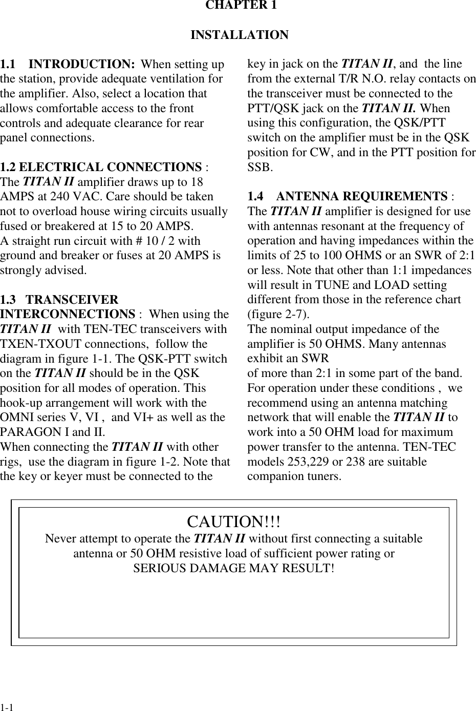
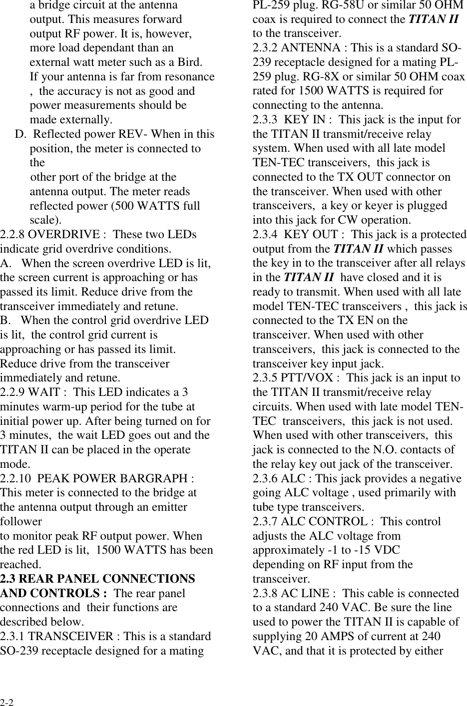
![4-1CHAPTER 4MAINTENANCE AND TROUBLE SHOOTING4-1 INTRODUCTION If you encountera problem , the troubleshooting hintslisted in TABLE 4-1 below will helpisolate the nature of the problem.4-2 MAINTENANCE The amplifiercompartment , particularly areas aroundhigh voltage components should becleaned frequently enough ( using a softbristled brush and vacuum cleaner ) toprevent visible accumulation of dust. DONOT blow air directly into the fan input:this con over rev the motor and damagethe bearingsSYMPTOM POSSIBLE CAUSE/CURE1. Will not turn on: nothing happenswhen the ON switch is activated. A] Fuse missing or open.B] House wiring incorrect or breaker open.C] Power cable to amplifier disconnected.D] Fuse on HV-AC board (81810) open.E] Problem with low voltage power supplyon QSK board (81814)2. Lights turn on but no high voltage,relays do not close. A] Interlock open, cover not tight3. Relays K2 and K3 on HV-AC board(81810) close but relay K1 does not.Plate Voltage drops when RF is applied.A] Q1 ON 81810 HV-AC BOARD ISdefective .B] K1 on 81810 is defective.4. Relays K1, K2, K3 on 81810 HV-ACboard close but no high voltage at turnon.A] K2 , K3 defective.B] HV short to ground.C] High voltage transformer disconnected.D] High voltage bridge open.CAUTION: NEVER TRUST ONLY ONEHV METERING CIRCUIT. THERECOULD BE HV PRESENT BUT THEMETER DOESN’T REGISTER IT.ALWAYS DOUBLE CHECK WITH ANEXTERNAL HV METERTABLE 4-1 TROUBLE SHOOTING HINTS](https://usermanual.wiki/Ten-Tec/68FTT416.Users-Manual/User-Guide-7164-Page-19.png)
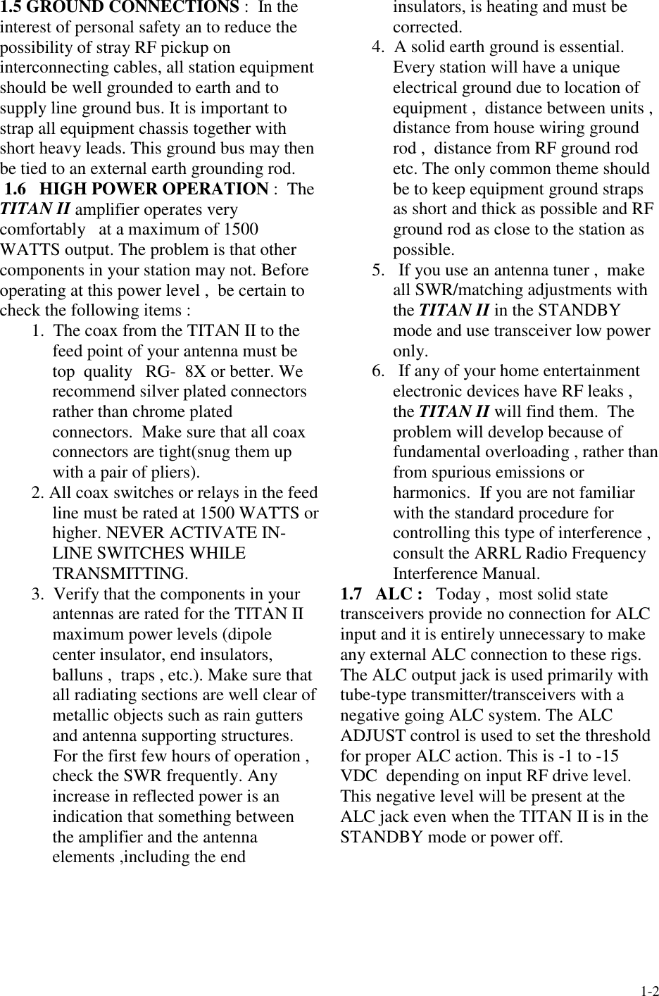
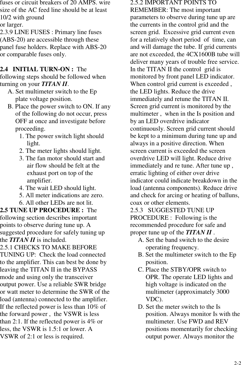
![4-2TABLE 4-1 TROUBLE SHOOTING HINTS ( Continued)5. Relays K1, K2, and K3 close at turn on ,but line fuses blow. A] High voltage at crowbar or elsewhere.B] Shorted tube.C] Leaky electrolytics in high voltagesupply.6. Amplifier won’t drive , zero grid and platecurrent , High input SWR . A] Defective cable from transceiver toamplifier.B] Input relay K2 on 81816 SWR boarddefective.C] Input filter on 81811 input matchingboard loose or damaged.7. Grid over drive led lights with no drive. A] Q7 on 81815 shorted or leaky.B] Shorted or leaky tube.8. Screen over drive led lights with no drive. A] R23 on 81815 board open or increased invalue.B] Low or no high voltage. TURN OFF THEAMPLIFIER IMMEDIATELY.9. Amplifier difficult to drive , little or nooutput , high plate current (may beaccompanied by a “frying sound”).A] Band switch in wrong position.B] Excessively high load SWR.C] Defective output relay on 81816 SWRboard.D] Arcing in tank circuit or antenna feedline.10. Excessive plate current in receive mode. A] Defective bias circuit on 81814 board.B] Shorted grid /cathode in tube.11. Transceiver does not key using key-in/key-out loop. A] Key-in and key-out lines reversed atamplifier or at Transceiver.B] Defective key line cables.C] Defective relay control circuit on 81814QSK board.12. Transceiver stays keyed in receive mode.May be accompanied by loss of receivesignal.A] Relay K1 on 81816 SWR board stuck.B] Shorted key-in or key-out cable.C] Defective relay control circuit on 81814QSK board.](https://usermanual.wiki/Ten-Tec/68FTT416.Users-Manual/User-Guide-7164-Page-20.png)