Tenvis Technology Co PT7131W IP CAMERA User Manual manual
Tenvis Technology Co Ltd IP CAMERA manual
User Manual
CAMERA SETUP continued
Flush ARP Buffer
ARP stands for Address Resolution Protocol. It is used to associate a layer 3 (Network layer) address
(such as an IP address) with a layer 2 (Data Link layer) address (MAC address). When a wired
network and a wireless network of the camera both use the same fixed IP address, a problem may
occur where connections to web pages will time out and fail. Use the Flush ARP Buffer to clear the
ARP cache and fix the error.
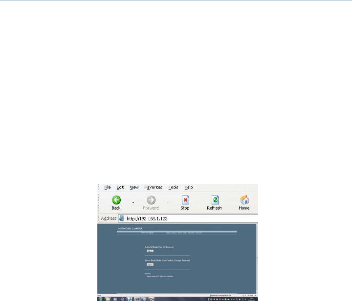
5. Access the IP camera through the IP Camera Tool or IE directly. Either:
s Double click the IP address of the IP camera listed in the search result window. Internet Explorer will be
opened automatically and display the camera login page.
Access the camera via the Internet Explorer browser directly by typing in the camera’s IP address. In the window
that appears, click the ‘Sign in’ button as shown below:
6. The Camera Login page will pop up. Enter your account and password on the login page.
By default administrator’s username is: admin and no password. Click Sign in to enter the
monitoring page. You can enter the page as an Administrator, Operator or Visitor. Each type of user
will allow different levels of access on the web browser interface. Read below for more information
on the access rights and user interface.
Visitor: In this mode, you can only view.
Operator: You can control the image setting of IP Camera and set some parameters.
Administrator: You can setup the advanced configurations of the IP Camera.
7. If you are using a PC, follow the top link for IE Browsers. This will activate ActiveX which allows
access to additional functions of the user interface.
If you are a Mac user, you can view the camera via the second link, Server Push Mode. This web
browser mode features limited functionality but allows Live View and Image Snapshots.
CAMERA SETUP continued
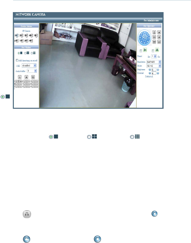
Main User Interface (as seen in Internet Explorer)
Device Status
Indicates the number of cameras connected on the network.
For Viewer
Allows you to view Full Screen or in Split Screen. Select the icons according to the view preferred.
For example: Select for Full Screen, for Quad view or for Multi Split Screen.
Add timestamp on record
When checked, a timestamp will be added in the bottom right corner of recorded videos.
OSD (On Screen Display) for Multi-Device Settings
Display the date and time on the video. You can disable the OSD function.
Audio buffer
Set the audio buffer time in sconds.
Audio switch
Click to enable the audio stream for the camera. The icon will change to . Click this to stop
the audio.
Record
Click icon to go into Record mode. Click to stop. (Audio recording is active if audio is on).
CAMERA SETUP continued
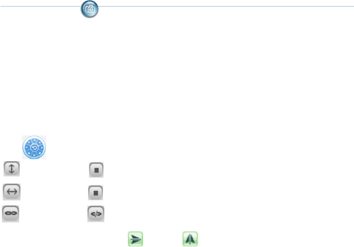
Snapshot: Click the icon to take a snapshot image.
Note:
Recorded video file names will be saved in the format: CameraName_ Current time.
For example: IPCAM_20081211134442. This recording is from the camera called IPCAM and the
recording ‘end’ time was 13:44:42 on December 11, 2008.
For operator
When you login as an Operator or Administrator, you can enter the ‘For Operator’ page.
Mirror
Click the icons to see the horizontal or vertical mirror image.
Resolution
Select either VGA (640x480) or QVGA (320x240).
Work mode
Select either 50Hz, 60Hz or Outdoor.
Brightness and Contrast parameters
Click the + or - icons to adjust the brightness and contrast of the camera image.
Default All
Click to return the settings to the factory defaults.
For Administrator
When you login as an Administrator, the ‘For Administrator’ functions are enabled.
Device Info - You can find information about the camera such as the Device ID, Firmware Version
and Embeded Web UI Version.
Alias Settings - You can change the name of the IP camera.
Data & Time Settings - Set the time and date.
Pan Tilt
Click to control the camera up or down and left or right
Vertical patrol Stop vertical patrol
Horizon patrol Stop vertical patrol
Switch on Switch off
CAMERA SETUP continued
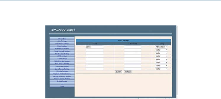
User Settings - You can configure up to 8 user names and passwords and the level of users as
Administrator, Operator or Visitor.
Administrators can:
Set Record Path - Click ‘Browse’ to choose the recording path of where video files will be saved.
Set Alarm Record Path - Click ‘Browse’ to choose the alarm recording path.
Note:
1. The default path for saving files is C:\Documents and Settings\All Users\Documents.
2. In Windows Vista, there are two points you need to notice:
s Vista’s Security level is higher than Windows XP/2000. For the ‘Set Record Path’ function, you will need to
add the add the Device IP address to IE’s ‘Trusted sites’ first. To do this go to: Tools > Internet Properties >
Security >Trusted sites > Sites > Add. In Vista, there is a prompt to add Trusted sites when the Set Record/
Alarm Record path is clicked.
s You cannot set the Windows System Root Directory as you will do for the Record/Alarm Record Path. This
prompt only pops-up in Vista.
UPnP Settings - Access this page to make sure the UPnP Status is working.
Upgrade Device Firmware - Upgrade the camera’s Firmware and device embeded web UI software on
this page.
Restore Factory Settings - Restore factory settings of the device.
Reboot Device - Reboot the device.
CAMERA SETUP continued
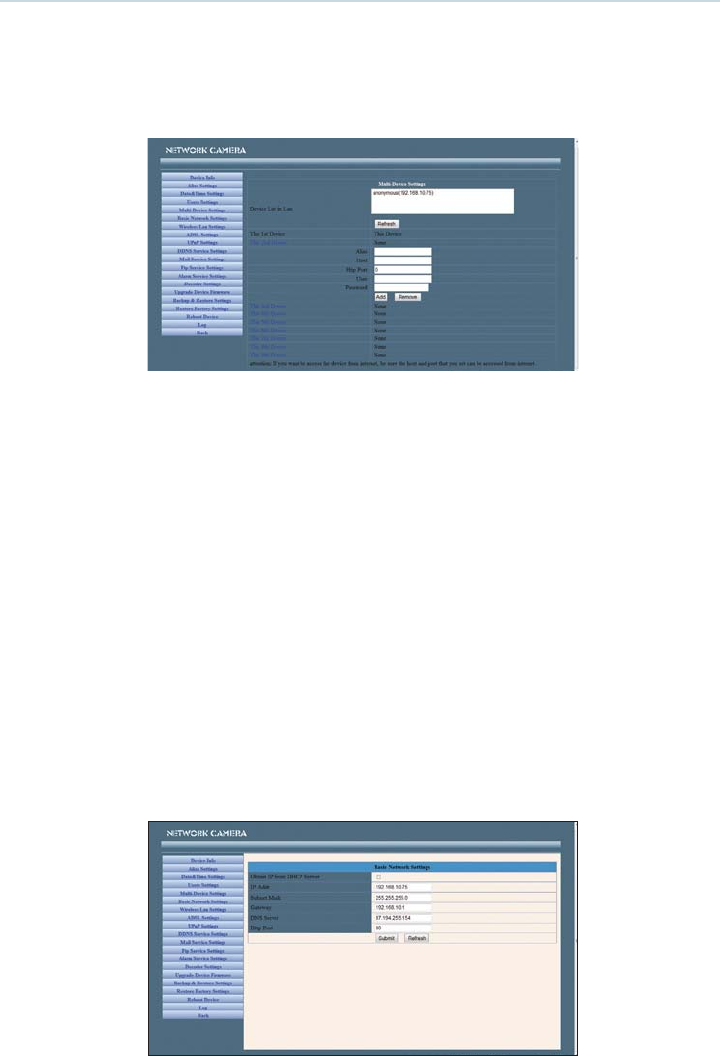
Multi-Device Settings
In the Multi Device Settings page, you can see all devices searched in the LAN.
The ‘1st Device’ is the default IP camera. You can add more cameras to the list in the network for
monitoring. The web browser software supports up to 9 IP cameras simultaneously.
To add cameras to the LAN
Click ‘The 2nd Device’ and double click the IP camera from the ‘Device List in LAN’. The Alias Host and
HTTP Port will fill in automatically. Enter the correct User Name and Password then click ‘Add’. Add more
cameras in the same way.
To add cameras to the Internet
Firstly, make sure the camera added can be accessed on the Internet with the IP address or DDNS domain. (as:
http://202.96.133.134: 9008 or http://ipcamera.dyndns.org:9008).
Enter the Host in the format: 202.96.133.134 port:9008 or Host: ipcamera.dyndns.org port:9008. Enter the
correct User Name and Password then click ‘Add’. Add more cameras in the same way.
Basic Network Settings
If the router that the IP camera connects to has a DHCP function, you can choose ‘Obain IP from
DHCP Server” and fill in the network parameters manually.
HTTP Port - In most cases, you can leave this value as 80, however, if your Internet Service Provider blocks this
port, you may have to switch to another port number such as 8005.
CAMERA SETUP continued
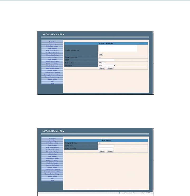
Wireless LAN Settings
Enter the wireless settings page of the Wireless Router to find out the SSID, Channel, Encryption and
Authentication details. This product supports WEP and WAP security encryption.
ADSL Settings
When connected to the Internet through ADSL, you can enter the ADSL username and password
obtained from your ISP.
DDNS Service Settings
The system supports protocols from some DDNS providers such as dyndns.org. Enter the following
information once the DDNS information has been setup.
User and Password: The User Name and Password used when applying for the domain name.
DDNS Host: The domain name.
DDNS or Proxy Server: If you access the DDNS host through a proxy, you should input the Proxy IP.
DDNS or Proxy Port: The Proxy Port.
antenna port :Female RP-SMA
antenna item : SF-2.4G-SMAG