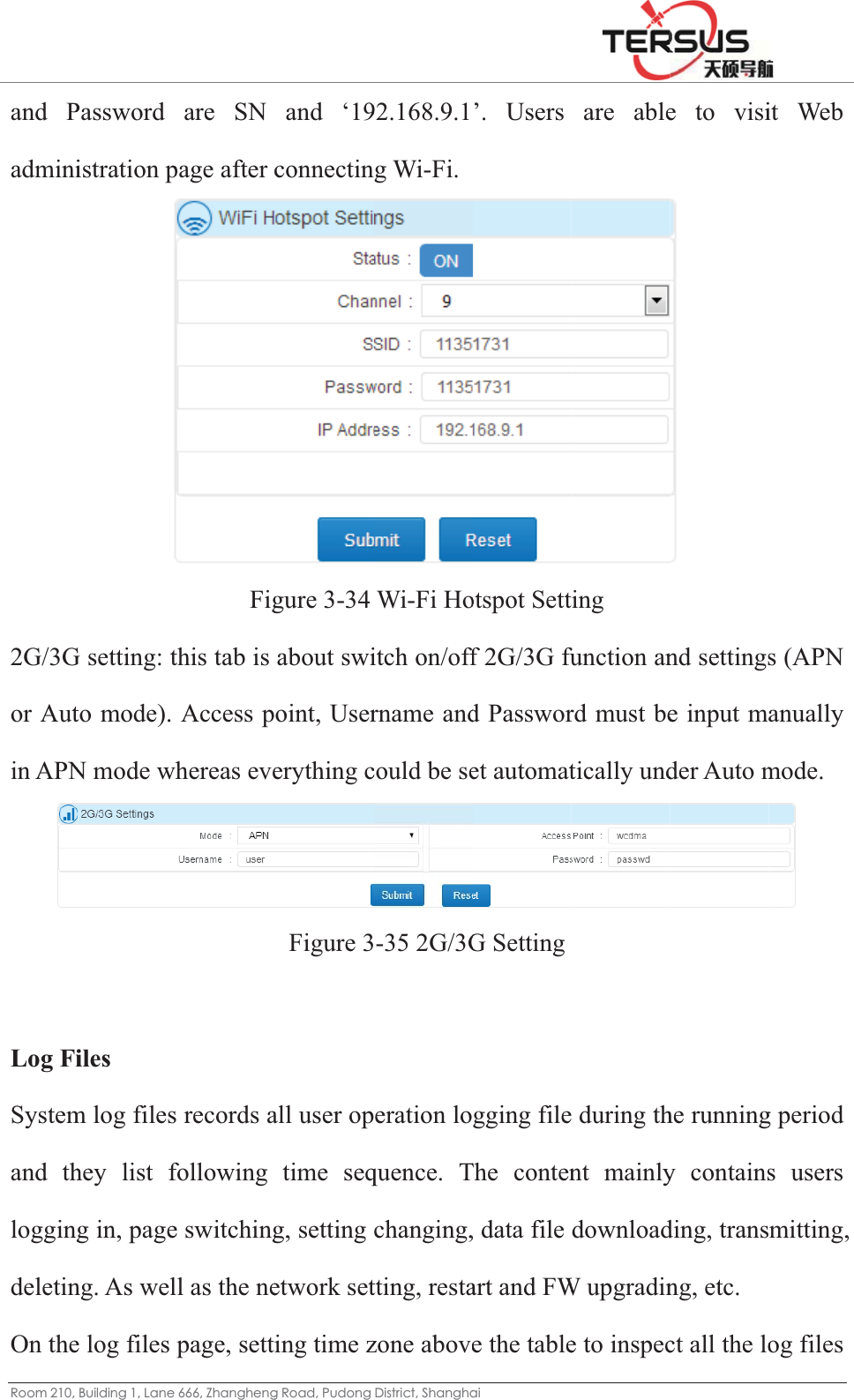
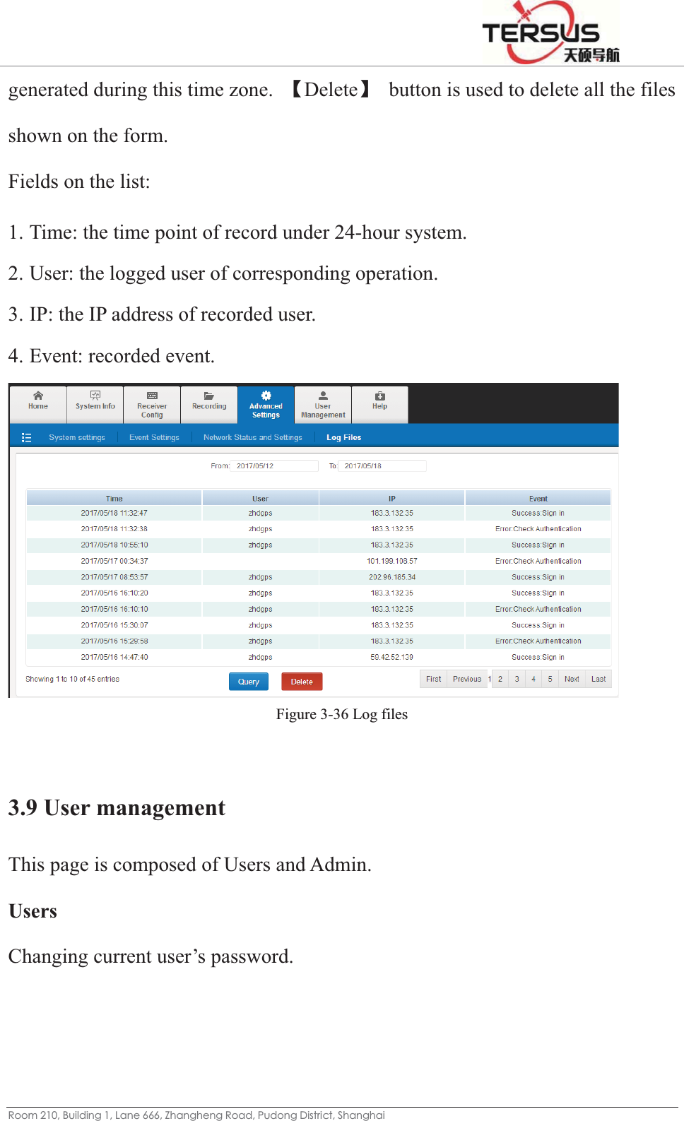
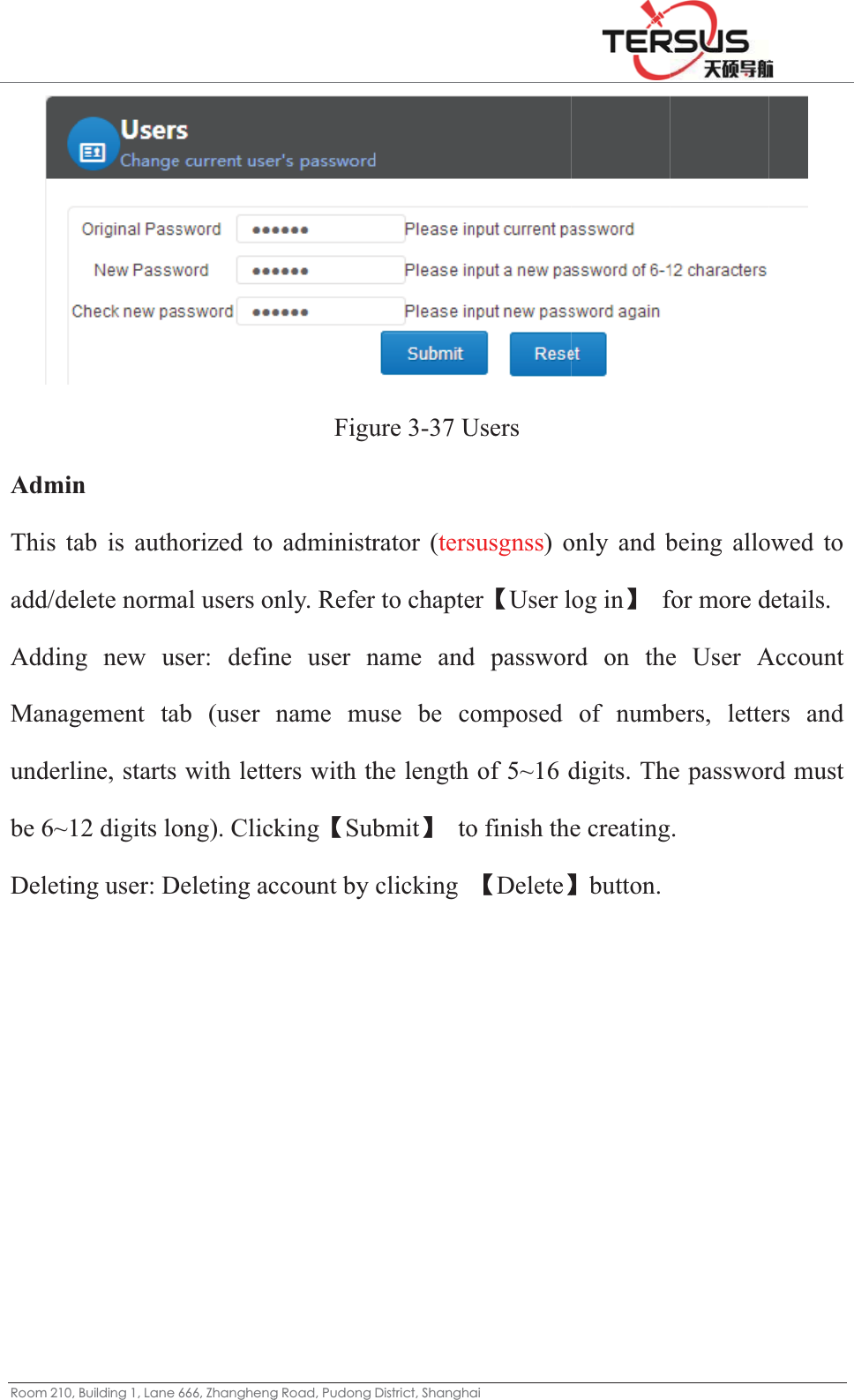
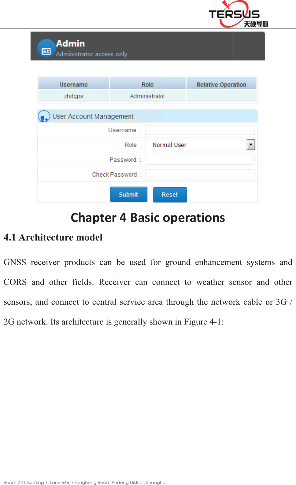
Tersus GNSS MATRIXRTK MatrixRTK GNSS Receiver User Manual 1
Tersus GNSS Inc. MatrixRTK GNSS Receiver 1
UserManual.wiki
>
Tersus GNSS
>
MATRIXRTK User Manual
>
User Manual 1
Contents
1.
User Manual 1
2.
User Manual 2
User Manual 1
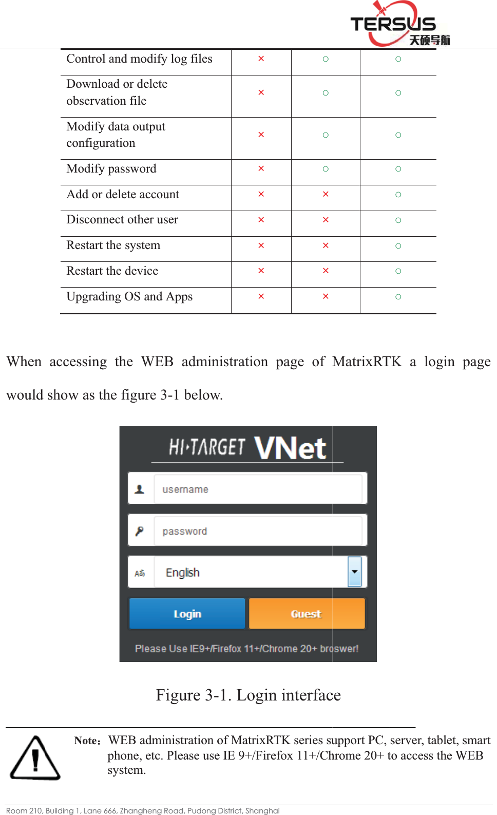
Navigation menu
Upload a User Manual
Namespaces
Wiki Guide
HTML
PDF
Info
Views
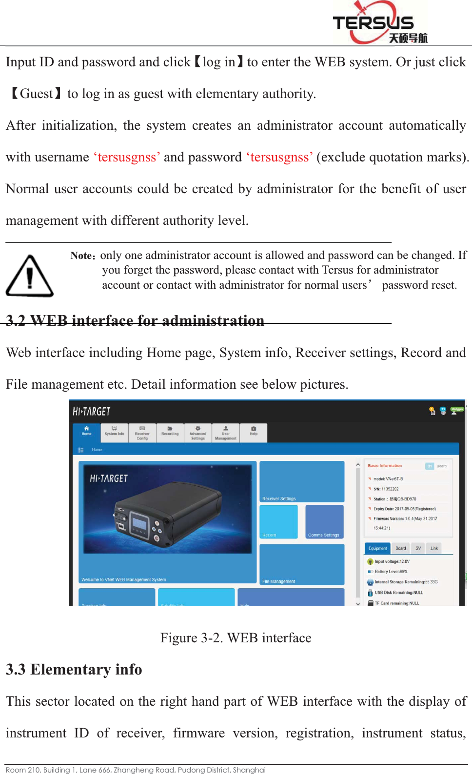
User Manual
Discussion / Help
Navigation

![5RRPEnableheaderoriginadiffereRecordrecordschoosedata reǏStarǏDele3.7 FiFile mstoringaccessiFile lisIn thisdiffere %XLOGLQJ/DQHe the datar, the defaal data andent recordiding meths, etc., whe a file evecord formrtǐǏStopeteǐmeanile manamanagemeng, checkinible for Nst s functionent device.=KDQJKHQJa record anault settingd Rinex fing intervaods are rehen the davery day, emat as needpǐis for tns to eraseagement nt includinng, downlormal usen, users c. Those filJ5RDG3XGRQJnd then sg is _zhd)formats. Aal. ecorded evaily recordevery houded. After the status se one itemng File liloading, ders and Adcan checkles could b'LVWULFW6KDQJKDset the fla), select thAt the samvery day, md mode isur, every twsetting, cswitch of m from exisst and FTdeleting aldministratok and manbe auto deDLag name (he record me time damanual res enabled wo hours lick the [Sexisting trstence TP push full data filor. nage the eleted via sthe file ndata typeata recordcording anto record split a filSubmit] buransmissiounction. Ules. This recordingsetting ‘Auname of d, we provs can be snd planninthe file cle The Selutton. on. Users are function g files stouto clean data file vide the set to a ng time an also lect the able to is only ored in time’.](https://usermanual.wiki/Tersus-GNSS/MATRIXRTK.User-Manual-1/User-Guide-3559791-Page-39.png)
![5RRP2. DataThe padata filfour diclick reset b3. SystUsers restorereceiveRestorpop uprestart Annex%XLOGLQJ/DQHa downloassword isle downloigits with Ǐsubmitǐack to 123tem contrcan remoe factory ser registrare factory sp, click Ǐautomatix [restore f=KDQJKHQJad passws designedoading witdefault seǐ. Clickin34. Figurol otely contsettings, reation and rsettings: CǏOKǐ; Tcally. Aftfactory setJ5RDG3XGRQJFigure 3-ord d for secuthin the usetting 123ng ǏReseure 3-25 Dtrol the reestart, andremote conClick ǏRThe receiveter the resttings]; 'LVWULFW6KDQJKD-24 Systemurity of locse of LED34; to chaetǐ and Data downeceiver vid reset thentrol. Restore Facer will retstart to deDLm settingscal data dD button. Tnge it, enǏsubmitload passwia this wee motherboctory Settiturn to theelete all tdownloadinThis stringnter the neǐ, the paword eb page. oard, upgringsǐ, the factory dthe data ang. Applyg is compoew passwossword woMainly inrading firme dialog bdefault valand settinying for osed of ord and ould be nclude: mware, box will lue and ngs, see](https://usermanual.wiki/Tersus-GNSS/MATRIXRTK.User-Manual-1/User-Guide-3559791-Page-43.png)
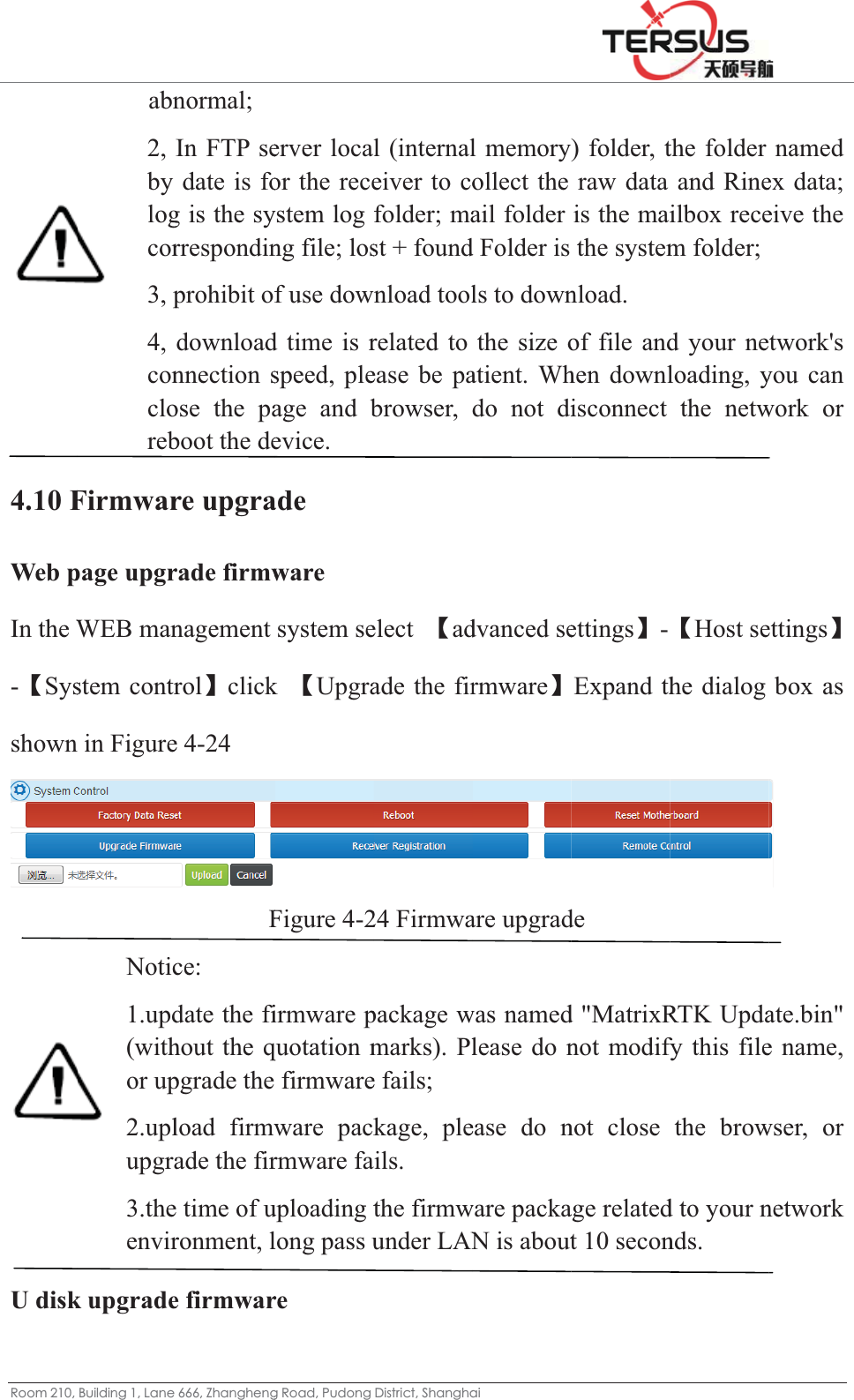
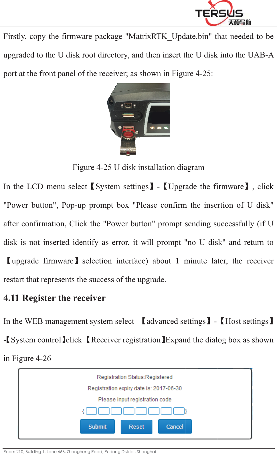
![5RRP b. RebThe reminutec. Rese[reset mrecord d. Upgname "expandǏUploe. ReceOperatf. Rembelow.%XLOGLQJ/DQHboot: Receeceiver we. et the motmotherboare-createsgrade the f"Tersus_Ud the folloadǐ. Foeiver registion See mote contr =KDQJKHQJeiver restawill restarttherboard:ard], and ps the log ffirmware: Update.binlowing inor details, sFigustration: InǏBasic Orol: Click J5RDG3XGRQJart, clickǏt within 1: GNSS bpop-up difile. Upgrade n", cannot nterface, csee ǏBasure 3-26 Unput the cOperationǐ[Remote 'LVWULFW6KDQJKDǏrestartǐ10 secondoard will ialog box the receivbe modificlick [Brosic OperatUpgradingcode and sǐ Chaptecontrol] aDL, pop-up dds and resrestore toto select [ver firmwaied. Click owse] to tionǐėg the firmwsubmit. Rer ǏRegisand the indialog boxstart for o the facto[OK]. Aftare, pay atǏUpgradselect theǏFirmwarware eceiver Restration Rnterface dx to selectapproximaory settingter reset, thttention tode Firmwae file andre Upgradegistrationeceiverǐdisplay shot [OK]. ately 1 gs, click he data o its file areǐ to d click deǐ. n Detail . own as](https://usermanual.wiki/Tersus-GNSS/MATRIXRTK.User-Manual-1/User-Guide-3559791-Page-44.png)
![5RRPor clickClick LogginǏIdennumbeaccordare daishownRecordor reco%XLOGLQJ/DQHk Ǐworkthe buttonng Settingntification ers added bding to acily, man below: d every daord a file e=KDQJKHQJk modeǐ n in thegsǐdialognameǐ by the sysctual needual and ay (24 houevery two FigureJ5RDG3XGRQJ- Ǐdata e upper leg box, ena(the first fstem ) ǏDds, Ǐrecoplanned wurs record hours), ase 4-16 Dai'LVWULFW6KDQJKDrecordǐteft cornerable the sfour digitsData typeǐord intervaways, justwithout bs shown inily Data LDLto set; r of the instatus dials and the lǐ Selectal [S]ǐis rt clickǏsubreak up, on Figure 4Logging Senterface tol to ǏONlast four oǏraw datarecommenubmitǐ. Ror record a-16: ettings o pop upNǐ, set tf the file iaǐ or Ǐnded 1.ǏrRecord wa file everǏData the file is serial Rinexǐ recordǐways are ry hour,](https://usermanual.wiki/Tersus-GNSS/MATRIXRTK.User-Manual-1/User-Guide-3559791-Page-65.png)
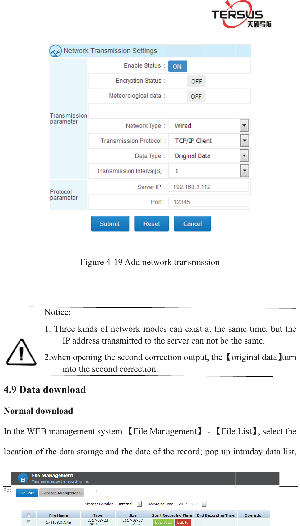
![ 5RRP%XLOGLQJ/DQH=KDQJKHQJ5RDG3XGRQJ'LVWULFW6KDQJKDLLog in WEB management system interface, click the network transmission quick link or click Ǐwork modeǐ - Ǐnetwork transmissionǐto set; Click the button in the upper left corner of the interface , the ǏNetwork Transfer Settingsǐdialog box will pop up, put the state dial to ǏONǐ, ǏEncryption state ǐsets According to the actual need , ǏNetwork ǐ Recommended ǏWiredǐ (wiredǃWi- Fiǃ2G / 3G), Ǐtransmission protocolǐsets according to the actual need˄to understand the transmission protocol, please go to the Ǐwork modeǐ - Ǐnetwork transmissionǐof theǏWEB management system introductionǐ˅, Ǐdata typeǐsets According to the actual needs (choose from raw data, NMEA-0183, correction data, RS232 serial data, RS485 serial port data ) ǏTransmission interval [S]ǐ only the raw data have This option, recommend to use 1 (0.05,0.1,0.2,0.5,1,2,5,10,15,30,60 transmission interval [S] for the user to choose), the server IP , Port, user name and other settings are related to transmission protocol, see the specificǏwork modeǐ -Ǐnetwork transmissionǐof theǏWEB management system introducedǐ; set as shown in Figure 4-19:](https://usermanual.wiki/Tersus-GNSS/MATRIXRTK.User-Manual-1/User-Guide-3559791-Page-67.png)
![ 5RRP%XLOGLQJ/DQH=KDQJKHQJ5RDG3XGRQJ'LVWULFW6KDQJKDL5.4 Network cable connection is normal, but can not log on and visit the VNet series (ground enhancement) Web management system; 1.Make sure whether the computer settings are set according to the network settings and wired network settings in the manual. 2. The computer can ping the GNSS receiver, but can not access; turn off the firewall and anti-virus software. 3.Make sure the IP inputted is correct. If can't just double-click the [power button] to see the current IP address.](https://usermanual.wiki/Tersus-GNSS/MATRIXRTK.User-Manual-1/User-Guide-3559791-Page-76.png)
![ 5RRP%XLOGLQJ/DQH=KDQJKHQJ5RDG3XGRQJ'LVWULFW6KDQJKDL Chapter5Appendix5.1 Reset Major items content The parameters after recovery Reference station Site name HI-TAGET High precision GNSS receiver UTC Time zone UTC+8 Antenna attenuation [dB] 5 Antenna model AT-1200B Antenna high [m] 0 Reference station work mode Rover Ephemeris interval Every 30min Correction data format RTCMV3 Satellite system All open Height cutoff angle 10° Receiver function Storage device Internal storage 2G/3G internet OFF RS232/RS485 Serial port OFF Server port settings 80 Firewall OFF Time input OFF External clock input OFF PPS output OFF FTPPush OFF User Only retain administrator privileges, and restore the default password Automatic cleaning time after full 1 day Small five-core serial port pointing Motherboard 1COM2 Power output OFF Data management Network transmission Delete all Data record Delete all Internal data Delete all Log management Delete all](https://usermanual.wiki/Tersus-GNSS/MATRIXRTK.User-Manual-1/User-Guide-3559791-Page-77.png)
![ 5RRP%XLOGLQJ/DQH=KDQJKHQJ5RDG3XGRQJ'LVWULFW6KDQJKDLAnti-corrosion Satisfy GJB150.11 vibration Satisfy GJB_1032 Impact Satisfy JB/T 9329 30g 3 Times / axis collision Satisfy JB/T 9329 10g 1000 Times Drop Satisfy GB-T2423.8 protect from 1 meter’s drop 5.3 Standard configuration table Item Name Number GNSS Receiver 1 Power Adapter 1 AC power cord 1 Vnet Data cable 1 Direct cable 1 Vnet Packaging cartons 1 Vnet10 Packing lining 1 Ground reinforcement system product manual 1 Aluminum lugs 3 Cross plate head machine wire [M3*6] 3 Warranty Card 1 Factory inspection certificate 1 5.4 Obligations of importers Importers shall indicate on the electrical equipment their name, registered trade name or registered trade mark and the postal address at which they can be contacted or, where that is not possible, on its packaging or in a document accompanying the electrical equipment. The contact details shall be in a language easily understood by endusers and market surveillance authorities.](https://usermanual.wiki/Tersus-GNSS/MATRIXRTK.User-Manual-1/User-Guide-3559791-Page-79.png)