Tersus GNSS MATRIXRTK MatrixRTK GNSS Receiver User Manual 1
Tersus GNSS Inc. MatrixRTK GNSS Receiver 1
Contents
- 1. User Manual 1
- 2. User Manual 2
User Manual 1

5RRP%XLOGLQJ/DQH=KDQJKHQJ5RDG3XGRQJ'LVWULFW6KDQJKDL
MatrixRTK User Guide
Tersus GNSS Inc.
All Rights Reserved

5RRP%XLOGLQJ/DQH=KDQJKHQJ5RDG3XGRQJ'LVWULFW6KDQJKDL
Manual Revision
Filenumber˖
Revision
Date RevisionLevel Description
20170727 1 MatrixRTKUserGuide

5RRP
Intro
d
Welco
m
produ
c
Exper
In or
d
carefu
l
to ww
w
Tips f
o
and
Exclu
s
Befor
e
will h
e
if you
instru
c
operat
i
Tersus
Such
even
b
%XLOGLQJ/DQH
d
uction
m
e to M
a
ct
.
ience Re
q
d
er to he
l
l
ly rea
d
t
h
w
.tersus-
g
o
r safety
u
N
need
s
ion
e
using th
e
e
lp you b
e
fail to
o
c
tion, or
o
i
ng instru
c
is com
m
W
wrong op
b
reaks do
w
=KDQJKHQ
J
Prefa
c
a
trixRT
K
U
q
uiremen
l
p you u
s
h
e instruc
t
g
nss.com
o
u
se
N
o
t
ice: T
h
your sp
e
e
product
s
e
tter use i
t
o
perate t
h
o
perate th
e
c
tion.
m
itted to
c
W
arning:
T
era
t
ion
m
w
n the sy
s
J
5RDG3XGRQJ
c
e
U
ser Gui
d
t
s
e Tersus
t
ion. If yo
u
o
r contact
h
e conten
t
e
cial atte
n
s
, please
c
t
. Tersus
G
h
e produc
t
e
product
c
onstantl
y
T
he cont
e
m
ay make
t
s
tem and
e
'LVWULFW6KDQJK
D
d
e. This i
n
series p
r
u
are unf
a
Tersus T
e
t
s here g
e
n
tion. Ple
a
c
arefully
r
G
NSS In
c
t
accordi
n
wrongly
y
perfect
e
nts here
t
he machi
n
e
ndanger
s
D
L
n
troductio
r
oducts b
a
miliar wi
t
e
chnical
G
e
nerally
a
a
se read
t
r
ead the
o
c
. will not
n
g to the
because
o
product
f
generall
y
n
e damag
e
s
personal
n describ
e
etter, Te
r
t
h the pro
d
G
roup.
a
re specia
l
t
he conte
n
o
perating
assume t
h
require
m
o
f failing
f
unctions
y
are ver
y
e
d, make
safety.
e
s how to
r
sus sugg
e
ducts, ple
l
operati
o
n
ts carefu
inst
r
uctio
n
h
e respo
n
m
ents in
o
to under
s
and perf
o
y
import
a
the data l
o
use this
e
sts you
ase refer
o
ns,
lly.
n
, and it
n
sibilities
o
perating
s
tand the
o
rmance,
a
nt.
o
s
t
,

5RRP%XLOGLQJ/DQH=KDQJKHQJ5RDG3XGRQJ'LVWULFW6KDQJKDL
improve service quality and reserve the rights to change the contents in operating
instruction without separate notice.
We have checked the consistency between contents in instruction and software &
hardware, without eliminating the possibility of deviation. The pictures in
operating instruction are only used for reference. In case of inconformity with
products, the products shall prevail.
Technology and Service
If you have any technical issues, you can call Tersus technology department for
help, we will answer your question in time.
Advice
If you have any comments and suggestions, please call us or Dial the national
hotline: +86-21-58460122. Your feedback information will help us to improve the
quality of the product and service.

5RRP%XLOGLQJ/DQH=KDQJKHQJ5RDG3XGRQJ'LVWULFW6KDQJKDL
MatrixRTKUserManual
Chapter1 Introduction ................................................................................................................ 7
1.1 Introduction .......................................................................................................................... 7
1.2 Features ................................................................................................................................ 7
1.3 Use and precautions ........................................................................................................... 10
Chapter 2 GNSS receiver Introduction ................................................................................... 13
2.1 Front Panel ......................................................................................................................... 13
2.2 Back Panel ......................................................................................................................... 14
2.3 Mainframe .......................................................................................................................... 14
2.4 Button Function ................................................................................................................. 15
2.5 Indicator lights ................................................................................................................... 16
2.6 LCD ................................................................................................................................... 17
2.7 External port ...................................................................................................................... 20
Chapter 3 WEB Administration .............................................................................................. 22
3.1 User login ........................................................................................................................... 22
3.2 WEB interface for administration ...................................................................................... 24
3.3 Elementary info ................................................................................................................. 24
3.4 Home page ......................................................................................................................... 26
3.5 System info ........................................................................................................................ 27
3.6 working mode .................................................................................................................... 30
3.7 File management ................................................................................................................ 39
3.8 Advanced setting ................................................................................................................ 41
3.9 User management .............................................................................................................. 49
Chapter 4 Basic operations ....................................................................................................... 51
4.1 Architecture model ............................................................................................................. 51
4.2 Basic composition and connection .................................................................................... 52
4.3 Connector installation ........................................................................................................ 53
4.4 Network connection ........................................................................................................... 54
4.5 LCD and button operation ................................................................................................. 61
4.6 Set the base station ............................................................................................................. 63
4.7 Add data record .................................................................................................................. 64
4.8 Add network transmission ................................................................................................. 66
4.9 Data download ................................................................................................................... 68

5RRP%XLOGLQJ/DQH=KDQJKHQJ5RDG3XGRQJ'LVWULFW6KDQJKDL
4.10 Firmware upgrade ............................................................................................................ 72
4.11 Register the receiver ........................................................................................................ 73
Chapter 5 Appendix .................................................................................................................. 77
5.1 Reset .................................................................................................................................. 77
5.2 Tersus product technical performance parameters table .................................................... 78
5.3 Standard configuration table .............................................................................................. 78
5.4 Obligations of importers .................................................................................................... 78
5.5 Caution ............................................................................................................................... 80

5RRP%XLOGLQJ/DQH=KDQJKHQJ5RDG3XGRQJ'LVWULFW6KDQJKDL
Chapter1Introduction
1.1 Introduction
This manual mainly introducing GNSS receiver MatrixRTK.
The MatrixRTK Series GNSS reference receiver installed with the
high-performance microprocessors, high-capacity, high-speed flash
memory and battery, multi-communication port and military grade
industrial standard design level. With built-in firewall, data encryption
transmission protocol, make the GNSS receiver more accurate, easy to
use , better availability, more stable operation. On the strength of Tersus’s
sophisticated GNSS technology and the years of experiences in
establishing CORS/VRS system, the MatrixRTK series GNSS reference
receiver will provide you with reliable communication, better
performance, stronger stability and safety.
Notice:
1. The specific configuration is write on the list.
2. Please carefully open the box to confirm. If you find any loss
of this product and accessories, damages, please contact your
local office or dealer immediately.
3. Please read the instruction manual carefully before carrying,
using and handling.
1.2 Features
1.Based on the Linux operating system

5RRP%XLOGLQJ/DQH=KDQJKHQJ5RDG3XGRQJ'LVWULFW6KDQJKDL
Based on the embedded Linux operating system kernel, is a real
multi-user, multi-tasking, multi-platform operating system. With its
system stability, management functions, powerful network; the
MatrixRTK is suitable for a long time unattended continuous work.
2. Excellent GNSS multi-constellation tracking performance
220 Channels with Trimble OEM mainboard, support GPS, GLONASS,
BDS, GALILEO and other global satellite navigation and positioning
system, can maximize the tracking ability of all visible GNSS satellite
signals, thereby improving the measurement accuracy and real-time RTK
measurement performance.
3. 50 Hz updating rate
Support high frequency data updating, data updating rate up to 50 Hz, and
maintain the best observation quality of the data and the independence of
the observation value;
4.Multi-task function
The GNSS receiver can deal with multiple task operations at the same
time and simultaneously download, release different types of RTK or
RTD data while continuously tracking and recording satellite data.
5. Multi transmission mode
With UHF radio, data line Modem, broadband port, Fax Modem, TCP / IP,
built-in 3G / 2G wireless communication function, can use the Internet,
wireless network for data transmission and broadcast differential data.

5RRP%XLOGLQJ/DQH=KDQJKHQJ5RDG3XGRQJ'LVWULFW6KDQJKDL
6.Massive data management function
Built-in 64GB high-performance storage and can support the maximum
of less than 1TB industrial-grade U disk storage or external USB storage
devices; support U disk download, FTP download and remote download;
and the receiver also has a loop storage function.
7.High-precision measurement technology
The Tersus’s sophisticated GNSS technology make sure the accuracy
reaches millimeter, make sure the data have the reliable quality.
8. Excellent compatibility
With excellent compatibility, real-time output CMR, RTCM, RTCMV3,
RTCM32, and other formats of correction data to compatible with third
part CORS system seamlessly, which can be used to new and extend
enhance CORS system. Also output high-precision real-time GNSS raw
data.
9. Remote access function
Easy to using the Network for remote access the reference stations, easy
for remote control.
10. Multi data interface
Equipped with three RS232 ports, two USB ports, one Wi-Fi, one
Bluetooth communication port, one 3G / 2G communication port, one
Ethernet port, one RS485 port, one external clock port, one PPS output
port, fully meet the reference Station requirements.

5RR
P
11.
M
Bu
i
co
n
b
at
t
1.
3
Al
t
on
the
Av
o
Th
e
alu
m
An
ser
v
su
c
1.
D
2.
T
3.
T
4.
C
P
%XLOGLQJ
M
ulti-mo
d
i
l
t
-in larg
e
n
figuratio
n
t
ery, sola
r
3
Use an
d
t
hough th
e
military
s
precisio
n
o
id using
e
Matrix
R
m
inum al
d in ord
e
v
ice life,
c
h as:
D
amp
T
he temp
e
T
he temp
e
C
orrosive
/DQH=KDQ
J
d
e power
e
capacit
y
n
); extern
a
r
and win
d
d
preca
u
e
Matrix
R
s
tandard
d
n
instrume
n
WAR
N
the sp
e
Matrix
R
table.
the recei
v
R
T
K
(gr
o
loy for t
h
e
r to imp
r
please av
e
rature is
h
e
rature is
l
liquid or
g
J
KHQJ5RDG3X
G
supply
y
lithium
b
a
l voltage
d
power s
u
u
tions
R
T
K
serie
s
d
esign, it
n
ts requir
e
N
ING: Th
e
e
cified en
v
R
T
K
pro
d
v
er in extr
e
o
un
d
-rein
h
e shell, b
u
r
ove the
oid the r
e
h
igher tha
n
l
ess than -
g
as
G
RQJ'LVWULFW6K
D
b
attery, c
a
power s
u
u
pply.
s
(groun
d
-
is anodiz
e
careful
u
e
receive
r
v
ironmen
t
d
uct tec
h
e
me envir
forced)
G
u
t should
stability
e
ceiver ex
p
n
75 ć
40ć
D
QJKDL
a
n work
f
u
pply: 7V
D
-
b
ased)
G
ed with
a
u
se and
m
r
must be
t
. Please
r
h
nical pe
r
onments.
G
NSS re
also be
k
of the re
c
p
osed to
e
f
o
r
24 ho
u
D
C ~ 36
V
G
NSS rec
e
a
n alumin
u
m
aintenanc
used and
r
efer to t
h
r
formanc
e
ceiver u
s
k
ept as dr
y
c
eiver an
e
xtreme
e
u
rs (relate
d
V
DC; sup
p
e
iver is b
a
u
m alloy,
e.
stored wi
t
h
e Appen
e
param
e
s
es anod
i
y
as poss
i
d extend
e
nvironm
e
d
to
p
ort
a
sed
but
t
hin
dix:
e
ters
i
zed
i
ble.
the
e
nts,

5RRP%XLOGLQJ/DQH=KDQJKHQJ5RDG3XGRQJ'LVWULFW6KDQJKDL
Do not place the GNSS antenna near sources of electricity and strong
interfering signals:
1. Oil (spark plug)
2. TV and computer monitors
3. Generator
4. Electric motorcycle
5. DC - AC power conversion equipment
6. Fluorescent light
7. Power switch
When selecting the position of the GNSS reference station for continuous
operation, notice the following:
The site should be easy to place the receiving device and have a wide
field of vision. Field height above 10 degrees should not have obstacles,
so as not to absorb or block the GNSS signal, as shown in Figure 1-1:
Figure 1-1
1.Near the site should avoid the large area of water or strong interference
with the satellite signal, to reduce the impact of multi-path effect.
2.The site should be away from high-power radio transmission sources
(such as television stations, microwave stations, etc.,) it's better to keep a

5RRP%XLOGLQJ/DQH=KDQJKHQJ5RDG3XGRQJ'LVWULFW6KDQJKDL
distance more than 200m; away from high-voltage transmission lines, the
distance should more than 50m to avoid electromagnetic interference on
the GNSS signal.
3.To provide a stable device to fix the antenna.
4.To provide reliable and stable power supply and communication
network.
5. Suitable placement and protection of GNSS reference station
equipment.
6.Select the traffic developed place, easy to arrive for inspection and
maintenance.

5RR
P
2.
1
1.
M
2.
T
3.
S
co
m
4.
L
5.I
n
net
w
6.
U
F
r
P
%XLOGLQJ
Cha
1
Front
P
M
iniUSB
T
F Card sl
o
S
IM Card
s
m
municat
i
L
CD: Dis
p
n
dicator l
i
w
ork stat
u
U
SB por
t
˖
r
ontPane
1
2
3
4
5
6
/DQH=KDQ
J
pter
2
P
anel
Figure
2
port: Res
e
ot
˖Insta
l
s
lo
t
˖Ins
t
i
on
p
lay recei
v
i
gh
t
˖Ind
i
u
s, power
Connect
a
l
J
KHQJ5RDG3X
G
2
GNS
S
2
-1 Overa
l
Figur
e
e
rve
d
l
l TF(mic
r
t
all standa
v
er status
i
i
cates inf
o
status, a
n
a
USB fla
G
RQJ'LVWULFW6K
D
S
recei
v
l
l appeara
n
e
2-2 Fro
n
r
o SD) ca
r
rd SIM c
a
i
nformati
o
o
rmation
n
d so on
sh drive
o
D
QJKDL
v
erIn
t
n
ce of the
n
t panel
r
d to Exp
a
a
rd for 3
G
o
n
such as r
e
o
r USB st
o
t
rodu
c
receive
r
a
nd storag
e
G
/ 2G wir
e
e
ceiver tr
a
o
rage dev
i
BackP
a
c
tion
e
capacit
y
e
less net
w
a
cking st
a
i
ce for sto
r
a
nel
7
y
w
ork
a
tus,
r
ing

5RR
P
/ d
o
7.
B
2.
2
1.
D
2.
G
3.
P
4.
E
5.
V
6.
E
RS
4
7.
L
8.3
9.
F
au
x
10.
11.
2.
3
4
5
6
3
2
1
P
%XLOGLQJ
o
wnloadi
n
B
utton pa
n
2
Back
P
D
B9 port:
D
G
NSS ant
e
P
ower por
t
E
xternal c
V
entilatio
n
E
xternal
e
4
85/RS4
2
L
AN por
t
˖
G antenn
a
F
ive-core
s
x
iliary po
w
PPS outp
u
Ground P
3
Mainf
r
/DQH=KDQ
J
n
g data an
d
n
el: For q
u
P
anel
D
ata outp
e
nna: For
c
t
: Power i
n
lock: TN
C
n
holes:
W
e
xtension:
2
2 Comm
u
Wire ne
t
a
: Connec
t
s
ocket: Di
w
er suppl
y
u
t: PPS o
u
oint: Lig
h
r
ame
J
KHQJ5RDG3X
G
d
upgradi
n
u
ery and
c
Figur
e
ut and co
n
c
onnect t
h
n
put por
t
(
C
Socket
f
W
aterproo
f
12V DC
u
nication
p
t
work co
n
t
the 3G /
fferential
y
inpu
t
(7
~
u
tput por
t
h
ting prot
e
G
RQJ'LVWULFW6K
D
n
g the fir
m
c
onfigure
e
2-3 bac
k
n
nect to e
x
h
e antenn
a
(
7~36VD
C
f
or conne
c
f
ventilati
o
power
o
p
ort, hard
w
n
nection p
o
GPRS an
data outp
u
~
36VDC)
e
ction gro
u
D
QJKDL
m
ware
the recei
v
k
panel
x
ternal de
a
C
)
c
ting exte
r
o
n holes
o
utput, R
S
w
are rest
a
o
r
t
tenna por
t
u
t, extern
a
u
nding p
o
v
er.
vices
r
nal atom
i
S
232 de
b
a
rt por
t
t
a
l data lin
k
o
r
t
i
c clocks
b
ugging
p
k
connect
10
11
9
8
7
p
ort,
i
on;

5RRP%XLOGLQJ/DQH=KDQJKHQJ5RDG3XGRQJ'LVWULFW6KDQJKDL
The mainframe uses an all-aluminum alloy metal housing and uses an
anodizing process, as shown in Figure 2-4:
Figure 2-4 Mainframe
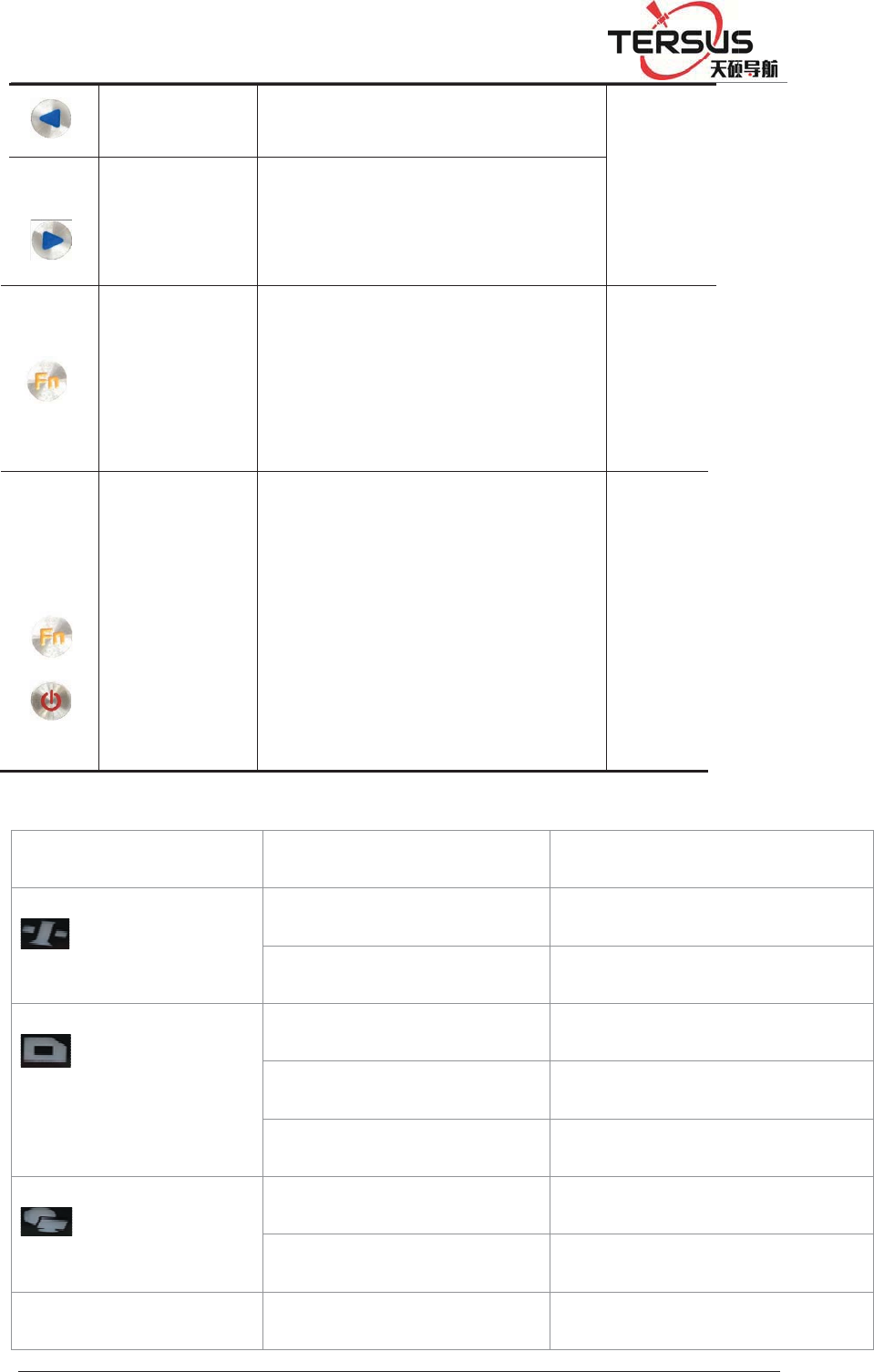
2.4 Button Function
Table 2.1 Button Description
Operation Description
Click button operation< 0.5 s
Double Click button operation interval <1 s
Long Press button operation>6 s
Table 2.2 Button Function Description
Button Name Function status
Power button
Double-click˖turns off / on the
LCD
See in
the LCD
Single click˖Boots, modify the
parameters and confirm
Long Press˖turn off
5RR
P
2.
5
LC
P
%XLOGLQJ
Le
f
Rig
h
F
u
B
Co
m
But
t
5
Indica
t
D inform
a
Satell
i
Recor
d
Netw
o
Po
w
/DQH=KDQ
J
f
t button
h
t button
u
nction
B
utton
m
bination
t
on
t
or light
s
a
tion
i
te ligh
t
d
ligh
t
o
rk ligh
t
w
er
/
J
KHQJ5RDG3X
G
Single
c
Single
down
Cancel
s
Press
t
the p
o
s
Status
Alway
s
Alway
s
Quick
f
Slow f
l
Alway
s
Alway
s
Alway
s
/
Quick
f
G
RQJ'LVWULFW6K
D
c
lick˖M
o
click ˖
M
s
or interf
a
t
he Fn bu
t
o
wer butto
the ke
r
s
brigh
t
s
off
f
lashing
l
ashing
s
off
s
brigh
t
s
off
f
lashing r
e
D
QJKDL
o
ve left or
M
ove rig
h
a
ce switc
h
t
ton and c
l
n To upg
r
r
nel;
ed
up
h
t or
h
S
L
l
ick
r
ade
T
sa
t
l
i
fl
a
Functio
n
Satellit
e
Satellit
e
Record
Recordi
Recordi
Connec
t
No net
w
Alarm
ee in
the
L
CD
T
he
t
ellite
i
ghts
are
a
shing
n
e
tracked
e
untracki
n
interval <
ng interv
a
ng stops
t
ed
w
ork conn
e
n
g
1 secon
d
a
l1 s
e
ction
5RR
P
Al
a
2.
6
St
a
Ne
t
1.
S
LC
D
Ala
r
Wi
-
P
%XLOGLQJ
a
rm Ligh
t
N
d
6
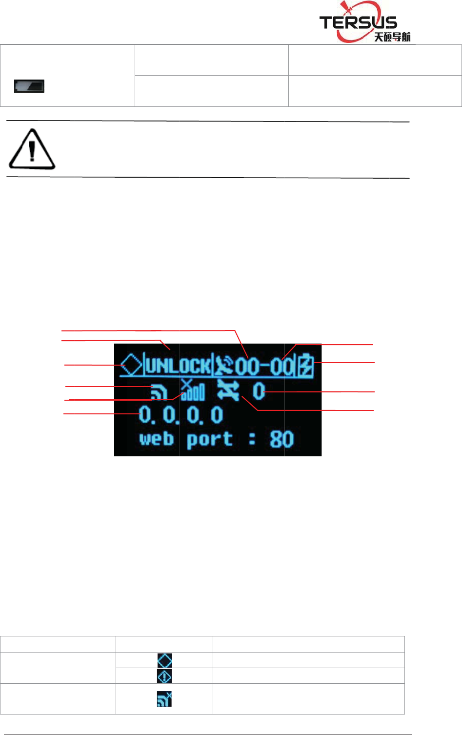
LCD
a
tus displ
a
t
work co
n
S
tatus Dis
p
1-Co
m
Status
7-Tot
a
Signa
l
D
status
r
m status
-
Fi status
1
2
3
4
5
6
/DQH=KDQ
J
N
otice:
d
d
isplay, t
h
a
y norma
l
n
nection s
t
p
la
y
Figu
r
m
mon sa
t
;4 - Wi-
F
a
l satellit
e
l
strength;
J
KHQJ5RDG3X
G
Alway
s
Alway
s
d
ouble-cli
c
h
e lights
w
l
ly will s
h
t
atus.
r
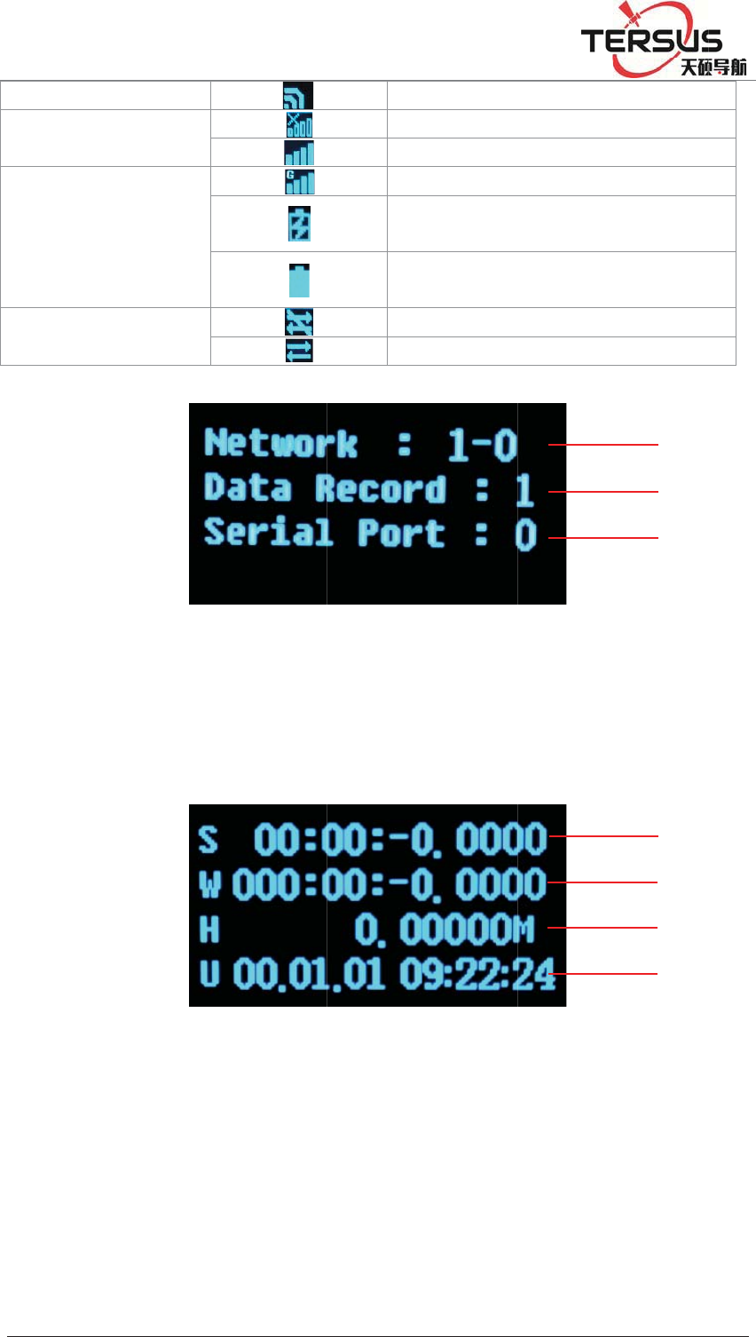
e 2-5 Ma
i
t
ellite N
u
F
i Status
e
number
10-3G N
e
Shows
G
RQJ'LVWULFW6K
D
s
yellow
s
green
c
k the p
o
w
ill turn o
f
h
ow the
S
i
n param
e
u
mbe
r
; 2
-
; 5-3G
N
;8-Powe
r
e
twork tra
n
me
No
Al
a
Wi
D
QJKDL
o
wer but
t
f
f except
fo
S
tatus of
e
ter infor
m
-
satellite
N
etwork
r
supply
/
n
smissio
n
aning
rmal status
a
rm
-Fi is off
Externa
l
Battery
t
on to o
p
fo
r the net
w
satellites,
m
ation
Lock S
t
Status; 6
/
battery
n
status;
l
power s
u
powered
p
en the
L
w
ork ligh
t
IP, port
t
atus;3-Al
-IP Add
r
powe
r
; 9
7
8
9
10
u
pply
L
CD
t
.
and
arm
r
ess;
-3G
5RR
P
3G
3G
Po
w
3G
tra
n
1-
1
L
P
%XLOGLQJ
network st
a
network st
a
w
er supply
network
n
smission s
t
Total ne
t
record st
r
L
atitude -;
2
/DQH=KDQ
J
a
tus
a
tus
t
atus
F
t
work str
e
r
eam; 3-
E
Fi
g
2
- Longit
u
J
KHQJ5RDG3X
G
F
igure 2-
6
e
am– En
a
E
nabled se
r
g
ure 2-7
C
u
de;3-Ele
v
G
RQJ'LVWULFW6K
D
Wi
Th
e
Th
e
Co
n
Ex
t
Ba
t
No
Da
t
6
Data tra
n
a
bled net
w
r
ial port
n
C
oordinat
e
v
ation;4-
U
D
QJKDL
-Fi is on
e
3G modu
l
e
3G modu
l
n
nected to
a
t
ernal pow
e
t
tery powe
r
data trans
m
t
a transmis
s
n
sfer stat
u
w
ork str
e
n
umbe
r
e
informa
t
U
TC time
l
e is off
l
e is on
a
public ne
t
e
r supply
r
e
d
m
ission
s
ion
u
s
e
am; 2-
E
t
ion
t
wor
k
E
nabled
d
1
3
2
1
2
3
4
d
ata
5RR
P
1-
S
nu
m
sk
y
1-
R
2.
D
P
%XLOGLQJ
S
atellite
n
m
ber of
G
y
R
eceiver
S
D
isplay s
e
5
/DQH=KDQ
J
F
n
umber
o
G
LONAS
S
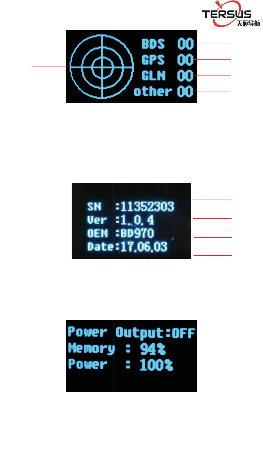
Figu
r
S
N numbe
r
F
e
tting
J
KHQJ5RDG3X
G
F
igure 2-8
o
f BDS;2
-
S
;4- Satell
i
r
e 2-9 Re
c
r
;2-Versi
o
F
igure 2-1
G
RQJ'LVWULFW6K
D
Satellite
i
-
Satellit
e
i
te numb
e
c
eiver sta
t
o
n;3-Mot
h
0 Status i
n
D
QJKDL
i
nformati
o
e
numbe
r
e
r of other
t
us infor
m
h
erboard
v
n
formati
o
o
n
r
of GP
S
;5- Satell
i
m
ation
v
ersion;4-
E
o
n
S
;3- Sate
i
te map o
f
E
xpire da
t
1
2
3
4
4
1
2
3
llite
f
the
t
a;
5RR
P
1-
D
1-
mo
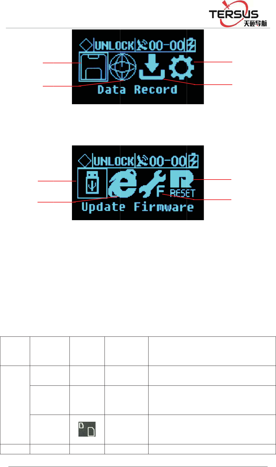
2.
7
Pan
e
Fro
n
Pan
e
Bac
k
P
%XLOGLQJ
D
ata reco
r
Firmwar
e
therboar
d
7
Extern
e
l Pan
e
Na
m
n
t
e
l
Mini
U
po
r
USB
p
TF
/
SIM
C
slo
t
k
GN
S
1
2
1
2
/DQH=KDQ
J
rd
;2- Net
w
e
Upgrad
e
d
;
al port
Ta
b
e
l
m
e
Pa
n
inst
r
o
n
U
SB
r
t
/
p
ort
/
/
C
ard
t
S
S G
N
J
KHQJ5RDG3X
G
Figure
w
ork setti
n
Figure 2
-
e
;2- Rest
o
b
le 2.5 Ex
t
n
el
r
ucti-
n
s
P
h
/
M
i
/
U
T
F
C
a
N
SS
T
G
RQJ'LVWULFW6K
D
2-11 Set
u
n
gs;3- Da
t
-
12 Syste
m
o
re the
d
t
ernal po
r
h
ysical
port
i
niUSB
U
SB-A
D
f
r
F
/SIM
a
rd slot
T
c
c
T
NC
C
D
QJKDL
u
p menu
t
a downlo
m
settings
d
efault IP
r
t descript
i
D
ata storag
e
f
irmware ,a
v
r
emovable
s
T
F card: st
o
c
ard: 3G /
2
c
ommunica
t
C
onnect th
e
a
d
;4- Sys
t
;3- reset;
i
ons
Functi
o
/
e
/ downlo
a
v
ailable fo
r
s
torage
o
rage data a
n
2
G wireless
t
ion;
e
GNSS ant
e
t
em settin
4- Reset
o
n
a
d, upgrade
r
U disk an
d
n
d ROM;
S
network
e
nna
4
3
4
3
gs;
the
d
USB
S
IM

5RRP%XLOGLQJ/DQH=KDQJKHQJ5RDG3XGRQJ'LVWULFW6KDQJKDL
Panel antenna ANT
External
clock
input
OSC TNC Connect with external atomic clock
3G
antenna 3G ANT SMA Connect the 3G / GPRS antenna
PPS
output PPS SMA PPS seconds pulse output
DB9
Serial port COM1 DB9
GNSS data output and external sensor
access port
LAN port LAN RJ45 Wired access to local area networks,
support 10M/100M
External
extension
EXT
Port
Fourteen
core port
˄LEMO˅
RS485: GNSS data output and external
sensor access;
RS232: debug serial port;
EX12: 12VDC output;
PW_RST: hardware reboot;
EVT: external event input (reserved);
power
input PW1
Two core
port
˄LEMO˅
Main power supply input;
Five-
core
socket
PW2
COM2
Small five
core port
˄LEMO˅
Auxiliary power supply input;
Differential data output;
Ground
point GND /
Grounding lightning protection
interface

5RRP%XLOGLQJ/DQH=KDQJKHQJ5RDG3XGRQJ'LVWULFW6KDQJKDL
Chapter3WEBAdministration
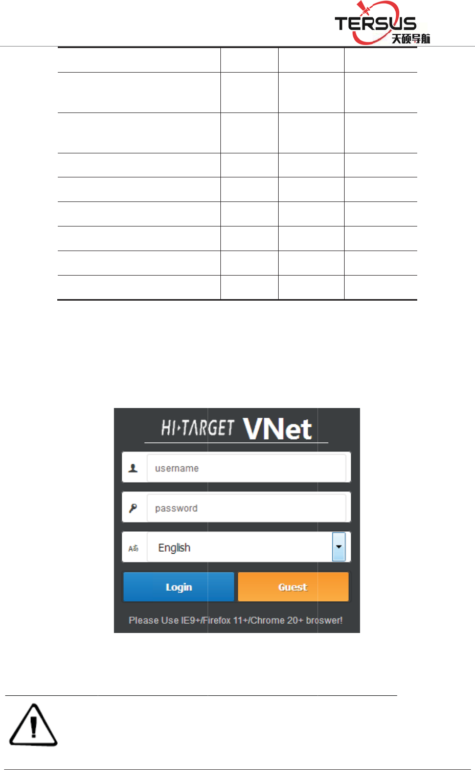
3.1 User login
After network setting, GNSS receiver can be remote access in LAN or WWW
through the IP Address.
For the convenience of management, all users are categorized into three groups.
A. Guest: users can log in without the enter of ID and password. They are
authorized to basic status check only.
B. Normal users: Must provide ID and password to log in, being authorized to
check system status, change parameters, browse, download, and delete data file.
Users are prioritized while the amount of online users reach the maximum
supported.
C. Administrator: Must log in with ID and password. Holding the highest level
of authority and able to add, delete accounts and change password of other users.
It is prioritized while the amount of online users reach the maximum supported.
Table 3.1 authority class with different user groups
Authority Guest Normal
user
Administrat
or
Check status
Check position info and
satellite status
Check logging file
Check data transmission status
Modify configuration ×
Set coordinate system and
observation parameters ×
5RRP
When
would
%XLOGLQJ/DQH
Contro
l
Downl
o
observ
a
Modif
y
config
u
Modif
y
Add or
Disco
n
Restar
t
Restar
t
Upgra
d
accessin
g
show as
t
Note
˖
=KDQJKHQ
J
l
and modi
f
o
ad or dele
t
a
tion file
y
data outp
u
u
ration
y
passwor
d
delete acc
o
n
nect other
u
t
the syste
m
t
the device
d
ing OS an
d
g
the W
E
t
he figure
F
WEB ad
m
phone, etc
system.
J
5RDG3XGRQJ
f
y log files
t
e
u
t
o
unt
u
se
r
m
d
Apps
E
B admi
n
3-1 belo
w
F
igure 3
-
m
inistration
o
. Please us
e
'LVWULFW6KDQJK
D
×
×
×
×
×
×
×
×
×
n
istration
w
.
-
1. Logi
n
o
f MatrixR
T
e
IE 9+/Fir
e
D
L
×
×
×
×
×
page of
M
n
interfa
c
T
K series s
u
e
fox 11+/C
h
M
atrixR
T
c
e
u
pport PC,
h
rome 20+
t
TK
a logi
server, tabl
e
t
o access th
e
n page
e
t, smart
e
WEB
5RRP%XLOGLQJ/DQH=KDQJKHQJ5RDG3XGRQJ'LVWULFW6KDQJKDL
Input ID and password and clickǏlog inǐto enter the WEB system. Or just click
ǏGuestǐto log in as guest with elementary authority.
After initialization, the system creates an administrator account automatically
with username ‘tersusgnss’ and password ‘tersusgnss’ (exclude quotation marks).
Normal user accounts could be created by administrator for the benefit of user
management with different authority level.
Note
˖
only one administrator account is allowed and password can be changed. If
you forget the password, please contact with Tersus for administrator
account or contact with administrator for normal usersÿ password reset.
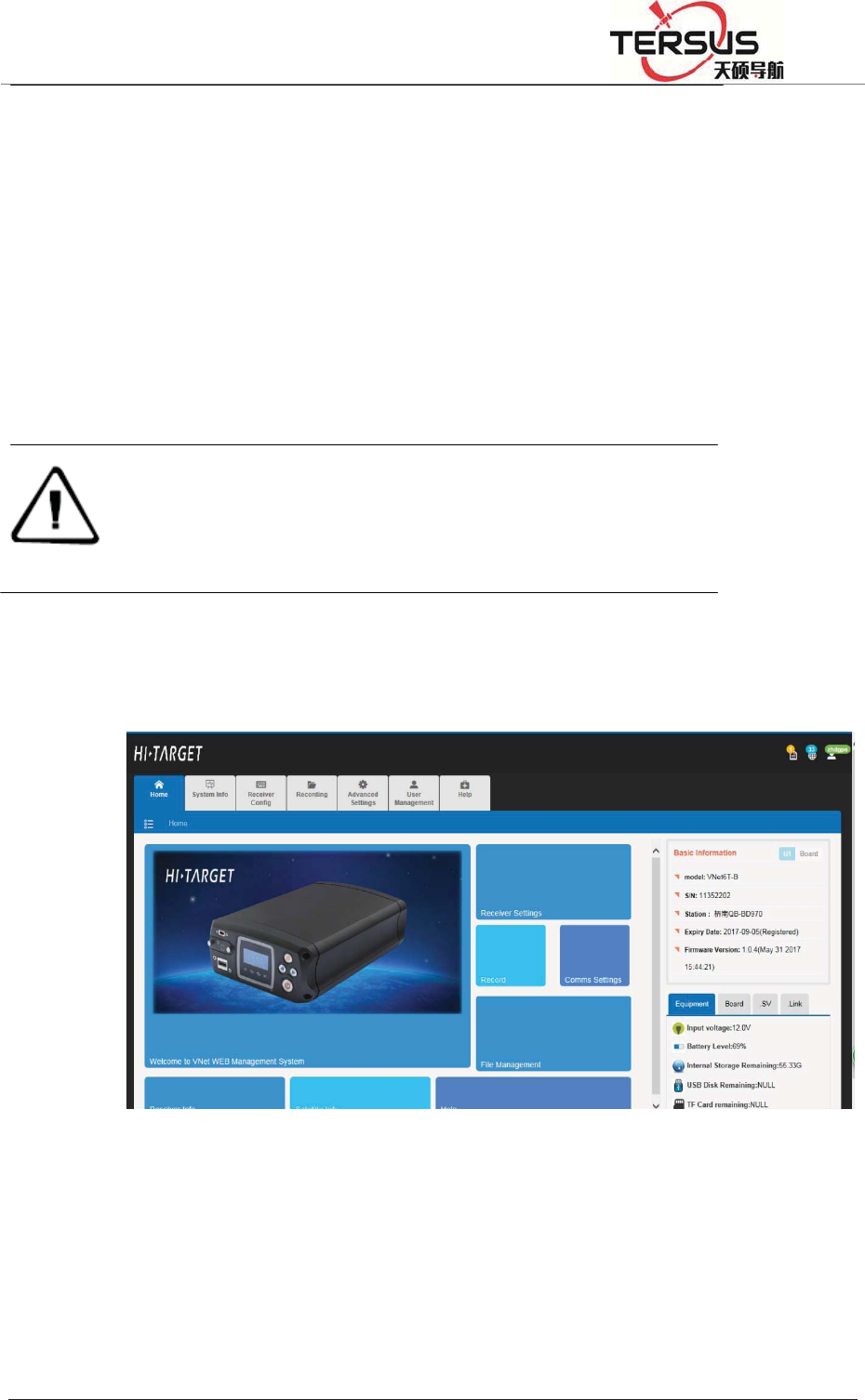
3.2 WEB interface for administration
Web interface including Home page, System info, Receiver settings, Record and
File management etc. Detail information see below pictures.
Figure 3-2. WEB interface
3.3 Elementary info
This sector located on the right hand part of WEB interface with the display of
instrument ID of receiver, firmware version, registration, instrument status,
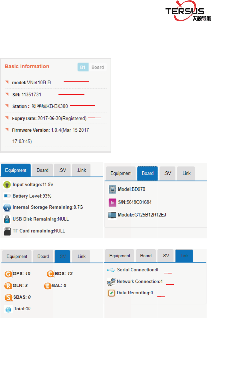
5RRP
mothe
r
etc.
%XLOGLQJ/DQH
r
board in
f
=KDQJKHQ
J
f
o, amou
n
J
5RDG3XGRQJ
n
t of obs
e
Figure 3-
3
Rece
i
SN, dis
p
C
u
'LVWULFW6KDQJK
D
e
rving sa
t
3
Basic i
n
i
ver model
w
p
lay in red
u
rrent statio
n
Registratio
D
L
ellite, co
m
n
formatio
n
w
ith suffix.
when regis
t
n
, revisabl
e
n status an
d
m
municat
i
n
t
ration cod
e
e
in Advanc
e
d
valid tim
e
Nu
m
N
u
Numb
e
i
on of re
c
e
expires.
e
d setting/
S
e
m
ber of ope
u
mber of ru
n
e
r of enabl
e
c
eivers,
S
ystem sett
i
ned port.
n
ning trans
m
e
d records.
i
ng
m
ission
5RRP
Statu
Satelli
t
to fig
u
Satelli
t
show
t
Curre
n
Langu
a
3.4 H
This i
n
data r
e
view,
h
directl
y
%XLOGLQJ/DQH
Note
˖
s bar
t
e status,
l
u
re 3-4).
t
e status:
t
he satelli
t
n
t account
a
ge settin
g
ome pa
g
n
terface i
s
e
cording,
o
h
yperlink
y
reach t
h
=KDQJKHQ
J
system lim
i
GNSS rec
e
contact wi
t
l
ogin acc
o
this icon
t
e info pa
g
: this ico
n
g
: change
g
e
s
compri
s
o
nline tra
n
option. B
y
h
e corresp
o
J
5RDG3XGRQJ
i
ts the displa
y
e
iver and exp
t
h Tersus for
o
unt and l
a
Figu
r
shows t
h
g
e.
n
shows c
u
language
s
ed of we
n
smissio
n
y
clickin
g
o
nding pa
g
'LVWULFW6KDQJK
D
y
of satellite
a
ired registrat
new code be
a
nguage s
r
e 3-4 Sta
t
h
e amoun
t
u
rrent log
i
between
E
lcome pa
n
, files do
w
g
the icon
i
g
e for fur
t
D
L
a
mount and
d
ion code. To
fore it expire
e
tting are
t
us ba
r
t
of obse
r
i
n inform
a
E
nglish a
n
ge, refer
e
w
nloadin
g
i
n hyperli
n
t
her oper
a
d
ata transmis
s
prevent this
i
s.
shown in
r
ving sat
e
a
tion.
n
d other l
a
e
nce stati
o
g
, instrum
e
n
k option
a
tion.
sion for unre
g
inconvenien
c
this sect
o
e
llites, cli
c
a
nguage.
o
n config
u
e
nt info,
s
sector, u
s
g
istered
c
e, please
o
r (refer
c
k it to
u
ration,
s
atellite
s
ers can

5RRP
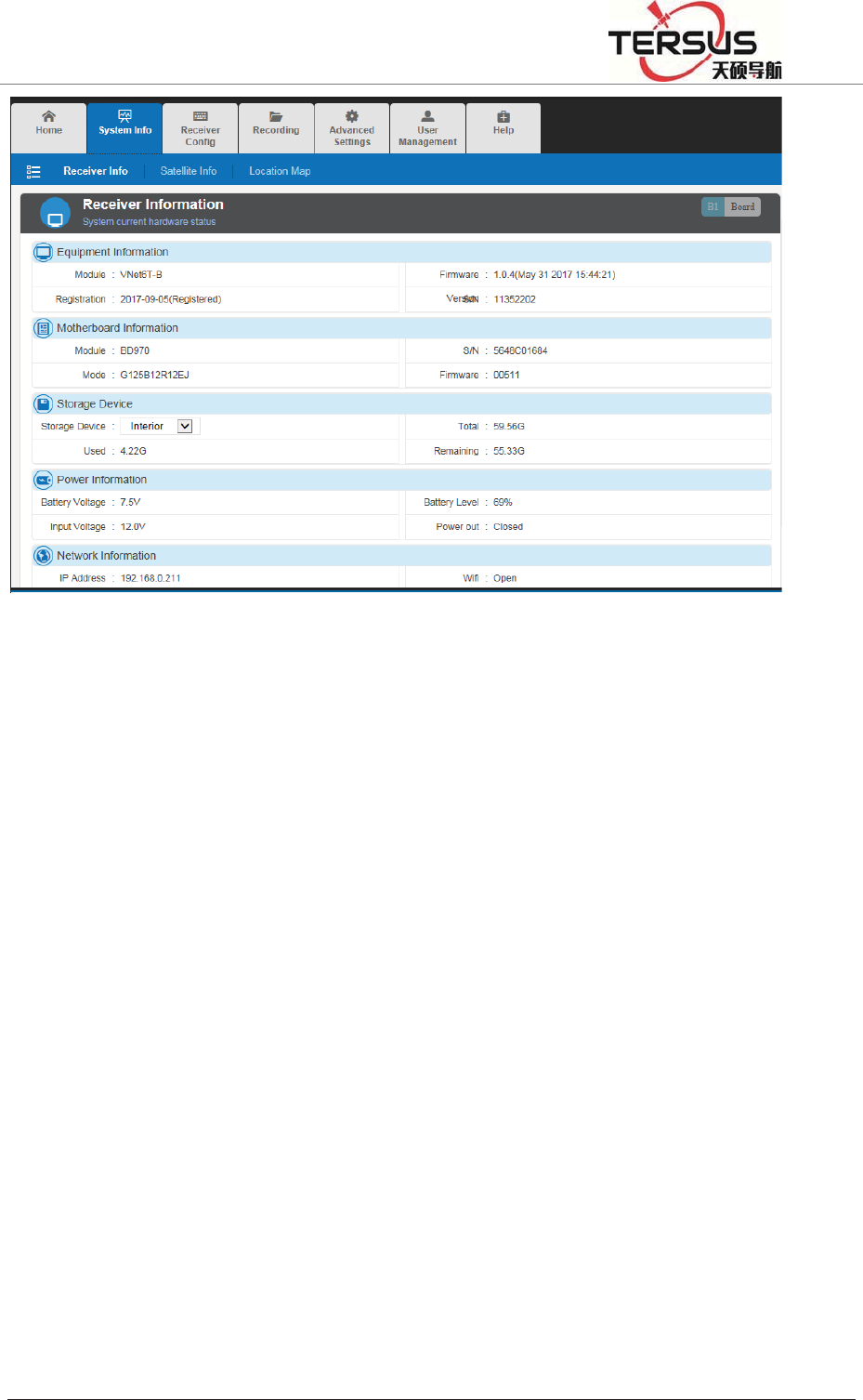
3.5 S
y
This s
e
info f
o
Displa
storag
e
%XLOGLQJ/DQH
y
stem in
e
ctor con
t
o
r the mor
e
ying curr
e
e
device,
p
=KDQJKHQ
J
fo
t
ains thre
e
e
detailed
e
nt status
p
ower su
p
J
5RDG3XGRQJ
Figur
e
e
module
s
display o
of syste
m
p
ply, netw
o
'LVWULFW6KDQJK
D
e
3-5. Ma
i
s
: instru
m
f GNSS r
e
m
includin
g
o
rk info a
D
L
i
n page
m
ent info,
e
ceiver st
a
g
instrum
e
s
shown i
n
satelli
t
e i
a
tus and
o
e
nt info,
m
n
figure 3
-
nfo and
p
o
bservatio
n
m
otherboa
r
-
6.
p
osition
n
.
r
d info,
5RRP%XLOGLQJ/DQH=KDQJKHQJ5RDG3XGRQJ'LVWULFW6KDQJKDL
Figure 3-6. Equipment info
In the storage device tab, different storage address (internal storage, U-disk, TF
card) could be chosen by clicking the inverted triangle on the right of dialog.
When changing the storage address, storage information will be updated and
displayed automatically.
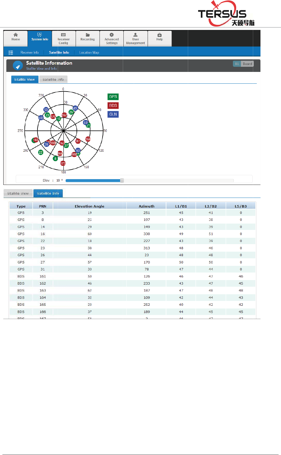
Satellite info
This sector shows the sky plot of satellites, satellite ID, altitude angle, azimuth,
signal-noise ratio (SNR), etc.
5RRP
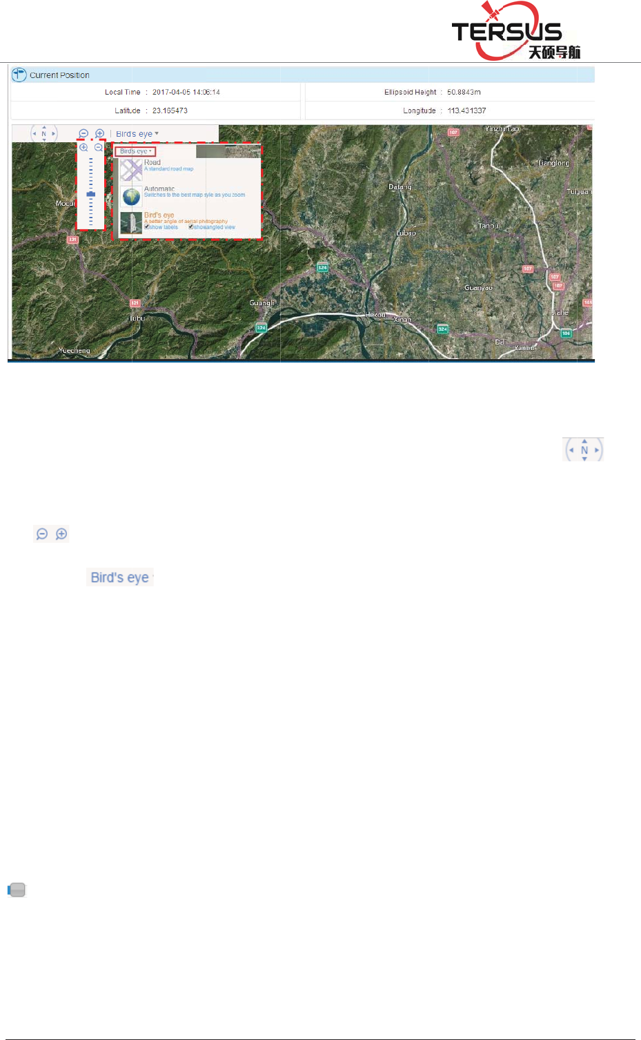
Positi
o
The e
x
(satell
i
%XLOGLQJ/DQH
o
n info
x
act locati
o
i
te image
a
=KDQJKHQ
J
o
n of dev
i
a
s default
J
5RDG3XGRQJ
figure
3
i
ce is sho
w
, refer to
f
'LVWULFW6KDQJK
D
3
-7. Satel
l
w
n in this
f
igure 3-8
)
D
L
l
ite info
sector an
d
)
.
d
display
e
e
d with b
a
a
se map
5RRP
Under
move
t
of
dialog
3.6 w
o
This s
e
as wel
l
Satell
i
Satelli
t
turn o
f
ca
n
increa
s
Ǐrese
%XLOGLQJ/DQH
the displ
a
t
he scree
n
. Besid
e
of
o
rking
m
e
ctor will
l
as onlin
e
i
te settin
g
t
e system
f
f . where
a
n
change
t
s
e). Click
i
t
ǐ. The i
=KDQJKHQ
J
a
y with b
a
n
with co
r
e
s, 2D dig
i
.
m
ode
introduce
e
transmis
g
switch o
n
a
s ǏON
ǐ
t
he value
i
ng ǏO
K
nterface
w
J
5RDG3XGRQJ
figure
3
a
se map,
p
r
respondi
n
i
tal map
a
configur
a
sion and
d
n
/off and
c
ǐ
indicate
of cu
t
-of
f
K
ǐto con
f
w
as show
n
'LVWULFW6KDQJK
D
3
-8. Posit
i
p
ress the
a
n
g directi
o
a
nd satelli
t
a
tion of s
a
d
ata recor
d
c
u
t
-off an
g
s workin
g
f
angle (d
e
f
irm para
m
n
as figur
e
D
L
i
on info
a
rrow ke
y
o
n. Zoom
t
e image
a
a
tellite, re
f
d
ing mod
u
g
le setting
g
status is
e
creasing
m
eter sett
i
e
3-9 belo
w
y
(on the i
in/out w
i
a
re availa
b
f
erence st
a
u
le.
: ǏOFF
ǐ
turn on.
D
with left
d
i
ng and r
e
w
.
con of
i
th pressi
n
b
le option
a
tion, seri
a
ǐ
means s
y
D
ragging t
h
d
rag and
r
e
set to de
f
) to
n
g icon
s in the
a
l ports
y
stem is
h
e icon
r
ight to
f
ault by
5RRP
Recei
v
This s
e
mode.
displa
y
catego
Anten
n
settin
g
Anten
n
%XLOGLQJ/DQH
v
er settin
g
e
ctor will
The loc
a
y
ed in pr
e
rized in
t
o
n
a model,
g
ÿ.
n
a decre
m
=KDQJKHQ
J
g
display t
h
a
l time, l
a
e
sent pos
antenna
s
fig
u
height a
n
m
ent˖th
e
J
5RDG3XGRQJ
figure 3
-
h
e positi
o
a
titude/lo
n
itioning
s
s
etting an
d
u
re 3-10.
R
n
d antenn
a
e
value c
o
'LVWULFW6KDQJK
D
-
9. Satelli
t
o
ning stat
u
n
gitude, e
l
s
tatus an
d
d
working
R
eference
a
decreme
n
o
uld be
s
D
L
t
e setting
u
s, antenn
l
evation,
H
d
referenc
mode set
t
station se
t
n
t could b
s
et in th
e
a parame
t
H
DOP, P
D
e station
t
ing.
t
ting
e configu
r
e
range
o
t
ers and
w
D
OP, VD
configur
a
r
ed in þ
A
o
f 5dB t
o
w
orking
OP are
a
tion is
A
ntenna
o
20dB

5RRP%XLOGLQJ/DQH=KDQJKHQJ5RDG3XGRQJ'LVWULFW6KDQJKDL
according to the motherboard model and antenna model. Here is the calculating
formula below:
Antenna decrement = antenna gain- motherboard gain- cable gain
Antenna model: in base station mode, choosing right antenna model to calibrate
the phase center position.
Antenna height: in base station mode, input the height to calibrate measured
elevation value.
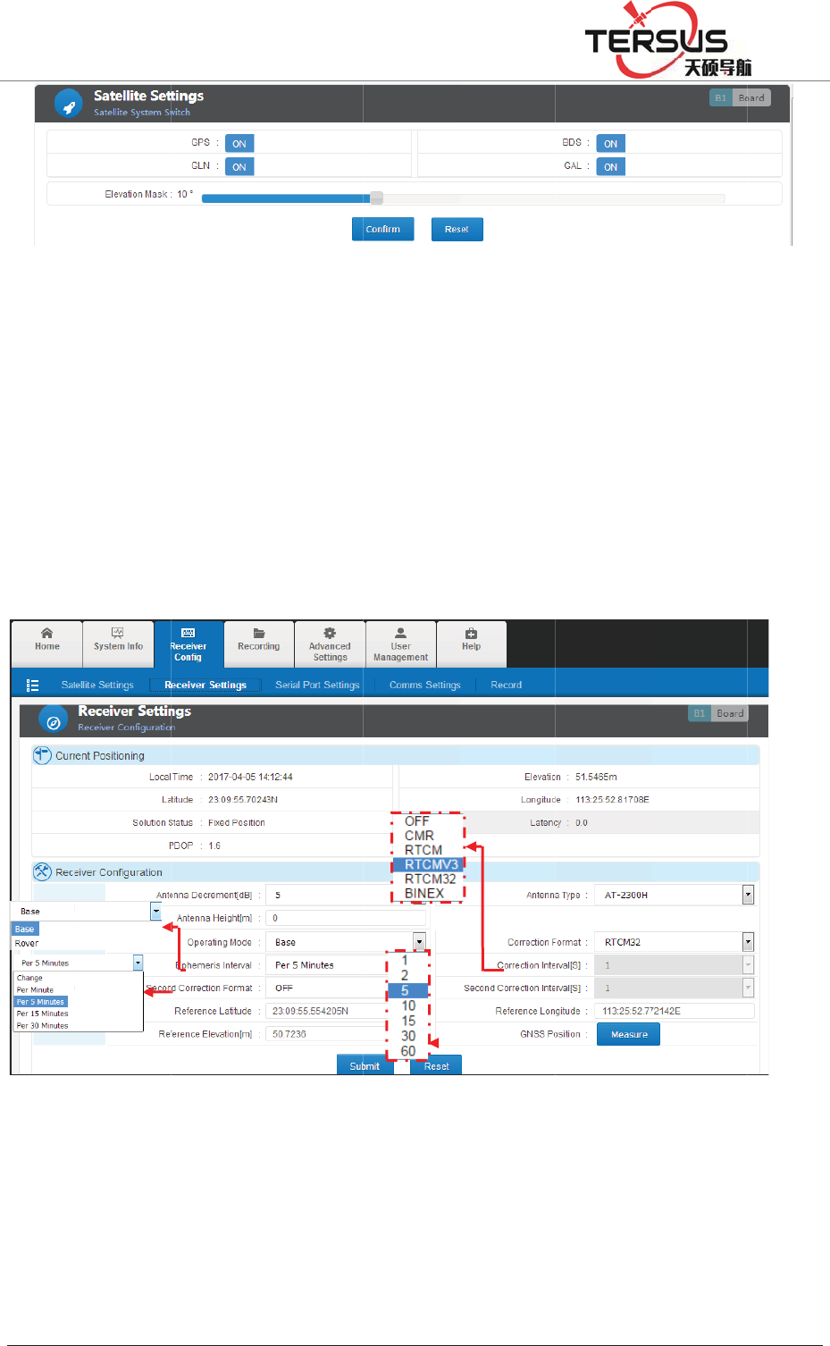
Receiver could be set as base station or rover station. other settings in terms of
data recording, GNSS data output via serial port, network transmitted data are
various as the different mode setting.
Table 3.2 reference station setting and data output
Working
mode
Second
correction Time tab Raw data option Correction option
Base
off off Output raw data Output correction
on off Output correction Output correction
off on Output raw data Output time tab
on on Output correction Output time tab
Rover - off Output raw data Output GGA data
- on Output raw data Output time tab
Base station
Base station setting contains correction data format, correction interval,
ephemeris output interval, 2nd correction output and station coordinates setting

5RRP
& aut
o
Ephe
m
Corre
c
output
˄RT
C
Coord
i
set as
d
Coord
i
the set
t
Rov
e
In rov
e
GGA
o
forma
t
correc
t
%XLOGLQJ/DQH
o
-acquire.
m
eris inter
v
c
tion data
˅ˈCM
C
M3.2˅.
i
nates inp
u
d
ecimals
w
i
nates aut
o
t
ing.
e
r Station
er
station
o
utpu
t
s
h
t
, epheme
r
t
ion mess
a
=KDQJKHQ
J
F
v
al˖setti
n
format/2
n
RˈRTC
M
u
t manua
l
w
ith no
m
o
-acquire:
working
h
ould be
s
r
is interv
a
a
ge chan
n
J
5RDG3XGRQJ
F
igure 3-1
n
g interv
a
n
d correct
i
M
(RTC
M
l
ly˖follo
w
m
ore than
8
average
m
mode, c
o
s
e
t
. Refe
r
a
l is the
s
n
el.
'LVWULFW6KDQJK
D
1 Base st
a
a
l as 1min
i
on outpu
t
M
2.3)ˈR
T
w
ing the
f
8
decimal
p
m
easure c
o
rrection
d
r
to the b
s
ame as t
h
D
L
a
tion setti
n
, 5mins, 1
t
˖setting
a
T
CMV3
˄
f
ormat D
D
p
laces.
oordinate
s
d
ata form
a
ase stati
o
h
e Base.
G
n
g
5mins or
a
s OFF˄
n
˄
RTCM3
.
D
:MM:SS
,
s
. Press
Ǐ
a
t, ephe
m
o
n setting
,
G
GA mes
s
30mins.
n
o correcti
.
0˅ˈR
T
,
second c
o
Ǐ
submitǐt
o
m
eris inter
v
,
correcti
o
s
ages out
p
on data
T
CM32
o
uld be
o
finish
v
al and
o
n data
p
uts by
5RRP
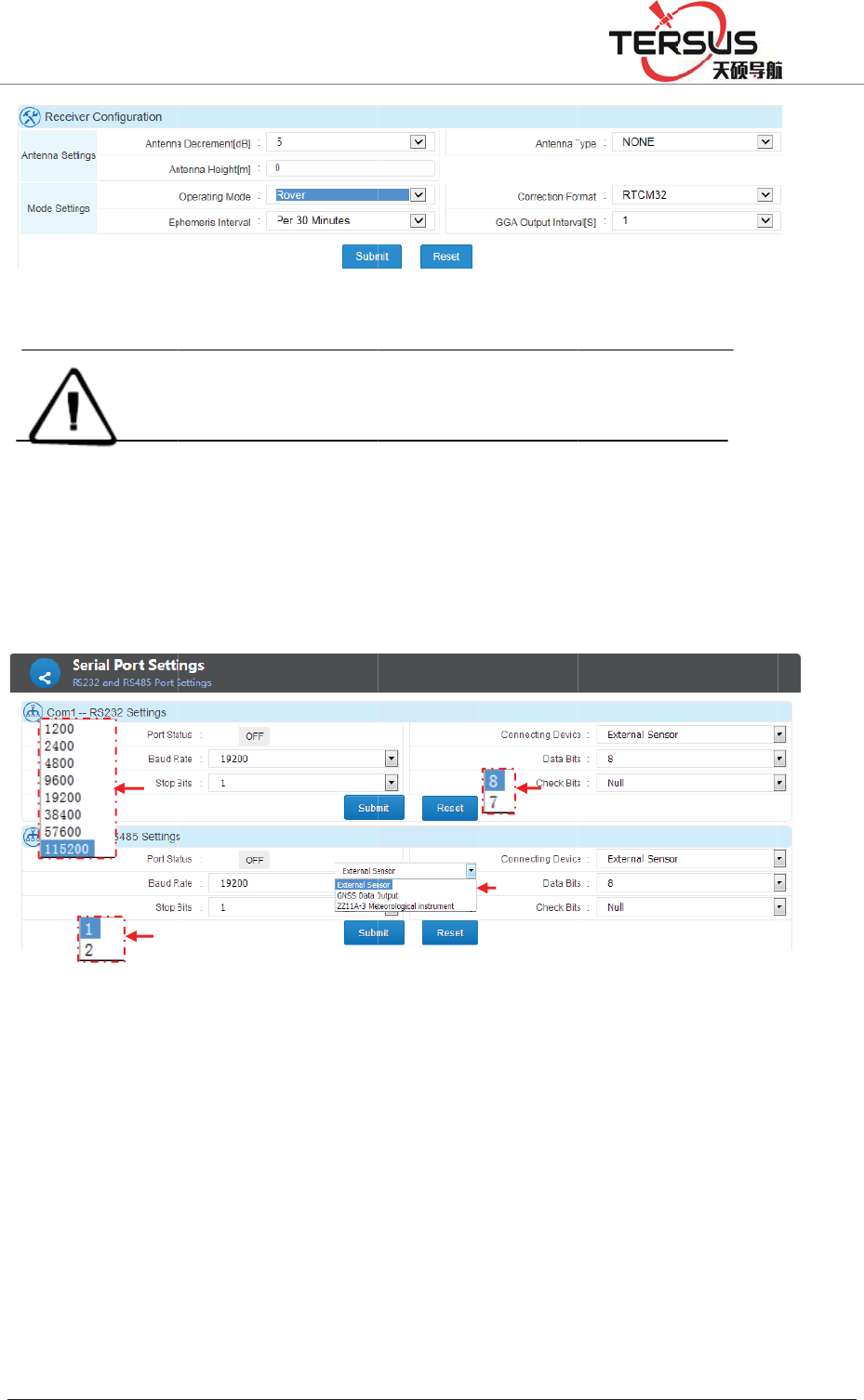
Serial
RS23
2
data o
u
Serial
p
The in
t
GNSS
Exter
n
conne
c
and c
h
%XLOGLQJ/DQH
Note
˖
port sett
i
2
and RS
4
u
tput and
p
ort Bau
d
t
roductio
n
data out
p
n
al senso
r
c
tingǐ, c
h
h
eck bits
a
=KDQJKHQ
J
1. On base
s
2. Raw dat
a
raw data di
s
i
n
g
4
85 port p
sensor d
a
d
rate, Dat
a
F
n
below f
o
p
ut.
r
: setting
h
oose Ǐ
e
a
ccording
J
5RDG3XGRQJ
Figure
3
s
tation mode
,
a
cannot be r
e
s
played on th
e
ossess id
e
a
ta input.
a
bits, sto
p
F
igure 3-1
o
llows set
t
Ǐserial
e
xternal s
e
to the e
q
'LVWULFW6KDQJK
D
3
-12 Rov
e
,
set correcti
o
e
corded and t
r
e
data trans
m
e
ntical fu
n
They two
p
bits, ch
e
3. Serial
p
t
ing RS23
port stat
u
e
nso
r
ǐ. T
h
q
uipment
p
D
L
e
r setting
o
n format as
R
r
ansmitted if
m
ission page
i
n
ction tha
t
share th
e
e
ck bits, e
t
p
ort setti
n
2 as sens
o
u
sǐ as
h
en set b
a
p
arameter
R
TCM if RT
D
turn on 2nd c
o
i
s virtually th
e
t
could b
e
e
same se
t
t
c.
n
g
o
r data in
p
ǏONǐ.
a
ud rate,
d
s and co
n
D
correction
i
o
rrection out
p
e 2nd correcti
e
used fo
r
t
ting met
h
p
ut and R
S
In Ǐeq
u
d
ata bits,s
t
n
firm by
c
i
s needed.
p
ut. The
on data.
r
GNSS
h
od e.g.
S
485 as
u
ipment
t
op bits
c
licking

5RRP%XLOGLQJ/DQH=KDQJKHQJ5RDG3XGRQJ'LVWULFW6KDQJKDL
Ǐsubmitǐ.
GNSS data output˖setting Ǐport statusǐ as ǏONǐˈIn Ǐconnecting deviceǐ,
set as Ǐexternal sensorǐ and choose corresponding Ǐdata typeǐˈset baud rate,
data bits, stop bits and check bits and confirm by clicking Ǐsubmitǐ.
Note
˖
1. Make sure set right baud rate, data bits, stop bits and check bits, otherwise, would
reveal wrong message.
2. ‘Correction data’ is in connection with reference station working mode. In base
station mode, the correction data is the correction received by receivers whereas
GGA data outputted from receivers in rover mode.
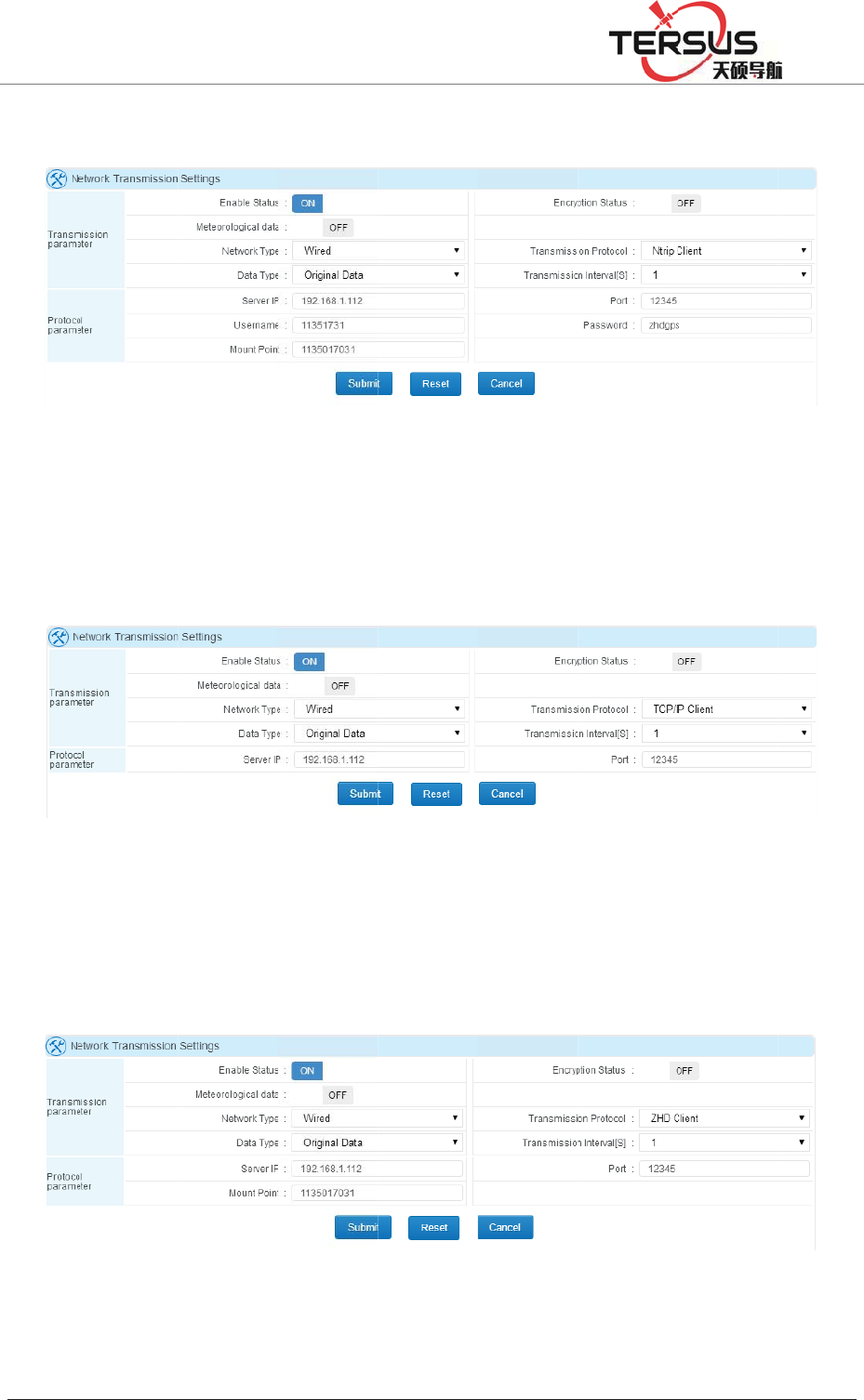
Comms transmission (Network transmission)
Transmission table consists of:
Serial number: the order code for online transmission.
Utilization: showing the status of chosen online transmission (on/off).
Status: this status contains ‘connecting’ and ‘connected’ two options.
‘connecting’ indicates this transmission is trying to connect or cannot connect.
While ‘connected’ means the transmission is connected.
Network type: consists of cable line, Wi-Fi, 2G/3G.
Protocol: the network protocol adopted, consists of Ntrip ClientǃTCP/IP Clientǃ
TRS ClientǃUDP ClientǃSG ClientǃNtrip ServerǃTCP/IP Server and UDP in
which Server TRS Client and SG Client are Tersus protocols.
IP address: displaying IP and port of receiver when set as server and displaying
server’s when set as client side.
Operation: contains switch on/off, editing and deleting transmission.

5RRP
Click
trans
m
3-14)
Ǐadd
i
Encry
p
proces
Relev
a
Netw
o
Data t
y
Raw d
2s, 5s,
There
Detail
Ntrip
%XLOGLQJ/DQH
b
utton
t
m
ission. T
h
shown
w
i
ng online
p
tion stat
u
sed using
a
nt definit
i
o
rk Type˖
y
pe: NM
E
ata outpu
t
10s, 15s,
are 8 pr
o
settings a
Client,
N
=KDQJKHQ
J
fi
g
t
o add a
o
h
e online
w
hen addi
n
transmis
s
u
s: when
Tersus s
o
i
ons inǏ
C
cable, W
i
E
A-0183,
t
could se
t
30s, 60s)
.
o
tocols av
a
s below s
h
N
trip Ser
v
J
5RDG3XGRQJ
g
ure 3-14
.
o
nline tra
n
transmis
n
g or ed
i
s
ionǐ in
this fun
c
o
ftware or
C
omms tr
a
i
-Fi, 2G/3
correcti
o
t
Ǐtrans
m
.
a
ilable w
i
h
ows.
v
er shar
e
'LVWULFW6KDQJK
D
.
Comms
t
n
smission.
sion con
f
i
ting the
t
chapter
Ǐ
c
tion is s
software
i
a
nsmissi
o
G are av
a
o
n data, r
a
m
ission i
n
i
th option
e
the sa
m
D
L
t
ransmiss
i
Click Ǐ
e
f
iguration
t
ransmiss
i
Ǐ
b
asic op
e
witched
o
i
ntegrate
d
o
n setting
ǐ
a
ilable.
a
w data,
n
tervalǐ
s of net
w
m
e settin
g
i
on
e
di
t
ǐto e
d
dialogue
i
on. Refe
r
e
rationǐ
o
n, the d
d
with Ter
s
ǐ
RS232 d
a
(0.05s, 0.
w
ork setti
n
g
, define
d
it curren
t
(refer t
o
r
to the
for more
ata can
b
s
us proto
c
a
ta, RS4
8
1s, 0.2s,
0
n
g and da
t
the par
a
t
online
o
figure
c
hapter
details.
b
e only
c
ol.
5 data.
0
.5s, 1s,
t
a type.
a
meters
5RRP
accor
d
TCP/I
P
(show
n
TRS
C
port a
n
%XLOGLQJ/DQH
d
ing to the
F
P
Clien
t
ǃ
n
as figur
e
F
C
lien
t
is
T
n
d Mount
=KDQJKHQ
J
local net
w
F
igure 3-
1
UDP Cli
e
3-16).
F
igure 3-1
T
ersus de
fi
Point (re
f
F
J
5RDG3XGRQJ
w
ork setti
n
1
5 Ntrip
C
ent share
6 TCP/IP
fi
ned tran
s
f
er to figu
r
F
igure 3-1
'LVWULFW6KDQJK
D
n
g (refer
t
C
lient and
the same
Client an
d
s
parent tr
a
r
e 3-17).
7 TRS Cl
D
L
t
o figure
3
Ntrip Ser
v
setting,
d
d
UDP Cl
a
nsport p
r
ien
t
setti
n
3
-15).
v
er settin
g
d
efine IP
ient setti
n
r
otocol, s
e
n
g
g
address a
n
n
g
e
tting IP
a
n
d port
a
ddress,
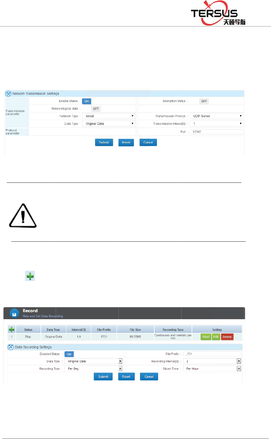
5RRP
TCP/I
P
server.
only r
e
Data l
Click
shown
%XLOGLQJ/DQH
P
Serve
r
ǃ
Under t
h
e
ceiver p
o
Notic
e
o
gg
in
g
to a
d
as blow.
=KDQJKHQ
J
UDP S
e
h
is config
u
o
rt setting
s
മ3-18
T
e
˖
1. For net
w
server IP a
n
2. Correcti
o
outputs cor
r
3. While t
r
connecting
d
d a new
d
J
5RDG3XGRQJ
e
rver tran
s
u
ration, I
P
s
are need
e
T
CP/IP S
e
w
ork transmi
s
n
d port.
o
n data outp
r
ection mess
a
r
ansmitting
d
‘External Se
n
d
ata recor
d
Figure
'LVWULFW6KDQJK
D
s
port pro
t
P
address i
e
d.
e
rver and
U
s
sion, differe
n
ut is related
a
ge whereas
G
d
ata via RS
2
n
sor’ as devi
c
d
, set up t
h
3-20 data
D
L
t
ocol are
s the one
U
DP Ser
v
n
t protocol c
a
to receiver
G
GA data w
o
2
32 or RS48
5
c
e.
h
e data ty
p
logging
applied
w
of receiv
e
v
er setting
a
nnot be set
c
working m
o
o
uld be outpu
5
port, turn
p
e, recor
d
w
ith recei
v
e
r address
c
onnecting t
o
o
de. In Base
u
t for Rover
m
on the port
d
ing inter
v
v
ers as
so that
o
the same
mode, it
m
ode.
first and
v
al ,etc.

5RRP
Enabl
e
heade
r
origin
a
differ
e
Recor
d
record
s
choos
e
data r
e
ǏSta
r
ǏDel
e
3.7 F
i
File
m
storin
g
access
i
File li
s
In thi
s
differ
e
%XLOGLQJ/DQH
e
the dat
a
r
, the def
a
a
l data an
d
e
nt record
i
d
ing meth
s
, etc., w
h
e
a file e
v
e
cord for
m
rt
ǐǏSto
p
e
teǐmea
n
i
le man
a
m
anageme
n
g
, checki
n
i
ble for N
s
t
s
functio
n
e
nt device
.
=KDQJKHQ
J
a
record a
n
a
ult settin
g
d
Rinex
f
i
ng interv
a
ods are r
e
h
en the d
a
v
ery day,
e
m
at as nee
d
p
ǐis for
t
n
s to eras
e
a
gement
n
t includi
n
n
g, down
l
ormal us
e
n
, users
c
.
Those fi
l
J
5RDG3XGRQJ
n
d then
s
g
is _zhd
)
f
ormats.
A
a
l.
e
corded e
v
a
ily recor
d
e
very ho
u
d
ed. After
t
he status
s
e
one ite
m
n
g File li
l
oading,
d
e
rs and A
d
c
an chec
k
l
es could
b
'LVWULFW6KDQJK
D
s
et the fl
a
)
, select t
h
A
t the sa
m
v
ery day,
m
d
mode i
s
u
r, every t
w
setting, c
s
witch of
m
from exi
s
st and F
T
d
eleting a
l
d
ministrat
o
k
and ma
n
b
e auto d
e
D
L
a
g name (
h
e record
m
e time d
a
m
anual re
s
enabled
w
o hours
lick the [
S
existing t
r
s
tence
T
P push f
u
l
l data fi
l
o
r.
n
age the
e
leted via
s
the file
n
data type
a
ta record
cording a
n
to record
split a fi
l
S
ubmit] b
u
r
ansmissi
o
u
nction.
U
l
es. This
recordin
g
s
etting ‘A
u
n
ame of
d
, we pro
v
s can be
s
n
d planni
n
the file c
l
e The Se
l
u
tton.
o
n.
U
sers are
function
g
files st
o
u
to clean
d
ata file
v
ide the
s
et to a
n
g time
an also
l
ect the
able to
is only
o
red in
time’.

5RRP%XLOGLQJ/DQH=KDQJKHQJ5RDG3XGRQJ'LVWULFW6KDQJKDL
Figure 3-21 File list
Stored directory could be selected internal (internal storage), U-disk and TF card.
Once the record date is chosen, the page will refresh automatically.
File name: the name of recorded data files.
Type: the data type of files, normally they are RINEX file or Original data
(RAW data) file.
Size: Disk storage space.
Start recording time: the beginning time of this recording, usually the moment
when file was created.
End recording time: the ending time of this recording, that is the moment when
this recording stop.
Operation: To download or delete this data record.
The downloading function of file list could be conducted by ordinary download
or FTP download. Refer to chapter ‘data downloading’ in ‘basic operation’.
There are three ways to go for data deleting action.
Simple delete: only for deleting single file, directly clicking ǏDeleteǐbutton on
the recording form.
Selective delete: when delete more than one file, select by ticking them on the
row head then click ǏDelete selectedǐ. All items could be selected by tick the
header tick box.
5RRP
Forma
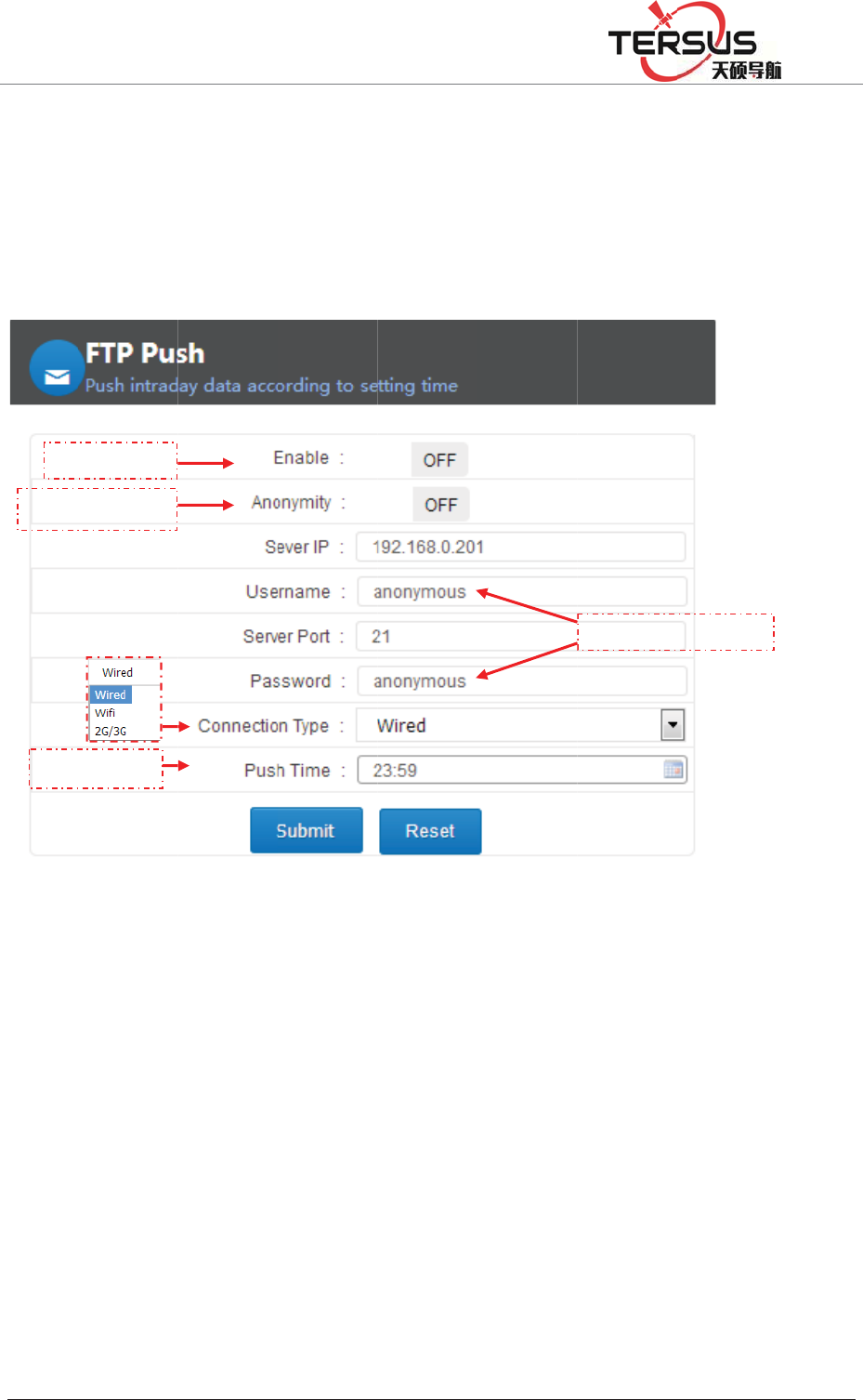
FTP p
FTP p
u
time p
o
ǏRes
e
apply
t
3.8 A
d
The A
d
includ
i
mana
g
Adva
n
view.
F
Anony
m
Time
%XLOGLQJ/DQH
t: deletin
g
ush
u
sh funct
i
o
int to th
e
et
ǐ
b
utto
n
t
he settin
g
d
vance
d
d
vanced
p
i
ng host
g
ement vi
e
n
ced page
s
F
TPSwitch
m
itySwitch
setting
=KDQJKHQ
J
g
all data
f
i
on coul
d
e
server.
D
n
would r
e
g
.
d
setting
p
age prov
i
settings,
e
wing.
s
are onl
y
J
5RDG3XGRQJ
f
ile.
d
send the
D
etailed c
o
Figur
e
e
set the s
e
i
des adva
n
mother
b
y
open to
'LVWULFW6KDQJK
D
data file
o
nfigurati
o
e
3-22 FT
P
e
tting as f
a
n
ced com
m
b
oard set
t
administ
r
D
L
recorded
o
n displa
y
P
push
a
ctory de
f
m
ands an
d
t
ings, ne
r
ators and
between
y
ed below
:
f
ault, clic
k
d
operatio
n
twork s
e
others a
r
Username
/
00:00 an
:
k
ǏSub
m
n
s for the
e
ttings, a
n
r
e not all
o
Password
d fixed
m
i
t
ǐ to
device,
n
d log
o
wed to
5RRP
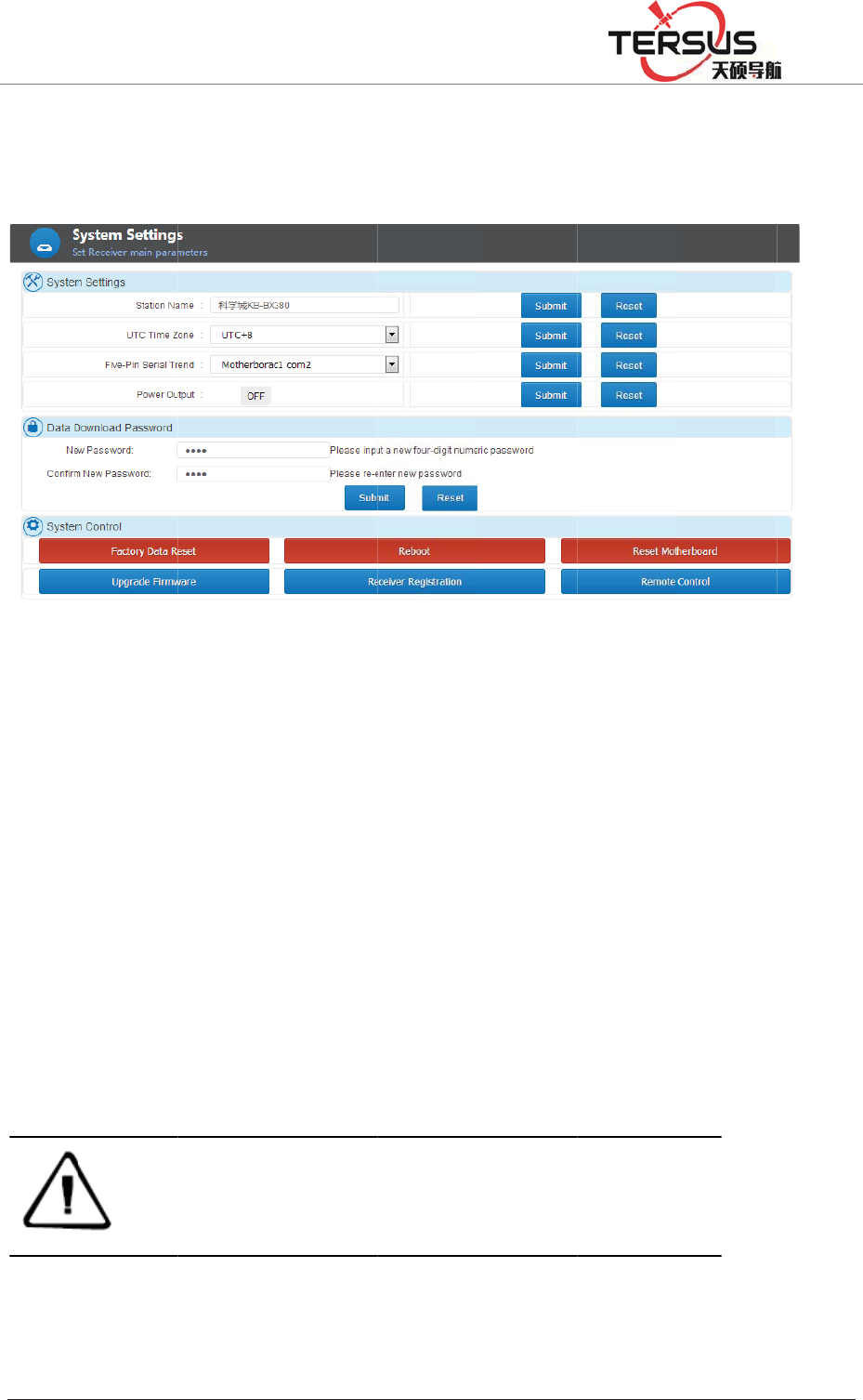
S
y
ste
m
Syste
m
syste
m
1. S
y
s
t
a. Stat
i
chang
e
b
. UT
C
the d
e
Ǐsub
m
c. Fiv
e
mothe
r
limite
d
the po
r
d. Po
w
%XLOGLQJ/DQH
m
Settin
gs
m
settings
m
control.
t
em setti
n
i
on name
e
it, just d
i
C
time zo
n
e
fault val
u
m
itǐ.
e
-pin seri
a
r
board.
T
d
from se
n
r
t and clic
Note
˖
w
er output
=KDQJKHQ
J
s
is comp
o
ng
s
settings:
s
i
rectly in
p
n
e: from
t
u
e is U
T
a
l Tren
d
: t
h
T
hat mak
e
n
ding co
m
k Ǐsub
m
COM1 is u
s
tag are outp
u
through it.
: This fun
c
J
5RDG3XGRQJ
o
sed of s
y
Figure 3
-
s
et the sta
t
p
ut the na
m
t
here are
2
T
C +8; t
o
h
is five-p
i
e
s it pos
s
m
mand or
m
i
t
ǐ.
s
ed for data
o
u
t via COM2.
c
tion cou
l
'LVWULFW6KDQJK
D
y
stem set
t
-
23 syste
m
t
ion name
m
e and th
e
2
5 zones i
o
change
i
n serial p
o
s
ible to
o
message
t
o
utput e.g. G
G
As for CO
M
l
d supply
p
D
L
t
ings, dat
a
m
settings
, the defa
u
e
n click
n total fr
o
it, select
o
rt has be
o
btain da
t
t
o mother
b
G
A, GSV, et
c
M
3, raw data/
p
ower wi
t
a
downlo
a
u
lt value i
Ǐsubmitǐ
o
m UTC -
the rig
h
en directl
y
t
a from
m
b
oar
d
. To
c
whereas co
r
second corre
t
h 12VD
C
a
d passw
o
s "Statio
n
button.
12 to UT
C
ht
one an
d
y
connect
e
m
otherbo
a
change i
t
r
rection mess
e
ction messa
g
C
ˈ5W de
v
o
rd and
n
A". To
C
+ 12,
d
click
e
d with
a
rd but
t
, select
age/ time
g
e output
v
ices.
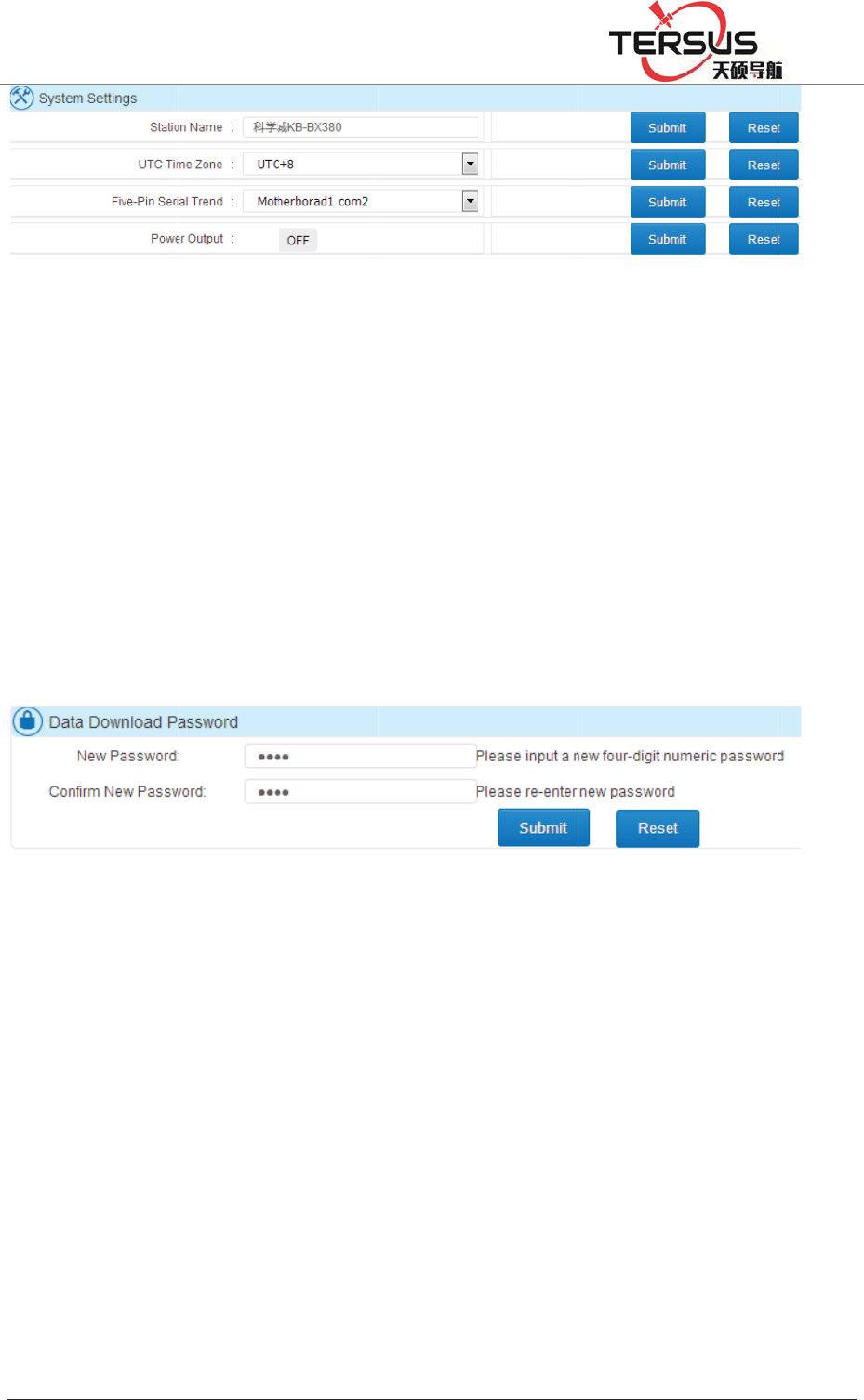
5RRP
2. Dat
a
The p
a
data fi
l
four d
i
click
reset b
3. S
y
s
t
Users
restor
e
receiv
e
Resto
r
pop u
p
restart
Anne
x
%XLOGLQJ/DQH
a
downlo
a
ssword i
s
l
e downl
o
i
gits with
Ǐsubmit
ǐ
ack to 12
3
t
em cont
r
can rem
o
e
factory
s
e
r registr
a
r
e factory
s
p
, click
Ǐ
automati
x
[restore
f
=KDQJKHQ
J
ad passw
s
designe
d
o
ading wi
t
default s
e
ǐ
. Clicki
n
3
4.
Fig
u
r
ol
o
tely con
t
s
ettings, r
e
a
tion and
r
s
ettings:
C
Ǐ
OKǐ;
T
cally. Af
t
f
actory se
t
J
5RDG3XGRQJ
Figure 3
-
ord
d
for sec
u
t
hin the u
s
e
tting 12
3
n
g ǏRes
e
u
re 3-25
D
t
rol the r
e
e
start, an
d
r
emote co
n
C
lick Ǐ
R
T
he receiv
e
t
er the re
s
t
tings];
'LVWULFW6KDQJK
D
-
24 Syste
m
u
rity of lo
c
s
e of LE
D
3
4; to cha
et
ǐ and
D
ata dow
n
e
ceiver v
i
d
reset th
e
n
trol.
R
estore Fa
c
e
r will re
t
s
tart to d
e
D
L
m
settings
c
al data
d
D
button.
T
n
ge it, e
n
Ǐsubmit
load pass
w
i
a this w
e
e
motherb
o
c
tory Sett
i
t
urn to th
e
e
lete all
t
d
ownloadi
n
T
his strin
g
n
ter the n
e
ǐ, the pa
w
or
d
e
b page.
o
ard, upg
r
i
ngsǐ, th
e
factory
d
t
he data
a
n
g. Appl
y
g
is comp
o
e
w passw
o
ssword w
o
Mainly i
n
r
ading fir
m
e dialog
b
d
efault va
l
a
nd setti
n
y
ing for
o
sed of
o
rd and
o
uld be
n
clude:
m
ware,
b
ox will
l
ue and
n
gs, see
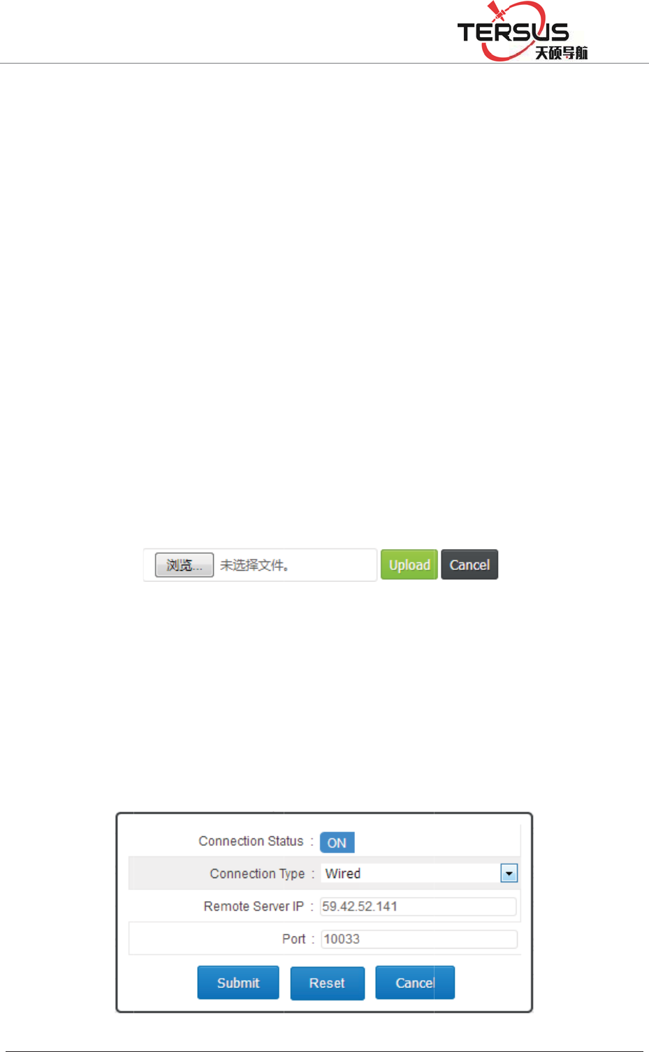
5RRP
b
. Re
b
The r
e
minut
e
c. Res
e
[reset
m
record
d. Up
g
name
"
expan
d
ǏUpl
o
e. Rec
e
Opera
t
f. Re
m
b
elow.
%XLOGLQJ/DQH
b
oot: Rec
e
e
ceiver
w
e
.
e
t the mo
t
m
otherbo
a
re-create
s
g
rade the
f
"
Tersus_
U
d
the fol
l
o
a
d
ǐ. F
o
e
iver regi
s
t
ion See
m
ote cont
r
=KDQJKHQ
J
e
iver rest
a
w
ill restar
t
t
herboard
:
a
rd], and
p
s
the log
f
f
irmware:
U
pdate.bi
n
l
owing i
n
o
r details,
s
Fig
u
s
tration: I
n
ǏBasic
O
r
ol: Click
J
5RDG3XGRQJ
a
rt, click
Ǐ
t
within
1
:
GNSS b
p
op-up d
i
f
ile.
Upgrade
n
", cannot
n
terface,
c
s
ee ǏBa
s
u
re 3-26
U
n
put the
c
O
peration
ǐ
[Remote
'LVWULFW6KDQJK
D
Ǐ
restartǐ
1
0 secon
d
oard will
i
alog box
the recei
v
be modif
i
c
lick [Br
o
s
ic Opera
t
U
pgradin
g
c
ode and
s
ǐ
Chapte
control]
a
D
L
, pop-up
d
d
s and re
s
restore t
o
to select
[
v
er firmw
a
i
ed. Click
o
wse] to
t
ionǐė
g
the firm
w
s
ubmit. R
e
r ǏRegi
s
a
nd the i
n
d
ialog bo
x
s
tart for
o
the fact
o
[
OK]. Af
t
a
re, pay a
t
ǏUpgra
d
select th
e
ǏFirmwa
r
w
are
e
ceiver R
e
s
tration R
n
terface
d
x
to selec
t
approxim
a
o
ry settin
g
t
er reset, t
h
t
tention t
o
d
e Firmw
a
e
file an
d
r
e Upgra
d
e
gistratio
n
eceiverǐ
d
isplay sh
o
t
[OK].
a
tely 1
g
s, click
h
e data
o
its file
a
reǐ to
d
click
d
eǐ.
n
Detail
.
o
wn as
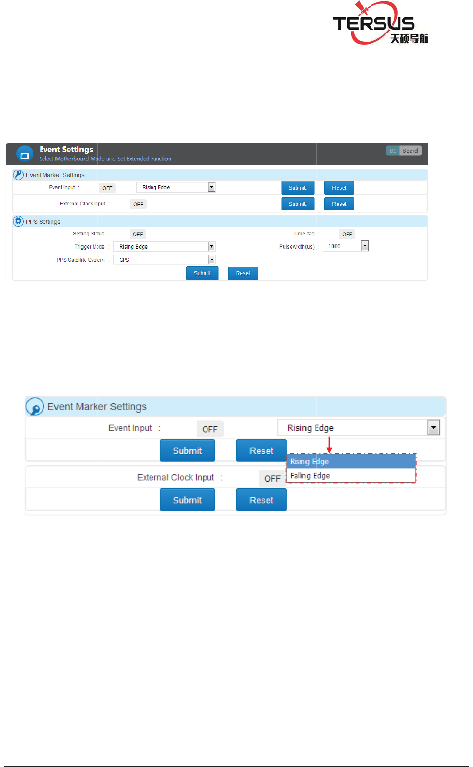
5RRP
Event
This s
e
¾Ex
ge
t
sw
PPS s
e
PPS s
w
Syste
m
When
you p
r
%XLOGLQJ/DQH
settin
g
s
e
ctor will
ternal Cl
o
t
device c
o
itch shou
l
e
tting: th
e
w
itch on/
o
m
(GPS,
B
turning o
n
r
efer get t
h
=KDQJKHQ
J
introduce
o
ck input:
o
nnected
t
l
d to be o
f
e
output
fr
o
ff, trigg
e
B
DS, GL
O
n
the tim
e
h
at info
fr
J
5RDG3XGRQJ
Figure 3
-
Event m
a
Figure 3
to input t
h
t
hen swit
c
f
f before
d
Figure 3-
3
fr
equency
e
r mode (
O
NASS),
T
e
-tag, this
fr
om five-
p
'LVWULFW6KDQJK
D
-
27 Remo
t
a
rker setti
n
-28. Eve
n
h
e extern
a
c
h on and
c
d
isconnec
t
3
0 Event Ma
r
is per se
c
Rising E
d
T
ime-tag,
P
data will
p
in serial
D
L
t
e control
n
g and P
P
n
t settings
a
l clock, p
c
lick Ǐ
S
t
ing the h
a
r
ker Setting
c
ond. Thi
s
d
ge or Fa
P
ulse wid
t
be outpu
t
port, the
P
S setting.
lease ma
k
S
ubmi
t
ǐ.
a
rdware.
s
tab is c
a
lling Edg
t
h.
t
as co
r
re
c
ǏFive-
p
k
e sure yo
u
Contraril
y
a
pable of
e), PPS
S
c
tion mes
s
p
in serial
t
u
have
y
, the
setting
S
atellite
s
age. If
t
ren
d
ǐ
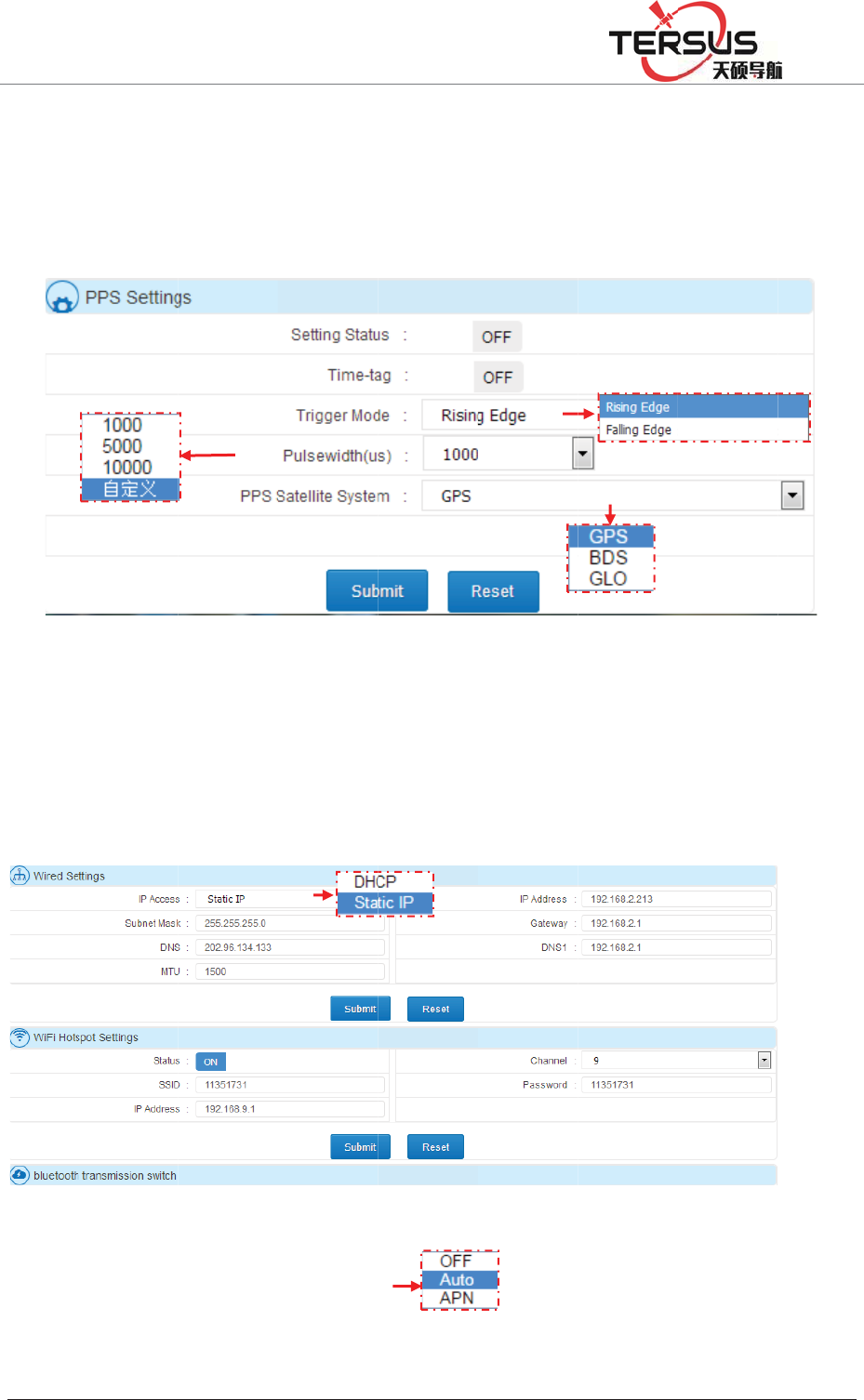
5RRP
shoul
d
10000
u
50000
0
Netw
o
Netw
o
server
%XLOGLQJ/DQH
d
be set
a
u
s. User
s
0
us.
o
rk Statu
s
o
rk settin
g
port setti
n
=KDQJKHQ
J
a
s COM2.
s
can als
o
s
and Set
t
g
consists
n
g and Fi
r
J
5RDG3XGRQJ
Pulse w
i
o
custo
m
Figure
t
in
g
of Wired
r
ewall swi
'LVWULFW6KDQJK
D
i
dth is o
p
m
ize the
v
3-31 PP
S
setting,
W
tch.
D
L
p
tional a
m
v
alue wi
t
S
setting
W
iFi Hots
p
m
ong 100
0
t
h the ra
n
p
ot settin
g
0
us, 500
0
n
ge of 1
g
, 2G/3G
0
us and
000 to
setting,
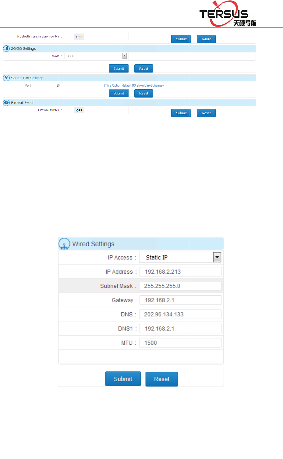
5RRP
Wired
DHC
P
autom
a
b
e set
etc. T
h
Wi-Fi
includ
i
%XLOGLQJ/DQH
setting:
T
P
(automa
t
a
tically s
e
manuall
y
h
e config
u
Hotspot
i
ng chann
=KDQJKHQ
J
Figu
r
T
here are
t
ic detect
i
e
t all para
m
y
in Static
u
ration pa
g
Setting:
el, passw
o
J
5RDG3XGRQJ
r
e 3-32 N
e
two way
s
i
ng) and
m
eters un
d
IP. Such
g
e is sho
w
Figure
3
several
p
o
rd, IP ad
d
'LVWULFW6KDQJK
D
e
twork St
a
s
to obtai
static IP
d
er DHC
P
as IP ad
d
w
n as figu
r
3
-33 Wire
d
p
arameter
s
d
ress of r
e
D
L
a
tus and
S
n IP add
r
(set ma
n
P
mode w
h
d
ress, sub
n
r
e 3-33.
d
settings
s
could
b
e
ceiver. T
h
S
etting
r
ess via
w
n
ually). T
h
h
ile all p
a
n
et mask,
b
e config
u
h
e default
w
ired con
n
h
e machi
n
a
rameters
h
Gatewa
y
u
red in t
h
setting f
o
n
ection,
n
e will
h
ave to
y
, DNS,
h
is tab
o
r SSID
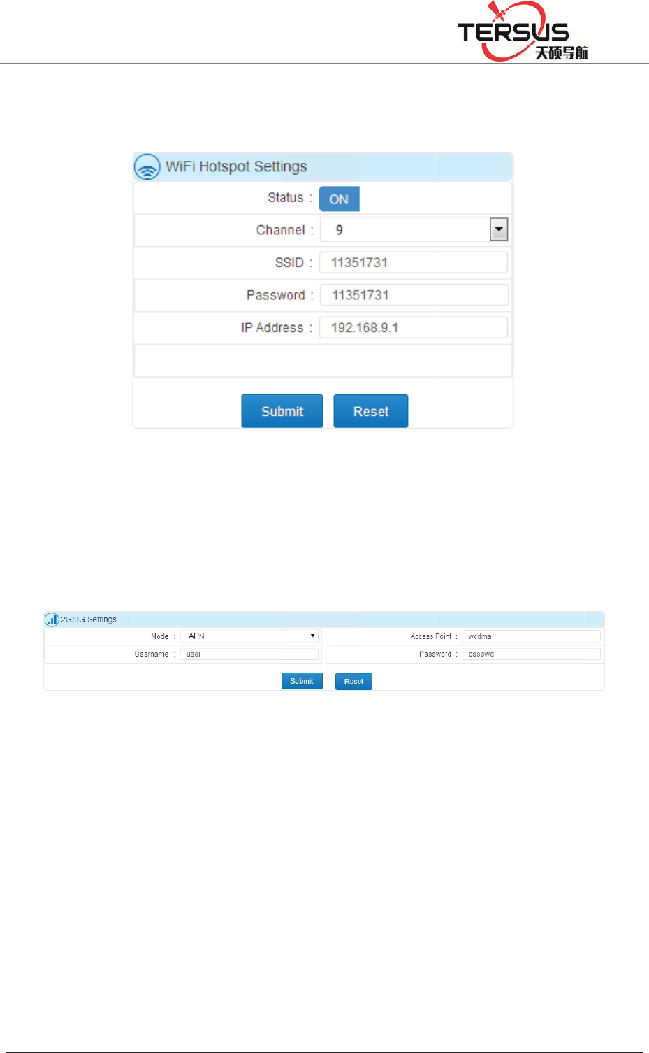
5RRP
and
P
admin
i
2G/3
G
or Au
t
in AP
N
Lo
g
F
i
Syste
m
and t
h
loggin
g
deleti
n
On th
e
%XLOGLQJ/DQH
P
assword
i
stration
p
G
setting:
t
t
o mode).
N
mode w
h
i
les
m
log files
h
ey list
f
g
in, pag
e
n
g. As wel
e
log files
=KDQJKHQ
J
are SN
p
age after
c
Fi
g
t
his tab is
Access p
h
ereas ev
e
records
a
f
ollowing
e
switchin
g
l as the n
e
page, sett
i
J
5RDG3XGRQJ
and ‘1
9
c
onnec
t
in
g
ure 3-34
about sw
i
oint, Use
r
e
rything
c
Figure 3
a
ll user op
time se
q
g
, setting
e
twork se
t
i
ng time
z
'LVWULFW6KDQJK
D
9
2.168.9.1
g Wi-Fi.
Wi-Fi H
o
i
tch on/of
f
r
name an
d
c
ould be s
e
-35 2G/3
G
eration lo
q
uence.
T
changing
,
t
ting, rest
a
z
one abov
e
D
L
’. Users
o
tspot Sett
f
2G/3G
fu
d
Passwo
r
e
t automa
t
G
Setting
gging file
T
he conte
n
,
data file
a
rt and F
W
e
the tabl
e
are abl
e
ing
fu
nction a
n
r
d must b
e
t
ically un
d
during t
h
n
t mainl
y
downloa
d
W
upgradi
n
e
to inspe
c
e
to vis
i
n
d setting
s
e
input m
a
d
er Auto
m
h
e runnin
g
y
contain
s
d
ing, trans
n
g, etc.
c
t all the l
o
i
t Web
s
(APN
a
nually
m
ode.
g
period
s
users
mitting,
o
g files
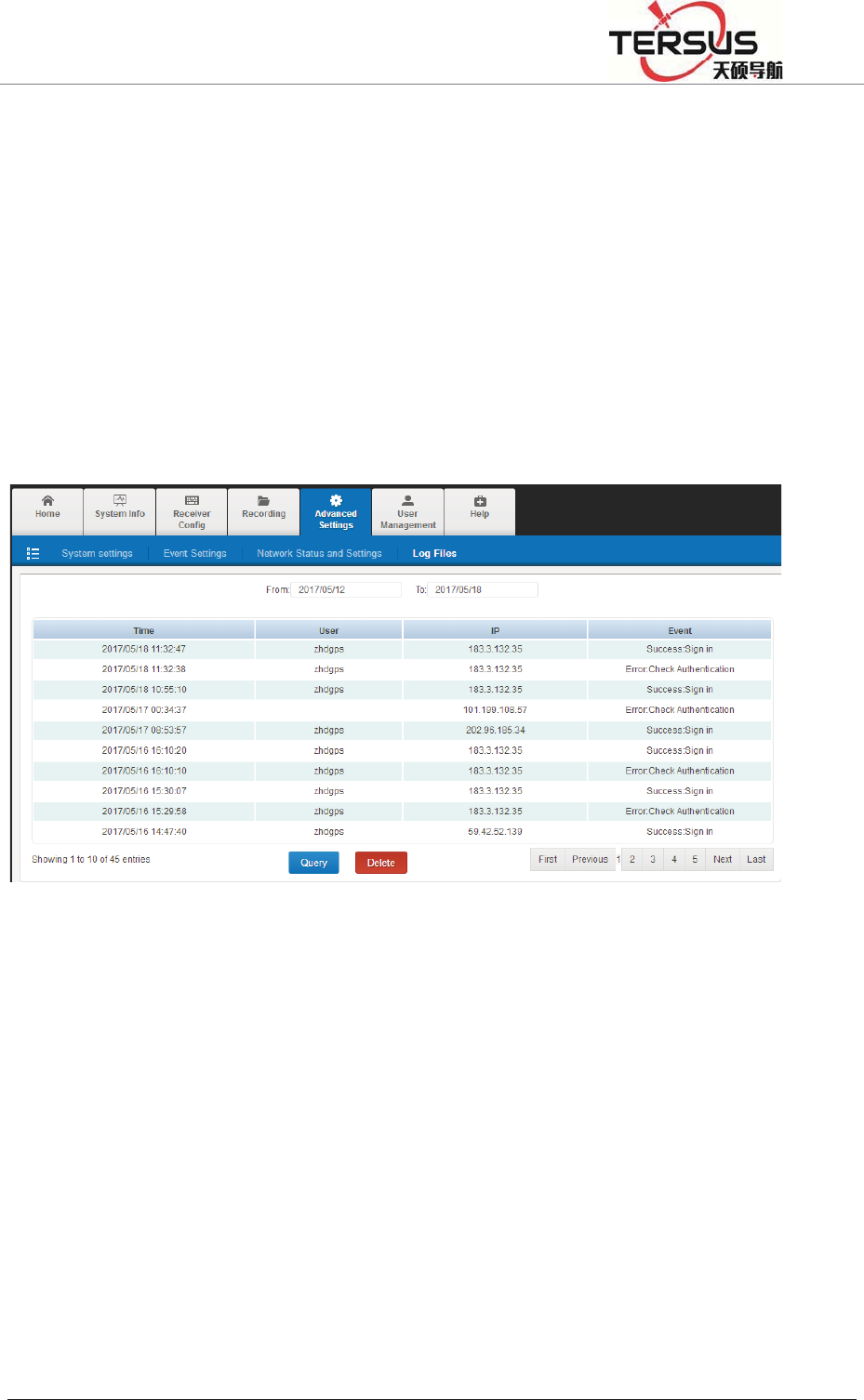
5RRP%XLOGLQJ/DQH=KDQJKHQJ5RDG3XGRQJ'LVWULFW6KDQJKDL
generated during this time zone. ǏDeleteǐ button is used to delete all the files
shown on the form.
Fields on the list:
1. Time: the time point of record under 24-hour system.
2. User: the logged user of corresponding operation.
3. IP: the IP address of recorded user.
4. Event: recorded event.
Figure 3-36 Log files
3.9 User management
This page is composed of Users and Admin.
Users
Changing current user’s password.

5RRP
Admi
n
This t
a
add/d
e
Addin
g
Mana
g
underl
i
be 6~
1
Deleti
n
%XLOGLQJ/DQH
n
a
b is aut
h
e
lete nor
m
g
new u
s
g
ement t
a
i
ne, starts
1
2 digits l
o
n
g user:
D
=KDQJKHQ
J
h
orized to
m
al users o
n
s
er: defi
n
a
b (user
with lett
e
o
ng). Clic
k
D
eleting a
c
J
5RDG3XGRQJ
Fig
u
administ
r
n
ly. Refe
r
n
e user
n
name m
u
e
rs with t
h
k
ingǏSu
b
c
count by
'LVWULFW6KDQJK
D
u
re 3-37
U
r
ator (ter
s
r
to chapt
e
n
ame an
d
u
se be c
o
h
e length
b
mitǐ t
o
clicking
D
L
U
sers
s
usgnss)
o
er
ǏUser l
d
passwo
r
o
mposed
of 5~16
d
o
finish th
e
ǏDelete
ǐ
o
nly and
b
og inǐ
f
r
d on th
e
of num
b
d
igits. Th
e
e
creating
ǐ
button.
b
eing all
o
f
or more
d
e
User
A
b
ers, lett
e
e
passwo
r
.
o
wed to
d
etails.
A
ccount
e
rs and
r
d must
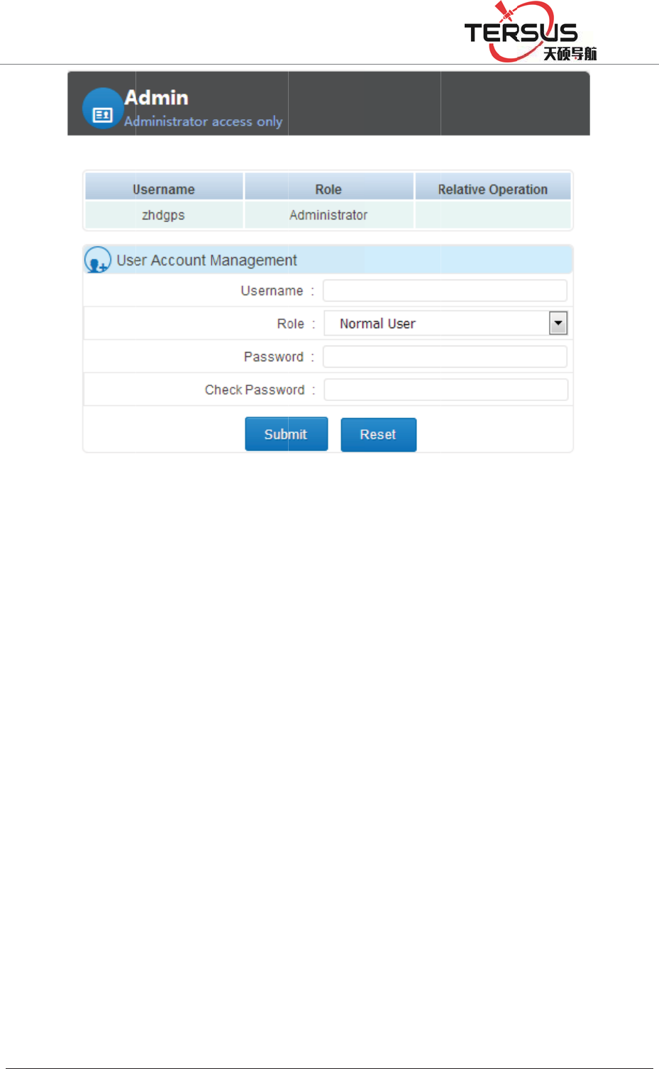
5RRP
4.1 A
r
GNSS
CORS
sensor
s
2G ne
t
%XLOGLQJ/DQH
r
chitect
u
receiver
and oth
e
s
, and co
n
t
work. Its
=KDQJKHQ
J
Cha
p
u
re mod
products
e
r fields.
n
nect to
c
architect
u
J
5RDG3XGRQJ
p
ter4
el
can be
u
Receive
r
c
entral se
r
u
re is gen
e
'LVWULFW6KDQJK
D
Basic
o
u
sed for
r
can co
n
r
vice area
e
rally sho
w
D
L
o
pera
t
ground
e
n
nect to
w
through
t
w
n in Fig
u
t
ions
e
nhancem
e
w
eather s
t
he netw
o
u
re 4-1:
e
nt syste
m
ensor an
d
o
rk cable
o
m
s and
d
other
o
r 3G /
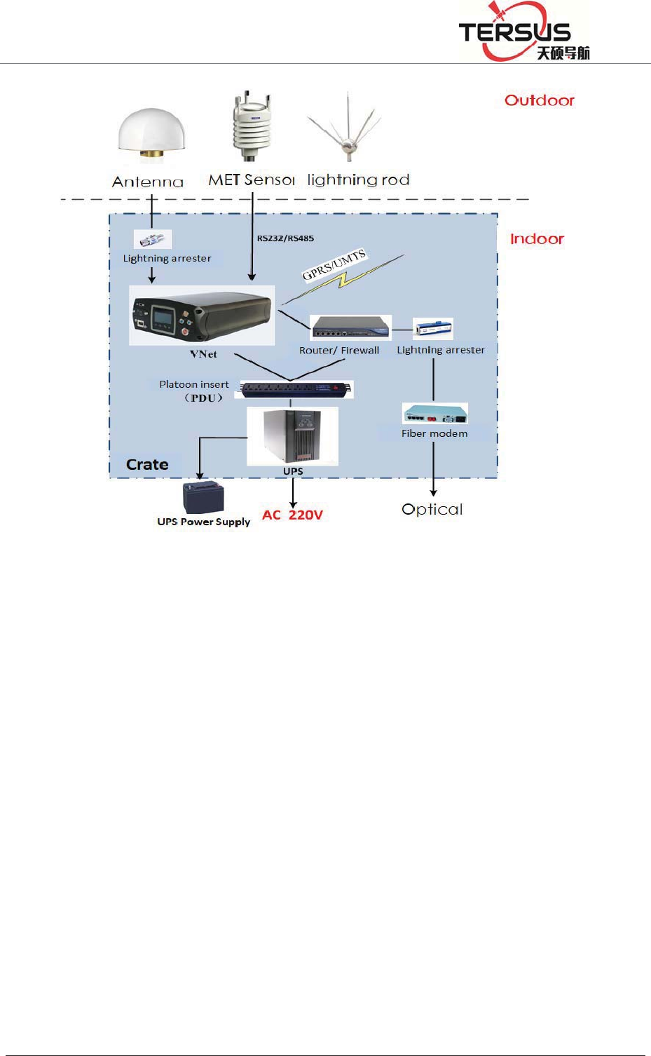
5RRP%XLOGLQJ/DQH=KDQJKHQJ5RDG3XGRQJ'LVWULFW6KDQJKDL
Figure 4-1. Architecture model
4.2 Basic composition and connection
The kit includes: GNSS receiver, VNet data cable (VS-3P), 3G / 2G antenna,
GNSS antenna cable, power adapter (CL-1233), cable. The connection is shown
in Figure 4-2
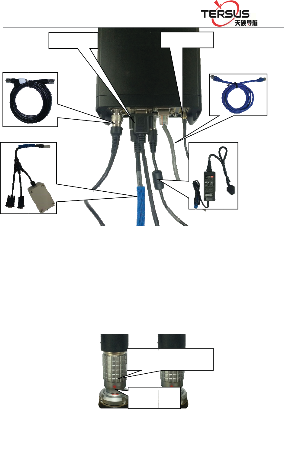
*1
6
9
6
5RRP
4.3 C
o
The G
N
extern
a
dot o
n
dama
g
Install,
6
6$QWHQQD
6
3FDEOH
%XLOGLQJ/DQH
o
nnecto
r
N
SS rece
i
a
l expans
i
n
cable co
n
g
e to the r
e
take SIM
/
FDEOH
=KDQJKHQ
J
F
r
install
a
i
ver have
i
on socke
t
n
nector i
s
e
ceiver an
F
i
/
TF card
DB9port
J
5RDG3XGRQJ
F
igure 4-2
a
tion
three sel
f
t
, power
i
s
aligned
w
d cable c
o
i
gure 4-3
C
'LVWULFW6KDQJK
D
Receiver
f
-locking
s
i
nput soc
k
w
ith the
r
o
nnector;
F
C
onnecto
r
Red do
t
Soc
k
D
L
connecti
o
s
ocket, re
s
k
et; show
n
r
ed dot o
n
F
igure 4-
3
r
installat
i
2G/3Ga
n
t
on conn
e
k
e
t
o
n
s
pectivel
y
n
as belo
w
n
receiver
3
:
i
on
&DEOH
3RZHU$GDS
n
tenna
e
cto
r
y
, five-pin
w
, ensure
socket, o
WHU
socket,
the red
r cause

5RRP%XLOGLQJ/DQH=KDQJKHQJ5RDG3XGRQJ'LVWULFW6KDQJKDL
1. Under the front panel is SIM / TF card installation slot, clockwise tighten the
screws, counterclockwise to loosen the screws.
2. Install SIM / TF card: SIM card chip is in the up layer, TF card chip is in the
second layer, oblique angle inward directly into; when you hear a sound,
installation finished.
3. take SIM / TF card: push the card, then the card pops up;
Figure 4-4 Installation / taking SIM / TF card
4.4 Network connection
1.LAN network connection
You can use the cable to connect the GNSS receiver with the LAN, input GNSS
receiver wired network IP address (default: 192.168.0.200) in the browser, then
enter the MatrixRTK series Web management system login interface.
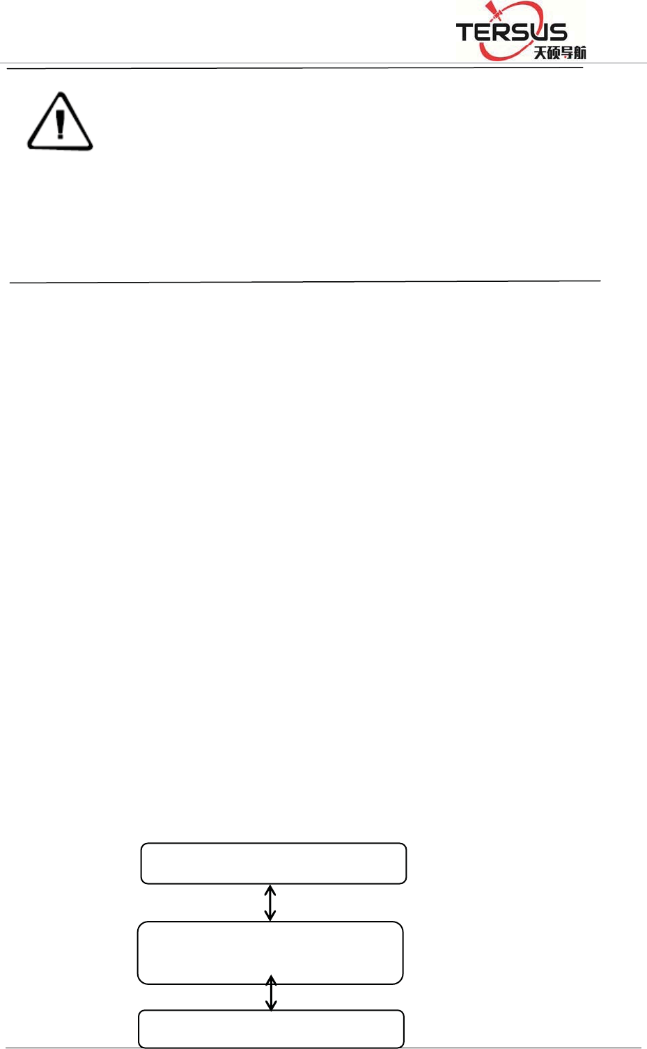
5RRP%XLOGLQJ/DQH=KDQJKHQJ5RDG3XGRQJ'LVWULFW6KDQJKDL
Notice: GNSS receiver default wired local IP is 192.168.0.200. If
the local area network segment is 192.168.0. ×, and the LAN does
not use 192.168.0.200IP, the GNSS receiver can be directly
connected to the LAN, LAN access through the IP 192.168.0.200 login; if the
local network segment is not 192.168.0. ×, such as LAN network segment
192.168.1. × or other (that is, GNSS receiver IP different from network segment),
you must add the network which segment is 192.168.0.x.
At present, often use optical fiber or ADSL to connect the network. Optical fiber
is usually with a fixed IP, and ADSL is usually a dynamic IP. Please refer to the
local telecommunications department for specific charges for optical fiber or
ADSL Internet access.
GNSS receiver and INTERNET can be directly accessed, you can also map
through the LAN external network IP to access.
Directly access method is relatively simple, in the local connection under the
Internet protocol, click ǏAdvancedǐ, in the pop-up interface, input the IP
address and gateway into WAN IP and gateway, as shown in Figure 4-5 below.
WANIP˖202.96.185.34
Fiber optic transponders or ADSL
MODEN
GNSSreceiverIPaddress˖202.96.185.34
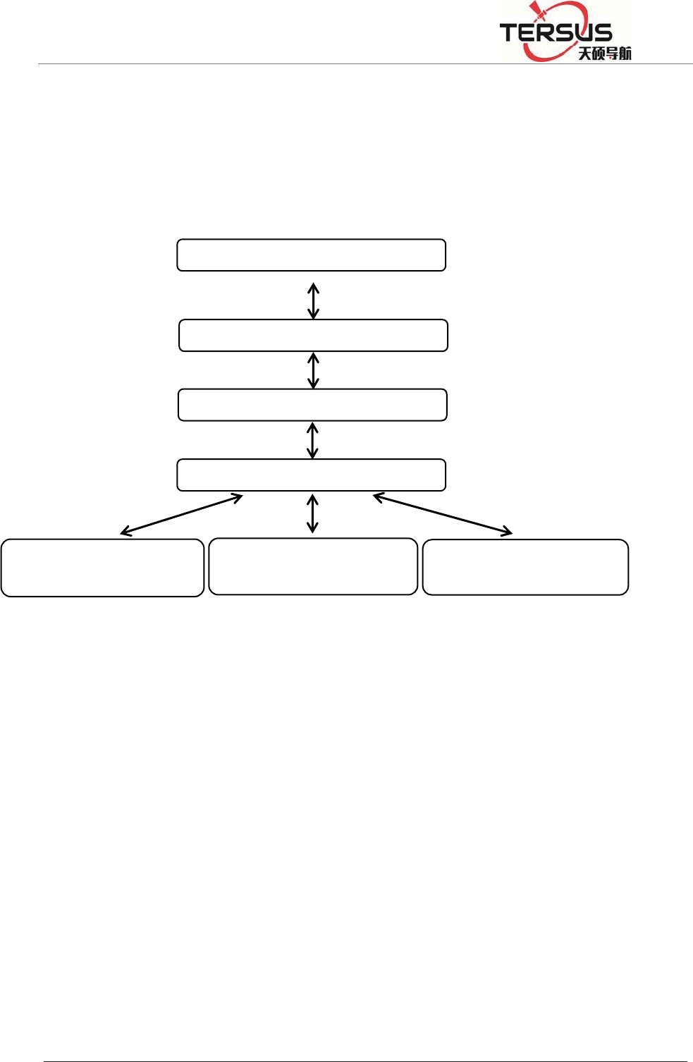
5RRP%XLOGLQJ/DQH=KDQJKHQJ5RDG3XGRQJ'LVWULFW6KDQJKDL
Figure 4-5 Line connection method
The GNSS receiver base station connects to the network by mapping the
external network IP. As shown in Figure 4-6:
Figure 4-6 Mapping to the external network connection
1.Change the IP of the GNSS receiver
There are two ways to change the IP address of a GNSS receiver: Manual
settings and match automatically acquire settings;
A. Manual settings
Firstly, obtain GNSS receiver's local IP, such as the default value is
192.168.0.200 (if you do not know the receiver's IP, double-click the "power
button" to open the LCD, then see the receiver IP address). Use a network cable
WANIP˖202.96.185.34
Fibero
p
tictrans
p
ondersorADSL
RouterIP˖192.168.1.1
Switch
GNSS receiver IPaddress ˖
192.168.168.1.200
Othercomputer'sIPaddress˖
192.168.1.101
Othercomputer'sIPaddress˖
192.168.1.102
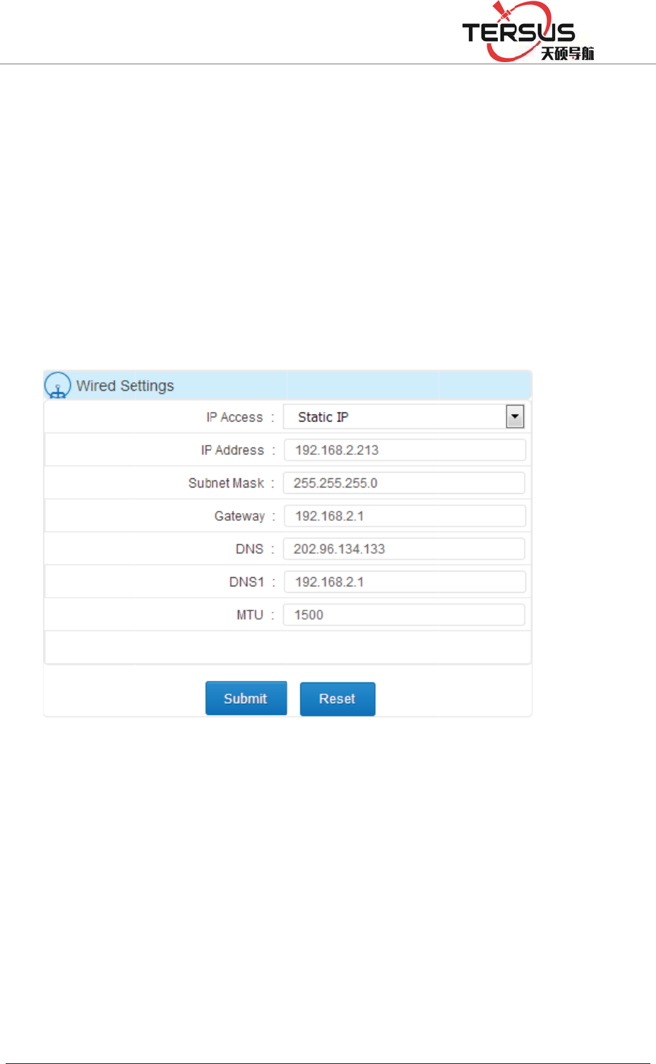
5RRP
to con
n
netwo
r
access
the Ǐ
GNSS
and C
l
B. Ma
t
Doubl
e
the m
e
b
utton
Recei
v
%XLOGLQJ/DQH
n
ect PC
a
r
k segme
n
the GNS
S
Advance
d
receiver'
s
l
ick Ǐsu
b
t
ch auto
m
e
-click th
e
e
nu optio
n
" to enter
v
er wire
d
=KDQJKHQ
J
a
nd GNSS
n
t, but dif
f
S
receive
r
d
Settings
s
IP addr
e
b
mitǐ; a
s
Figure 4
-
m
atically a
c
e
"power
b
n
s, click
and selec
t
d
networ
k
J
5RDG3XGRQJ
receiver,
f
erent IP;
r
WEB m
a
ǐ- ǏNe
t
e
ss, subne
t
s
shown i
n
-
7 Set the
c
quire set
t
b
utton" t
o
"right" s
e
t
Ǐwired
n
k
mode
'LVWULFW6KDQJK
D
set PC I
P
such as 1
9
a
nagemen
t
work Set
t
t
mask, g
a
n
Figure 4
IP addres
t
ings
o
open the
e
lec
t
Ǐne
t
n
etworkǐ
changed
D
L
P
and GN
S
9
2.168.0.
1
t system
u
t
ingsǐ -
a
teway,
D
-7:
s settings
LCD, cli
c
t
work set
t
, click th
e
as ǏD
H
S
S receiv
e
1
48, then
t
u
sing IP 1
ǏCable
S
D
NS (DN
S
manually
c
k the "F
n
t
ingsǐ,
c
e
"power
b
H
CP ǐT
h
e
r IP in t
h
t
he PC lo
g
92.168 .0
.
S
ettingsǐ
,
S
no need
n
button"
t
c
lick the
b
utton" t
o
h
e syste
m
h
e same
g
in and
.
200, at
,
set the
to set),
t
o enter
"power
o
set the
m
will
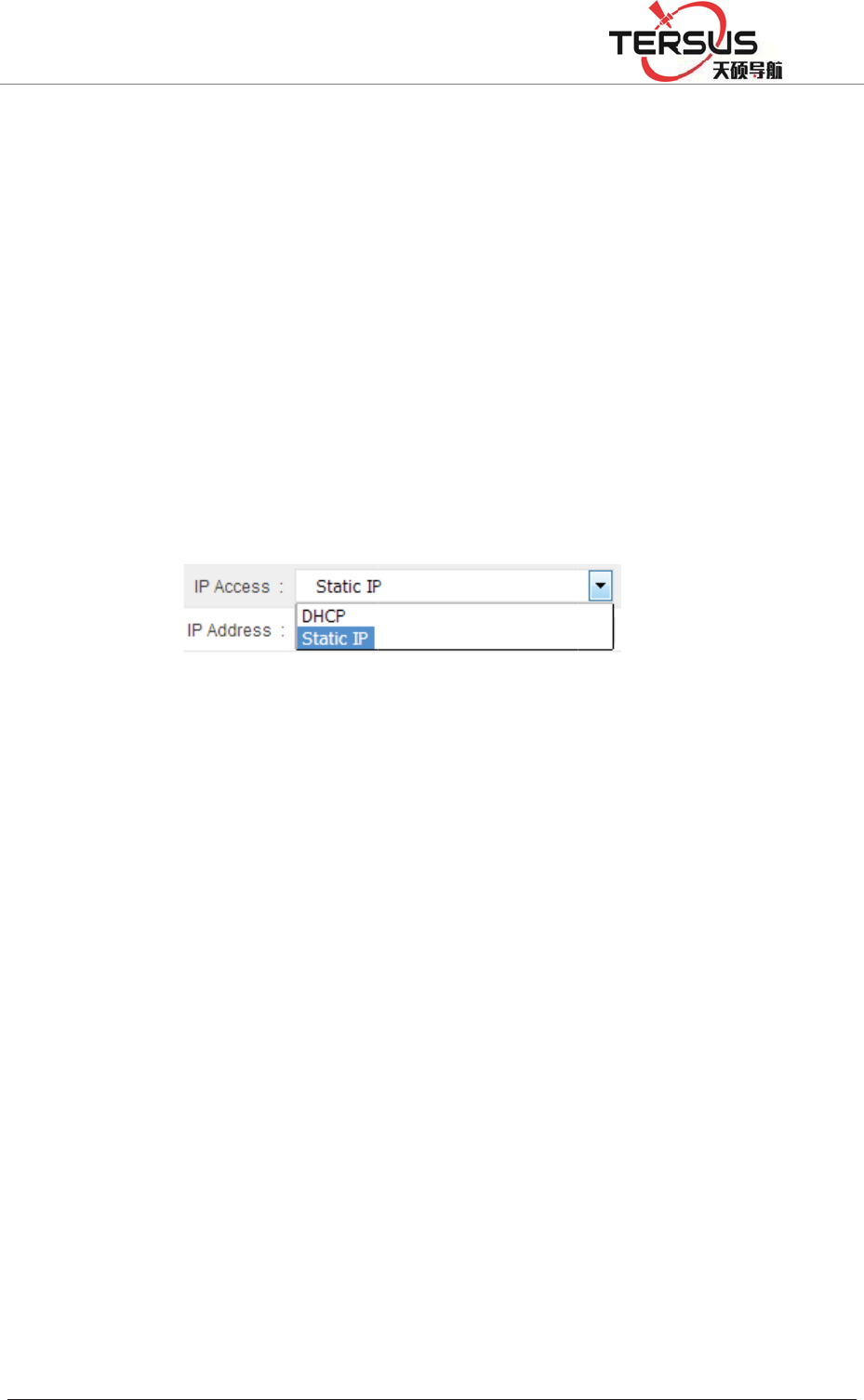
5RRP
autom
a
"Fn b
u
record
throug
ǏNet
w
IPǐ,
a
to set)
,
2. Ma
p
Open
t
up fol
l
netwo
r
Enter
name:
Set th
e
addres
Wi-Fi
n
Wi-Fi
mana
g
%XLOGLQJ/DQH
a
tically o
b
u
tton" to
i
t
; Then
h the aut
w
ork Sett
i
a
nd set th
e
,
and clic
k
Fi
g
p
ping the
e
t
he page
a
l
owing di
r
k admini
s
the user
n
admin, p
a
e
local L
A
s.
n
etwork
network
g
ement sy
s
=KDQJKHQ
J
b
tain the I
return to
the PC c
a
omaticall
y
i
ngsǐ-
Ǐ
e
receiver
k
Ǐsubmi
t
g
ure 4-8
A
e
xternal
n
a
nd enter
t
alog box
s
trator).
n
ame an
d
a
ssword:
a
A
N LAN
can be
o
s
tem, W
E
J
5RDG3XGRQJ
P and wir
the stat
u
a
n access
y
obtaine
d
Ǐ
Cable Se
t
IP addre
s
t
ǐ; Figur
e
A
utomatic
a
n
etwork I
P
t
he addre
s
(if you c
d
passwo
r
a
dmin.
port, and
o
perated
E
B manag
e
'LVWULFW6KDQJK
D
ed netwo
r
u
s display
the GNS
S
d
IP add
r
t
tings, Ǐ
I
s
s, subnet
e
4-8:
a
lly obtai
n
P
s
s: http: //
1
an’t ente
r
r
d, the ge
n
set the I
P
by LCD
e
ment sy
s
D
L
r
k-related
main in
t
S
receive
r
r
ess. Go
t
I
P Acquis
i
mask, ga
t
n
the IP a
d
1
92.168.1
r
the logi
n
n
eral TP
-
P
address
with bu
t
s
tem also
paramete
r
t
erface, c
h
r
web ma
n
t
oǏAdva
n
i
tion Mo
d
t
eway, D
N
d
dress sett
i
.1 (defaul
t
n
interfac
e
-
LINK in
i
as the
G
t
ton oper
a
can set t
h
r
s; then p
r
h
eck the
n
agement
n
ced Sett
i
d
eǐselect
N
S (DNS
n
i
ngs
t
IP addre
e
, please
i
tial defa
u
G
NSS rec
e
a
tion an
d
h
e Wi-Fi
n
r
ess the
IP, and
system
i
ngsǐ-
ǏStatic
n
o need
ss) pop
consult
u
lt user
e
iver IP
d
WEB
n
etwork
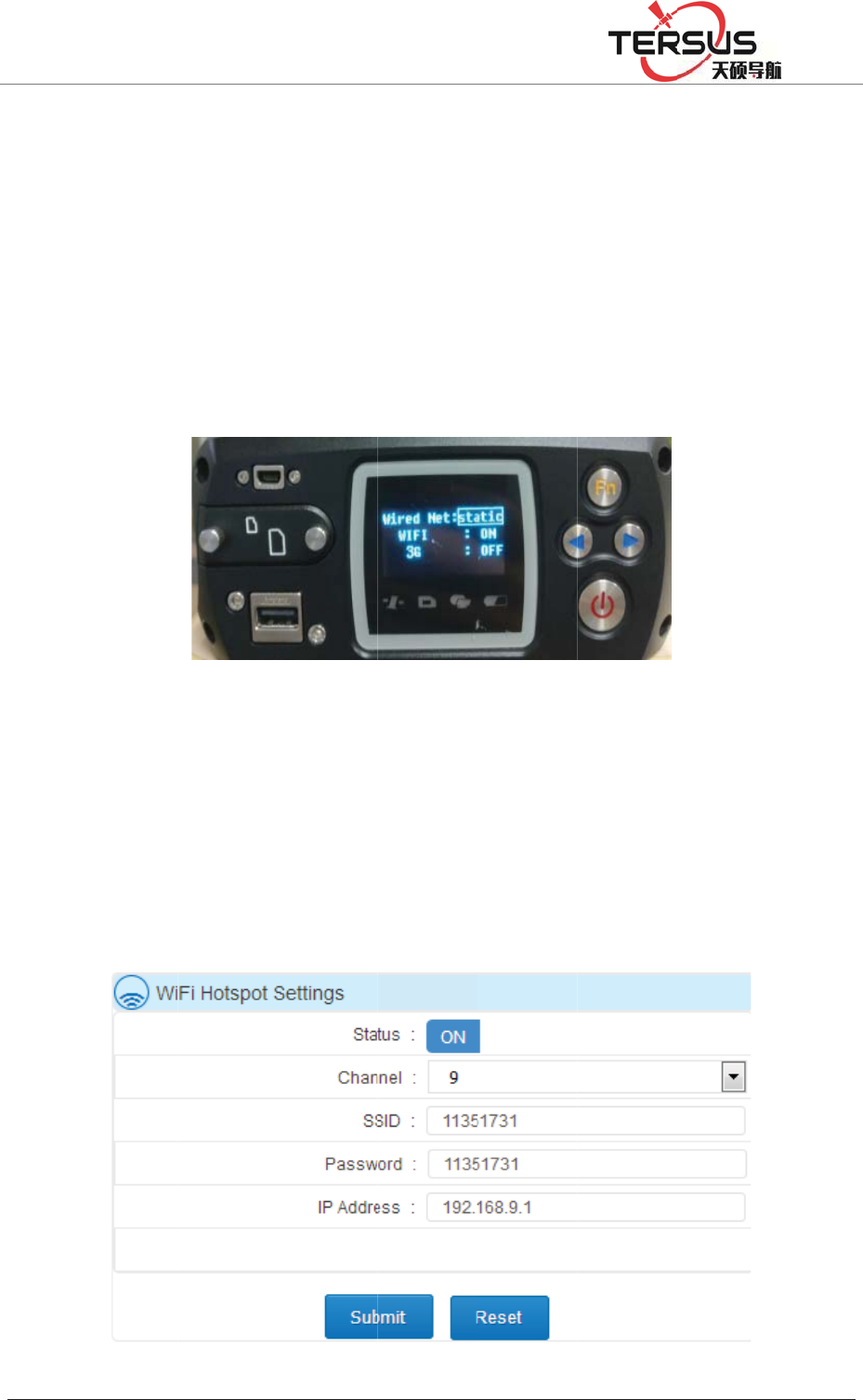
5RRP
passw
o
A. LC
D
LCD
d
b
utton
ǏWI
F
shown
B.WE
B
ǏAd
v
4-10:
%XLOGLQJ/DQH
o
rd, chan
n
D
displa
y
d
isplay, c
l
" to selec
t
F
Iǐ, Cli
c
in Figur
e
Fig
u
B
mana
g
v
anced Se
t
=KDQJKHQ
J
n
el and lo
g
y
and key
o
l
ick the "
F
t
Ǐnetwor
k
c
k the "p
o
e
4-9:
u
re 4-9 L
C
g
ement s
y
t
tingsǐ-
Ǐ
J
5RDG3XGRQJ
g
in IP ad
d
o
peration
:
F
n button
k
settings
ǐ
o
wer butt
o
C
D butto
n
y
stem: l
o
Ǐ
Networ
k
'LVWULFW6KDQJK
D
d
ress;
:
d
ouble-
c
" to ente
r
ǐ
, click t
h
o
n" to co
n
n
operatio
n
o
g in W
E
k
Settings
ǐ
D
L
c
lick the "
p
r
the men
u
h
e "power
n
trol the
n
Wi-Fi n
e
E
B man
a
ǐ
-ǏWifi
p
ower bu
t
u
options
,
button" t
o
Wi-Fi ne
t
e
twork on
a
gement
hot se
t
ǐ;
t
ton" to o
p
,
click th
e
o
enter an
d
t
work sw
i
/ off
system,
s
shown i
n
p
en the
e
"right
d
select
i
tch; as
s
et the
n
Figure
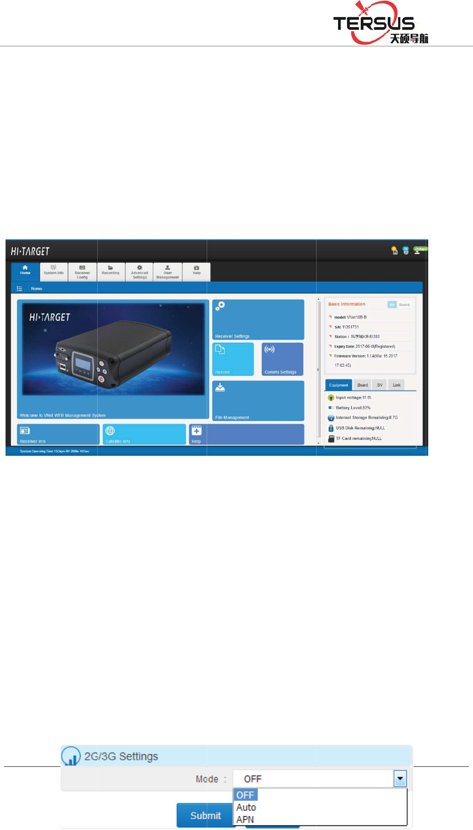
5RRP
After
o
the W
i
the IP
interfa
with t
h
2G / 3
G
FTP p
u
need t
Settin
g
If usi
n
and su
b
APN
l
%XLOGLQJ/DQH
F
i
o
pening
M
i
-Fi accou
address
o
ce after l
o
h
e PC sid
e
G
networ
k
u
sh, remo
t
o connec
t
g
sǐ-ǏN
e
n
g Non-
A
b
mit, the
s
l
ine card
,
=KDQJKHQ
J
i
gure 4-1
0
M
atrixRT
K
nt then e
n
o
f the GN
S
o
gging in
e
)
Figure 4
-
k
t
e control
t
the 3G
e
twork Se
A
PN (gree
n
s
ystem w
i
,
the use
r
J
5RDG3XGRQJ
0
Web ma
n
K
's Wi-Fi
h
n
ter the p
a
S
S receiv
e
is shown
-
11 Mobil
e
and net
w
antenna,
ttingsǐ,
o
n
line) ph
o
i
ll autom
a
r
s need
t
'LVWULFW6KDQJK
D
n
agement
h
otspot, u
s
a
ssword (
d
e
r (defaul
t
in Figur
e
e
device
h
w
ork trans
m
install th
e
o
pen 2G
/
o
ne card,
a
tically di
a
t
o obtain
D
L
system
W
s
ers can
u
d
efault: S
N
t
: 192.16
8
e
4-11 (A
c
h
ome pag
e
m
ission u
s
e
SIM c
a
3G netw
o
selectǏ2
G
a
l and con
n
the acc
e
W
i-Fi setti
n
u
se mobil
e
N
number
)
8
.9.1) The
c
count an
d
e
interfac
e
s
ing 2G /
3
a
rd, unde
r
o
rk.
G
/ 3G se
t
n
ect;
e
ss point,
n
gs
e
device t
o
)
. And th
e
mo
b
ile t
e
d
passwo
r
e
3
G netw
o
r
theǏA
d
t
tingsǐ-
Ǐ
user na
m
o
search
e
n enter
e
rminal
r
d same
o
rk, you
d
vanced
Ǐ
Autoǐ
m
e and

5RRP%XLOGLQJ/DQH=KDQJKHQJ5RDG3XGRQJ'LVWULFW6KDQJKDL
password from the network operator, and select ǏAPNǐ mode to fill in the
access point, user name and password (as shown below), click Ǐsubmitǐ,
system Will automatically load the data and connect the data; shown in Figure
4-12:
Figure 4-12 2G / 3G network settings
4.5 LCD and button operation
Table 4-1 LCD and button operation
Function Operation Content
Turn on / off
the LCD
Double-click
the power
button
Display the home page of the status information
Switch status
information
Click the
left/right button
View the status information of the receiver
Switch status
and settings
display
Click the Fn
button
Status and setting interface loop switch
Return to the
upper menu /
Cancel
Click the Fn
button
Switch the
menu
Click the
left/right button
Menu page: Data record, network setting, data download,
system setting;
System Settings menu page: Firmware upgrade, restore the
default IP, reset, restoring the motherboard, the language
selection; operating cycle through the menu;
Go to the
menu
subordinate
Click the power
button
The main menu: Data record, network setting, data download,
system setting
System Setup menu: Upgrade firmware, restore default IP,

5RRP%XLOGLQJ/DQH=KDQJKHQJ5RDG3XGRQJ'LVWULFW6KDQJKDL
restore factory settings, restore motherboard, language
selection;
Data record Click the
left/right button
Move options
Click the power
button
Modify the record mode or confirm the settings
Network
settings
Click the
left/right button
Move options
Click the power
button
Modify the parameter value
Data
download
Click the power
button
Set, move to the next step and confirm the settings
Click the
left/right button
Password: left button PLUS 1, right minus 1; number of days:
switch the number of days options;
U disk
upgrade
Click the power
button
Upgrade firmware, firmware to be placed in the root directory
of U disk;
language
selection
Click the power
button Click the
left/right button
Restore the
default IP;
Reset; Reset
the
motherboard
Click the power
button
Reset: Click the "Power button" to enter the confirmation reset
prompt page, click the "power button"; Reset the motherboard
and restore the default IP the same.
Notice:
1, if 60s without operation, the system automatically shut down the
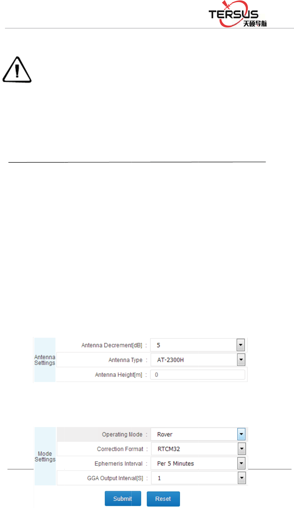
5RRP
4.6 S
e
Login
or Cli
c
1. Ant
e
Accor
d
attenu
a
syste
m
2. Bas
e
Set th
e
%XLOGLQJ/DQH
LCD a
n
2,
b
utt
o
delete
d
3, whe
curren
t
4, If
Imme
d
e
t the b
a
WEB ma
n
c
k Ǐwor
k
e
nna sett
i
d
ing to t
h
a
tion, ant
e
m
introduc
e
e
settin
g
s
e
work m
o
=KDQJKHQ
J
n
d open t
h
o
n set dat
d
after res
t
n the tex
t
t
was sele
c
the inte
r
d
iately tak
a
se stati
o
n
agemen
t
k
modeǐ
i
n
g
s
h
e actual
p
e
nna typ
e
ed
ǐ-Ǐw
o
o
de of the
J
5RDG3XGRQJ
h
e indicat
o
a record i
t
art; but t
h
t
or icon i
c
ted, you
r
face do
e
e effect a
f
o
n
t
interface
-ǏSettin
g
p
arameter
s
e
, and an
t
o
rk mode
ǐ
Figure 4-
reference
'LVWULFW6KDQJK
D
o
r light;
s tempor
a
h
e data wi
l
s surroun
d
can modi
f
e
s not
h
f
ter modi
f
, just clic
k
g
sǐto se
t
s
of the a
n
t
enna hei
g
ǐ
-Ǐrefer
e
13 Anten
n
station a
s
D
L
a
ry record
,
l
l not lost
.
d
ed by a
b
f
y or ente
r
h
ave con
f
f
ication, s
u
k
the Ref
e
;
n
tenna in
f
g
ht (refe
r
e
nce stati
o
n
a setting
s
s
ɋroverɌ
,
the reco
r
.
b
ox, whic
r
the subo
r
f
irm opti
o
u
ch as net
w
e
rence sta
t
f
ormatio
n
r
to ǏW
E
o
n setting
s
s
and sub
m
r
d setting
c
h means
t
r
dinate se
t
o
n, that
w
ork sett
i
t
ion setti
n
n
, set the
a
E
B mana
g
s
ǐ); Figu
r
m
it it; as s
h
will be
t
hat the
t
tings;
means
i
ngs.
n
gs link
a
ntenna
g
ement
r
e 4-13:
h
own in
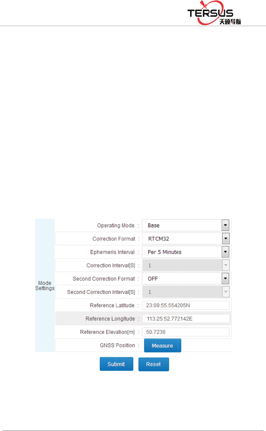
5RRP
Figure
Set t
h
ǏCor
r
RTC
M
Ǐeve
r
30 mi
n
elevat
i
4.7 A
d
Log i
n
%XLOGLQJ/DQH
4-14:
h
e work
m
r
ection F
o
M
32, BIN
E
r
y 30 min
u
n
utes for
s
i
on, and c
l
d
d data
n
WEB m
a
=KDQJKHQ
J
m
ode of
o
rmatǐac
c
E
X for se
l
u
tesǐ (E
v
s
election)
,
l
ick Ǐsu
b
record
a
nageme
n
J
5RDG3XGRQJ
Figure 4
the refe
r
c
ording to
l
ection),
e
v
ery 1 mi
n
,
manuall
y
b
mitǐ; F
Figure
4
n
t system
'LVWULFW6KDQJK
D
-14 Rove
r
r
ence stat
actual ne
e
phemeri
s
n
ute, ever
y
y
enter th
e
igure 4-1
5
4
-15 Base
interface,
D
L
r
Settings
ion as
Ǐ
eds (OFF
,
s
interval
y
5 minut
e
e
known
l
5
:
settings
click on
Ǐ
Base St
,
CMR, R
T
is recom
m
e
s, every 1
l
atitude a
n
the data
r
t
ationǐ,
T
CM, RT
C
m
ended t
o
5 minute
s
n
d longit
u
r
ecord qu
i
choose
C
MV3,
o
select
s
, every
u
de and
i
ck link
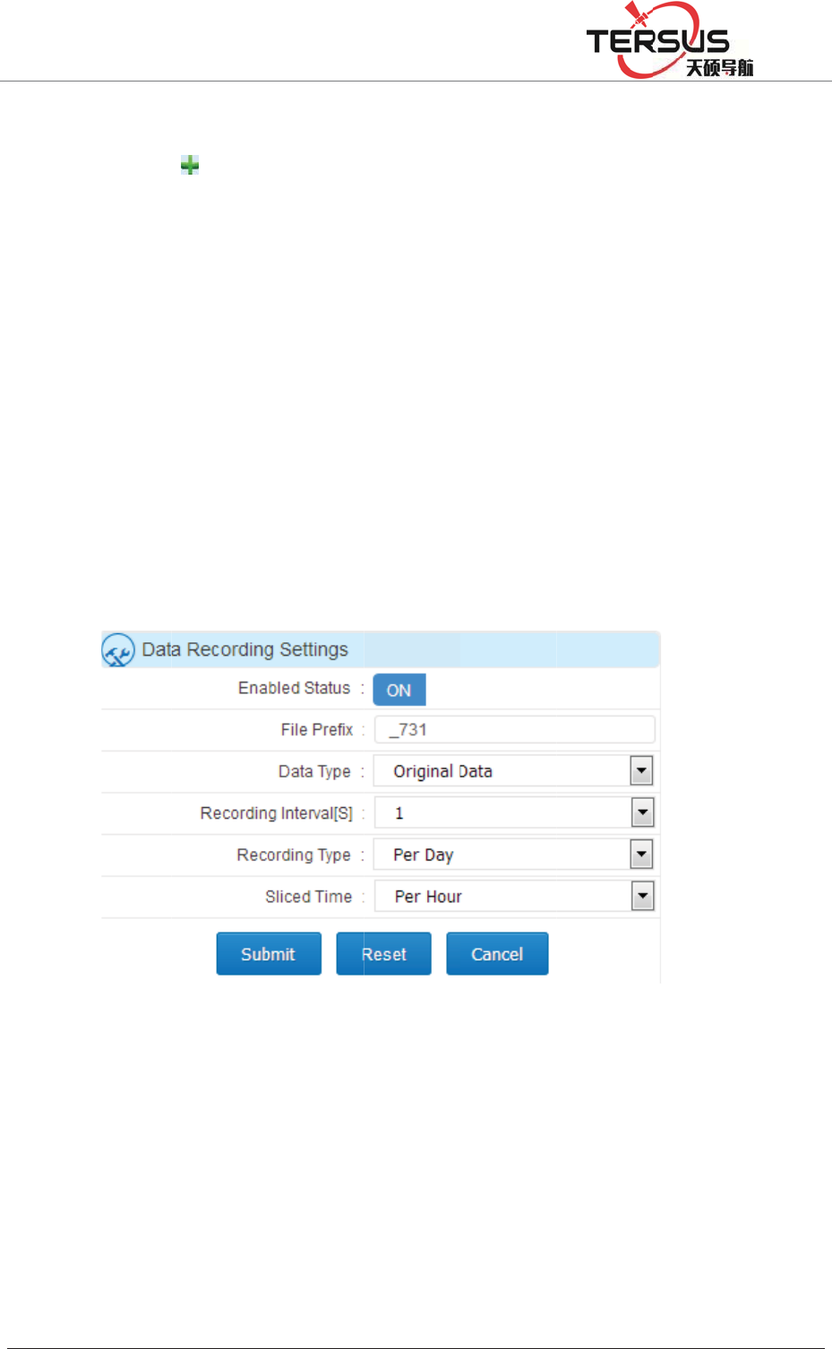
5RRP
or clic
k
Click
Loggi
n
ǏIde
n
numb
e
accor
d
are da
i
shown
Recor
d
or rec
o
%XLOGLQJ/DQH
k
Ǐwor
k
the butto
n
n
g Settin
g
n
tification
e
rs added
b
d
ing to a
c
i
ly, man
below:
d
every d
a
o
rd a file
e
=KDQJKHQ
J
k
modeǐ
n
in th
e
g
sǐdialo
g
nameǐ
b
y the sy
s
c
tual nee
d
ual and
a
y (24 ho
u
e
very two
Figur
e
J
5RDG3XGRQJ
- Ǐdata
e
upper l
e
g
box, en
a
(the first
f
s
tem ) Ǐ
D
d
s, Ǐrec
o
planned
w
u
rs record
hours), a
s
e
4-16 Da
i
'LVWULFW6KDQJK
D
recor
d
ǐ
t
e
ft corne
r
a
ble the
s
f
our digit
s
D
ata type
ǐ
o
rd interv
a
w
ays, jus
t
without
b
s
shown i
n
i
ly Data
L
D
L
t
o set;
r
of the i
n
s
tatus dia
l
s
and the
l
ǐ
Select
a
l [S]ǐis
r
t
clickǏs
u
b
reak up,
o
n
Figure 4
L
ogging S
e
n
terface t
o
l
to ǏO
N
l
ast four o
Ǐraw dat
a
r
ecomme
n
u
bmitǐ.
R
o
r record
a
-16:
e
ttings
o
pop up
N
ǐ, set
t
f the file
i
a
ǐ or Ǐ
n
ded 1.Ǐ
r
R
ecord
w
a
file eve
r
ǏData
t
he file
i
s serial
Rinexǐ
r
ecor
d
ǐ
w
ays are
r
y hour,
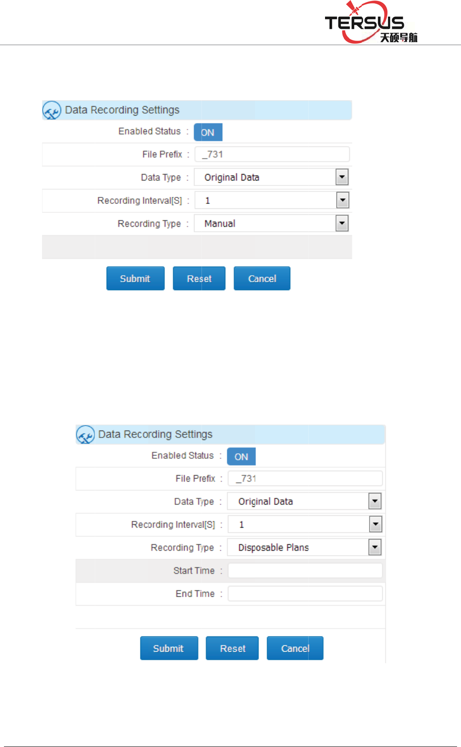
5RRP
Manu
a
Figure
Dispo
s
shown
4.8 A
d
%XLOGLQJ/DQH
a
l recordi
n
4-17:
s
able pla
n
in Figur
e
F
d
d netw
o
=KDQJKHQ
J
n
g (manu
a
Figur
e
n
records
(
e
4-18:
F
igure 4-
1
o
rk tra
n
J
5RDG3XGRQJ
a
l control
e
4-17 M
a
(
accordin
g
1
8 Dispos
a
n
smissio
n
'LVWULFW6KDQJK
D
data rec
o
a
nual data
g
to the
n
a
ble plan
d
n
D
L
o
rds to en
a
logging s
n
eeds to s
e
d
ata loggi
a
ble or d
i
ettings
e
t the ti
m
ng settin
g
i
sable), s
h
m
e start a
n
g
s
h
own in
n
d end),

5RRP%XLOGLQJ/DQH=KDQJKHQJ5RDG3XGRQJ'LVWULFW6KDQJKDL
Log in WEB management system interface, click the network transmission
quick link or click Ǐwork modeǐ - Ǐnetwork transmissionǐto set;
Click the button in the upper left corner of the interface , the ǏNetwork
Transfer Settingsǐdialog box will pop up, put the state dial to ǏONǐ,
ǏEncryption state ǐsets According to the actual need , ǏNetwork ǐ
Recommended ǏWiredǐ (wiredǃWi- Fiǃ2G / 3G), Ǐtransmission protocolǐ
sets according to the actual need˄to understand the transmission protocol, please
go to the Ǐwork modeǐ - Ǐnetwork transmissionǐof theǏWEB management
system introductionǐ˅, Ǐdata typeǐsets According to the actual needs (choose
from raw data, NMEA-0183, correction data, RS232 serial data, RS485 serial
port data ) ǏTransmission interval [S]ǐ only the raw data have This option,
recommend to use 1 (0.05,0.1,0.2,0.5,1,2,5,10,15,30,60 transmission interval [S]
for the user to choose), the server IP , Port, user name and other settings are
related to transmission protocol, see the specificǏwork modeǐ -Ǐnetwork
transmissionǐof theǏWEB management system introducedǐ; set as shown in
Figure 4-19:
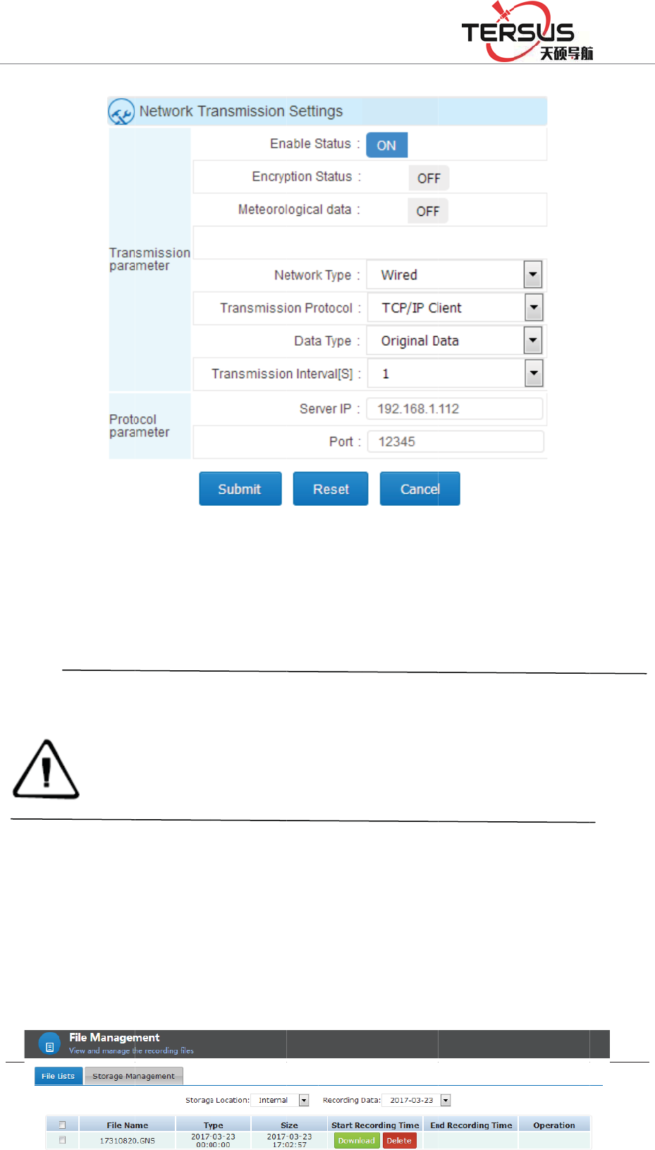
5RRP
4.9 D
a
Norm
a
In the
W
locati
o
%XLOGLQJ/DQH
Noti
c
1. T
h
2.w
h
a
ta dow
n
a
l downl
o
W
EB ma
n
o
n of the
d
=KDQJKHQ
J
Fig
u
c
e:
h
ree kind
s
IP addres
s
h
en openi
n
into the s
e
n
load
o
ad
n
agement
d
ata stora
g
J
5RDG3XGRQJ
u
re 4-19 A
d
s
of netw
o
s
transmit
n
g the sec
o
e
cond cor
r
system
Ǐ
g
e and th
e
'LVWULFW6KDQJK
D
d
d netwo
r
o
rk mode
s
ted to the
o
nd corre
c
r
ection.
Ǐ
File Ma
n
e
date of t
h
D
L
r
k transm
i
s
can exis
t
server ca
n
c
tion outp
u
agemen
t
ǐ
h
e record
;
i
ssion
t
at the s
a
n
not be t
h
u
t, the Ǐ
o
ǐ
- ǏFile
;
pop up i
a
me time,
h
e same.
o
riginal d
a
Lis
t
ǐ, se
ntraday d
but the
a
taǐturn
lec
t
the
ata list,
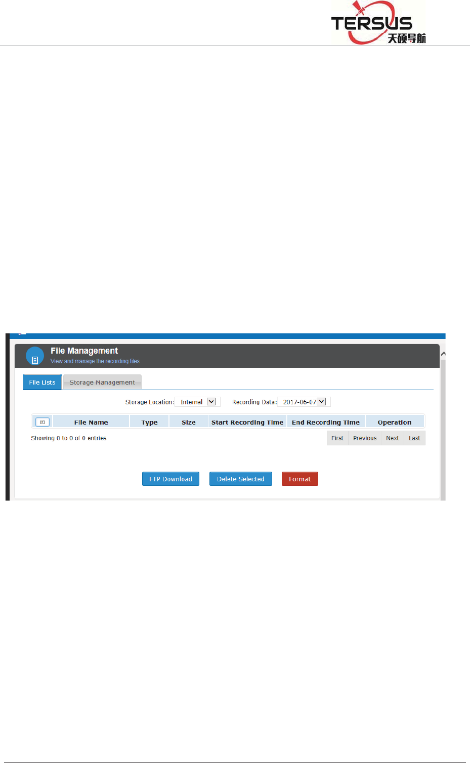
5RRP%XLOGLQJ/DQH=KDQJKHQJ5RDG3XGRQJ'LVWULFW6KDQJKDL
click the right side of data list Ǐoperationǐ-Ǐdownloadǐ then download the
corresponding data; as shown in Figure 4-20:
Figure 4-20 Normal data download
FTP download
Before FTP download data, make sure the routing and LAN has opened the FTP
port; In the WEB management system Ǐfile managementǐ- Ǐfile listǐ,click
ǏFTP downloadǐbutton, automatically go to the FTP download list; the home
page download list shown in Figure 4-21:
Figure 4-21 FTP download directory
Click the catalog folder of the storage (select it according to the actual
requirements), enter the date list, and then click the corresponding date
FTP push
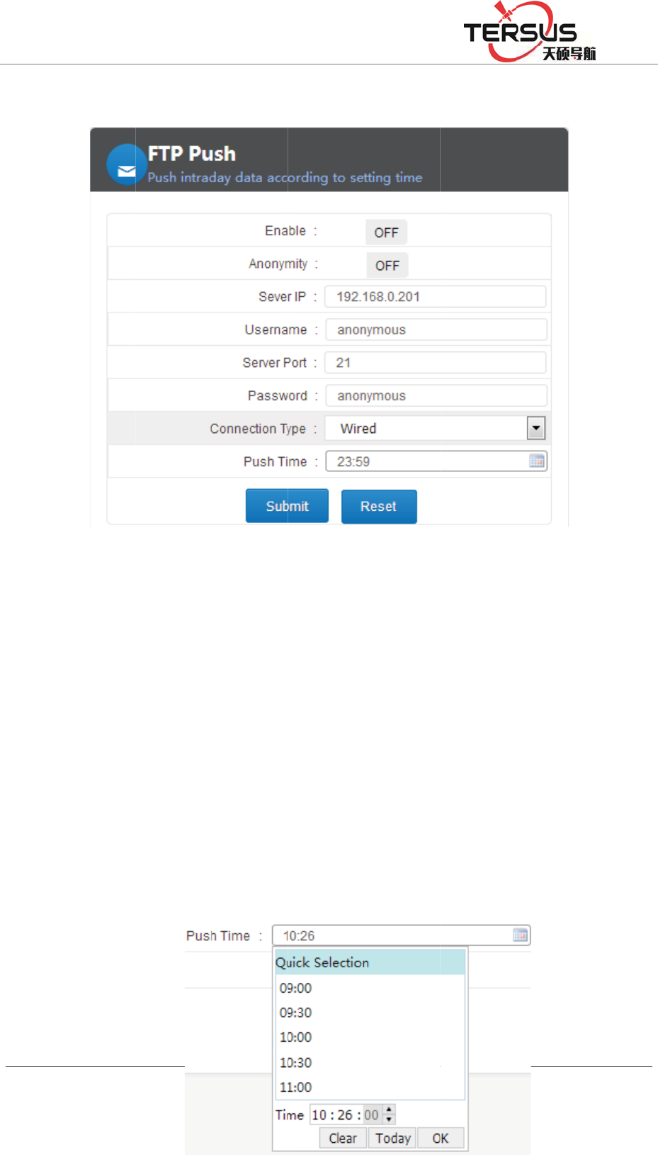
5RRP
FTP p
u
shown
First,
e
server
cable,
W
Push t
i
click,
p
selecti
o
%XLOGLQJ/DQH
u
sh can p
e
in Figur
e
e
nable th
e
IP and p
o
W
i-Fi or
3
i
me inter
fa
p
op-up ti
m
o
n box, s
=KDQJKHQ
J
e
riodicall
y
e
4-22:
e
FTP p
u
o
rt (data b
e
3
G) and p
u
fa
ce for q
u
m
e check
elect the
J
5RDG3XGRQJ
y
push th
e
Figur
e
u
sh functi
o
e
pushed
t
u
sh time,
u
ick selec
t
box; you
desired
h
'LVWULFW6KDQJK
D
e
data file
e
4-22 FT
P
o
n, set a
n
t
o FTP se
r
as shown
t
ion of ti
m
can clic
k
h
our; mod
i
D
L
to the se
r
P
push
n
onymou
s
r
ver IP a
n
above.
m
e and cu
s
k
hour to
m
i
fy secon
d
r
ver. Set t
h
s
or non-
a
n
d port), p
u
s
tomizatio
m
odify h
o
d
is the s
h
e param
e
a
nonymo
u
u
sh mode
n. When
t
o
ur, pop
u
ame, and
e
ters as
u
s user,
(select
t
he first
u
p hour
finally

5RRP%XLOGLQJ/DQH=KDQJKHQJ5RDG3XGRQJ'LVWULFW6KDQJKDL
click "OK"; finallyˈclickǏsubmitǐ. Shown in Figure 4-23:
Figure 4-23 FTP push time selection
U disk download
In order to protect the security of data, a password is needed˄the default
password is: 1234. This password can be modified in Ǐadvanced settingsǐ-
ǏData download passwordǐ˅
In the LCD menu, selectǏData Downloadǐ, click the "Power button" to enter the
password input interface; enter the password, click the "power button", then
display the box into the first underlined, then can modify the first figure of the
password, click the "right button" PLUS 1, click the "left button" minus 1, after
that, click the "power button" to modify the second password, until password
input completely, click the "power button" to enter the download interface, click
the "power button", go to the download days selection, click the left / right
button to change the number of days, click the "Power button" to confirm, and
then click the "power button" to download (before U disk data downloading,
make sure the U disk has been properly installed, or "no U disk"), After the
download is done, the LCD shows "Download Complete";
Notice:
1, When downloading the Rinex file data, you need to download".
15p" and" .15o" file to a same folder, or the solution will be
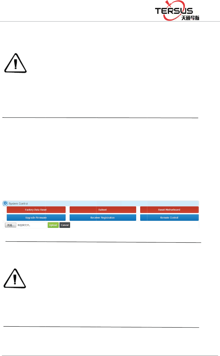
5RRP
4.10
F
Web
p
In the
W
-ǏSy
s
shown
U dis
k
%XLOGLQJ/DQH
ab
n
2,
I
b
y
lo
g
co
r
3,
p
4,
co
n
cl
o
re
b
F
irmwa
r
p
a
g
e up
gr
W
EB ma
n
s
tem cont
r
in Figur
e
Noti
c
1.up
d
(wit
h
or u
p
2.up
l
upgr
a
3.the
envi
r
k
up
g
rad
e
=KDQJKHQ
J
n
ormal;
I
n FTP s
e
date is f
o
g
is the s
y
r
respondi
n
p
rohibit o
f
downloa
d
n
nection
s
o
se the p
a
b
oot the d
e
r
e upgr
a
r
ade firm
w
n
agement
r
olǐclic
k
e
4-24
F
c
e:
d
ate the f
i
h
out the
q
p
grade the
l
oad fi
r
m
w
a
de the fi
r
time of
u
r
onment,
l
e
firmwa
r
J
5RDG3XGRQJ
e
rver loca
o
r the rec
e
y
stem log
n
g file; lo
s
f
use dow
d
time is
r
s
peed, pl
e
a
ge and
b
e
vice.
a
de
w
are
system s
e
k
ǏUpgr
a
F
igure 4-
2
i
rmware
p
q
uotation
m
firmwar
e
w
are pac
k
r
mware fa
u
ploading
t
l
ong pass
u
r
e
'LVWULFW6KDQJK
D
l (interna
l
e
iver to c
o
folder; m
a
s
t + foun
d
nload too
l
r
elated to
e
ase be p
a
b
rowser,
e
lect Ǐa
d
a
de the fi
r
2
4 Firmw
a
p
ackage
w
m
arks). P
l
e
fails;
k
age, pl
e
ils.
t
he firm
w
u
nder LA
N
D
L
l
memory
o
llect the
a
il folder
d
Folder is
l
s to dow
n
the size
o
a
tient. W
h
do not d
i
d
vanced s
e
r
mwareǐ
a
re upgra
d
w
as name
d
l
ease do
n
e
ase do
n
w
are pack
a
N
is abou
t
) folder,
t
raw data
is
t
he ma
i
the syste
m
n
load.
o
f file an
d
h
en down
l
i
sconnect
e
ttingsǐ-
Expand t
h
d
e
d
"Matrix
R
n
ot modi
fy
n
ot close
a
ge relate
d
t
10 seco
n
t
he folder
and Rin
e
i
lbox rec
e
m
folder;
d
your ne
l
oading,
y
the net
w
ǏHost s
e
h
e dialog
R
T
K
Upd
a
fy
this fil
e
the bro
w
d
to your
n
n
ds.
named
e
x data;
e
ive the
twork's
y
ou can
w
ork or
e
ttingsǐ
box as
a
te.bin"
e
name,
w
ser, or
n
etwork
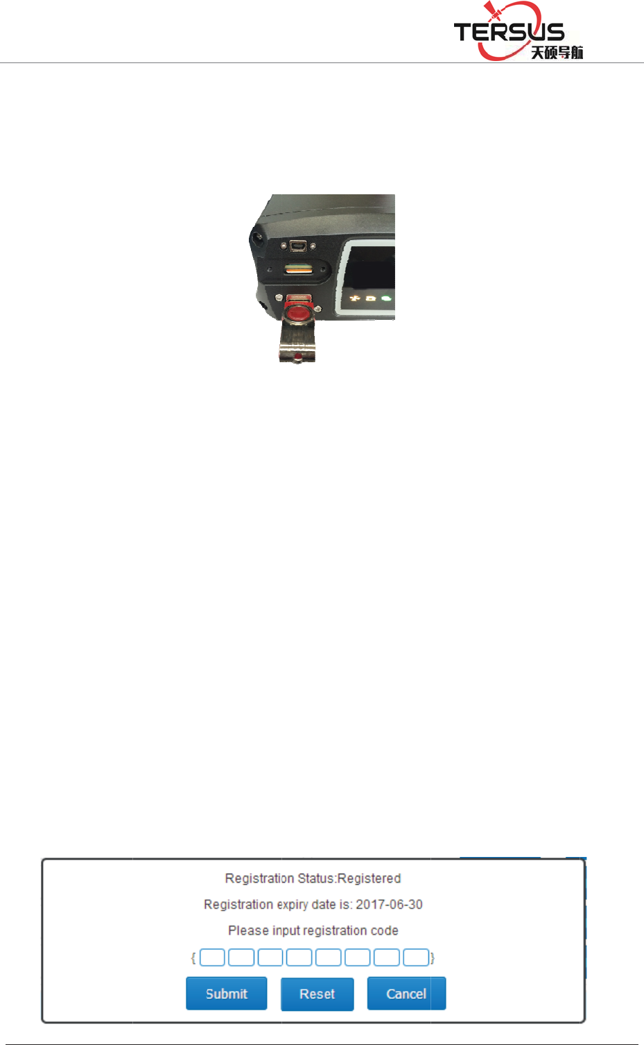
5RRP
Firstly
,
upgra
d
port at
In the
"Powe
after c
disk i
s
Ǐupg
r
restart
4.11
R
In the
W
-ǏSys
t
in Fig
u
%XLOGLQJ/DQH
,
copy th
e
d
ed to the
the front
LCD me
n
r button"
,
onfirmati
o
s
not inse
r
r
ade fir
m
that repr
e
R
egister
W
EB ma
n
t
em contr
o
u
re 4-26
=KDQJKHQ
J
e
firmwar
e
U disk ro
panel of t
h
Figu
r
n
u select
,
Pop-up
p
o
n, Click
r
ted iden
t
m
wareǐse
e
sents the
the rec
e
n
agement
o
lǐclick
Ǐ
J
5RDG3XGRQJ
e
packag
e
ot directo
r
h
e receiv
e
r
e 4-25 U
ǏSystem
p
rompt b
o
the "Pow
t
ify as err
lection i
n
success o
f
e
iver
system s
e
Ǐ
Receiver
'LVWULFW6KDQJK
D
e
"Matrix
R
r
y, and th
e
e
r; as sho
w
disk inst
a
settingsǐ
o
x "Pleas
er button
"
or, it wil
l
n
terface)
a
f
the upgr
a
e
lect Ǐa
d
registrati
o
D
L
R
T
K
_Up
d
e
n insert
t
w
n in Fig
u
a
llation di
a
-ǏUpg
r
e confir
m
"
prompt
s
l
prompt
"
a
bout 1
m
a
de.
d
vanced s
e
o
nǐExpa
n
d
ate.bin" t
h
t
he U dis
k
u
re 4-25:
a
gram
r
ade the f
i
m
the inse
s
ending s
u
"
no U di
s
m
inute la
e
ttingsǐ-
n
d the dia
l
h
at neede
k
into the
U
i
rmwareǐ
rtion of
U
u
ccessful
l
s
k" and r
e
a
ter, the
r
ǏHost s
e
l
og box a
s
d to be
U
AB-A
, click
U
disk"
l
y (if U
e
turn to
r
eceiver
e
ttingsǐ
s
shown

5RRP%XLOGLQJ/DQH=KDQJKHQJ5RDG3XGRQJ'LVWULFW6KDQJKDL
Figure 4-26 Receiver Registration
The receiver License format is 24 digits, divided into 8 groups, each group
contains 3. After entering the registration code just enter the registration code
(the system will ignore blanks of the registration code while entering), confirm it
and click Ǐsubmitǐ.
Diagnosis analysis and troubleshooting of common faults
5.1 The system starts normally, while lock star light SV is off
1.Check the environment of GNSS external antenna, GNSS external antenna
installation is downward, whether reference to the instructions in the overview
and precaution for distribution and installation;
2.Check the registration code is expired or not, such as the validity of WEB
management system and if the body number become red, means the registration
code has expired, please contact related staff of Tersus to apply for registration
code, and log MatrixRTK series Web management system registered receiver;
3.Check the GNSS antenna cable at both ends and check the connection between
GNSS receiver and GNSS antenna is tight or not, if loose please tighten, and
wait for about 30 seconds;
4. Monitor whether the GNSS antenna cable is connected to the GNSS ANT port,
not the WIFI ANT port.
5.2 The GNSS receiver is working properly and the terminal software has been
deployed, but the network transmission status is connecting

5RRP%XLOGLQJ/DQH=KDQJKHQJ5RDG3XGRQJ'LVWULFW6KDQJKDL
1.Check the connected network mode, network protocol and IP address and port
is correct;
2.Such as the network mode for the 3G, check the network parameters of the 3G
network is open; and make sure the local network environment is right, you can
use your mobile phone to check it. Make sure the SIM card is Unicom 3G / 2G
or mobile 2G card, and the data traffic is normal, that is activated and no arrears.
5.3. GNSS receiver is working properly, network transmission is connected, but
the raw data output frequency is incorrect
Use the network debugging assistant to receive data to check the data output
frequency is correct or not, such as the output frequency is less than the seted
frequencyˈmake sure whether to open a record of a data record, and record the
frequency is greater than or equal to the network transmission of raw data
frequency, and open the automatic removal function.
Establish several data records, at the beginning the recording is normal, but
become not normal later
1. The late record is intermittent; make sure whether the power supply is normal,
if the battery is 12V power supply, the battery voltage should not less than
10.5V; if use switching power supply , make sure the output power is greater
than 15W.
2. No record later; check whether the registration is expired, if not, check
whether the GNSS receiver lock satellites, if so check the space of storage
capacity.

5RRP%XLOGLQJ/DQH=KDQJKHQJ5RDG3XGRQJ'LVWULFW6KDQJKDL
5.4 Network cable connection is normal, but can not log on and visit the VNet
series (ground enhancement) Web management system;
1.Make sure whether the computer settings are set according to the network
settings and wired network settings in the manual.
2. The computer can ping the GNSS receiver, but can not access; turn off the
firewall and anti-virus software.
3.Make sure the IP inputted is correct. If can't just double-click the [power
button] to see the current IP address.

5RRP%XLOGLQJ/DQH=KDQJKHQJ5RDG3XGRQJ'LVWULFW6KDQJKDL
Chapter5Appendix
5.1 Reset
Major items content The parameters after recovery
Reference station
Site name HI-TAGET High precision GNSS receiver
UTC Time zone UTC+8
Antenna attenuation
[dB]
5
Antenna model AT-1200B
Antenna high [m] 0
Reference station
work mode
Rover
Ephemeris interval Every 30min
Correction data format RTCMV3
Satellite system All open
Height cutoff angle 10°
Receiver function
Storage device Internal storage
2G/3G internet OFF
RS232/RS485 Serial
port
OFF
Server port settings 80
Firewall OFF
Time input OFF
External clock input OFF
PPS output OFF
FTPPush OFF
User Only retain administrator privileges, and
restore the default password
Automatic cleaning
time after full
1 day
Small five-core serial
port pointing
Motherboard 1COM2
Power output OFF
Data
management
Network transmission Delete all
Data record Delete all
Internal data Delete all
Log management Delete all

5RRP%XLOGLQJ/DQH=KDQJKHQJ5RDG3XGRQJ'LVWULFW6KDQJKDL
5.2 MatrixRTK technical performance parameters table
Model MatrixRTK
GNSS
characte-ri
stic
Number of channels˖220
GPS˖L1ǃL2ǃL5
GLONASS: L1ǃL2
BDS:B1ǃB2
GALILEO:L1BOC,E5A,
E5B,E5AltBOC
SBAS:L1C/A,L5
positioning accuracy
RTK Horizontal accuracy˖±(8mm+1X10⁻⁶D)
RTK Vertical accuracy˖±(15mm+1X10⁻⁶D)
Static Horizontal accuracy˖±(2.5mm+1X10⁻⁶D)
Static vertical precision˖±(5.0mm+1X10⁻⁶D)
Initialization time typical <10S
Initialize reliability ˚99.9%
Port
3 RS232 port
1 USB port
1 WiFiǃBluetooth communication port
1 3G/2G Communication port
1 RS485/RS422 port
1 Ethernet interface
1 External clock interface
1 PPS Output Interface
Internal
storage 64GB
External
storage Maximum support is not less than 1TB
Correction
data
format
CMRǃRTCM2.xǃRTCM3.0ǃRTCM3.2
Human-co
mputer
interactio-
n
WEB Web management system
LCDǃIndicator, button operating system
Battery
External power supply˖7VDC~36VDC˄2˅
Built-in battery˖24h Continuous work (related to configuration)
Power consumption: 5W
Environm-
ental
adaptabi-li
ty
Working temperature -40ć̚75ć
storage temperature -40ć̚80ć
Relative humidity 100%
Protection class IP67

5RRP%XLOGLQJ/DQH=KDQJKHQJ5RDG3XGRQJ'LVWULFW6KDQJKDL
Anti-corrosion Satisfy GJB150.11
vibration Satisfy GJB_1032
Impact Satisfy JB/T 9329 30g 3 Times / axis
collision Satisfy JB/T 9329 10g 1000 Times
Drop Satisfy GB-T2423.8 protect from 1 meter’s drop
5.3 Standard configuration table
Item Name Number
GNSS Receiver 1
Power Adapter 1
AC power cord 1
Vnet Data cable 1
Direct cable 1
Vnet Packaging cartons 1
Vnet10 Packing lining 1
Ground reinforcement system product manual 1
Aluminum lugs 3
Cross plate head machine wire [M3*6] 3
Warranty Card 1
Factory inspection certificate 1
5.4 Obligations of importers
Importers shall indicate on the electrical equipment their name, registered
trade name or registered trade mark and the postal address at which they can be
contacted or, where that is not possible, on its packaging or in a document
accompanying the electrical equipment. The contact details shall be in a
language easily understood by endusers and market surveillance authorities.

5RRP%XLOGLQJ/DQH=KDQJKHQJ5RDG3XGRQJ'LVWULFW6KDQJKDL
5.5 Caution
RISK OF EXPLOSION IF BATTERY IS REPLACEDBY AN
INCORRECT TYPE DISPOSE OF USED BATTERIES ACCORDING TO
THE INSTRUCTIONS

5RRP%XLOGLQJ/DQH=KDQJKHQJ5RDG3XGRQJ'LVWULFW6KDQJKDL
§ 15.19 Labelling requirements.
This device complies with part 15 of the FCC Rules. Operation is subject to
the condition that this device does not cause harmful interference.
§ 15.21 Information to user.
Any Changes or modifications not expressly approved by the party responsible
for compliance could void the user's authority to operate the equipment.
§ 15.105 Information to the user.
Note: This equipment has been tested and found to comply with the limits for
a Class B digital device, pursuant to part 15 of the FCC Rules. These limits are
designed to provide reasonable protection against harmful interference in a
residential installation. This equipment generates uses and can radiate radio
frequency energy and, if not installed and used in accordance with the
instructions, may cause harmful interference to radio communications.
However, there is no guarantee that interference will not occur in a particular
installation. If this equipment does cause harmful interference to radio or
television reception, which can be determined by turning the equipment off
and on, the user is encouraged to try to correct the interference by one or more
of the following measures:
-Reorient or relocate the receiving antenna.
-Increase the separation between the equipment and receiver.
-Connect the equipment into an outlet on a circuit different from that to which
the receiver is connected.
-Consult the dealer or an experienced radio/TV technician for help.
*RF warning for Mobile device:
This equipment complies with FCC radiation exposure limits set forth for an
uncontrolled environment. This equipment should be installed and operated wi
th minimum distance 30cm between the radiator & your body.