Tersus GNSS RS460 David 2W Radio User Manual user manual
Tersus GNSS Inc. David 2W Radio user manual
user_manual
User Manual
Version V1.0-20180525
Sales & Technical Support:
sales@tersus-gnss.com & support@tersus-gnss.com
More details, please visit www.tersus-gnss.com
User Manual
For David GNSS Receiver
©2018 Tersus GNSS Inc. All rights reserved.
1 / 76
Table of Content
1. Overview ....................................................................................................................8
1.1 Introduction ............................................................................................................... 8
1.2 Receiver Features ....................................................................................................... 8
1.3 Brief Introduction of GNSS and RTK ........................................................................... 9
2. Devices in David Package ................................................................................... 11
2.1 Rove Kit Mobile Mode ................................................................................................... 12
2.1.1 David Receiver ............................................................................................... 14
2.1.2 GNSS Antenna ............................................................................................... 14
2.1.3 The 2pin-USB Power Cable ......................................................................... 15
2.1.4 COMM1-bluetooth Module ........................................................................... 16
2.1.5 Bracket for Rover ........................................................................................... 16
2.1.6 GNSS Antenna Connector ........................................................................... 17
2.1.7 COMM2-7pin-USB & DB9 Data Cable ....................................................... 17
2.1.8 Other accessories .......................................................................................... 18
2.2 Rover Kit with 1W Radio Station .............................................................................. 20
2.2.1 RS900C 1W/915MHz Radio ........................................................................ 22
2.3 Rover Kit with 2W Radio Station .............................................................................. 22
2.3.1 RS400L2 2W/460MHz Radio ....................................................................... 24
2.3.2 COMM2-7pin-USB & 5pin Cable ................................................................. 26
2.4 Base Kit Mobile Mode .............................................................................................. 26
2.4.1 Bracket for Base ............................................................................................. 28
2.4.2 Tape Meter ...................................................................................................... 28
2.5 Base Kit with 1W Radio Station ................................................................................ 29
2.6 Base Kit with 2W Radio Station ................................................................................ 30
2.7 Base Kit with 30W Radio Station .............................................................................. 31
2.7.1 30W Radio ...................................................................................................... 33
2.7.2 Other cables ................................................................................................... 34
3. General operation .................................................................................................. 36
3.1 Install the GNSS antenna ............................................................................................... 36
3.2 Power on David ............................................................................................................. 36
2 / 76
3.3 Communication between Android phone and David .................................................... 37
3.3.1 With Wires ....................................................................................................... 38
3.3.2 With an External Bluetooth ........................................................................... 40
3.4 FW Upgrade & Auth code .............................................................................................. 41
3.4.1 Firmware Updates .............................................................................................. 42
3.4.2 Auth Code ............................................................................................................ 45
3.5 Download Files from Internal eMMC Card .................................................................... 46
3.6 Input command directly to the GNSS board ............................................................ 49
4. Introduction of Nuwa® ........................................................................................... 51
5. Specification ........................................................................................................... 53
5.1 David Receiver ............................................................................................................... 53
5.2 ANTENNA AX3702 (HG) ................................................................................................. 56
5.3 1W Radio RS900C .......................................................................................................... 57
5.4 2W Radio RS400L2 ......................................................................................................... 59
5.5 30W Radio RS400L30 ..................................................................................................... 61
6. Typical operating ...................................................................................................... 64
6.1 David as a Rover to receive corrections from Internet ............................................ 64
6.2 David as a Base to transmit corrections to Internet ................................................ 67
6.3 Radios Transmit RTK Corrections between Two Davids .......................................... 70
6.4 Data Collection for Post Processing ......................................................................... 72
7. Terminology ............................................................................................................. 75
3 / 76
List of Figures
Figure 1 Outlook of David GNSS receiver .......................................................................... 8
Figure 2 Outline of David System ........................................................................................ 9
Figure 3 Corrections transmitted via Internet ................................................................... 10
Figure 4 Corrections transmitted with radios.................................................................... 10
Figure 5 David in the box .................................................................................................... 11
Figure 6 Field photo 1 - 1 .................................................................................................... 12
Figure 7 Field photo 1 - 2 .................................................................................................... 13
Figure 8 David Receiver ...................................................................................................... 14
Figure 9 AX3702 (HG) antenna .......................................................................................... 15
Figure 10 RF cable ............................................................................................................... 15
Figure 11 2pin-USB Power Cable ...................................................................................... 16
Figure 12 Bluetooth Module ................................................................................................ 16
Figure 13 Bracket for Rover ................................................................................................ 17
Figure 14 GNSS Antenna Connector ................................................................................ 17
Figure 15 COMM2-7pin-USB & DB9 Data Cable ............................................................ 18
Figure 16 USB Type A Male to DB9 Male cable .............................................................. 18
Figure 17 USB Type A Male to USB Type A Male cable ................................................. 19
Figure 18 USB Type A Female to USB (Micro + Type C) OTG cable .......................... 19
Figure 19 Height Measure Accessory ............................................................................... 19
Figure 20 Battery Bank ........................................................................................................ 20
Figure 21 Field Photo 2 - 1 ................................................................................................. 20
Figure 22 Field Photo 2-2 .................................................................................................... 21
Figure 23 RS900C 1W Radio Station ............................................................................... 22
Figure 24 Field Photo 3 - 1 ................................................................................................. 23
Figure 25 Field Photo 3 - 2 ................................................................................................. 23
Figure 26 2W /460MHz Radio ............................................................................................ 25
Figure 27 COMM2-7pin-USB & 5pin Cable...................................................................... 26
Figure 28 Field Photo 4 ....................................................................................................... 27
Figure 29 Bracket for Base ................................................................................................. 28
Figure 30 Tape Meter ........................................................................................................... 29
Figure 31 Field Photo 5 ....................................................................................................... 29
Figure 32 Field Photo 7 - 1 ................................................................................................. 31
Figure 33 Field Photo 7 - 2 ................................................................................................. 32
Figure 34 30W Radio Station ............................................................................................. 33
Figure 35 Power cable for 30W radio ................................................................................ 34
Figure 36 COMM cable for 30W radio .............................................................................. 35
Figure 37 David GNSS receiver installation hook ........................................................... 35
Figure 38 Outline of Android phone to David with Wires ............................................... 38
Figure 39 Outline of Android phone to David with Bluetooth ......................................... 40
Figure 40 Outline of David connected to a Computer .................................................... 41
Figure 41 Download file from eMMC card ........................................................................ 46
Figure 42 Booting up page .................................................................................................. 51
Figure 43 Four Main Windows of Nuwa ............................................................................ 52
4 / 76
Figure 44 Panel of David ..................................................................................................... 54
Figure 45 Pin Definition of the COMM1/COMM2/DC ports ........................................... 55
Figure 46 Outline of Android phone to David with Wire ................................................. 65
Figure 47 Outline of Android phone to David with Wire ................................................. 67
Figure 48 Outline of Base/Rover with Radios .................................................................. 70
Figure 49 Outline of Static Data Collection ...................................................................... 73
5 / 76
List of Tables
Table 1 The document / software used in this user manual ............................................. 6
Table 2 Seven David Variants ............................................................................................. 11
Table 3 Devices in rover mobile mode .............................................................................. 13
Table 4 Definition of LEDs ................................................................................................... 14
Table 5 Functions of COMM2-7pin-USB & DB9 Data Cable ......................................... 18
Table 6 Rover Kit with 1W Radio Station .......................................................................... 21
Table 7 LED Definition ......................................................................................................... 22
Table 8 Rover Kit with 2W Radio Station .......................................................................... 24
Table 9 Button Manual ......................................................................................................... 25
Table 10 LED Definition ....................................................................................................... 26
Table 11 Base Kit Mobile Mode .......................................................................................... 27
Table 12 Base Kit with 1W Radio Station ......................................................................... 30
Table 13 Base Kit with 30W Radio Station ....................................................................... 32
Table 14 The Definition of the Control Buttons ................................................................ 33
Table 15 Definition of LEDs ................................................................................................ 34
Table 16 Detailed steps ....................................................................................................... 39
Table 17 Detailed steps ....................................................................................................... 40
Table 18 Preparation for FW update ................................................................................. 42
Table 19 Detailed Steps for FW update ............................................................................ 43
Table 20 Detailed Steps to download files from eMMC card......................................... 46
Table 21 Input commands to the BX306 directly ............................................................. 49
Table 22 David GNSS Performance .................................................................................. 53
Table 23 Pin Definition ........................................................................................................ 55
Table 24 Antenna AX3702 (HG) ......................................................................................... 56
Table 25 Specification for RS900C .................................................................................... 57
Table 26 Specification for RS400L2 .................................................................................. 59
Table 27 RS400L30 Radio Specification .......................................................................... 61
Table 28 Detailed steps for rover receive corrections from Internet ............................. 65
Table 29 Detailed steps for Base transmit corrections to Internet ................................ 68
Table 30 Detailed steps for David with Radios ................................................................ 70
Table 31 Detailed Steps for Static Data Collection .......................................................... 73
Table 32 List of terminology ................................................................................................ 75
6 / 76
Notices
The following notices apply to DAVID receiver.
Changes or modifications to this equipment not expressly approved by
Tersus could void the user‟s authority to operate this equipment or
even has risk to damage the DAVID.
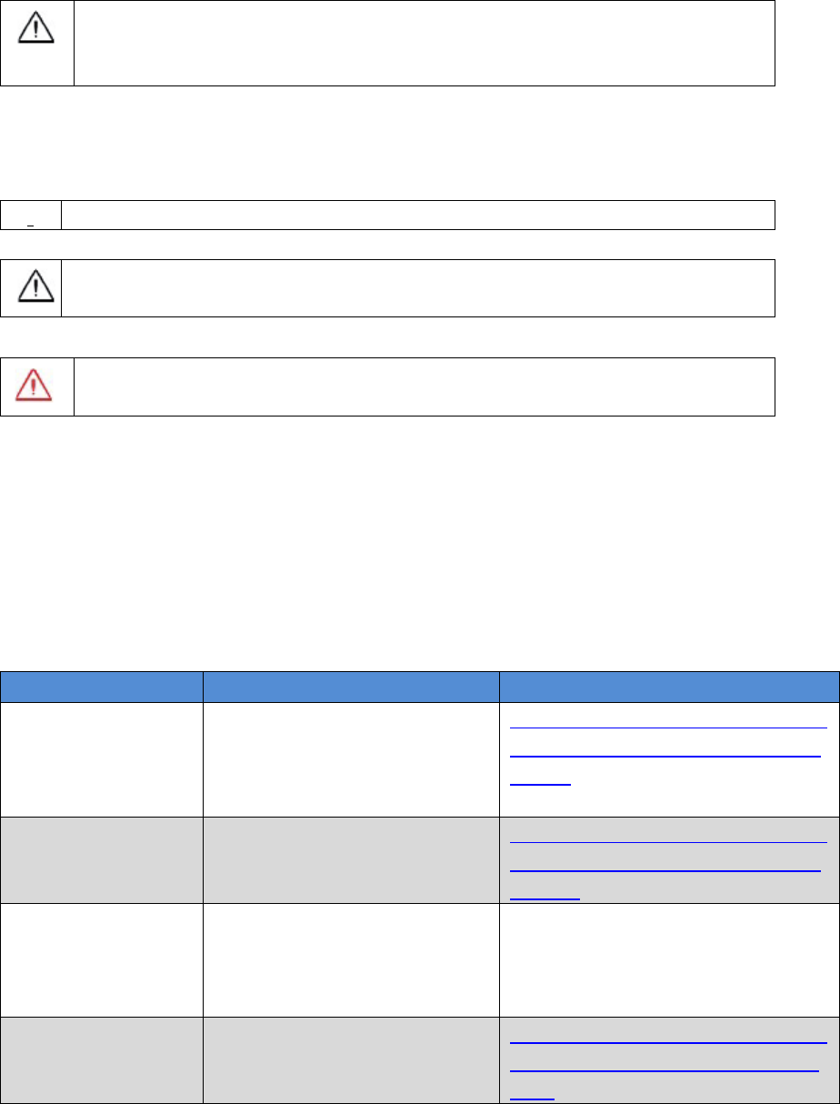
Conventions
The following conventions are used in this manual:
!
Information that supplements or clarifies text.
A caution that actions, operation or configuration may lead to incorrect
or improper use of the hardware.
NUWA is Tersus survey app, four tabs (Project, Device, Survey and Tools) are
provided in the Nuwa® main window. So, in chapter 0, all the operations in the
Survey software will start from these four tabs.
In all the figures, a line with two arrows at the two sides means it‟s a cable. A
line with one arrow gives the installation direction.
Table 1 The document / software used in this user manual
Name
Description
Link
Log & Command
document
Document giving all the
loggings output from David
and all the commands to
David
https://www.tersus-gnss.com/ass
ets/upload/file/20180420120508
17.pdf
Tersus GNSS
Center
Graphical tool to
communicate with David
https://www.tersus-gnss.com/ass
ets/upload/file/20180418153351
742.zip
Nuwa
Survey application running
in the Android platform,
David can be configured
with Nuwa.
Tersus Geomatics
Office
Post processing tool for
static data
https://www.tersus-gnss.com/ass
ets/upload/file/20180418153011
5.rar
A warning that actions, operation or configuration may result in
regulatory noncompliance, safety issues or equipment damage.

8 / 76
1. Overview
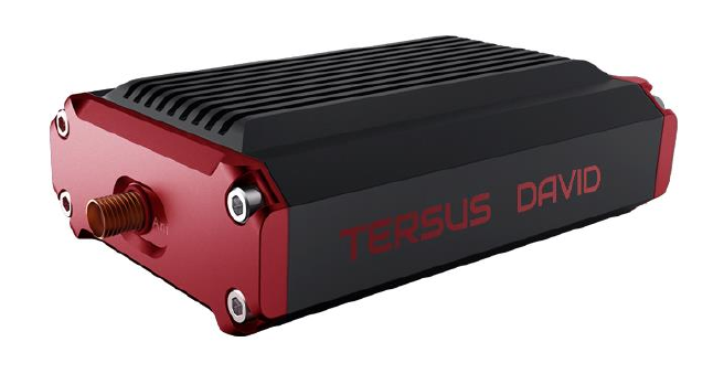
1.1 Introduction
Tersus DAVID is a cost-efficient, palm-sized GNSS receiver, mainly for the
mass survey market, but also for UAV/AGV/Agriculture application.
Nuwa, a survey App on Android system, is working with David, which can
communicate with an Android platform such as a phone or tablet via USB
cable or an external Bluetooth module. The David can work as a base or a
rover, it can support real-time RTK positioning as well as saving data for PPK
application. Up to 4GB on-board EMMC card makes it easy to save data for
PPK.
The RS-232 serial port, IP67 standard and the external Bluetooth module can
remove most of the inconvenience for field workers. All the operating can be
done in the App Nuwa except downloading raw measurement data file, which
will be done with Tersus GNSS Center, see Table 1 and section 3.5 Download
Files from Internal eMMC Card for detail.
Figure 1 Outlook of David GNSS receiver
1.2 Receiver Features
Supports GPS L1/L2, BDS B1/B2 and GLONASS G1/G2.
Support RTCM2.3/3.x, CMR, CMR+ corrections.
9 / 76
Easy to connect an external powerful radio for longer range.
Solution rate can be 5Hz.
20Hz raw measurements output for post processing.
The accuracy of carrier phase can be 1mm.
On-board 4GB eMMC card for data collection
Static post-processing for mm-level accuracy.
Bluetooth module makes wireless connection.
Input power range is 5 - 12V, connect to battery bank directly.
IP67 for water & dust proof, work reliably in harsh condition
The Lemo connectors support mis-installation avoidance.
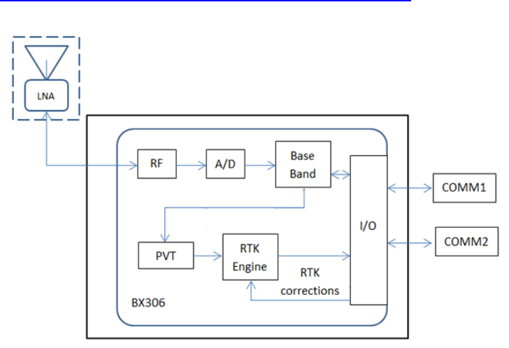
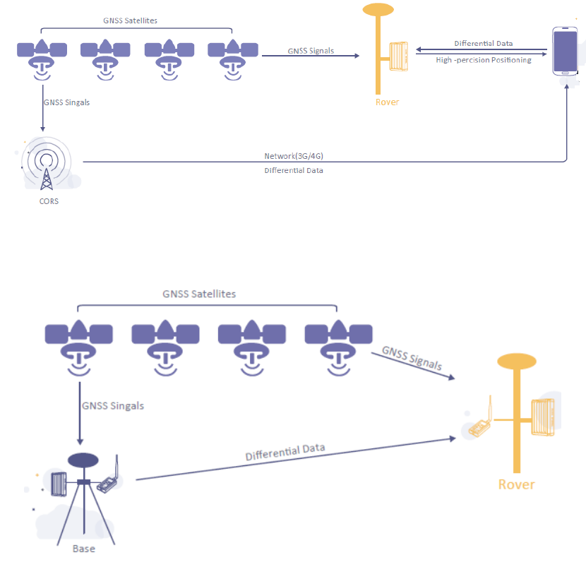
1.3 Brief Introduction of GNSS and RTK
Tersus BX306 GNSS receiver is integrated in David, the board is receiving the
GNSS signals from satellites and RTK corrections from the base, and is
outputting cm-level position, velocity and time. Figure 2 shows David system;
see https://www.tersus-gnss.com/product/bx306-oem-board for more about
BX306 receiver.
Figure 2 Outline of David System
10 / 76
The RTK corrections are transmitted from a base, which can be a CORS
station or a David receiver. The RTK corrections can be transmitted to the
rover via Internet or with external radios.
Figure 3 Corrections transmitted via Internet
Figure 4 Corrections transmitted with radios
If RTK corrections are transmitted via Internet, an Android phone will be
included in the RTK system to transmit/receive the RTK corrections, see
section 6.1 and section 6.2 for detailed operating.
11 / 76
2. Devices in David Package
This chapter will give detailed introduction about all the devices in the
package.
David has seven variants, which are convenient for customers to select per
their application. Different accessories are included in each variant. Table 2
gives a brief description of the seven variants. For more about them, refer to
section 2.1 to section 2.7.
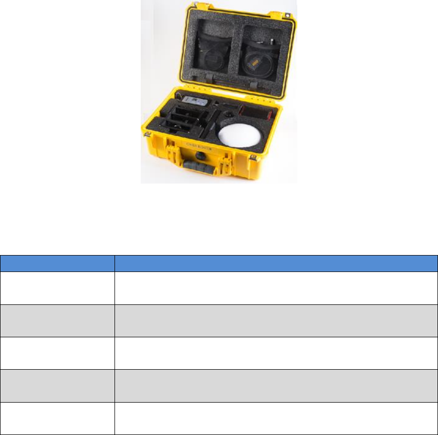
All the seven variants are shipped in a plastic box in Figure 5.
Figure 5 David in the box
Table 2 Seven David Variants
David variants
Description
Rover Kit Mobile
Mode
The David receiver will receive RTK corrections from a
NTRIP caster or a TCP server.
Rover Kit with 1W
Radio Station
The David receiver will receive RTK corrections from an
external 1W 915Mhz radios.
Rover Kit with 2W
Radio Station
The David receiver will receive RTK corrections from an
external 2W 460MHz radios.
Base Kit Mobile
Mode
The David receiver will output RTK corrections to a
NTRIP caster or a TCP server.
Base Kit with 1W
Radio Station
The David receiver will output RTK corrections to an
external 1W 915Mhz radio.
12 / 76
Base Kit with 2W
Radio Station
The David receiver will output RTK corrections to an
external 2W 460MHz radio.
Base Kit with 30W
Radio Station
The David receiver will output RTK corrections to an
external 30W 460MHz radio.
!
1. Rover Kit Mobile Mode and Base Kit Mobile Mode can work
independently.
2. Rover Kit with 1W Radio Station must work with Base Kit with 1W
Radio Station.
3. Rover Kit with 2W Radio Station must work with Base Kit with 2W
Radio Station or Base Kit with 30W Radio Station.
2.1 Rove Kit Mobile Mode
In this variant, the David will be connected to an Android phone with Bluetooth
module or with cables. Tersus Survey Nuwa® App will run in the Android phone
to receive RTK corrections from a NTRIP caster or a TCP server.
Refer to section 6.1 for detailed operation.
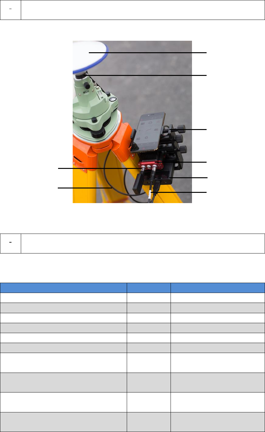
Figure 6 Field photo 1 - 1
1
2
3
13 / 76
Figure 7 Field photo 1 - 2
Table 3 Devices in rover mobile mode
Devices
Number
Items in the field photos
David GNSS receiver
1
5
GNSS antenna
1
1
GNSS antenna connector
1
Not in the field photo, refer
to section 2.1.6 for detail.
GNSS antenna cable
1
3
2pin-USB power cable
1
8
COMM1-bluetooth module
1
6, refer to 2.1.4
COMM2-7pin-USB & DB9 Data cable
1
Not in the field photo, refer
to section 2.1.7
USB Type A Male to USB Type A
Male cable
1
Not in the field photo, refer
to Figure 17
USB Type A Female to USB(Micro +
Type C) OTG cable
1
Not in the field photo, refer
to Figure 18
USB Type A Male to DB9 Male cable
1
Not in the field photo, refer
to Figure 16
Ranging pole
1
2
Height measure accessory
1
Not in the field photo, See
Figure 19.
Bracket for rover
1
4, see section 2.1.5
Battery bank
1
7, see Figure 20 and 3.2
Power on David
5
4
6
7
8
14 / 76
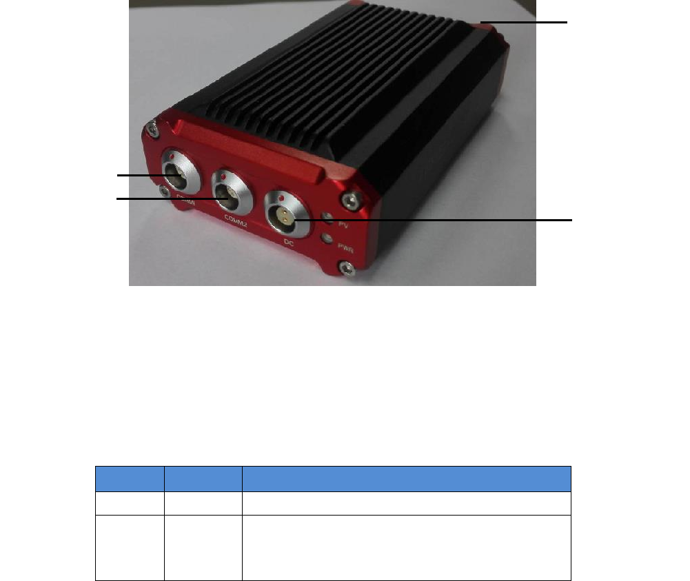
2.1.1 David Receiver
David has four interfaces, see Figure 8 David Receiver.
Figure 8 David Receiver
David‟s DC is for power input, COMM1 port is for COM1 and CAN ports, and
COMM2 port is for COM2 and USB ports, see chapter 5 for detail.
Table 4 Definition of LEDs
LED
Colour
Description
PWR
RED
ON: the David is power on.
PV
GREEN
ON: David in RTK solution.
Blink: David in Float solution
OFF: David in other position types.
Please see section 3.2 Power on David for more about the booting up
procedure.
Refer to Chapter 5 for the specification of David receiver and the detailed
definition of COMM1, COMM2 and DC ports.
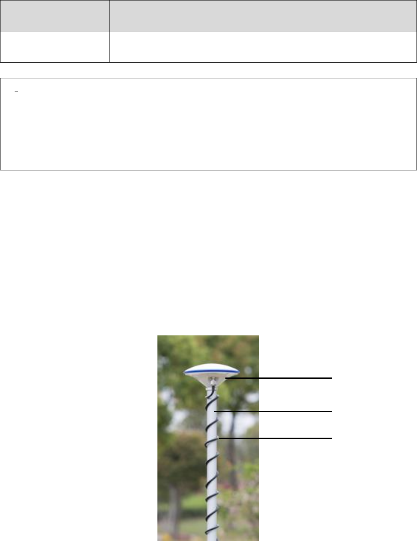
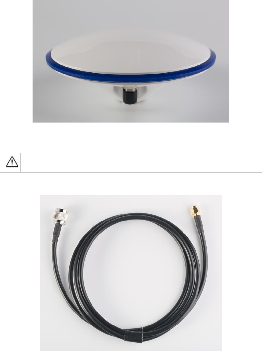
2.1.2 GNSS Antenna
GNSS antenna is used to receive the RF signal from the satellites. AX3702
(HG) is provided in the package, which must be connected to the David with
the RF cable in the package.
Antenna input
DC port
COMM1 port
COMM2 port
15 / 76
Figure 9 AX3702 (HG) antenna
If an antenna from other companies will be used, contact Tersus to get
permission, or the David may not work as it‟s expected.
Figure 10 RF cable
2.1.3 The 2pin-USB Power Cable
The power cable is used to connect a battery bank to the DC port of David.
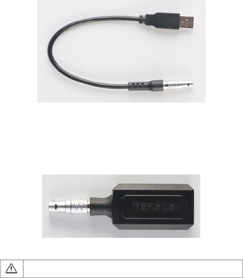
16 / 76
Figure 11 2pin-USB Power Cable
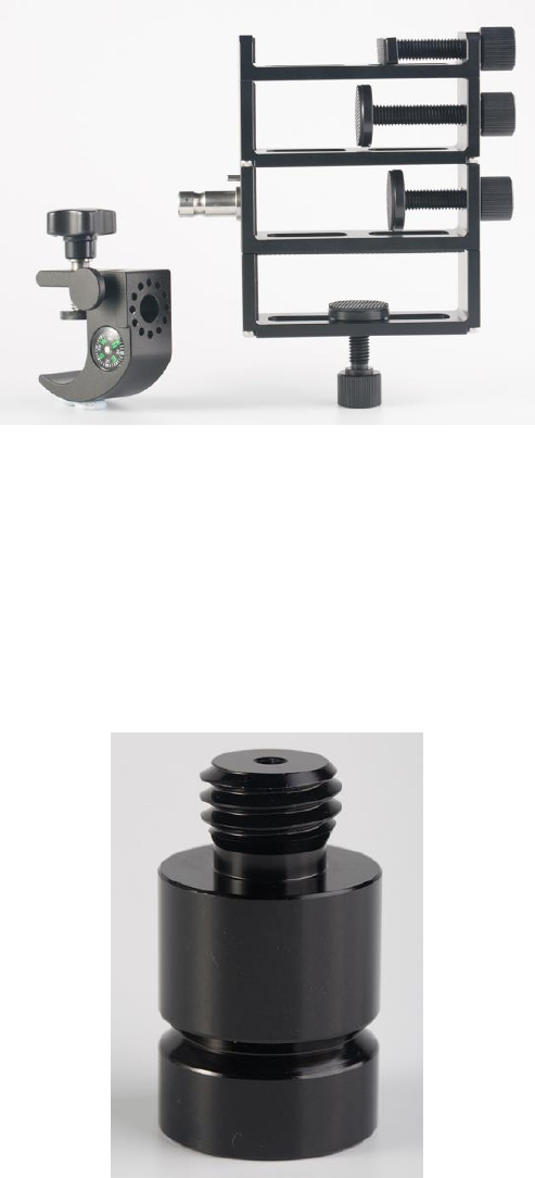
2.1.4 COMM1-bluetooth Module
This Bluetooth module will use the COM1 port of David.
Figure 12 Bluetooth Module
The Bluetooth can only be installed to the COMM1 port of David.
The SSID for this Bluetooth module is BT420A-xxxxx, where xxxxx is the last 5
digits of the Bluetooth serial number, which is printed on the Bluetooth module.
No password is needed to pair with it.
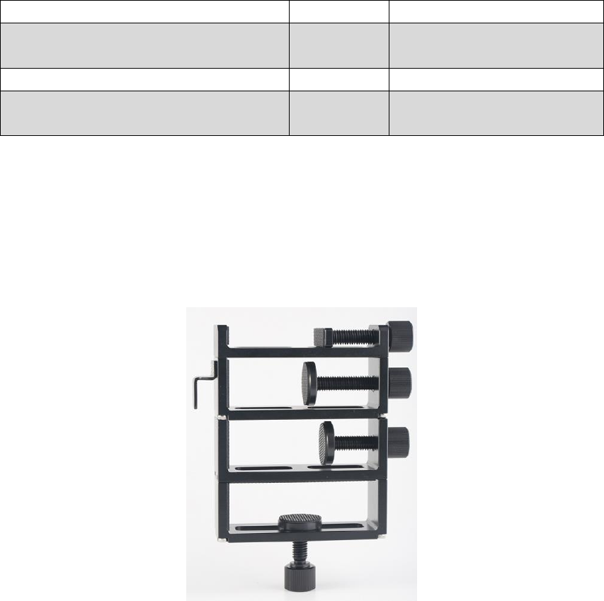
2.1.5 Bracket for Rover
Bracket for rover is used to fix all the devices on the ranging pole, which bring
much convenience to field staffs.
17 / 76
Figure 13 Bracket for Rover
2.1.6 GNSS Antenna Connector
The GNSS antenna connector is used to install the GNSS antenna or the 30W
radio station antenna to a tripod.
Figure 14 GNSS Antenna Connector
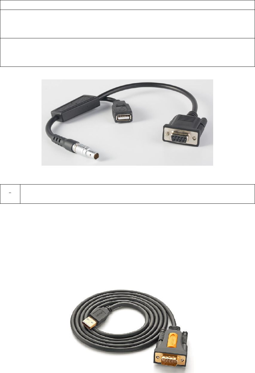
2.1.7 COMM2-7pin-USB & DB9 Data Cable
The COMM2-7pin-USB & DB9 Data Cable has three functions:
18 / 76
Table 5 Functions of COMM2-7pin-USB & DB9 Data Cable
1. Connect to an external 1W radio module.
2. Connect to USB Type A Male to DB9 Male cable (see Figure 16) to
download file saved on the internal eMMC card, refer to section 3.5
Download Files from Internal eMMC Card;
3. Connect to USB Type A Male to USB Type A Male cable (see Figure 17)
and USB Type A Female to USB (Micro +Type C) OTG cable (see Figure
18) to connect the Android phone with David, refer to section 3.3.1.
Figure 15 COMM2-7pin-USB & DB9 Data Cable
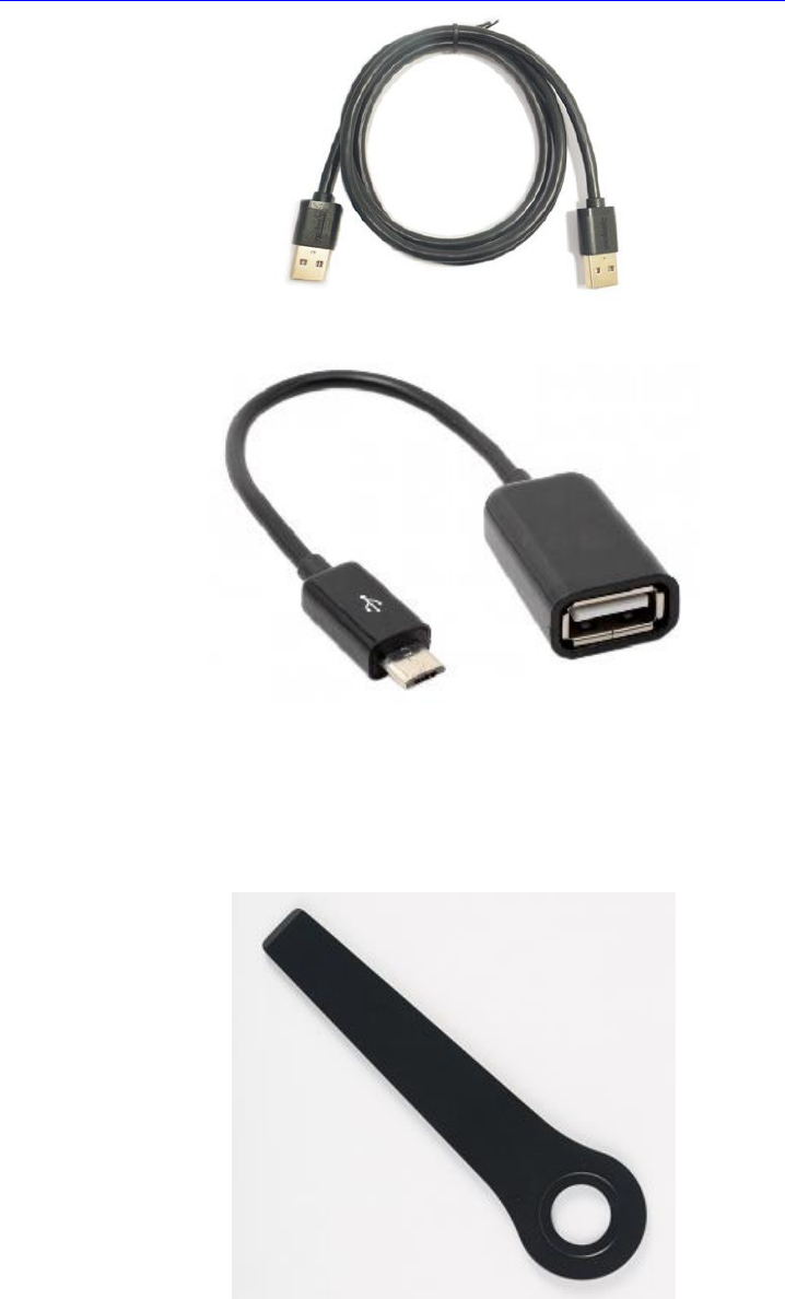
2.1.8 Other accessories
USB Type A Male to DB9 Male cable, USB Type A Male to USB Type A Male
cable, USB Type A Female to USB (Micro + Type C) OTG cable and Height
Measure Accessory are included in this variant.
Figure 16 USB Type A Male to DB9 Male cable
The driver for the cable above can be downloaded
!
The COMM2-7pin-USB cable can only be installed into the COMM2 port
of David.
19 / 76
https://www.ugreen.com/drivers/list-USB_To_RS232_Driver-en.html
Figure 17 USB Type A Male to USB Type A Male cable
Figure 18 USB Type A Female to USB (Micro + Type C) OTG cable
The height measure accessory is used to determine the height of the antenna
with higher accuracy.
Figure 19 Height Measure Accessory
A battery bank is used to power on the David, it‟s not included in the package,
and has to be provided by the customers, see section 3.2 Power on David for
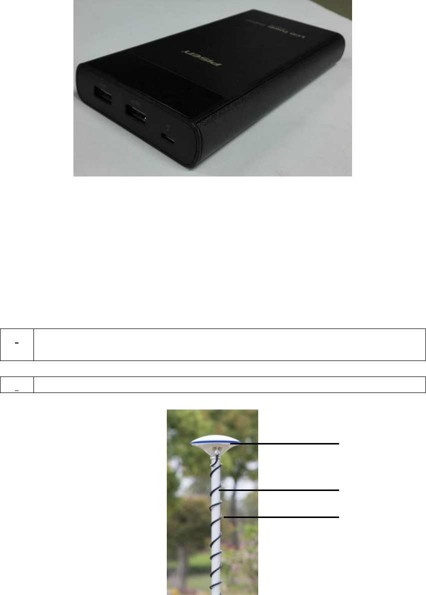
20 / 76
more detail.
Figure 20 Battery Bank
2.2 Rover Kit with 1W Radio Station
In this variant, the David will be connected to an external 1W radio to receive
RTK corrections from a base. With an external Bluetooth or with cables, the
David will be connected to an Android phone, which is running Tersus Survey
Nuwa® to configure the David.
!
Rover Kit with 1W Radio Station must work with Base Kit with 1W Radio
Station.
!
Rover Kit with 1W Radio Station can support Rover mobile mode.
Figure 21 Field Photo 2 - 1
1
2
3
21 / 76
Figure 22 Field Photo 2-2
Table 6 Rover Kit with 1W Radio Station
Devices
Number
Items in the field photos
David GNSS receiver
1
7
GNSS antenna
1
1
GNSS antenna connector
1
Not in the field photo, refer
to section 2.1.6 for detail.
GNSS antenna cable
1
3
2pin-USB power cable
1
8
COMM1-Bluetooth module
1
10, refer to 2.1.4.
COMM2-7pin-USB & DB9 data cable
1
11, refer to section 2.1.7.
USB Type A Male to USB Type A Male
cable
1
Not in the field photo, refer
to Figure 17
USB Type A Female to USB(Micro +
Type C) OTG cable
1
Not in the field photo, refer
to Figure 18
USB Type A Male to DB9 Male cable
1
Not in the field photo, refer
to Figure 16
RS900C 1W/915MHz radio
1
5, refer to section 2.2.1.
RS900C radio antenna
1
4
Ranging pole
1
2
Height measure accessory
1
Not in the field photo, See
Figure 19.
Bracket for rover
1
6, see section 2.1.5
Battery bank
1
9, see Figure 20 and 3.2
Power on David
4
5
6
7
10
11
8
9
22 / 76
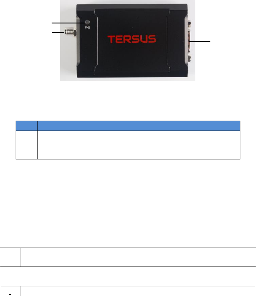
2.2.1 RS900C 1W/915MHz Radio
This radio can work at 915MHz frequency only, the output power of this radio is
1W and the typical range is 3km. Refer to chapter 5 for detailed specification.
Figure 23 RS900C 1W Radio Station
Table 7 LED Definition
LED
Description
P-S
When power on, this LED will blink RED once and keep off.
If data is transmitting, this LED will blink RED.
If data is receiving, this LED will blink GREEN.
2.3 Rover Kit with 2W Radio Station
In this variant, the David will be connected to an external 2W radio to receive
RTK corrections from a base. With an external Bluetooth or with cables, the
David will be connected to an Android phone, which is running Tersus Survey
Nuwa® to configure the David.
!
Rover Kit with 2W Radio Station can work with Base Kit with 2W Radio
Station or Base Kit with 30W Radio Station.
!
Rover Kit with 2W Radio Station can support Rover mobile mode.
Data
Interface
LED
Antenna
Interface
23 / 76
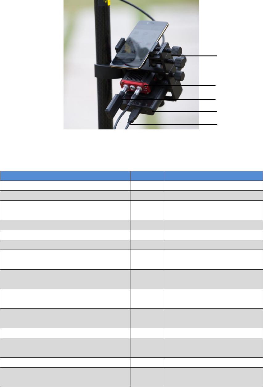
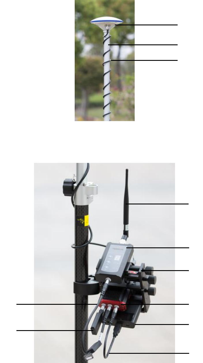
Figure 24 Field Photo 3 - 1
Figure 25 Field Photo 3 - 2
1
2
3
4
5
6
7
9
10
11
8

24 / 76
Table 8 Rover Kit with 2W Radio Station
David variants
Number
Items in field photos
David GNSS receiver
1
7
GNSS antenna
1
1
GNSS antenna connector
1
Not in the field photo,
refer to section 2.1.6 for
detail.
GNSS antenna cable
1
3
2 Pin-USB power cable
1
9
COMM1-bluetooth module
1
10, refer to 2.1.4
COMM2-7pin-USB & DB9 Data
cable
1
Not in the field photo,
refer to section 2.1.7.
USB Type A Male to USB Type
A Male cable
1
Not in the field photo,
refer to Figure 17
USB Type A Female to
USB(Micro + Type C) OTG
cable
1
Not in the field photo,
refer to Figure 18
USB Type A Male to DB9 Male
cable
1
Not in the field photo,
refer to Figure 16
COMM2-7pin-USB & 5pin cable
(0.35m)
11, refer to 2.3.2
RS400L2 2W/460MHz radio
1
5, refer to 2.3.1
2W/460MHz radio antenna
1
4
Ranging pole
1
2
Height measure accessory
1
Not in the field photo, See
Figure 19.
Bracket for rover
1
6, see section 2.1.5
Battery bank
1
8, see Figure 20 and 3.2
Power on David
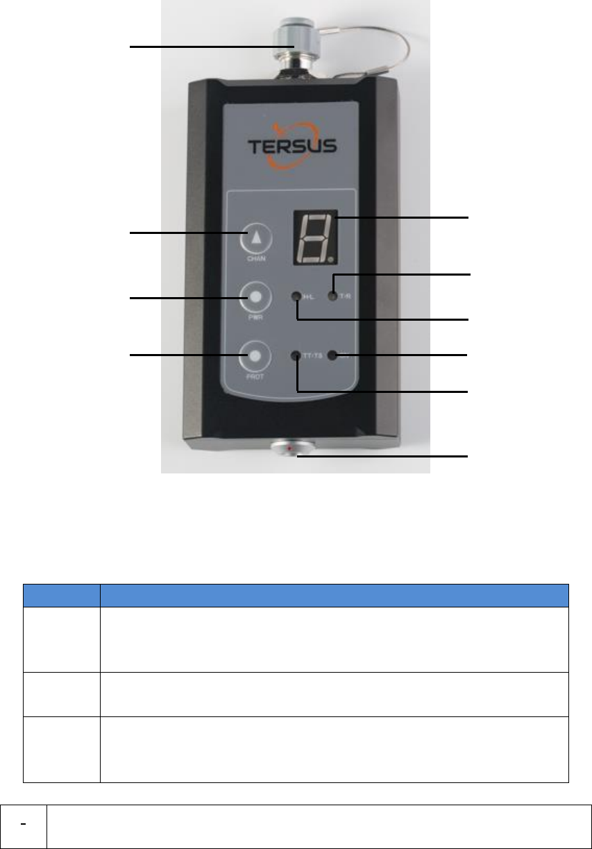
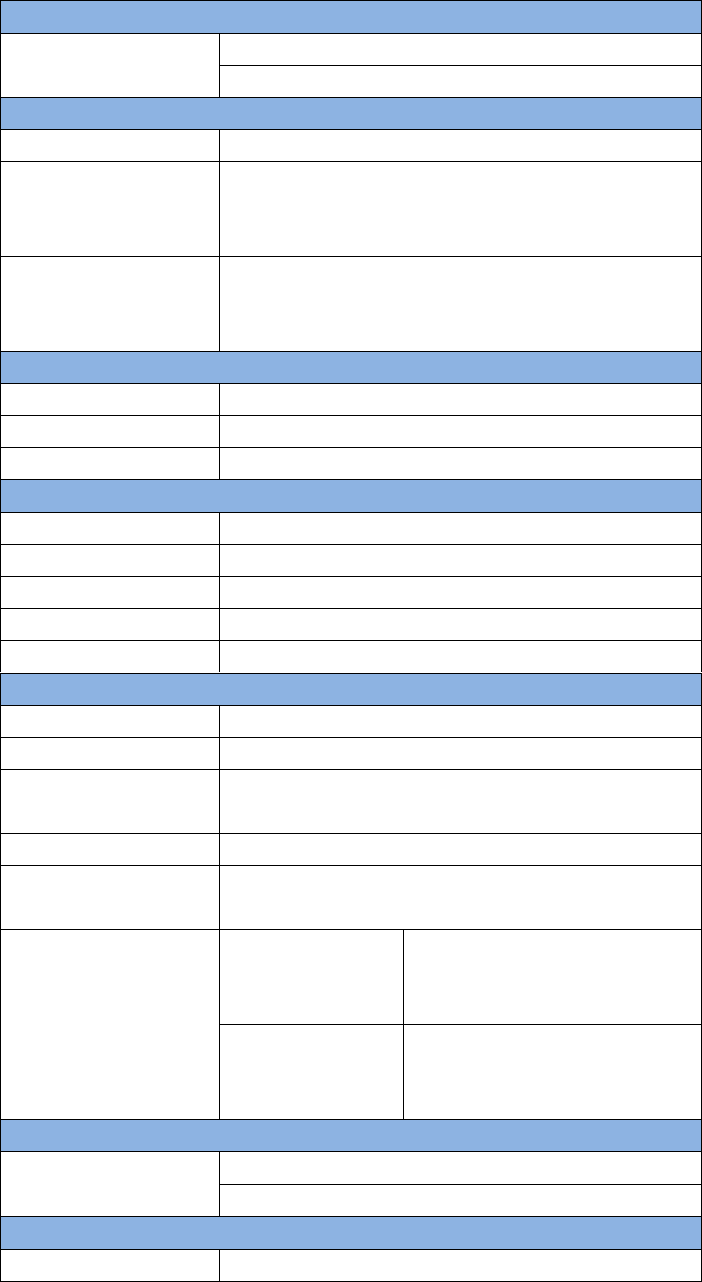
2.3.1 RS400L2 2W/460MHz Radio
This radio can work at 460MHz frequency, the max. output power of this radio
is 2W and the typical range is 5km. Refer to chapter 5 for detail specification.
25 / 76
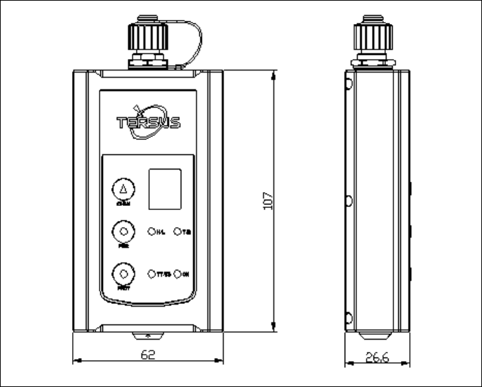
Figure 26 2W /460MHz Radio
Table 9 Button Manual
Button
Description
Channel
Button
Press once, the current channel will be shown.
Press again, the current channel will increase 1, 0~ 9
channels are for use.
Power
Button
Press once to select the output power, which can be 1W or
2W.
Protocol
Button
Protocol button is pressed to switch the protocol between TP
(Transparent EOT protocol) , TT (TT450S protocol) and TS
(Tersus protocol)
!
Two 2W radios must have the same protocol and the same channel
frequency before they can communicate each other.
Channel
Button
Antenna
Interface
Power
Button
Protocol
Button
Current
Channel
Current
Power
Current
Protocol
Data
Interface
ON/OFF
T/R
26 / 76
Table 10 LED Definition
LED
Description
H/L
RED: 2W output is selected,
GREEN: 1W output is selected.
T/R
Blink RED: data is transmitting.
Blink GREEN: data is receiving.
TP/TT/TS
BLUE: Transparent protocol is selected.
RED: TT450S protocol is selected.
BLUE&RED: Tersus protocol is selected.
ON
Is solid on after the power is on.
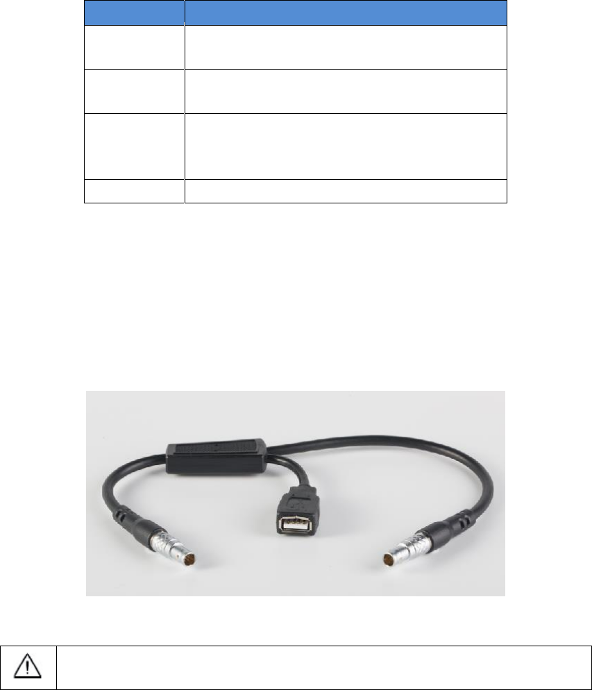
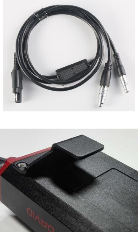
2.3.2 COMM2-7pin-USB & 5pin Cable
The COMM2-7pin-USB & 5pin Cable is used to connect the David to the 2W
radio station & an Android phone, or connect the David to the 30W radio
station & an Android phone. The cable‟s length can be 0.35m or 1m in different
variants.
Figure 27 COMM2-7pin-USB & 5pin Cable
COMM2-7pin-USB & 5pin Cable can only be installed into the COMM2
port of David.
2.4 Base Kit Mobile Mode
In this variant, the David, working as a base, will transmit RTK corrections to a
NTRIP caster or a TCP sever.
The David will be connected to an Android phone with an external Bluetooth or
with cables. Tersus Survey Nuwa® is running in the Android phone to configure
the David.
27 / 76
!
Base Kit Mobile Mode can work independently or work with Rover Kit
Mobile Mode.
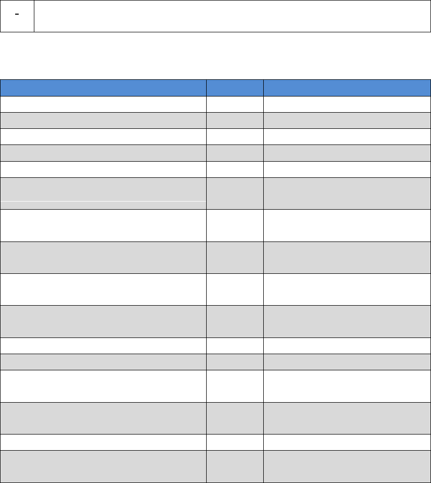
Figure 28 Field Photo 4
!
The tripod, the battery bank and the tribrach are not included in the
package.
Table 11 Base Kit Mobile Mode
Devices
Number
Items in field photo
David GNSS receiver
1
4
GNSS antenna
1
1
GNSS antenna connector
1
2
GNSS antenna cable
1
7
2 Pin-USB power cable
1
6
COMM1-bluetooth module
1
8, refer to 2.1.4
COMM2-7pin-USB & DB9 Data
cable
1
Not in the field photo, refer
to section 2.1.7.
USB Type A Male to USB Type A
Male cable
1
Not in the field photo, refer
to Figure 17
USB Type A Female to USB(Micro +
Type C) OTG cable
1
Not in the field photo, refer
to Figure 18
USB Type A Male to DB9 Male cable
1
Not in the field photo, refer
to Figure 16
1
2
3
4
6
7
8
5
28 / 76
Tape meter
1
See Figure 30
Height measure accessory
1
Not in the field photo, See
Figure 19.
Bracket for base
1
3, see Figure 29
Battery bank
1
5, see Figure 20 and 3.2
Power on David
2.4.1 Bracket for Base
This bracket is hooked on the tripod and all the devices in the field (an Android
phone, a radio, a David and a battery bank) can be installed on it, which brings
much convenience for field job.
Figure 29 Bracket for Base
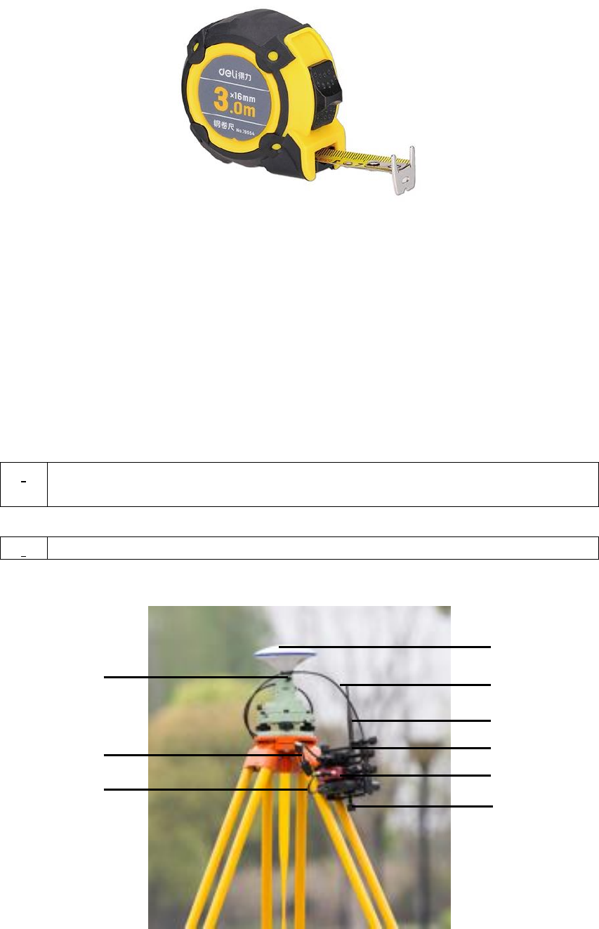
2.4.2 Tape Meter
Working with height measure accessory, the tape meter can give position of a
point on ground with mm-level accuracy.
29 / 76
Figure 30 Tape Meter
2.5 Base Kit with 1W Radio Station
In this variant, the David, working as a base, will transmit RTK corrections to
an external 1W radio.
The David will be connected to an Android phone with cables or with the
Bluetooth module. Tersus Survey Nuwa® is running in the Android phone to
configure the David.
!
Base Kit with 1W Radio Station can work with Rover Kit with 1W Radio
Station only.
Figure 31 Field Photo 5
!
Base Kit with 1W Radio Station can support Base mobile mode.
1
2
3
5
7
8
9
4
6
30 / 76
Table 12 Base Kit with 1W Radio Station
Devices
Number
Items in field photo
David GNSS receiver
1
5
GNSS antenna
1
1
GNSS antenna connector
1
9
GNSS antenna cable
1
2
2 Pin-USB power cable
1
7
COMM1-bluetooth module
1
Not in the field photo, refer to
2.1.4
COMM2-7pin-USB & DB9 Data
Cable
1
8
USB Type A Male to USB Type A
Male cable
1
Not in the field photo, refer to
Figure 17
USB Type A Female to USB(Micro +
Type C) OTG cable
1
Not in the field photo, refer to
Figure 18
USB Type A Male to DB9 Male cable
1
Not in the field photo, refer to
Figure 16
RS900C 1W/915MHz radio
1
4
1W/915MHz radio antenna
1
3
Tape meter
1
See Figure 30Figure 30 Tape
Meter
Height measure accessory
1
Not in the field photo, See
Figure 19.
Bracket for base
1
6
Battery bank
1
see Figure 20 and 3.2 Power
on David
2.6 Base Kit with 2W Radio Station
TBD
!
The tripod, the tribrach and the battery bank are not included in the
package.
31 / 76
2.7 Base Kit with 30W Radio Station
In this variant, the David, working as a base, will transmit RTK corrections to
an external 30W radio.
The David will be connected to an Android phone with cables or with the
Bluetooth module. Tersus Survey Nuwa® is running in the Android phone to
configure the David.
!
Base Kit with 30W Radio Station can work with Rover Kit with 2W Radio
Station only.
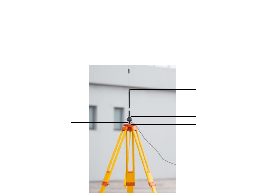
Figure 32 Field Photo 7 - 1
!
Base Kit with 30W Radio Station can support Base mobile mode.
1
2
3
4
32 / 76
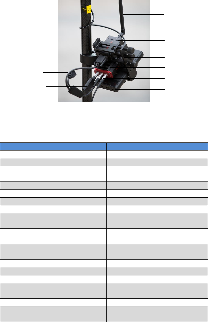
Figure 33 Field Photo 7 - 2
!
The two tripods and the tribrach in Figure 32 and Figure 33 are not
included in the package.
Table 13 Base Kit with 30W Radio Station
Devices
Number
Items in field photos
David GNSS receiver
1
12
GNSS antenna
1
5
GNSS antenna cable
1
7
GNSS antenna connector
2
4
COMM1-bluetooth module
1
Not in the field photo,
refer to 2.1.4
COMM2-7pin-USB & DB9 Data Cable
1
Not in the field photo,
refer to section 2.1.7.
USB Type A Male to USB Type A Male
cable
1
Not in the field photo,
refer to Figure 17.
USB Type A Female to USB(Micro +
Type C) OTG cable
1
Not in the field photo,
refer to Figure 18
USB Type A Male to DB9 Male cable
1
Not in the field photo,
refer to Figure 16.
COMM2-7pin-USB & 5pin Cable (1m)
1
10, refer to Figure 27.
Power cable for 30W radio
1
9, refer to Figure 35
COMM cable for 30W radio
1
11, refer to Figure 36
RS400L30 30W radio
1
8
30W radio antenna
1
1, see Figure 34
5
4
7
8
9
10
10
11
12
13
33 / 76
Metal plate for radio antenna
1
3
Telescopic pole for radio antenna
1
2
Tape meter
1
Not in the field photo,
See Figure 30 Tape
Meter
Height measure accessory
1
Not in the field photo,
See Figure 19.
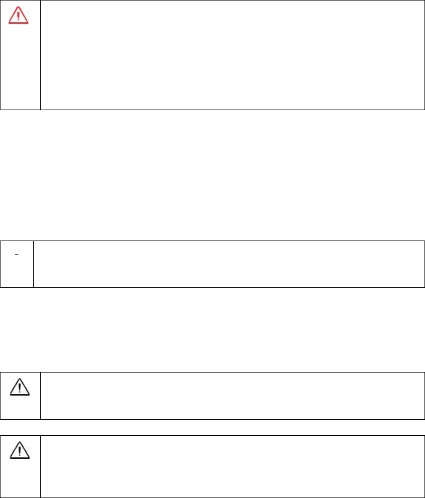
David GNSS receiver installation hook
1
13, see Figure 37
2pin-USB Power Cable
1
Not in the field photo,
see Figure 11
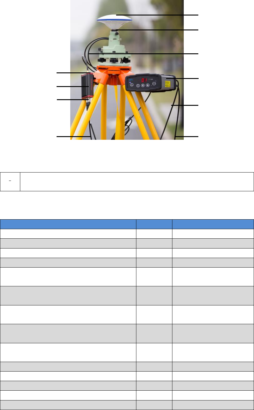
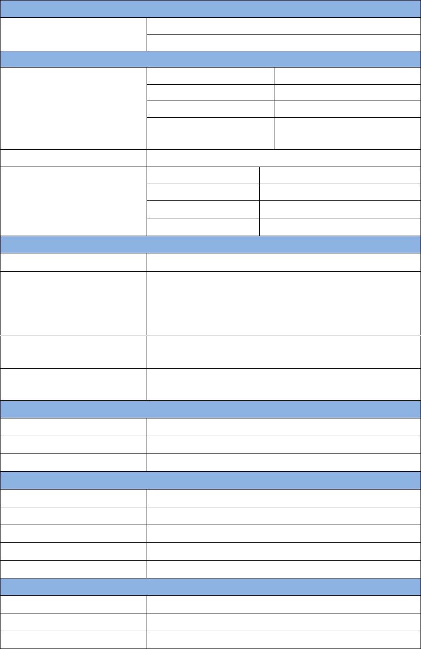
2.7.1 30W Radio
The 30W radio is used when a longer baseline is required. The typical range is
15km, see chapter 5 for detail specification.
Figure 34 30W Radio Station
Table 14 and Table 15 give the definition of the control buttons and the LED,
respectively.
Table 14 The Definition of the Control Buttons
Buttons
Function
ON/OFF
Press 3s to power on or power off the radio
station.
ARROW UP/DOWN
To select the channel
RF PWR
Press 3s to select the RF output power
34 / 76
Table 15 Definition of LEDs
LEDs
Description
ON/OFF
RED: the input voltage is normal.
Blink RED: the input voltage is out of the
limits.
TX/RX
Blink RED: the radio is transmitting.
Blink GREEN if the radio is receiving.
Channel
Show the current channel
BAT CAP
Show the battery left.
RF PWR
Show the current RF output power:
OFF: 30W
BLUE: 20W
RED: 10W
RED+BLUE: 5W
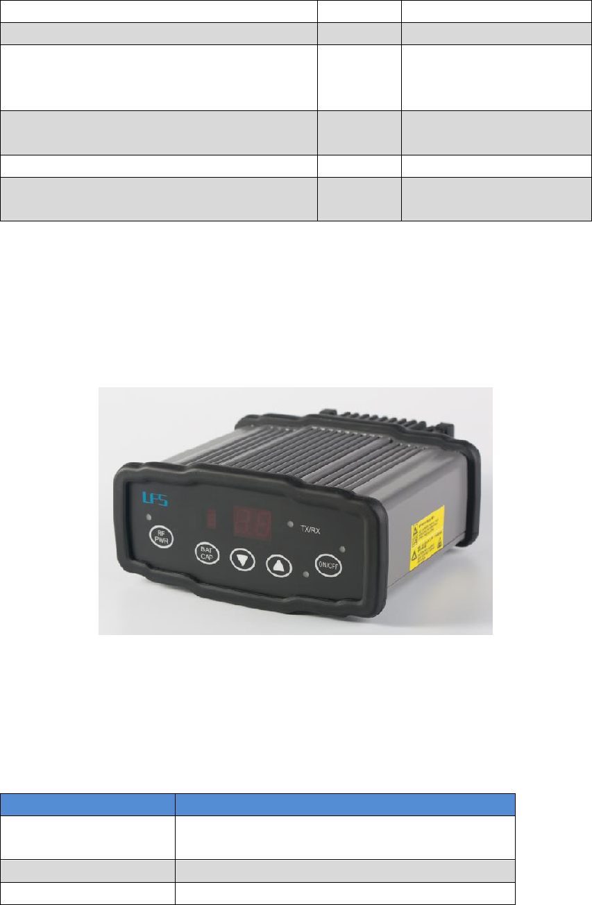
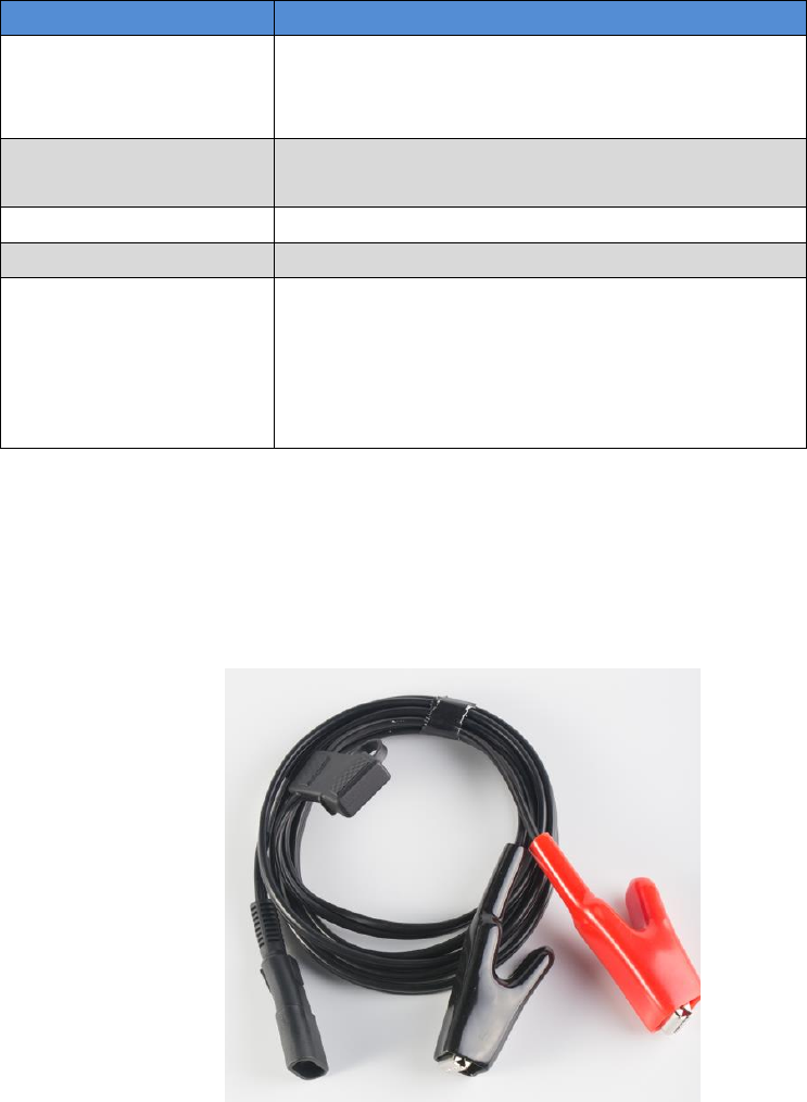
2.7.2 Other cables
Figure 35 Power cable for 30W radio
35 / 76
Figure 36 COMM cable for 30W radio
Figure 37 David GNSS receiver installation hook
36 / 76
3. General operation
The general operation of David is related to the Tersus Survey Nuwa®
software, which will be introduced in the software manual. This chapter only
describes how to do the hardware connection.
3.1 Install the GNSS antenna
Connect the antenna to David with the RF cable. Please ensure the
connectivity is reliable.
!
The ideal place for a GNSS antenna is a point without GNSS signals
blockage from horizon to horizon and is far away from any potential
interfering source.
3.2 Power on David
The input voltage to David is 5 – 12 VDC.
It‟s highly recommended to power on David with an USB port (5VDC
and 2A or more current output) from a battery bank with the power
cable in the package, or the David may not boot up successfully.
After power on, the PV LED will be ON for 3 to 5 seconds, then it will
be OFF, which means the David is booting up successfully.
If the PV LED is NOT acting as the above, it means the David is NOT
booting up successfully.
To make David work, the customer must provide qualified power to
David (refer to chapter 5 for requirement), power to the 30W radio
(if 30W radio is used, refer to chapter 5 for detail) and an Android
phone to run Tersus Survey Nuwa® software.
David may be damaged if devices from other companies are used
to replace the ones in the package. And the warranty may be void
if that happen.
37 / 76
If other power than a battery bank is used to power on David, the
customer has to make a power cable themselves and take all the risks
involved.
The working time of David depends on the capacity of the battery bank.
The following formula can be used to estimate the operating time (assume the
output voltage is 5V):
If no radio or an external 30W radio is connected to the David:
Time (hour) = capacity (mA.Hour) *5 / (1000 * 3.2)
If 1W radio is connected to the David:
Time (hour) = capacity (mA.Hour) *5 / (1000 * (3.0+3.2))
If 2W radio is connected to the David:
Time (hour) = capacity (mA.Hour) *5 / (1000 * (6.5+3.2))
!
1) It‟s highly recommended the capacity of the battery bank is
10,000mA.H or more.
2) The working time above are only theoretical values at 25C
temperature. But according to our experience, the real working time
may be 2/3 of even less of above values.
3.3 Communication between Android phone and David
David can communicate with an Android phone with wires or with Bluetooth.
38 / 76
3.3.1 With Wires
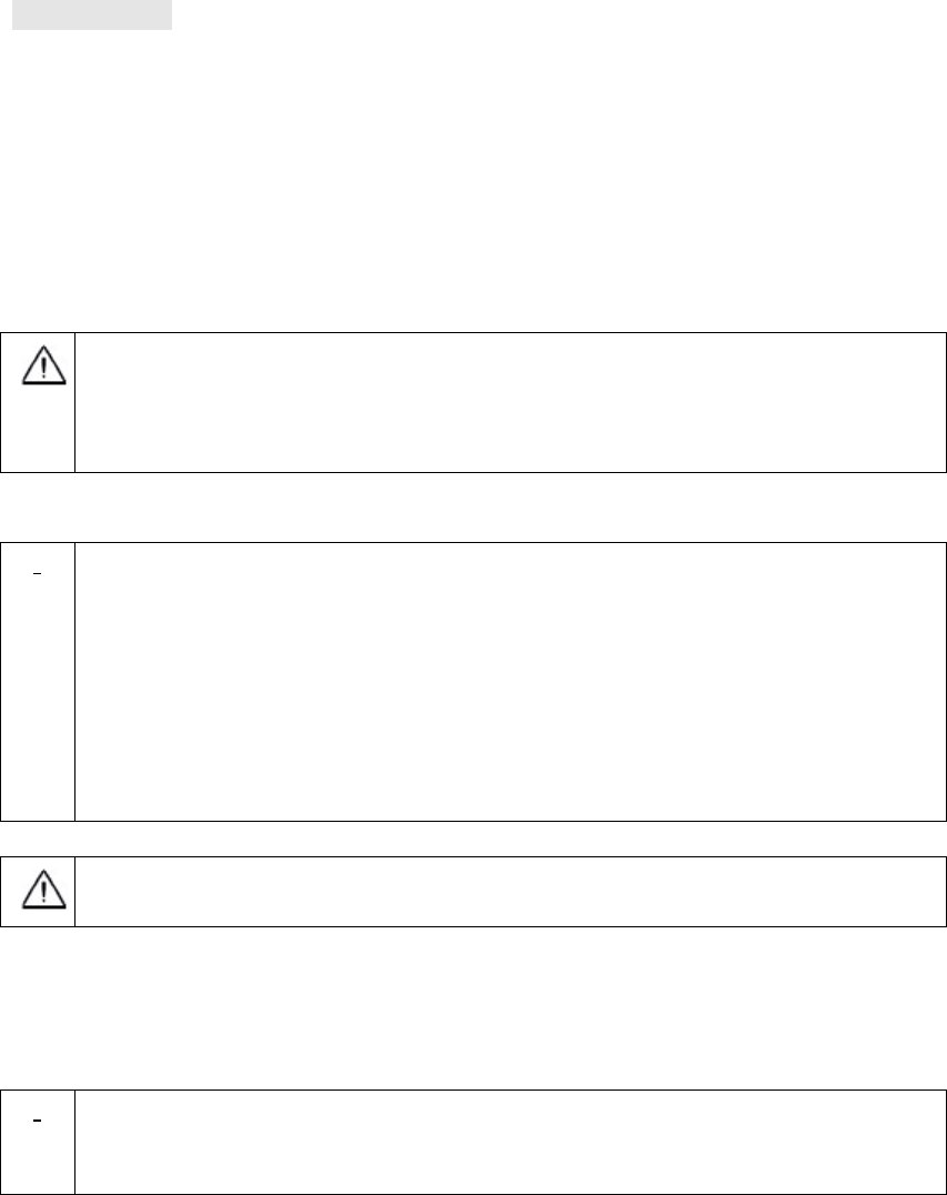
Figure 38 Outline of Android phone to David with Wires
!
Three cables are used to connect the COMM2 port of David to the USB
port of the Android phone. They are:
COMM2-7pin-USB & DB9 Data Cable or COMM2-7pin-USB & 5pin
cable.
USB Type A Male to USB Type A Male cable
USB Type A Female to USB (Micro + Type C) OTG cable
!
The Android phone will NOT be charged when it‟s connected to David
with wires.
39 / 76
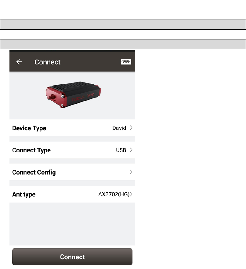
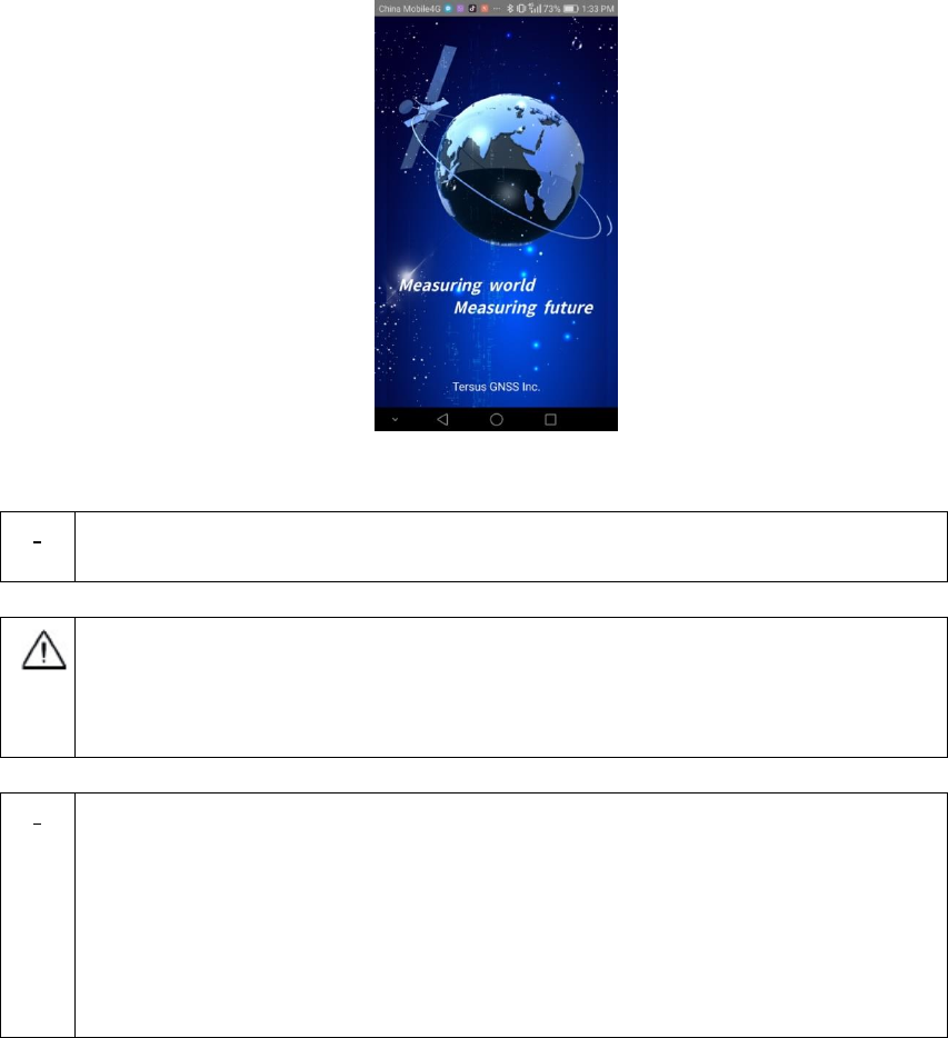
Table 16 Detailed steps
1. Connect the David‟s COMM2 port to the USB port of the Android
phone with cables.
2. Connect the antenna to David with the RF cable (optional).
3. Power on the David with a battery bank.
4. Run Nuwa, Device ->Device Connect
5. Connect Type “ USB”
6. Press Connect Config to
update accordingly.
7. Press Connect to enable
the communication with
the David.
40 / 76
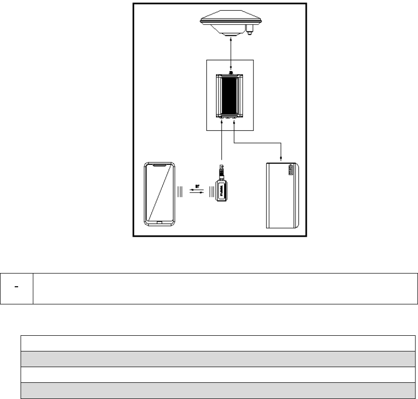
3.3.2 With an External Bluetooth
Figure 39 Outline of Android phone to David with Bluetooth
!
All the seven variants can support connection with Bluetooth as well as
with cables.
Table 17 Detailed steps
1. Install the Bluetooth module to the David‟s COMM1 port.
2. Connect the antenna to David with the RF cable (optional).
3. Power on the David with a battery bank.
4. Run Nuwa, Device ->Device Connect
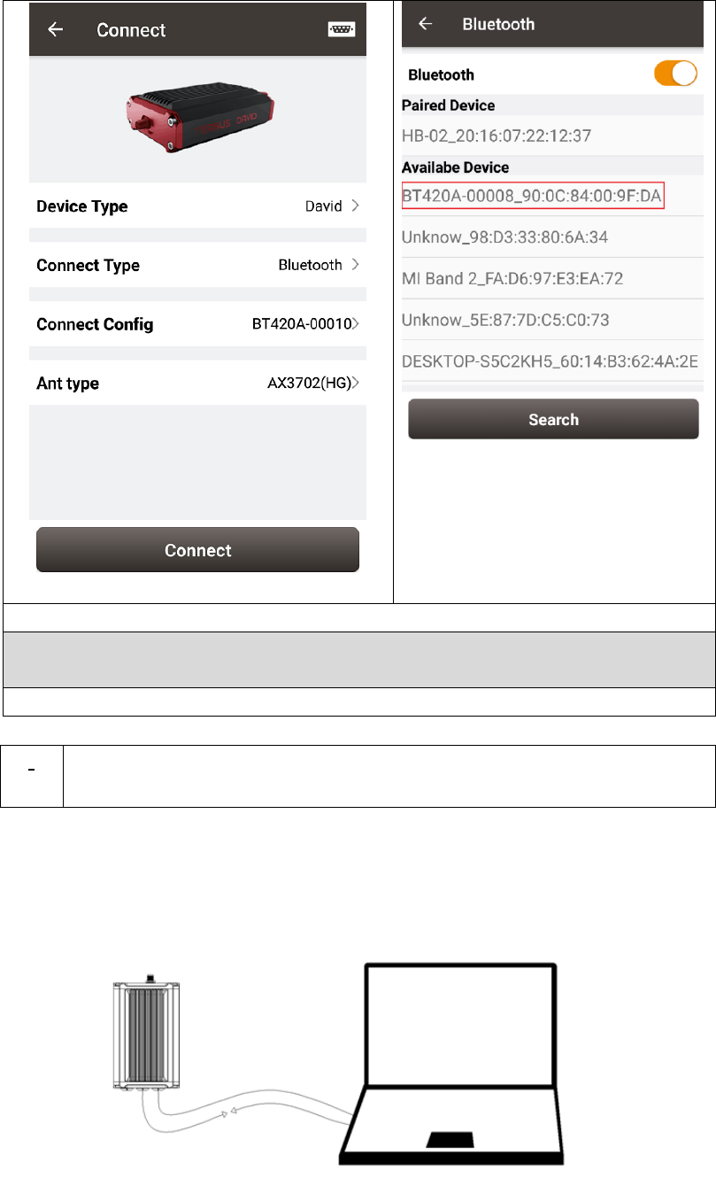
41 / 76
5. Bluetooth is selected for Connect Type
6. Connect Config -> Search. The SSID is BT420A-xxxxx. No password
is needed to pair with it.
7. Press Connect to enable the communication with the David.
!
You can remove a Bluetooth device from the Available Device list by
pressing it for several seconds.
3.4 FW Upgrade & Auth code
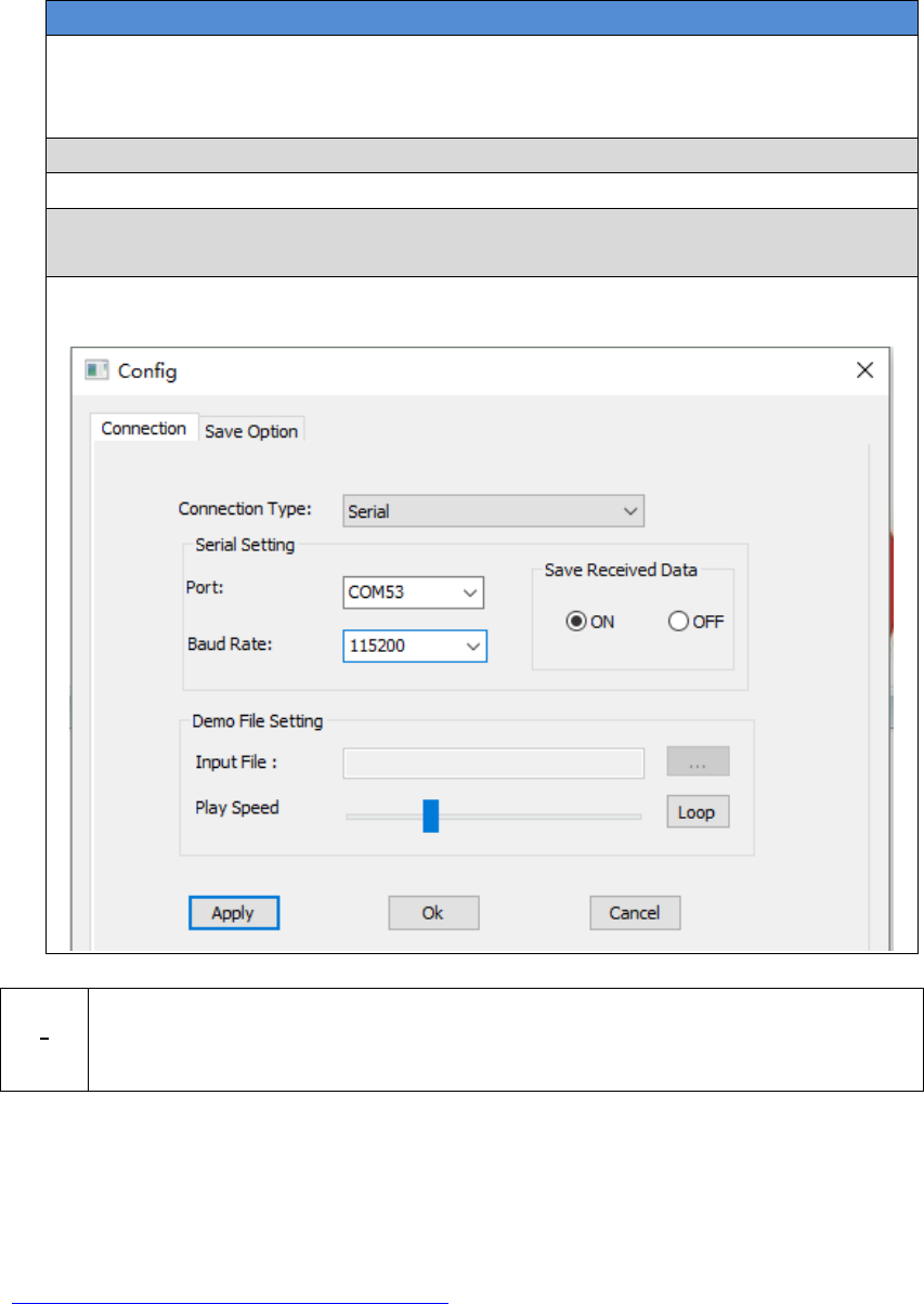
Figure 40 Outline of David connected to a Computer
42 / 76
Table 18 Preparation for FW update
Hardware Installation
1. Install the USB Type A Male to DB9 Male cable to a computer‟s USB
port. The cable will be mapped to a serial port, check the port number
in the Device Manager of the computer.
2. Install the COMM2-USB + DB9 cable to the COMM2 port of the David.
3. Connect the two cables together.
4. Power on the David with the computer‟s USB port or with an external
battery bank.
5. Run Tersus GNSS Center, fill the parameters in the Config page, press
OK to communicate with the David.
!
The default baud rate for the serial port is 115200, which will change to
921600 temporarily during FW updates by Tersus GNSS Center, see
section 3.4.1 Firmware Updates for detail.
3.4.1 Firmware Updates
If a new firmware update is released, it will be available on the Tersus web site
https://www.tersus-gnss.com/software, or you can get the updates from Tersus
support.
The FW version of David receiver can be updated in field. Connect the David
with Tersus GNSS Center, and input „LOG VERSION‟, the following
information will be output:
43 / 76
VERSION COM2 0 0.0 UNKNOWN -1 0.000 00000000 0 20161214
< 1
< BX306 G2SB2G2 008001174910000171 0021 20161123 3.0 Apr
24 2018 12:23:48
0021 is the FW version. See „VERSION‟ in Tersus GNSS Log & Command
Reference document for more detail about this log.
Table 19 Detailed Steps for FW update
Hardware Installation
Follow Figure 40 and the detailed steps in Table 18 to create communication
between a David receiver and Tersus GNSS Center.
Software Configure
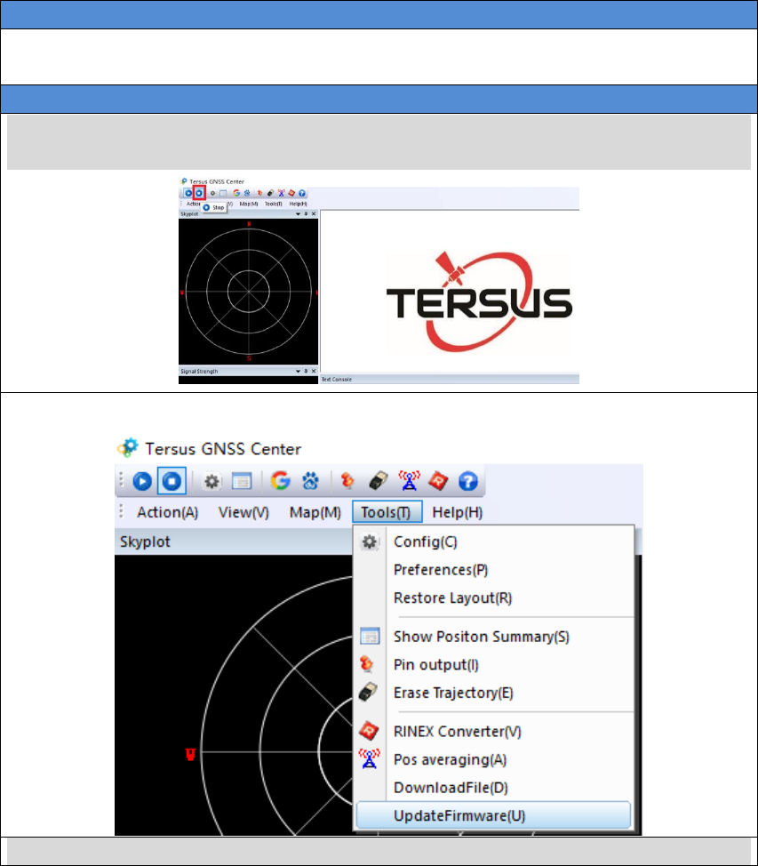
1. Press Stop button to stop the communication between the computer and
the receiver.
2. Select Tools -> UpdateFirmware
3. Select the upgrade file, when a file is selected, the file will be shown in the
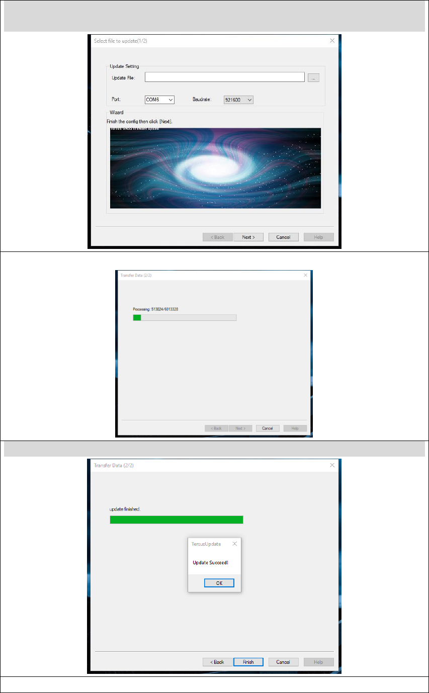
44 / 76
Update File bar. PORT is the PC‟s serial port for the USB Type A Male to
DB9 Male cable. 921600 is recommended for the baud rate. Press Next
4. The following figure shows the FW is upgrading
5. After the FW is upgraded successfully, The following show
6. Press OK and Finish buttons to close the FW update window. Power cycle
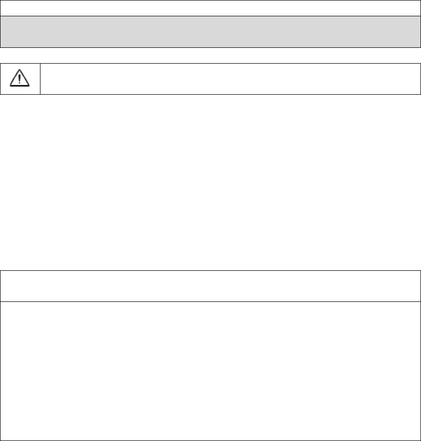
45 / 76
the receiver.
7. After the board is booted, the FW version can be confirmed by connecting
to the receiver and input „LOG VERSION‟ and check the FW version.
After the FW is updated successfully, the David receiver must be
power off for 5 seconds and power on again, or the David will not work.
3.4.2 Auth Code
An auth code is used to determine the features and valid time for a David
receiver. If the auth code is expired, the receiver will not work. And a license
requirement is output from all the ports.
Before you contact Tersus for new auth code, please:
1) Follow Figure 40 and the detailed steps in Table 18 to create
communication between a David receiver and Tersus GNSS Center.
2) Input:
LOG VERSION //get the version info
LOG AUTHLIST //get the auth list info
to the David receiver, and send all the output info to Tersus support. If the auth
code application is approved by Tersus, you will get a reg.txt file, in which
AUTHCODE command with the code will be given, copy all of them and input
them to the David receiver in the console window of Tersus GNSS Center, or
46 / 76
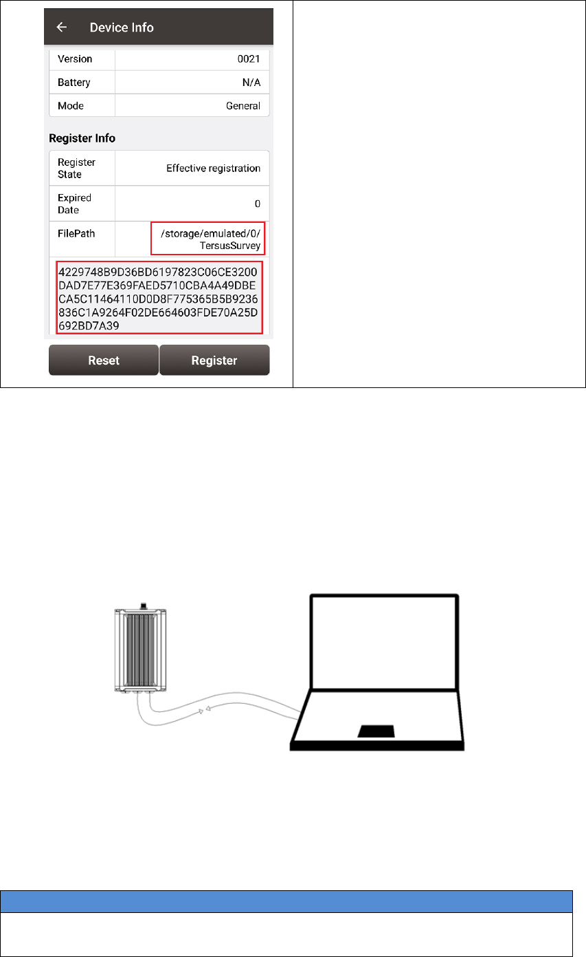
3) Connect the David with Nuwa App,
go to Device -> Device Info, the
right window will be shown
4) Confirm the reg.txt file is copied to
the FilePath.
5) The auth code will be given in the
window below, press Register to
input the new auth code.
3.5 Download Files from Internal eMMC Card
The files saved on David‟s internal eMMC card can be copied to the computer
via a serial port.
Figure 41 Download file from eMMC card
Table 20 Detailed Steps to download files from eMMC card
Hardware Installation
1. Follow Figure 40 and steps 1-5 in Table 18 to create communication
between a David receiver and Tersus GNSS Center.
47 / 76
Software Configure
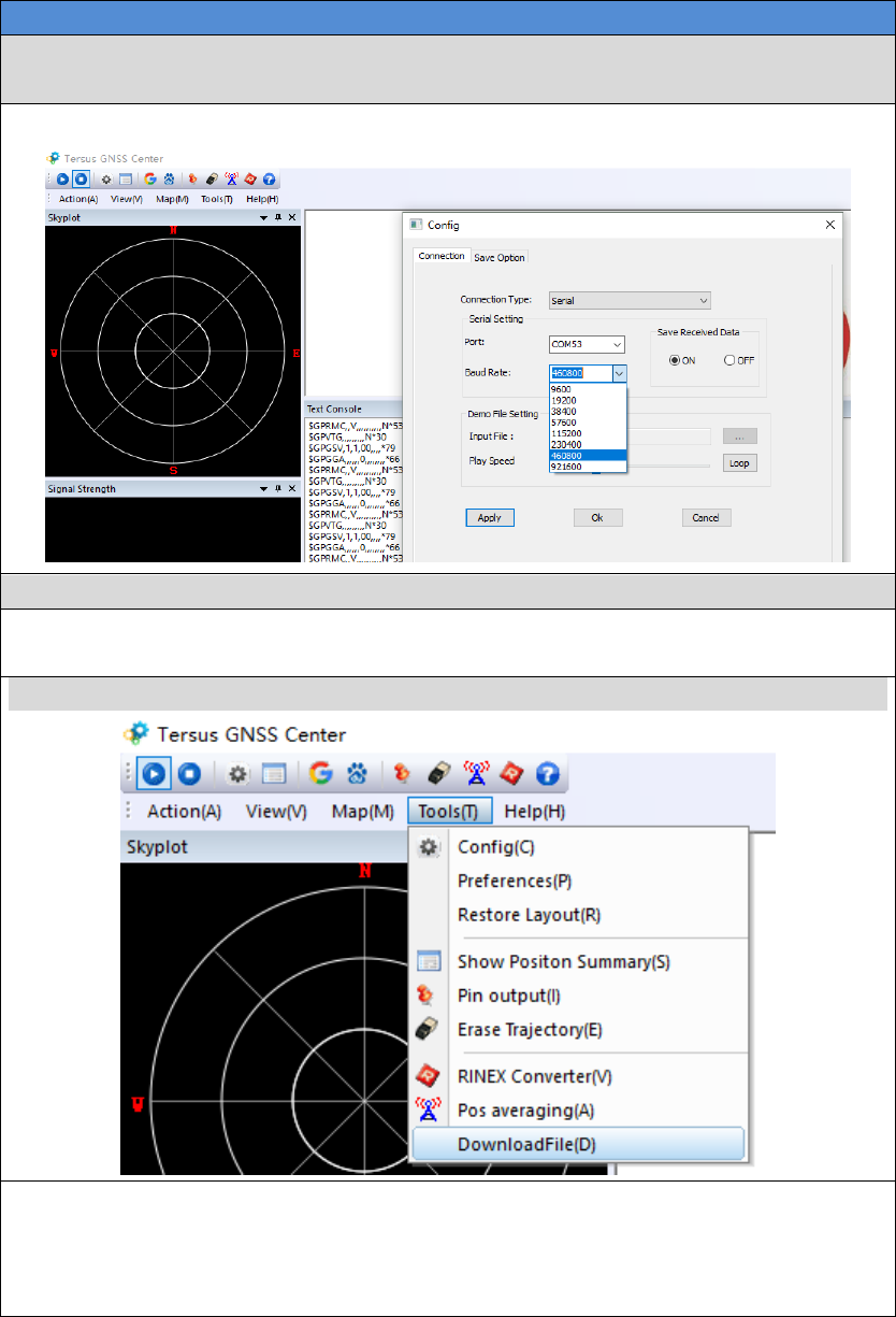
2. Communicate the receiver with Tersus GNSS Center, input:
COM COM2 460800 // Configure baud rate of COM2 to 460800
3. Stop communicate with the David, re-communicate with it with 460800
4. Input LOGFILE CLOSE //close data collection
5. Input UNLOGALL //Stop outputting all the
loggings
6. Press Tools -> Downloadfile
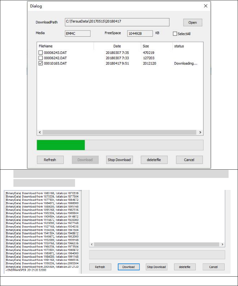
7. All the files on the eMMC card will be shown; the files can be deleted in
this page.
Select the file to be downloaded, press Download button, the following
window will be shown.
48 / 76
8. After the file is downloaded successfully, the follow info will be given in
the console window.
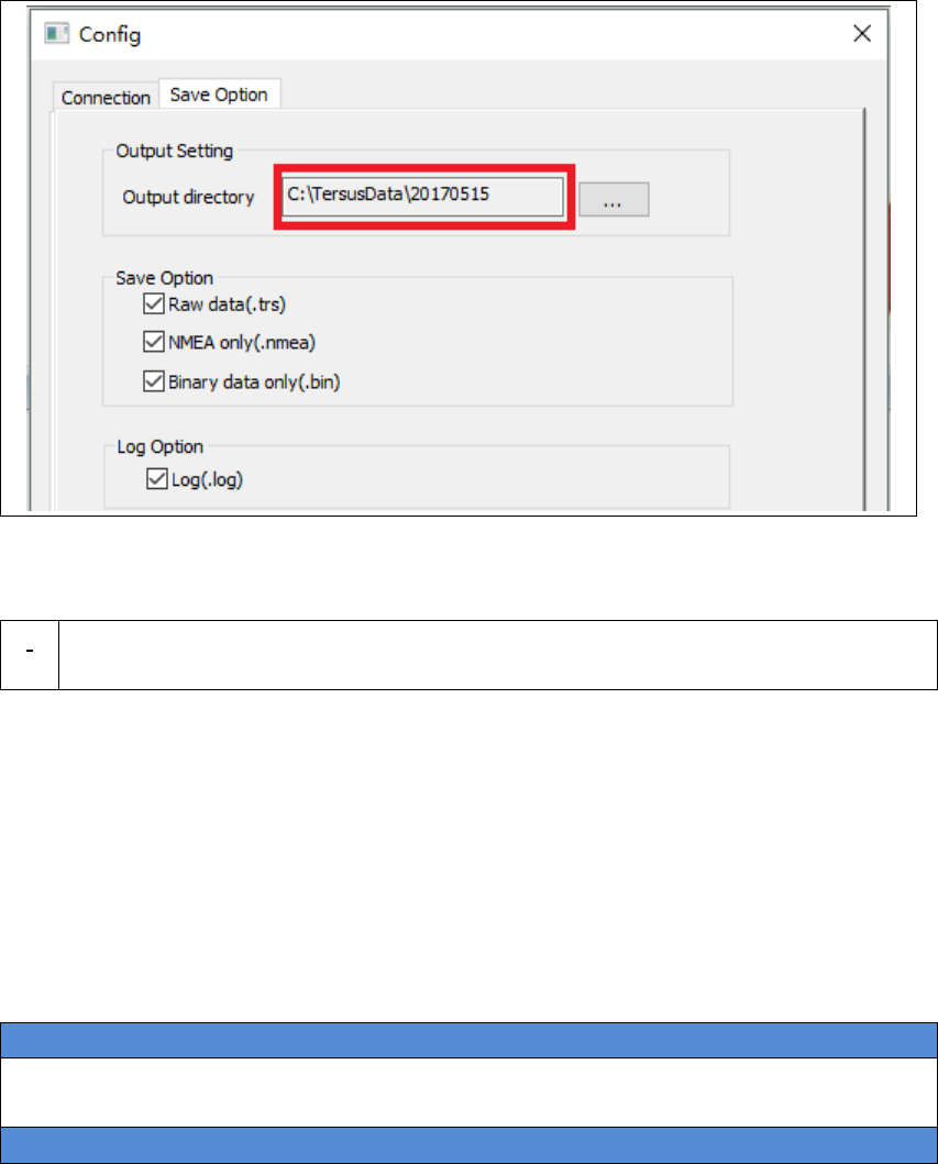
9. Go to Config -> Save Option tab to check where the file is saved.
49 / 76
!
The downloading rate is about 2M/min, the downloading time can be
estimated based on it.
3.6 Input command directly to the GNSS board
Users can input commands to the BX306 board inside the David directly, the
steps are given in Table 21.
Table 21 Input commands to the BX306 directly
Hardware Installation
Follow section 3.3.1 and section 3.3.2 to connect the Android phone to the
David.
Software Configure
50 / 76
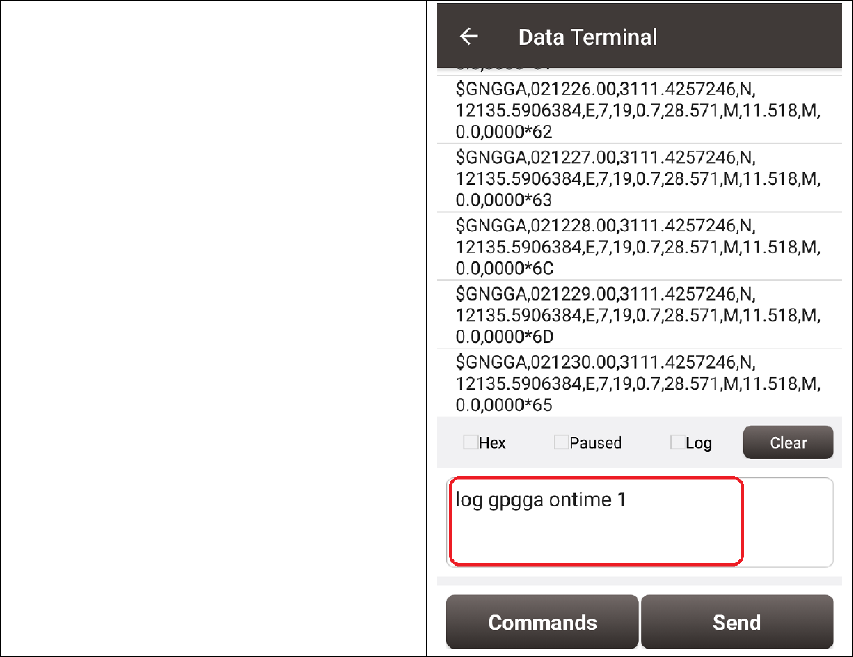
1) Run Nuwa and go to Device ->
Data Terminal
2) The page at the right will be
shown; users can input all the
commands in the Log & Command
document in the window.
3) Then press Send button, the
command will be input to the
BX306 board.
51 / 76
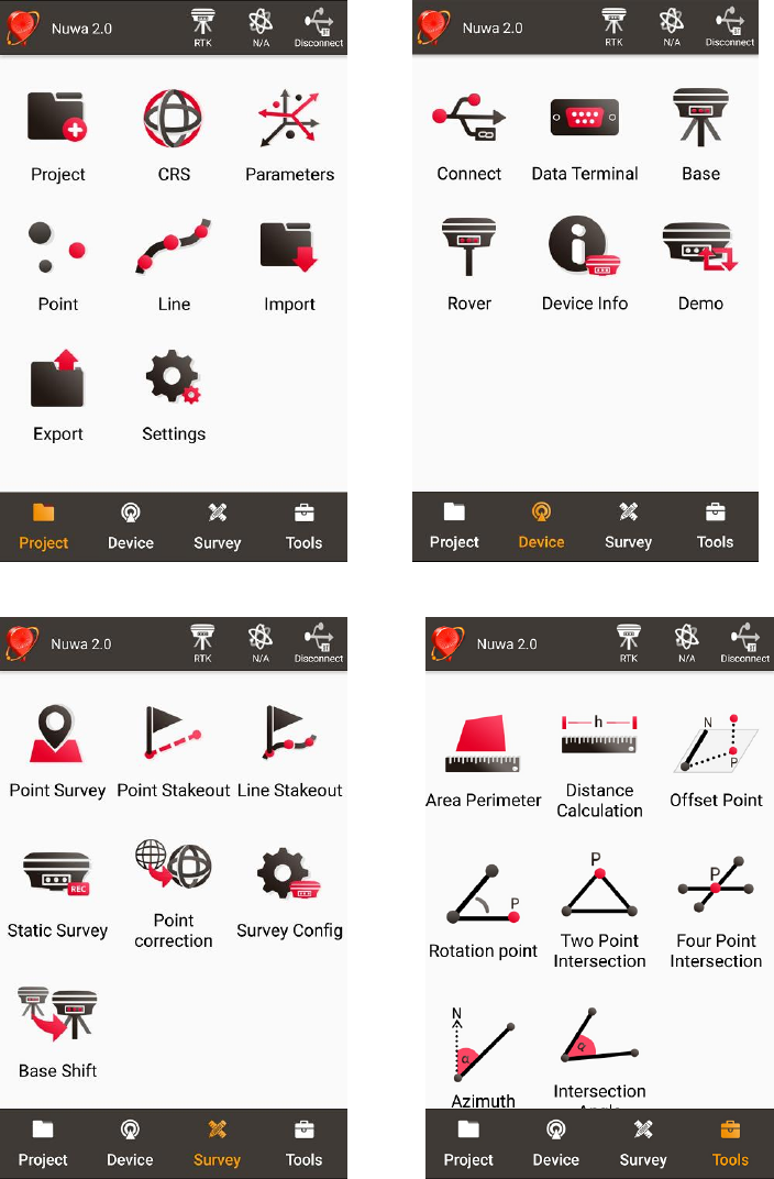
4. Introduction of Nuwa®
Nuwa® is the Tersus survey app, which is running in the Android phone. All
the configure commands for the David are input with Nuwa®, and all the
operation of David are done with Nuwa®. Four tabs menus are provided in
the main window. They are Project, Device, Survey and Tools. See the
Nuwa® user manual for detail.
Figure 42 Booting up page
!
Tersus Survey Nuwa® is supporting Android system; no IOS version is
available now.
The minimal requirements for Android phone:
1) The phone must support OTG, otherwise, it can‟t be connected to
David with cables, but only with Bluetooth.
2) The Android system is 6.0 or later version.
!
1) There are lots of Android versions in market, so an Android phone
meeting the minimal requirements above may still have problems to
run Nuwa.
2) Nuwa is tested with: Huawei Mate 7/Honor 7, Oppo A57, Vivo X9
and Samsung S8.
3) It‟s highly recommended that an Android phone with better hardware
performance than those above is used to run Nuwa.
52 / 76
Figure 43 Four Main Windows of Nuwa
53 / 76
APPENDIX A
5. Specification
5.1 David Receiver
Table 22 David GNSS Performance
GNSS Performance
Position Accuracy
Single positioning
1.5m RMS (Horizontal)
3.0m RMC (Vertical)
RTK Positioning
10mm+1ppm (Horizontal)
15mm+1ppm (Vertical)
Static post processing
3mm+0.5ppm (Horizontal)
5mm+0.5ppm (Vertical)
Time to First Fix
Cold Start: <50s
Warm Start: <30s
Reacquisition
0.5 s L1 (typical)
1.0 s L2 (typical)
Data Rate
Measurements
20Hz
Position
5Hz
Time Accuracy
20ns RMS
Velocity Accuracy
0.03m/s RMS
Measurement Precision
C/A Code
10cm
P Code(zenith direction)
10cm
Carrier Phase(zenith
direction)
1mm
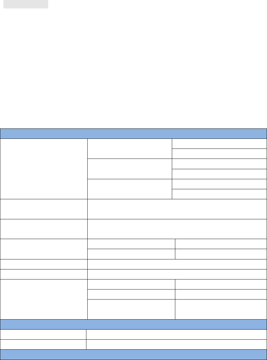
Physical Description
Size
104*65*31 mm3 (David only)
Weight
250g (David only)
Mechanical Drawing
54 / 76
ENVIRONMENTAL
Operating Temperature
-40C to +85C
Storage Temperature
-55C to +95C
Humidity
MIL-STD-810G, Method 507.5 Procedure II (95%)
Random Vibration
MIL-STD 810G Method 514.6, Category 24 (7.7 g
RMS)
Sinusoidal Vibration
IEC 60068-2-6 (5 g)
Bump
ISO 9022-31-06 (25 g)
Shock
Operating: MIL-STD-810G, Method 516.6,
Procedure I (40 g)
Non-operating: MIL-STD-810G, Method 516.6,
Procedure V (75 g)
Water & dust proof
IP67
Power Requirement
Input Voltage
+5 – 12 VDC
Power Consumption
3.2W without external Radio
6.2W with external 1W radio RS900C
9.8W with external 2W radio RS400L2
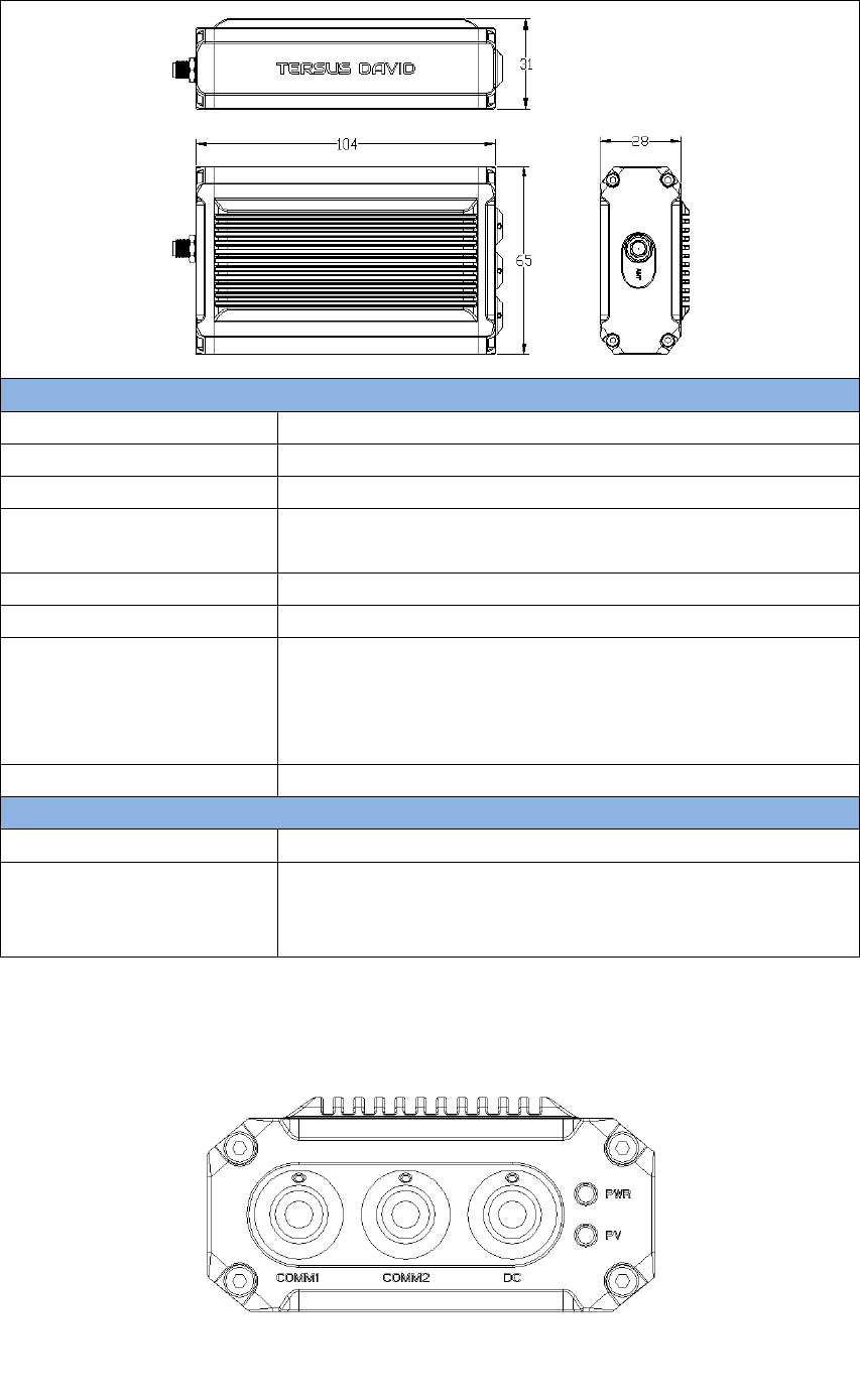
Figure 44 Panel of David
55 / 76
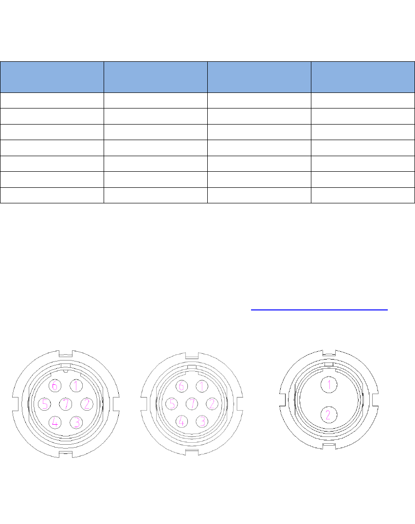
Table 23 Pin Definition
Connector Pin
No.
COMM1
LVTTL
COMM2
RS-232
DC
1
PWR
PWR
PWR
2
GND
GND
GND
3
TXD1
TXD2
4
RXD1
RXD2
5
GND
GND
6
CAN_H/PPS1
USB D+
7
CAN_L/EVENT1
USB D-
Note 1: The default configure for pin6 and pin7 in COMM1 port are CAN_H
and CAN_L. The two signals are multiplexed with PPS and EVENT. This
feature is related to FW release, contact support@tersus-gnss.com for
confirmation.
Figure 45 Pin Definition of the COMM1/COMM2/DC ports
56 / 76
5.2 ANTENNA AX3702 (HG)
Table 24 Antenna AX3702 (HG)
Antenna Specification
Tracking signals
GPS L1/L2/L5; BDS B1/B2/B3;
GLONASS L1/L2
Impedance
50 Ohm
Polarization
RHCP
Axial Ratio
≤ 3dB
Azimuth Coverage
360°
Output VSWR
≤ 2.0
Peak Gain
5.5dBi
Phase Center Error
± 2mm
LNA Specification
LNA Gain
40±2dB
Noise Figure
≤ 2.0dB
VSWR
≤ 2.0
Input Voltage
3.3~12V DC
Operating Current
≤ 45mA
Ripple
± 2dB
Differential
transmission delay
≤ 5ns
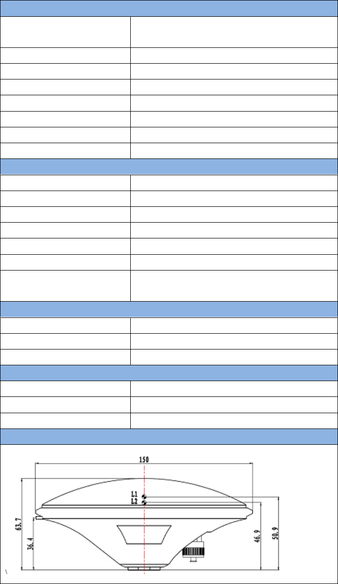
Physical Description
Dimension
Φ150*63.7mm
Signal Connector
TNC Female
Installation connector
5/8‟‟ x 11
Environment
Operating temperature
-40C - +85C
Storage temperature
-55C - +85C
Damp
45% - 95%
Mechanical Drawing
57 / 76
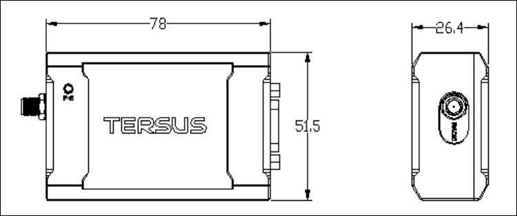
5.3 1W Radio RS900C
Table 25 Specification for RS900C
General Specification
Working Frequency
915MHz
Data level
RS-232
Serial port baud rate
115200
Data interface
DB-9 male
Size
78 * 51.5 * 26.4 mm3
Operating Temperature
-40 - +85℃
Antenna impedance
50
Input voltage
DC 5V – 12V
Power consumption
3.0W (transmitting)
180mW (receiving)
Receiver Specification
Sensitivity
-123dBm (20kbps)
Spurious response immunity
65dB
Intermodulation immunity
60dB
Stand by current
≤ 65mA
saturation
90dB
Distortion
≤ 5%
Error rate
≤ 0.001%
Transmission specification
Modulation
QPSK/BPSK
Transmission power
>1000mW
Modulation distortion
≤ 3%
Maximum frequency deviation
≤ 5KHz
Transmission current
≤ 1000mA/DC 5V
Carrier frequency tolerance
≤ 5*10-6
Spurious frequency components
≤ -65dB
Sleep current
≤ 5uA
Working range
>2km (@1Mbps)
>5Km (@20Kbps)
Mechanical Drawing
s
58 / 76
59 / 76
5.4 2W Radio RS400L2
Table 26 Specification for RS400L2
Communication Interface
Interface
9.6kbps in the air
Lemo connector, RS-232, baud rate 38400
Voltage and Power
Input voltage
DC 5 – 12V
Power
consumption in
transmitting
6.5W (DC 12V, transmitting power 2W)
4W(DC 12V, transmitting power 1W)
Power
consumption in
receiving
<400mW (DC 5V)
External Antenna
Impedance
50 Ohm
VSMR
≤ 1.5
Interface
MCX female
Modulation & Demodulation
Modulation
GMSK
Data rate in air
9600bps@25KHz
RF sensitivity
Better than 13dB@-119dBm
Code sensitivity
-116 dBm BER 10E-5@9600bps
Protocol
Transparent EOT, TT450S and Tersus
RF Specification
Frequency range
10MHz (457MHz – 467MHz)
Channel width
25KHz
Frequency
stability
±1.5 ppm(25C)
Channel number
10 configurable channels
Adjacent channel
selectivity
60dB
Transmission
power
High power
(2W)
33.5 0.5dBm@DC5.5V
Low power
(1W)
30.0 0.5dBm@DC5.5V
Environment
Temperature
-30C - +60C (operating)
-40C - +85C (storage)
Mechanical
Size
107 * 62 * 26.6
60 / 76
61 / 76
5.5 30W Radio RS400L30
Table 27 RS400L30 Radio Specification
Communication Interface
DTE-DCE Interface
9.6kbps in the air
Serial port: RS-232, Band rate 38400
Interaction
Power level
High (about 30W)
PWR LED: OFF
2nd high (about 20W)
PWR LED: BLUE
Middle (about 10W)
PWR LED: RED
Low (about 5W)
PWR LED: RED&BLUE
blink
Charging Alarm
DC 11.60 0.2V
Battery Monitor
B4
DC 13.00 0.2V
B3
DC 12.50 0.2V
B2
DC 12.00 0.2V
B1
DC 11.60 0.2V
Power In/Out
Input voltage
DC 10.5 – 15.0V
Power in transmitting
(typical)
85W (DC 12.8V, 30W output)
65W (DC 12.8V, 20W output)
46W (DC 12.8V, 10W output)
33W (DC 12.8V, 5W output)
Transmitting prohibition
voltage
DC 11.40 0.2V (default)
DC 10.50 – 11.5V (configure range)
Power in receiving
(typical)
<3W (Input voltage DC 12.8V)
Antenna
Input Impedance
50 Ohm
VSWR
≤ 1.5
Interface
TNC female
Modulation/Demodulation
Modulation
GMSK
Data rate in air
9600bps@25KHz
RF sensitivity
Better than 13dB@-119dBm
Decode sensitivity
-116 dBm BER 10E-5@9600bps
Protocol
Transparent EOT, SOUTH
Radio
Frequency range
457 – 467MHz
Channel width
25KHz
Stability
1.5ppm (25C)
62 / 76
Channel number
116 (channel 00 – 15 are configurable, channel
16 – 116 are fixed)
Adjacent channel
selectivity
60dB
Environment
Temperature
Operating
-30 – +60C
Storage
-40 – 85C
Dust proof and
waterproof
IP68
Physical Description
Size
165 * 74 * 185.5 mm3 with plastic protector
Weight
About 1.75Kg
Data port
LEMO EGA.0B.305
Power input port
LEMO EGG.1B.302
Installation
Hook
Mechanical Drawing
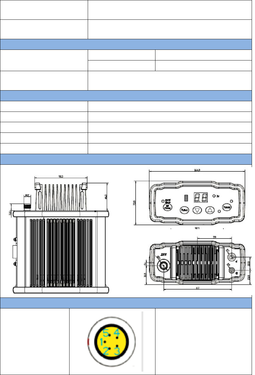
Signal definition
Data Port
Pin 1: GND
Pin 2: GND
Pin 3: Output power (3A,
same voltage as the input)
Pin 4: RXD
Pin 5: TXD

63 / 76
Power input port
Pin 1: GND
Pin2: PWR input
64 / 76
APPENDIX B
6. Typical operating
The LEMO connectors in the David system support mis-installation
avoidance. But it‟s highly recommended to double check the
module/cable before they are installed to the correct ports.
Mis-installation with force can damage the David.
!
The following may be used for David system:
A battery bank for David
An Android phone
An external large capacity power if a base kit with 30W or with 2W
radio station is used.
A tripod (optional).
A tribrach (optional)
It‟s highly recommended that a David base variant is installed on a
tripod.
6.1 David as a Rover to receive corrections from Internet
!
From section 6.1 to section 6.4, David and Android phone are
connected with cables; refer to section 3.3.2 for the connection with
Bluetooth.
65 / 76
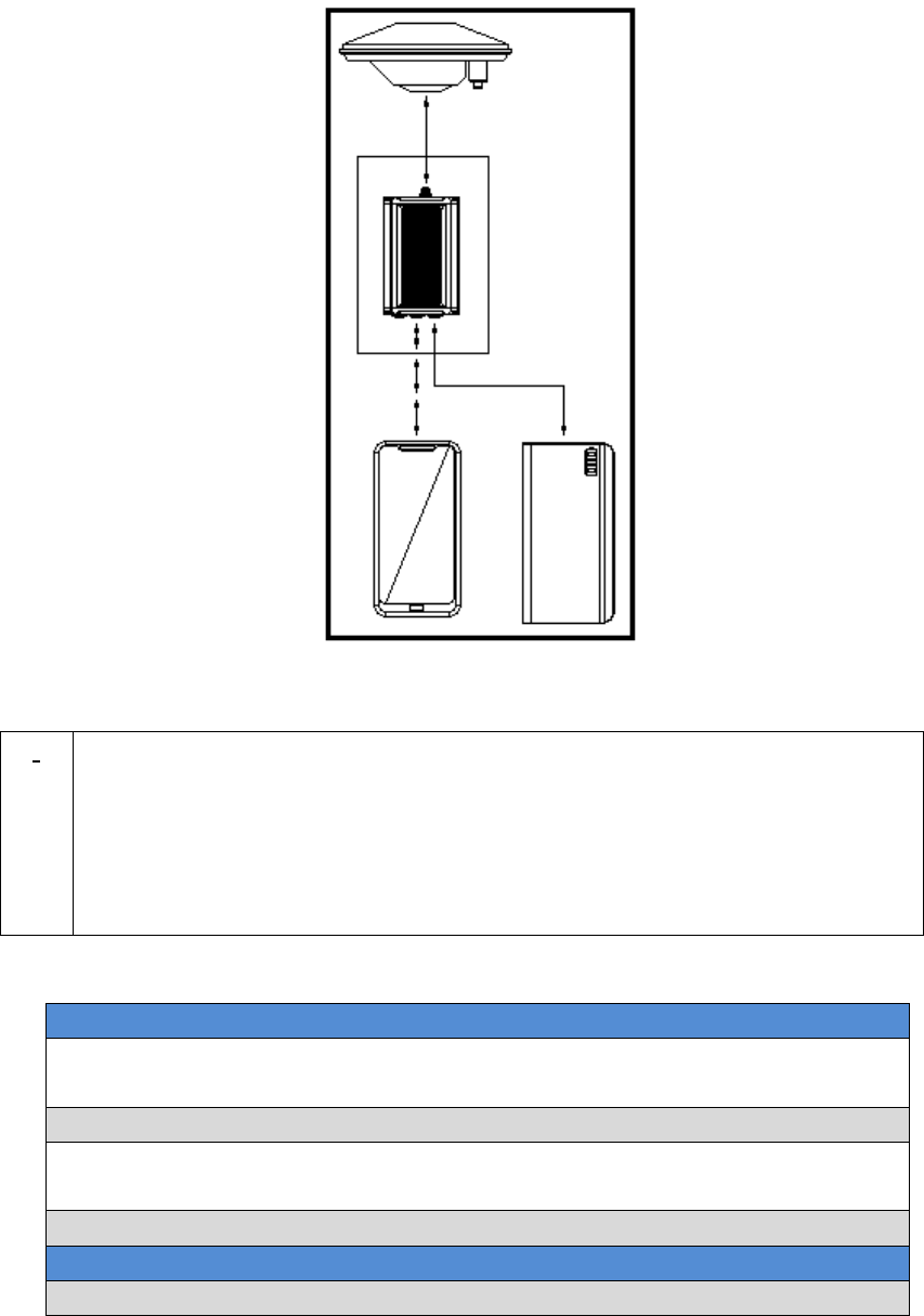
Figure 46 Outline of Android phone to David with Wire
!
Three cables are used to connect the COMM2 port of David to the USB
port of the Android phone. They are:
COMM2-7pin-USB & DB9 Data Cable or COMM2-7pin-USB & 5pin
cable.
USB Type A Male to USB Type A Male cable
USB Type A Female to USB (Micro + Type C) OTG cable
Table 28 Detailed steps for rover receive corrections from Internet
Hardware Installation
1. Install the GNSS antenna on a tripod or on a ranging pole at a point
interested.
2. Connect the antenna to David with the RF cable.
3. Connect the David‟s COMM2 port to the USB port of the Android
phone with cables.
4. Power on the David with a battery bank.
Software Configure
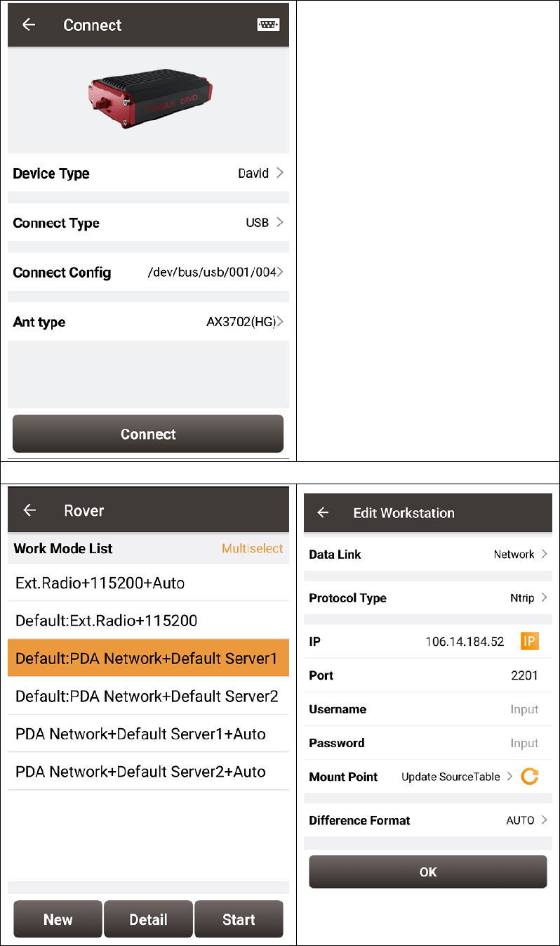
5. Run Nuwa, Device ->Device Connect
66 / 76
6. Connect Type “ USB”
7. Press Connect Config to
update accordingly.
8. Press Connect to enable the
communication with the
David.
9. Go back to: Device -> Rover Station
67 / 76
10. Select PDA Network+Default
Server1, then press Detail to
configure the parameters about
the Network.
11. Select Network for Data Link
12. If Ntrip is selected for Protocol
type, please input: IP, Port,
Username, Password and Mount
Point.
13. If TCP is selected for Protocol
type, please input: IP and Port.
14. Go back to the Rover Station
page and press “Start”.
15. If all the configure above are
correct, the right page will show
the rover is receiving RTK
corrections.
6.2 David as a Base to transmit corrections to Internet
Figure 47 Outline of Android phone to David with Wire
!
Three cables are used to connect the COMM2 port of David to the USB

68 / 76
port of the Android phone. They are:
COMM2-7pin-USB & DB9 Data Cable or COMM2-7pin-USB & 5pin
cable.
USB Type A Male to USB Type A Male cable
USB Type A Female to USB (Micro + Type C) OTG cable
Table 29 Detailed steps for Base transmit corrections to Internet
Hardware Installation
1. Install the tripod at a point interested.
2. Install a tribrach on the tripod, adjust it to horizontal level and install
the GNSS antenna and the antenna connector on it.
3. Connect the antenna to David with the RF cable.
4. Connect the David‟s COMM2 port to the USB port of the Android
phone with cables.
5. Power on the David with a battery bank.
Software Configure
6. Run Nuwa, Device ->Device Connect
7. Connect Type “ USB”
8. Press Connect Config to
update accordingly.
9. Press Connect to enable the
communication with the
David.
10. Go back to: Device -> Base Station
!
It‟s highly recommended that a base David is installed on a tripod.
69 / 76
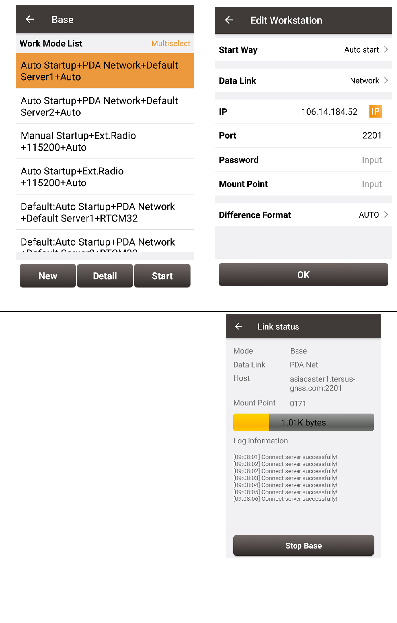
11. Select Auto Startup+PDA
Network+Default Server1+Auto,
then press Detail to configure the
parameters about the Networ
12. If Auto Start is selected for Start
Way, go to Step 14.
13. If Manual Start is selected for
Start Way, input the base‟s
position manually.
14. If Ntrip protocol is selected,
please input: IP, Port, Username,
Password and Mount Point.
15. If TCP is selected for Data Link,
please input: IP and Port.
16. Go back to the Base Station page
and press “Start”
17. If all the configure above are
correct, the right page will show
the base is transmitting RTK
corrections.
70 / 76
6.3 Radios Transmit RTK Corrections between Two Davids
!
1W base must work with 1W rover.
2W base must be work with 2W rover.
30W base must work with 2W rover.
Only 30W base and 2W rover are given in this section since the other two
configure are very simple.
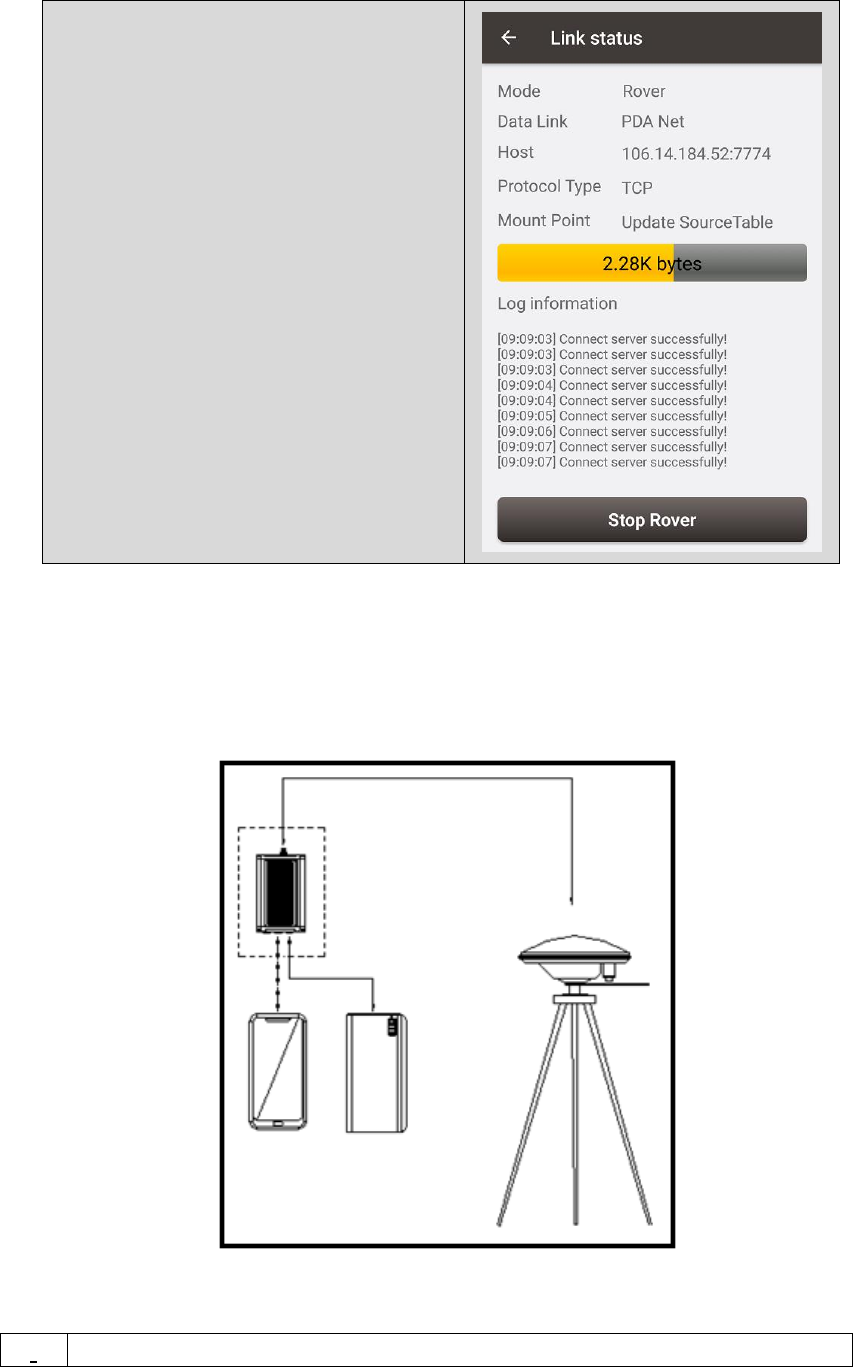
Figure 48 Outline of Base/Rover with Radios
Table 30 Detailed steps for David with Radios
Hardware Installation for the 30W Base
1. Install the two tripods at the points interested.
2. Install the 30W radio antenna with the telescopic pole for radio
antenna.
3. Refer to Figure 32, install the metal plate, the GNSS antenna
connector and the 30W radio antenna on one tripod.
4. Install a tribrach on the other tripod, adjust it to horizontal level and
install the GNSS antenna and the antenna connector on it.
5. Connect the antenna to the base David with the RF cable.
6. Connect the David‟s COMM2 port to the USB port of the Android
phone with cables.
7. Install the RF cable from the telescopic pole to the 30W radio station.
8. Connect the COMM cable to 30W radio, and to the base Daivd‟s DC
port, respectively. Then connect it to the power cable for 30W radio.
9. Double check the cables above and connect the power cable to the
external battery.
Hardware Installation for the 2W Rover
10. Install a tripod at the point interested.
11. Install a tribrach on the tripod, adjust it to horizontal level and install
the GNSS antenna and the antenna connector on it.
BASE
Rover
71 / 76
12. Connect the rover antenna to the rover David with the RF cable.
13. Install the COMM2-7pin-USB & 5pin cable to the COMM2 port of the
rover David, and connect the other two connectors to the USB port of
the Android phone with cables and to the 2W radio station,
respectively.
14. Power on the David with an external battery bank.
Software Configure for the 30W Base
15. Refer to 3.3.1 to communicate the Android phone with the base David.
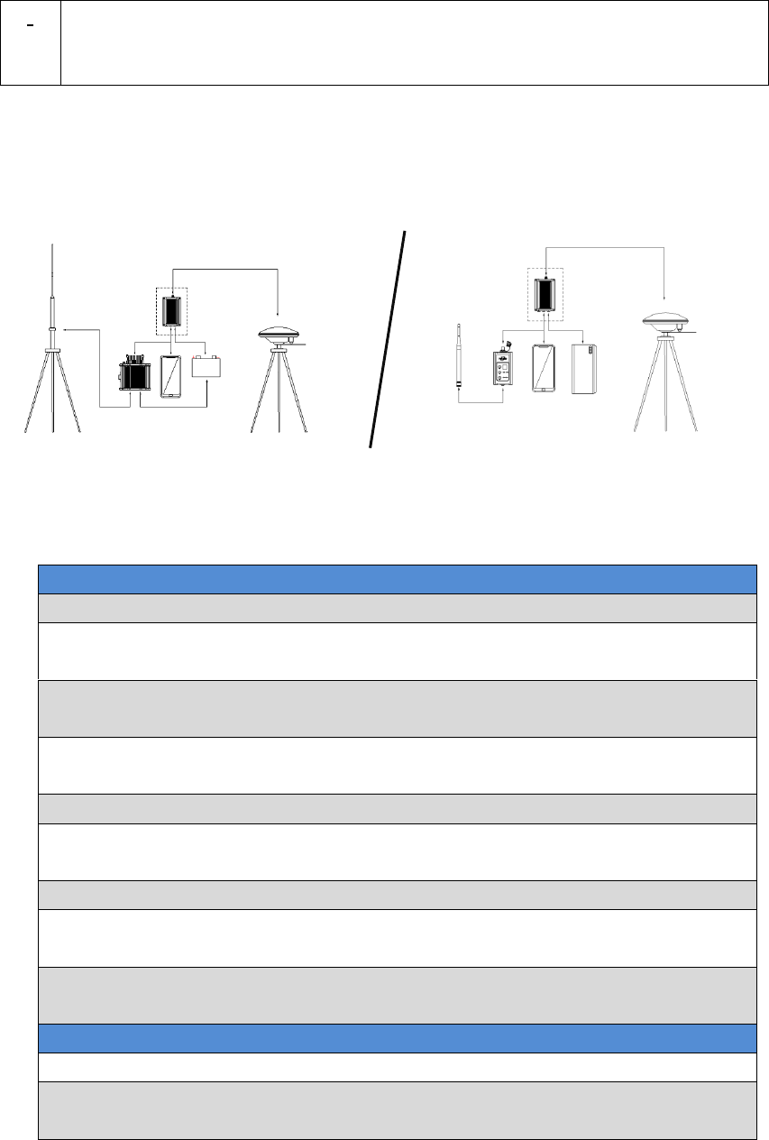
16. In Survey Nuwa, go to: Device -> Base Station
17. Select Auto Startup+Ex.Radio+115200+Auto, press Detail
18. If Auto Start is selected for Start Way, go to Step 20.
19. If Manual Start is selected in for Start Way, input the base‟s position
manually.
20. Press OK to go back to the Base page, press Start.
Software Configure for the 2W Rover
21. Refer to 3.3.1 to communicate the Android phone with the rover
David.
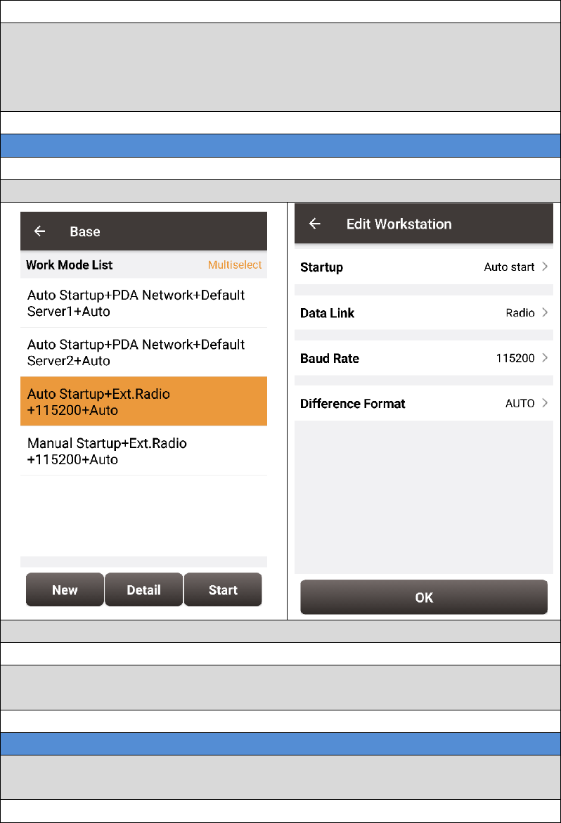
22. Go back to: Device -> Rover Station
72 / 76
23. Select Ext.Radio+115200+Auto, press Detail
24. Data Link is Radio and ensure the Band Rate is correct.
25. Go back to the rover page, and press Start.
6.4 Data Collection for Post Processing
!
The size of the logging:
Collect raw measurements at 1Hz (about 110KByte/min if 20 satellites
are tracked, about 165KByte/min if 30 satellites are tracked)
If the collection frequency increased, the data size will be increased
proportionately.
David provides up to 4GB internal eMMC card for data collection,
before data collection, estimate whether the free space is enough for
the data collection. Refer to Table 20 to delete the files on eMMC card
to get more free space.
During data collection, the antenna must be installed on a tripod.
73 / 76
!
Rules for the file name & update time in the internal eMMC card:
1) Name: file name is the 00..00xx..xx.dat, totally 8 digits, in which xxxx
is the working time (seconds/100) of the David. For example, the
David has worked 500 hours 40min, (500*3600 + 40*60)/100 =
18024, the file name will be 00018024.dat.
2) Update time: if the David hasn‟t gotten the GNSS time, the update
time of the files will be19800000 0:0 (YYYYMMDD HH:MM). If the
David has gotten the GNSS time, the update time will be the UTC
time.
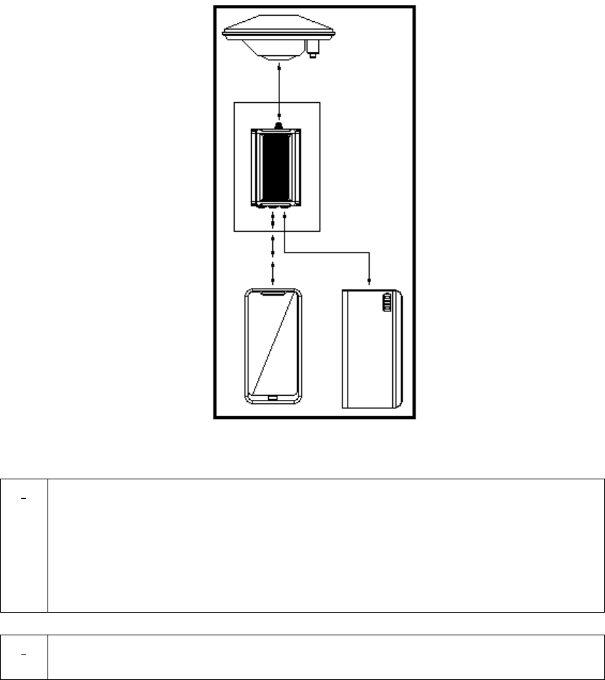
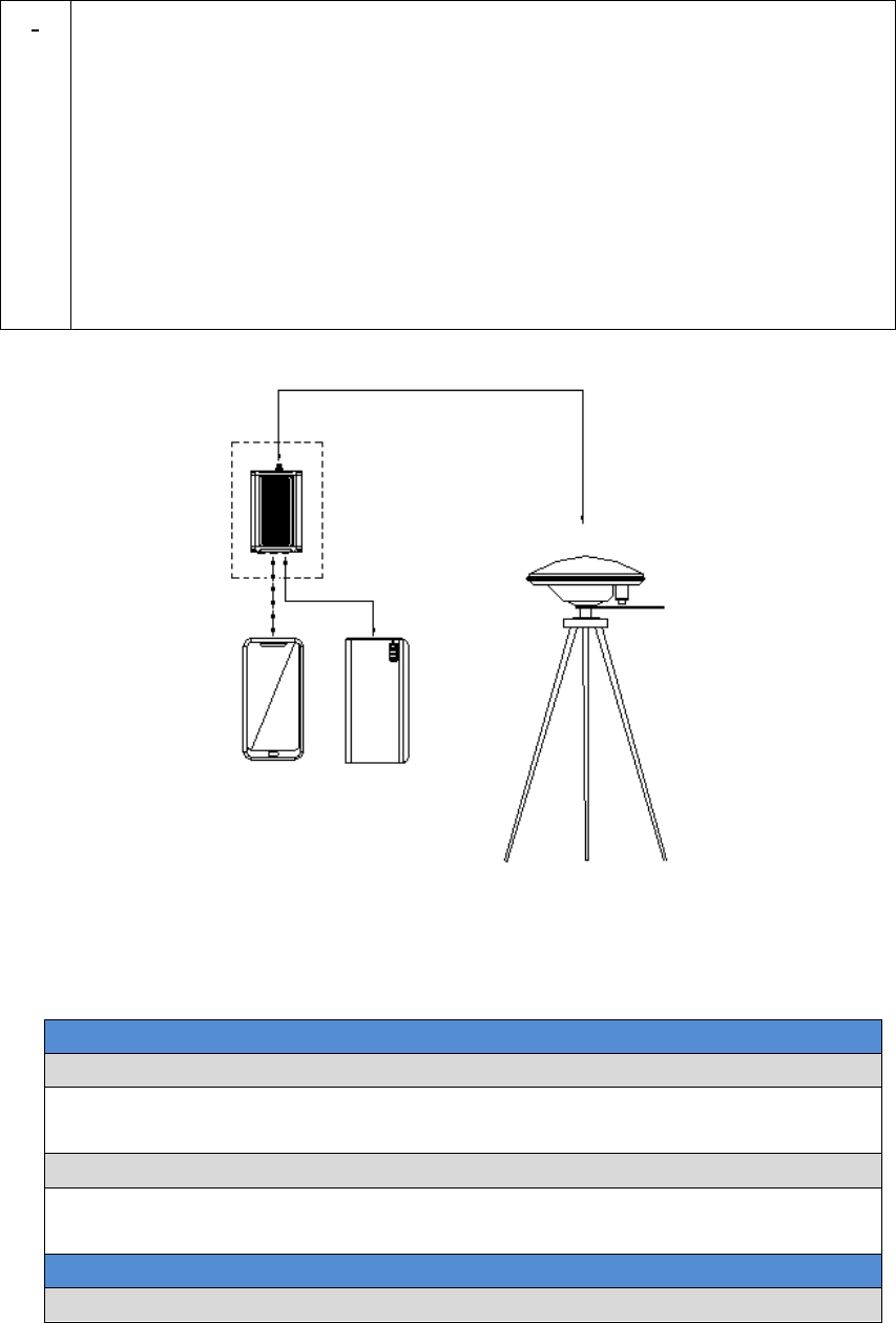
Figure 49 Outline of Static Data Collection
Table 31 Detailed Steps for Static Data Collection
Hardware Installation
1. Install a tripod at a point interested.
2. Install a tribrach on the tripod, adjust it to horizontal level and install
the GNSS antenna and the antenna connector on it.
3. Connect the antenna to the David with the RF cable.
4. Create communication between the David and the Android phone with
cables, refer to section 3.3.1.
Software Configure
5. In Tersus Survey Nuwa, go to Survey->Static Survey
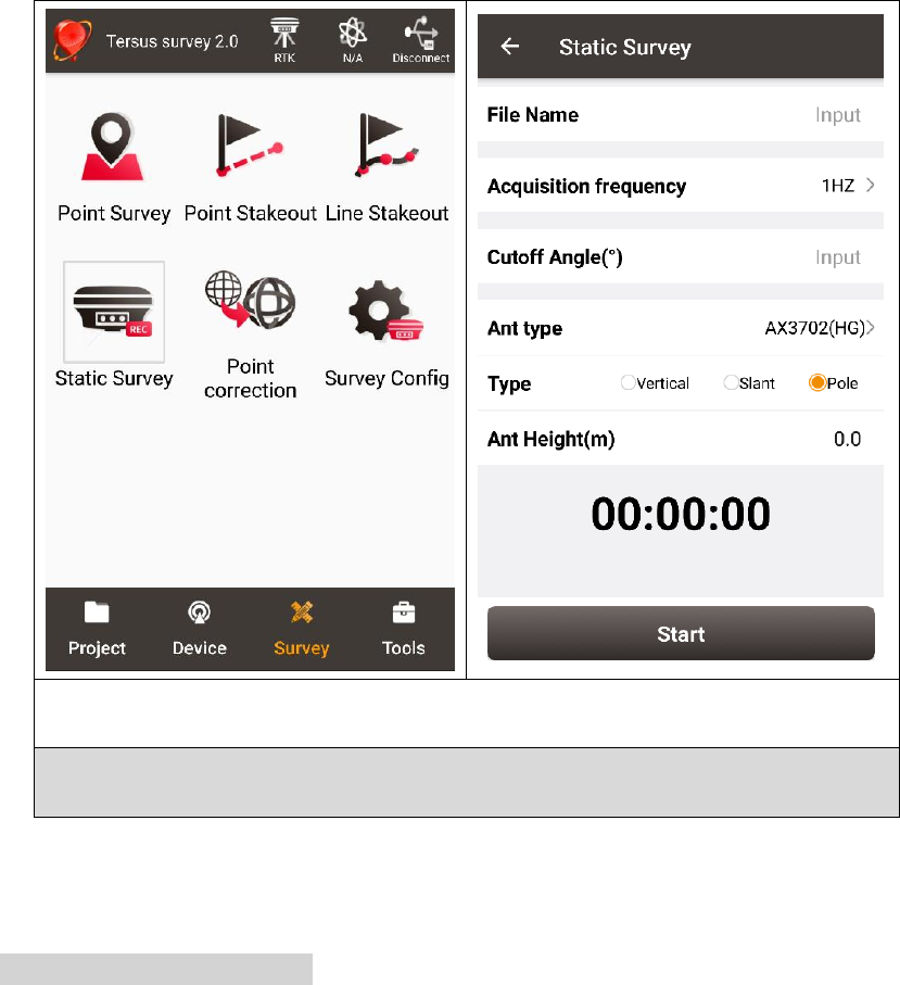
74 / 76
6. Ensure the necessary parameters, including file name, data frequency
and cutoff angle, etc. Press Start.
7. Follow steps 1 - 6 above to collect static data at other points
interested.

75 / 76
7. Terminology
Table 32 List of terminology
Abbreviation
Definition
ASCII
American Standard Code for Information Interchange
CMR
Compact Measurement Record
DC
Direct Current
ESD
Electro Static Discharge
ECEF
Earth Center Earth Fixed
GLONASS
GLObal NAvigation Satellite System
GNSS
Global Navigation Satellite System
GPS
Global Positioning System
IF
Intermediate Frequency
IMU
Inertial Measurement Unit
IO
Input/Output
LED
Light Emitting Diode
LNA
Low Noise Amplifier
MPU
Micro Processing Unit
NMEA
National Marine Electronics Association
PC
Personal Computer
PPS
Pulse Per Second
RF
Radio Frequency
RINEX
Receiver Independent Exchange format
RMS
Root Mean Squares
RTK
Real-Time Kinematic
RTCM
Radio Technical Commission for Maritime Services
SMA
Sub-Miniature-A interface
TTFF
Time to First Fix
TTL
Transistor-Transistor Logic level
UART
Universal Asynchronous Receiver/Transmitter
USB
Universal Serial BUS
WGS84
Word Geodetic System 1984
FCC Caution.
This device complies with part 15 of the FCC Rules. Operation is subject to the following two
conditions:
(1) This device may not cause harmful interference, and
(2) this device must accept any interference received, including interference that may cause
undesired operation.
Any Changes or modifications not expressly approved by the party responsible for compliance
could void the user's authority to operate the equipment.
Note: This equipment has been tested and found to comply with the limits for a Class B digital
device, pursuant to part 15 of the FCC Rules. These limits are designed to provide reasonable
protection against harmful interference in a residential installation. This equipment generates
uses and can radiate radio frequency energy and, if not installed and used in accordance with the
instructions, may cause harmful interference to radio communications. However, there is no
guarantee that interference will not occur in a particular installation. If this equipment does
cause harmful interference to radio or television reception, which can be determined by turning
the equipment off and on, the user is encouraged to try to correct the interference by one or
more of the following measures:
-Reorient or relocate the receiving antenna.
-Increase the separation between the equipment and receiver.
-Connect the equipment into an outlet on a circuit different from that to which the receiver is
connected.
-Consult the dealer or an experienced radio/TV technician for help.
This equipment complies with FCC radiation exposure limits set forth for an uncontrolled
environment. This equipment should be installed and operated with minimum distance 20cm
between the radiator & your body.