Testo SE and KGaA 2016T330 testo 330 - flue gas analyzer User Manual
Testo AG testo 330 - flue gas analyzer Users Manual
Users Manual
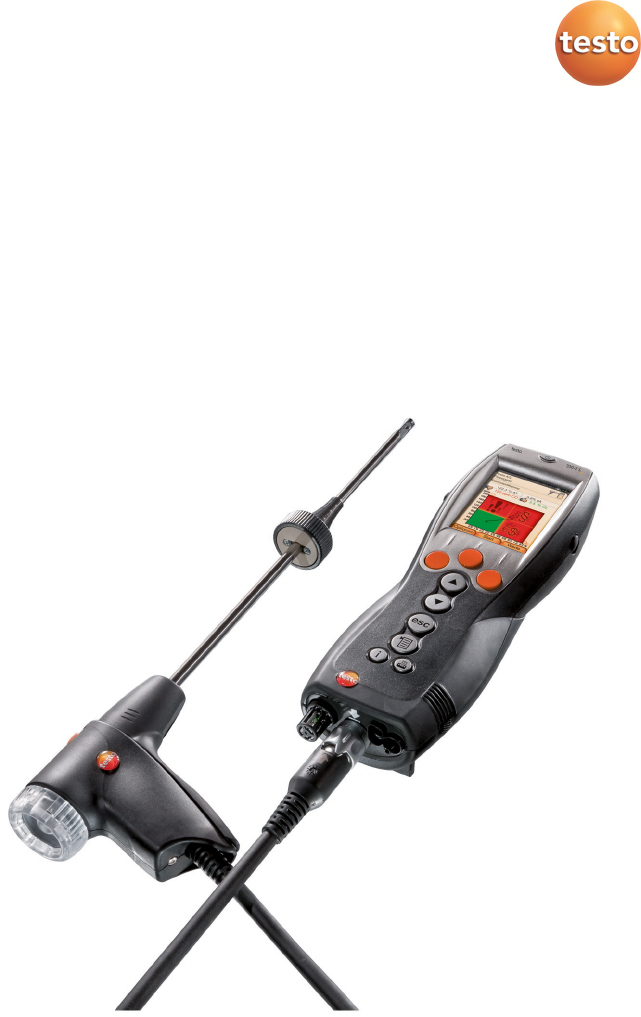
testo 330 · Flue gas analyzer
Instruction manual

2

1 Contents
3
Pos: 1 /TD/Überschr iften/1. Inhalt @ 0\mod_1 177587817070_79.doc x @ 1243 @ 1 @ 1
1 Contents
1 Contents ................................................................................... 3
2 Safety and the environment ...................................................... 7
2.1. About this document ............................................................ 7
2.2. Ensure safety ......................................................................... 8
2.3. Protecting the environment .................................................. 9
3 Specifications ............................................................................ 9
3.1. Use......................................................................................... 9
3.2. Technical data ..................................................................... 11
3.2.1. Examinations and licenses ......................................................................................... 11
3.2.2. Bluetooth® module (option) ....................................................................................... 11
3.2.2.1. Bluetooth®-Type: BlueGiga ......................................................................... 11
3.2.2.2. Bluetooth®-Type: BlueMod+SR ................................................................... 12
3.2.3. Declaration of Conformity ......................................................................................... 15
3.2.4. Measuring ranges and resolution .............................................................................. 17
3.2.5. Accuracy and response time ...................................................................................... 17
3.2.6. Other instrument data ............................................................................................... 19
4 Product description ................................................................. 20
4.1. Case 0516 3300 (accessory) ................................................ 20
4.1.1. Bottom level view ...................................................................................................... 21
4.1.2. Top level view ............................................................................................................ 22
4.2. Case 0516 3301 (accessory) ................................................ 23
4.2.1. Bottom level view ...................................................................................................... 23
4.2.2. Middle level view ....................................................................................................... 24
4.2.3. Top level view ............................................................................................................ 25
4.3. Measuring instrument......................................................... 26
4.3.1. Overview ................................................................................................................... 26
4.3.2. Keypad ....................................................................................................................... 27
4.3.3. Display ....................................................................................................................... 28
4.3.4. Device connections .................................................................................................... 29
4.3.5. Interfaces ................................................................................................................... 29
4.3.6. Components .............................................................................................................. 30
4.3.7. Carrying strap (0440 0581) ........................................................................................ 30
4.4. Modular flue gas probe ....................................................... 31

1 Contents
4
5 First steps ................................................................................ 32
5.1. Commissioning .................................................................... 32
5.2. Getting to know the product .............................................. 32
5.2.1. Mains unit / rechargeable battery ............................................................................. 32
5.2.1.1. Changing the battery.................................................................................. 32
5.2.1.2. Charging batteries ...................................................................................... 33
5.2.1.3. Mains operation ......................................................................................... 33
5.2.2. Connecting probes / sensors ...................................................................................... 34
5.2.3. Switching on .............................................................................................................. 35
5.2.4. Calling up a function .................................................................................................. 35
5.2.5. Entering values .......................................................................................................... 35
5.2.6. Show graphic ............................................................................................................. 36
5.2.7. Printing / saving data ................................................................................................. 37
5.2.8. Remembering data (clipboard) .................................................................................. 37
5.2.9. Confirming an error message ..................................................................................... 37
5.2.10. Switching off .............................................................................................................. 38
5.3. Address/Location ................................................................ 38
5.4. Measurement records ........................................................ 40
5.5. Instrument diagnosis .......................................................... 41
6 Using the product .................................................................... 42
6.1. Performing settings ............................................................. 42
6.1.1. Assigning the right function key ................................................................................. 42
6.1.2. Instrument settings .................................................................................................... 42
6.1.2.1. Readings display ......................................................................................... 42
6.1.2.2. Alarm limits ................................................................................................ 44
6.1.2.3. Units .......................................................................................................... 44
6.1.2.4. Date / time ................................................................................................. 44
6.1.2.5. Energy management .................................................................................. 45
6.1.2.6. Display brightness ...................................................................................... 45
6.1.2.1. Choose measurement type ........................................................................ 45
6.1.2.2. Printer ........................................................................................................ 46
6.1.2.3. Bluetooth® .................................................................................................. 46
6.1.2.4. Language .................................................................................................... 46
6.1.2.5. Country version .......................................................................................... 47
6.1.2.6. Password protection .................................................................................. 47
6.1.3. Sensor settings ........................................................................................................... 48
6.1.3.1. NO2 addition .............................................................................................. 48
6.1.3.2. O2 reference ............................................................................................... 48
6.1.3.3. Sensor protection ....................................................................................... 48
6.1.3.4. Recalibration / adjustment ........................................................................ 49

1 Contents
5
6.1.4. Fuels .......................................................................................................................... 50
6.1.5. Programs ................................................................................................................... 51
6.2. Measuring ........................................................................... 51
6.2.1. Preparing for measurement....................................................................................... 51
6.2.1.1. Zeroing phases ........................................................................................... 52
6.2.1.2. Using the modular flue gas probe .............................................................. 52
6.2.1.3. Configuring the reading display ................................................................. 53
6.2.1.4. Setting location and fuel ............................................................................ 54
6.2.2. Flue gas ...................................................................................................................... 54
6.2.3. Draught-Measurement .............................................................................................. 56
6.2.4. Micro pressure probe ................................................................................................ 57
6.2.5. BImSchV (testo 330-2 LL) ........................................................................................... 57
6.2.6. CO undiluted .............................................................................................................. 58
6.2.7. Smoke No. / HCT ........................................................................................................ 59
6.2.8. Differential pressure .................................................................................................. 60
6.2.9. Differential temperature ........................................................................................... 61
6.2.10. O2 air ......................................................................................................................... 61
6.2.11. Gas flow ..................................................................................................................... 62
6.2.12. Oil flow ...................................................................................................................... 62
6.2.13. CO ambient ................................................................................................................ 63
6.2.14. CO2 ambient .............................................................................................................. 64
6.2.15. Automatic furnaces ................................................................................................... 64
6.2.16. Solid fuel measurement ............................................................................................. 66
6.2.17. Gas pipe tests ............................................................................................................ 67
6.2.17.1. Tightness test 1 .......................................................................................... 67
6.2.17.2. Tightness test 2 .......................................................................................... 68
6.2.17.3. Let By Test ................................................................................................. 69
6.2.17.4. Leak detection ........................................................................................... 69
6.3. Transferring data ................................................................. 70
6.3.1. Report printer ............................................................................................................ 70
6.3.2. PC / Pocket PC ........................................................................................................... 70
7 Maintaining the product ......................................................... 70
7.1. Cleaning the measuring instrument .................................... 70
7.2. Replacing sensors ................................................................ 71
7.3. Recalibrating / adjusting sensors ........................................ 71
7.4. Replacing additional filter ................................................... 72
7.5. Cleaning the modular flue gas probe .................................. 72
7.6. Replacing the probe module ............................................... 73

1 Contents
6
7.7. Changing the thermocouple ............................................... 73
7.8. Condensate container ......................................................... 74
7.9. Checking/replacing the particle filter ................................. 75
8 Tips and assistance .................................................................. 75
8.1. Questions and answers ....................................................... 75
8.2. Accessories and spare parts ................................................ 76
8.3. Updating the instrument software ..................................... 80
Pos: 2 /TD/--- Seitenwechsel --- @ 0\mod_1173774430601_0.docx @ 283 @ @ 1
2 Safety and the environment
7
Pos: 3 /TD/Überschr iften/2. Sicher heit und Umwelt @ 0\mod_11737747 19351_79.docx @ 292 @ 1 @ 1
2 Safety and the environment
Pos: 4 /TD/Überschr iften/2.1 Zu diesem Doku ment @ 0\mod_117377525235 1_79.docx @ 346 @ 2 @ 1
2.1. About this document
Pos: 5 /TD/Sicherhei t und Umwelt/Zu diesem Doku ment/testo 330 Landes version DE, Sprache en (LV- spezifisch!) @ 7\mod_1284034392317_79. docx @ 72238 @ @ 1
This document describes the products testo 330-1 LL and
testo 330-2 LL with the instrument setting Country version |
Germany.
Pos: 6 /TD/Sicherhei t und Umwelt/Zu diesem Doku ment/Verwendung/Ver wendung (Standard) @ 0\mod_1173775068554_79. docx @ 337 @ 5 @ 1
Use
> Please read this documentation through carefully and
familiarize yourself with the product before putting it to use. Pay
particular attention to the safety instructions and warning advice
in order to prevent injuries and damage to the products.
> Keep this document to hand so that you can refer to it when
necessary.
> Hand this documentation on to any subsequent users of the
product.
Pos: 7 /TD/Sicherhei t und Umwelt/Zu diesem Doku ment/Symbole und Schr eibkonventionen/Sy mbole und Schreibkonv. [ testo 330] @ 6\mod_127866 2875713_79.doc x @ 64907 @ 5 @ 1
Symbols and writing standards
Representati
on
Explanation
Warning advice, risk level according to the
signal word:
Warning! Serious physical injury may occur.
Caution! Minor physical injury or damage to the
equipment may occur.
> Apply the specified precautionary measures.
Note: Basic or further information.
testo 330-1 LL
The description only applies for the specified
instrument model testo 330-1 LL or
testo 330-2 LL.
1. ...
2. ...
Action: several steps, the sequence must be
followed.
> ... Action: one step or optional step.
- ... Result of an action.
Menu Elements of equipment , equipment display or
program interface.

2 Safety and the environment
8
Representati
on
Explanation
[OK] Control keys on equipment or control buttons in
program interface.
... | ... Functions / paths within a menu.
“...” Example entries
Pos: 8 /TD/Überschr iften/2.2 Sicher heit gewährleisten @ 0\mod_1173 780783960_79.doc x @ 366 @ 2 @ 1
2.2. Ensure safety
Pos: 9 /TD/Sicherhei t und Umwelt/Sicherhei t gewährleisten/Produ kt bestimmungsge mäß verwenden @ 0\mod_11737 81261848_79.docx @ 38 6 @ @ 1
> Only operate the product properly, for its intended purpose and
within the parameters specified in the technical data. Do not
use any force.
Pos: 10 /TD/Sicherhei t und Umwelt/Sicherhei t gewährleisten/Gerä t bei Beschädigunge n nicht in Betrieb nehmen @ 0\m od_1186985945375_79.doc x @ 2252 @ @ 1
> Do not operate the instrument if there are signs of damage at
the housing, mains unit or feed lines.
Pos: 11 /TD/Sicherhei t und Umwelt/Sicherhei t gewährleisten/K eine Messung an spannungsfü hrenden Teilen @ 0\mod_ 1175692564164_79. docx @ 592 @ @ 1
> Do not perform contact measurements on non-insulated, live
parts.
Pos: 12 /TD/Sicherhei t und Umwelt/Sicherhei t gewährleisten/Nic ht mit Lösungsmittel n lagern @ 0\mod_11756923751 79_79.docx @ 583 @ @ 1
> Do not store the product together with solvents. Do not use any
desiccants.
Pos: 13 /TD/Sicherhei t und Umwelt/Sicherhei t gewährleisten/Nur be schriebene War tungsarbeiten durchführ en @ 0\mod_117569270519 5_79.docx @ 601 @ @ 1
> Carry out only the maintenance and repair work on this
instrument that is described in the documentation. Follow the
prescribed steps exactly. Use only original spare parts
from Testo.
Pos: 14 /TD/Sicherhei t und Umwelt/Sicherhei t gewährleisten/tes to 350/testo 350 Sic herheit @ 5\mod_12613858457 35_79.docx @ 53306 @ @ 1
> Any further or additional work must only be carried out by
authorised personnel. Testo will otherwise refuse to accept
responsibility for the proper functioning of the measuring
instrument after repair and for the validity of certifications.
Pos: 15 /TD/Sicherhei t und Umwelt/Sicherhei t gewährleisten/Nur i n geschlossenen, troc kenen Räumen betreibe n @ 0\mod_1186985797828_79. docx @ 2243 @ @ 1
> Only use the device in closed, dry rooms and protect it from rain
and moisture.
Pos: 16 /TD/Sicherhei t und Umwelt/Sicherhei t gewährleisten/Te mperaturangaben auf Son den/Fühlern @ 0\mod_11756 93293070_79.doc x @ 610 @ @ 1
> Temperatures given on probes/sensors relate only to the
measuring range of the sensors. Do not expose handles and
feed lines to any temperatures in excess of 70 °C unless they
are expressly permitted for higher temperatures.
Pos: 17 /TD/Sicherhei t und Umwelt/Sicherhei t gewährleisten/tes to 330/Sichtbarer Schaden @ 13\mod_1369999619 300_79.docx @ 162534 @ @ 1
> The testo 330 must be checked before commissioning for any
visible damage. Do not commission the testo 330 if there are
signs of damage on the housing, mains unit or supply lines.
Electrical risk.
Pos: 18 /TD/Sicherhei t und Umwelt/Sicherhei t gewährleisten/ vor Ort gültige Sicher heitsbestimmungen beac hten @ 0\mod_118699710732 8_79.docx @ 2298 @ @ 1
> Dangers may also arise from the systems being measured or
the measuring environment: Note the safety regulations valid in
your area when performing the measurements.

3 Specifications
9
Pos: 19 /TD/Sicherhei t und Umwelt/Sicherhei t gewährleisten/Op tion Bluetooth testo 33 0 @ 7\mod_1281422320910_7 9.docx @ 68203 @ 5 @ 1
For products with Bluetooth® (optional)
Changes or modifications that have been made without the explicit
consent of the responsible approval authority, may cause the
retraction of the type approval.
Data transfer may be disturbed by equipment that uses the same
ISM-band, e.g. WLAN, microwave ovens, ZigBee.
The use of radio communication links is not permitted, among
others, in aeroplanes and hospitals. For this reason the following
points must be ensured before entering:
> Switch off the device:
> Isolate the device from any external power sources (mains
cable, external rechargeable batteries, ...).
Pos: 20 /TD/Überschr iften/2.3 Umwelt schüt zen @ 0\mod_1173780843645 _79.docx @ 375 @ 2 @ 1
2.3. Protecting the environment
Pos: 21.1 /TD/Sicher heit und Umwelt/Umwelt sc hützen/Akkus/Bat terien entsorgen @ 0\mod _1175693637007_79.doc x @ 619 @ @ 1
> Dispose of faulty rechargeable batteries/spent batteries in
accordance with the valid legal specifications.
Pos: 21.2 /TD/Sicher heit und Umwelt/Umwelt schü tzen/Produkt entsor gen @ 0\mod_11737803070 72_79.docx @ 357 @ @ 1
> At the end of its useful life, send the product to the separate
collection for electric and electronic devices (observe local
regulations) or return the product to Testo for disposal.
Pos: 22 /TD/Überschr iften/3. Leistungs beschreibung @ 0\mod_11737 74791554_79.doc x @ 301 @ 1 @ 1
3 Specifications
Pos: 23 /TD/Überschr iften/3.1 Verwendung @ 0\mod_1176211016437_ 79.docx @ 695 @ 2 @ 1
3.1. Use
Pos: 24 /TD/Leistungsb eschreibung/Ver wendung/testo 3xx/tes to 330_Verwendung @ 6\ mod_1278664111617_79. docx @ 64971 @ @ 1
The testo 330 is a handheld measuring device for the professional
flue gas analysis of furnace systems:
• Small furnaces (burning oil, gas, wood, coal)
The solid fuel measurement adapter (0600 9765) is
required for measurements on solid fuel systems. The
adapter protects the measuring instrument from harmful
substances (dust, organic compounds, etc.).
• Low-temperature and condensing boilers
• Gas water heaters
These systems can be adjusted using the testo 330 and checked
for compliance with the applicable limit values.
The following tasks can also be carried out with the testo 330:
• Regulating the O2-, CO- and CO2-, NO-, NOx- values in
furnace systems for the purpose of ensuring optimal operation.
• Draught measurement.

3 Specifications
10
• Measuring and regulating the gas flow pressure in gas water
heaters.
• Measuring and optimising the flow and return temperatures of
heating systems.
• CO and CO2 environment measurement.
• Detection of CH4 (methane) and C3H8 (propane).
• The testo 330 can be used for measurements on CHP stations
in accordance with the first German Federal Immission Control
Ordinance (BImschV).
• In principal, the CO sensor can also be used for
measurements on CHP stations. If you should carry out
more than 50 measurements on CHP stations per year,
please contact your nearest testo service centre or send the
testo 330 for checking to testo Service.
A worn NOx filter of the CO sensor can be ordered as a
spare part (order no. 0554 4150) and replaced.
Testo guarantees the functionality of its products
when used in accordance with their intended
purpose. This guarantee does not apply to features
of Testo products in combination with unauthorised
third-party products. Competitor products are not
authorised by Testo.
As is common practice, Testo generally excludes
support, warranty or guarantee claims relating to
functionality that has not been guaranteed by Testo
as part of the product offered. Claims shall also be
excluded in the event of improper use or handling of
the products, e.g. in combination with unauthorised
third-party products.
testo 330 must not be used:
• as a safety (alarm) instrument
testo 330 with Bluetooth® option:
The use of the wireless module is subject to the
regulations and stipulations of the respective country of
use, and the module may only be used in countries for
which a country certification has been granted. The user
and every owner has the obligation to adhere to these

3 Specifications
11
regulations and prerequisites for use, and
acknowledges that the re-sale, export, import etc. in
particular in countries without wireless permits, is his
responsibility.
Pos: 25 /TD/Überschr iften/3.2 Technisc he Daten @ 0\mod_117621108843 7_79.docx @ 704 @ 2 @ 1
3.2. Technical data
Pos: 26 /TD/Leistungsb eschreibung/ Technische Daten/testo 330 Technische Daten/ Zulassungen testo 330 (LV- spezifisch) @ 6\mod_1278665812606_79.doc x @ 65004 @ 33554555555 @ 4
3.2.1. Examinations and licenses
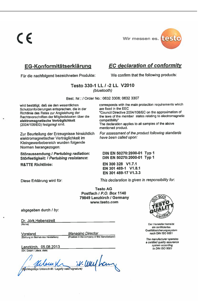
As declared in the certificate of conformity, this product complies
with Directive 2014/30/EC.
3.2.2. Bluetooth® module (option)
3.2.2.1. Bluetooth®-Type: BlueGiga
valid to serial number 2670692
• Bluetooth® type: BlueGiga WT 11 / WT 11i-A (from
October 2013)
• Bluetooth® product note: WT 11
• Bluetooth® identification: B017401 (WT 11) /
B017633 (WT11i-A)
• Bluetooth® company: 10274
Certification
Belgium (BE), Bulgaria (BG), Denmark (DK), Germany (DE),
Estonia (EE), Finland (FI), France (FR), Greece (GR), Ireland (IE),
Italy (IT), Latvia (LV), Lithuania (LT), Luxembourg (LU), Malta (MT),
Netherlands (NL), Austria (AT), Poland (PL), Portugal (PT),
Rumania (RO), Sweden (SE), Slowakia (SK), Slowenia (SI), Spain
(ES), Czech Republic (CZ), Hungary (HU), United Kingdom (GB),
Republic of Cypres (CY).
EFTA countries
Iceland, Liechtenstein, Norway and Switzerland.
Other countries
USA, Canada, Turkey, Colombia, El Salvador, Ukraine, Venezuela,
Ecuador, Australia, New Zealand, Bolivia, Dominican Republic,
Peru, Chile, Cuba, Costa Rica, Nicaragua, Korea
Information of the FCC (Federal Communications
Commission)
This device fulfils part 15 of the FCC-guidelines. Commissioning is
subject to the two following conditions: (1) This device must not

3 Specifications
12
generate any dangerous interferences and (2) this device must be
able to receive interferences, even if these could have undesired
effect on the operation.
Changes
The FCC demands that the user is to be informed that with any
changes and modifications to the device, which have not been
explicitly approved by testo AG, the right of the user to use this
device will become null and void.
3.2.2.2. Bluetooth®-Type: BlueMod+SR
valid from serial number 2670693
• Bluetooth®-Type: BlueMod+SR, Stollmann E+V GmbH
(August 2013)
• Bluetooth® identification ®: B021281
• Bluetooth® company ®: 44784
Certifications
European Certification
Belgium (BE), Bulgaria (BG), Denmark (DK), Germany (DE),
Estonia (EE), Finland (FI), France (FR), Greece (GR), Ireland (IE),
Italy (IT), Latvia (LV), Lithuania (LT), Luxembourg (LU), Malta (MT),
Netherlands (NL), Austria (AT), Poland (PL), Portugal (PT),
Rumania (RO), Sweden (SE), Slowakia (SK), Slowenia (SI), Spain
(ES), Czech Republic (CZ), Hungary (HU), United Kingdom (GB),
Republic of Cypres (CY),.
EFTA countries
Iceland, Liechtenstein, Norway and Switzerland.
Other countries
USA, Canada, Japan, Colombia, El Salvador, Ukraine, Venezuela,
Ecuador, New Zealand, Bolivia, Dominican Republic,
Peru, Chile, Cuba, Costa Rica, Nicaragua, Turkey

3 Specifications
13
USA
Contains Transmitter Module FCC ID: RFRMSR
Product FCC ID: WAF-2016t330
Information from the FCC (Federal Communications Commission)
For your own safety
Shielded cables should be used for a composite interface.
This is to ensure continued protection against radio
frequency interference.
FCC warning statement
This equipment has been tested and found to comply with
the limits for a Class B digital device, pursuant to Part 15 of
the FCC Rules. These limits are designed to provide
reasonable protection against harmful interference in a
residential installation. This equipment generates, uses
and can radiate radio frequency energy and, if not installed
and used in accordance with the instructions, may cause
harmful interference to radio communications. However,
there is no guarantee that interference will not occur in a
particular installation. If this equipment does cause harmful
interference to radio or television reception, which can be
determined by turning the equipment off and on, the user is
encouraged to try to correct the interference by one or
more of the following measures:
• Reorient or relocate the receiving antenna.
• Increase the separation between the equipment and
receiver.
• Connect the equipment into an outlet on a circuit
different from that to which the receiver is connected.
• Consult the dealer or an experienced radio/TV
technician for help.
Caution
Changes or modifications not expressly approved by the
party responsible for compliance could void the user's
authority to operate the equipment. Shielded interface
cable must be used in order to comply with the emission
limits.
Warning
This device complies with Part 15 of the FCC Rules.
Operation is subject to the following two conditions:
(1) this device may not cause harmful interference, and
(2) this device must accept any interference received,
including interference that may cause undesired operation.
3 Specifications
14
Canada
Contains Transmitter Module IC ID: 4957A-MSR
Product IC ID: 6127B -2016T330
This instrument complies with Part 15C of the FCC Rules
and Industry Canada RSS-210 (revision 8). Commissioning
is subject to the following two conditions:
(1) This instrument must not cause any harmful interference
and
(2) this instrument must be able to cope with interference,
even if this has undesirable effects on operation.
Cet appareil satisfait à la partie 15C des directives FCC et
au standard Industrie Canada RSS-210 (révision 8). Sa
mise en service est soumise aux deux conditions suivantes :
(1) cet appareil ne doit causer aucune interférence
dangereuse et
(2) cet appareil doit supporter toute interférence, y compris
des interférences qui provoquerait des opérations
indésirables.
Japan

3 Specifications
15
Pos: 27 /TD/Leistungsb eschreibung/ Technische Daten/testo 330 Technische Daten/Konf ormitätserkläru ng testo 330 bis 2014 @ 6\mod_ 1278667479326_79.doc x @ 65036 @ 3 @ 1
3.2.3. Declaration of Conformity
3 Specifications
16
3 Specifications
17
Pos: 28 /TD/Leistungsb eschreibung/ Technische Daten/testo 330 Technische Daten/ Messbereiche_Genauigkei ten testo330 @ 6\mod_127 8672896705_79.doc x @ 65100 @ 33 @ 1
3.2.4. Measuring ranges and resolution
Parameter Measuring range Resolution
O2 0...21 Vol.% 0.1 vol.%
CO 0...4000 ppm 1 ppm
CO, H2-comp.1 0...8000 ppm 1 ppm
COlow 0...500 ppm 0.1ppm
AmbCO
through flue gas
probe
0...2000 ppm 1 ppm
AmbCO with
probe 0632 3331
0...500 ppm 1 ppm
NO 0...3000 ppm 1 ppm
NOlow 0...300 ppm 0.1 ppm
Draught -9.99...40 hPa 0.01 hPa
∆P 0...300 hPa 0.1 hPa
Temperature -40...1200 °C 0.1°C (-40.0...999.9 °C)
1°C (rest of range)
Efficiency net 0...120 % 0.1 %
Flue gas loss 0...99.9 % 0.1 %
AmbCO2 with
probe 0632 1240
0...1 vol.
0...10000 ppm
-
Gas leak testing
with probe
0632 3330
0...10000 ppm
CH4 / C3H8
-
3.2.5. Accuracy and response time
Parameter Accuracy Response
time
O2 ±0.2 vol.% < 20s (t90)
1 above the sensor protection threshold: Resolution 1 ppm (up to max.
30,000 ppm)

3 Specifications
18
Parameter Accuracy Response
time
CO ±20 ppm (0...400 ppm)
±5% of mv (401...2000 ppm)
±10% of mv (2001...4000 ppm)
< 60s (t90)
CO, H2-comp. ±10 ppm or ±10 % of mv2
(0...200 ppm)
±20 ppm or ±5 % of mv2
(201...2000 ppm)
±10% of mv (2001...8000 ppm)
only testo 330-2:
8000...30000 ppm
(automatic dilution)
< 60s (t90)
COlow ±2 ppm (0…39.9 ppm)
±5 % of mv (rest of range)
< 40s (t90)
AmbCO through
flue gas probe
±10 ppm (0...100 ppm)
±10 % of mv (101….2000 ppm)
< 35s (t90)
AmbCO with
0632 3331
±5 ppm (0...100 ppm)3
±5 % of mv ( >101 ppm)
approx. 35s
(t90)
NO ±2 ppm (0…39,9 ppm)
±5 % of mv (40….2000 ppm)
±10 % of mv (2001...3000 ppm)
< 30s (t90)
NOlow ±2 ppm (0…39,9 ppm)
±5% of mv (rest of range)
< 30s (t90)
Draught4 ±0.02 ppm or ±5% of mv2
(-0.50...0.60 hPa)
± 0.03 hPa (0.61...3.00 hPa)
±1.5 % of mv (3.01...40.00 hPa)
-
2 higher value is valid
3 at 10...30 °C, outside this range additionally ±0.2 % of mv / °C
4 with fine draught measurement option: Measuring range 0...100,
0Pa, resolution 0.1Pa
3 Specifications
19
Parameter Accuracy Response
time
∆P ± 0.5 hPa (0.0...50.0 hPa)
±1 % of mv (50.1...100.0 hPa)
±1.5 % of mv (rest of range)
-
Temperature ± 0.5 °C (0.0...100.0 °C)
±0.5 % of mv (rest of range)
probe
dependent
Efficiency - -
Flue gas loss - -
AmbCO2,
through
0632 1240
±75 ppm + 3 % of mv
(0...5000 ppm)
±150 ppm + 5 % of mv
(5001...10000 ppm)
approx. 35s
(t90)
Gas leak testing
with 0632 3330
- < 2s (t90)
Pos: 29 /TD/Leistungsb eschreibung/ Technische Daten/testo 330 Technische Daten/ weitere Gerätedaten test o 330 @ 6\mod_12786768898 81_79.docx @ 65132 @ 35 @ 1
3.2.6. Other instrument data
Flue gas analyser
Characteristic Values
Storage / and
transport
temperature
-20...50 °C
Operating
temperature
-5...45 °C
Ambient humidity 0…90 % rH, not condensing
Power supply Battery: 3.7 V / 2.6 Ah
Mains unit: 6 V/1.2 A
Protection class IP40
Weight 600 g (excluding battery)
Dimensions 270 x 90 x 65 mm
Memory 500,000 readings
Display Graphic colour display, 240 x 320 pixels
Flue gas
overpressure
max. 50 mbar
Negative pressure max. 80 mbar

4 Product description
20
Characteristic Values
Gas leak testing
probe
visual indication (LED)
audible indication by buzzer
Storage
temperature battery
±0...35 °C
Battery charge time approx. 5-6 h
Battery operation
time
6h (pump on, 20 °C ambient temperature)
Bluetooth® (option) Range < 10 m
Warranty Measuring instrument: 48 months
LL-sensors O2, CO: 48 months
NOlow sensor: 12 months
Other sensors: 24 months
Flue gas probe: 48 months
Thermocouple: 12 months
Battery: 12 months
Further warranty terms: see website
www.testo.com/warranty
Pos: 30 /TD/Überschr iften/4. Produktbesc hreibung @ 0\mod_1173 774846679_79.docx @ 310 @ 1 @ 1
4 Product description
Pos: 31 /TD/Produktb eschreibung/Übersic ht/testo 3xx/tes to 330/testo 330 Beispie l Lieferumfang 0516 3300 @ 15\ mod_1386080504763_7 9.docx @ 179198 @ 233 @ 1
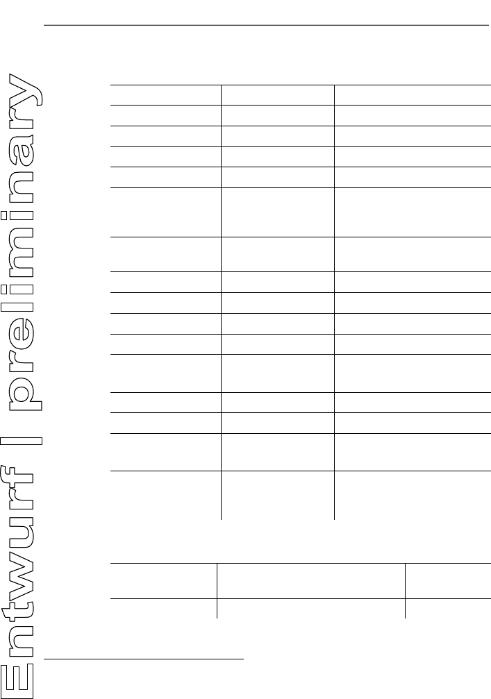
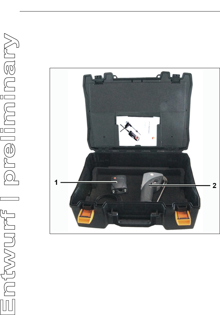
4.1. Case 0516 3300 (accessory)
Recommended for stowing away the measuring instrument and
accessories (example)
4 Product description
21
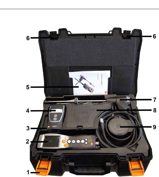
4.1.1. Bottom level view
1 Sealing clip
2 testo 330-1 /-2 LL flue gas analyzer
3 Repository for printer accessories
• Spare batteries for IRDA printer
• 1 roll of spare thermal paper (0554 0568)
4 Repository for printer
• IRDA printer (0554 0549)
• Bluetooth®/IRDA printer (0554 0620)
5. Instruction manual
6 Lock
7 Probes
• Flue gas probe (e.g. 0600 9741)
• Pitot tube for heating check (0635 2050)
8 Large storage compartment
4 Product description
22
• Mains unit for testo 330-1 /-2 LL (0554 1096)
• Differential temperature set (0554 1208)
• Spare dirt filter (0554 0040)
9 Round storage compartment
• Hose connection set with pressure adapter (0554 1203)
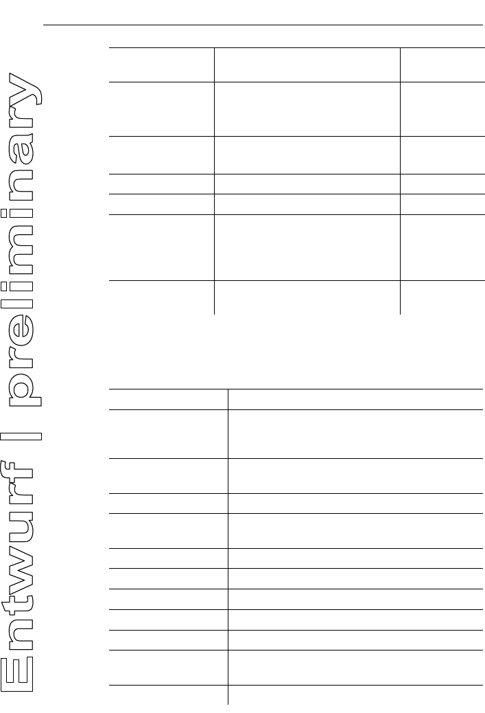
4.1.2. Top level view
1 Soot pump set (0554 0307)
2 Storage compartment
• Fine pressure probe (0638 0330)
3 Storage compartment
• Capillary hose set for fine pressure probe (0554 1215)
• Connecting cable for surface probe (0430 1215)
4 Combustion air temperature probe (0600 9787)
5. Surface temperature probe Type K (0604 0994)
4 Product description
23
Pos: 32 /TD/Produktb eschreibung/Übersic ht/testo 3xx/tes to 330/testo 330 Beispie l Lieferumfang 0516 3301 @ 15\ mod_1386851266100_7 9.docx @ 179983 @ 2333 @ 1
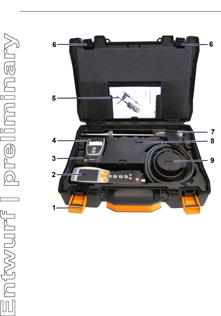
4.2. Case 0516 3301 (accessory)
Recommended for stowing away the measuring instrument and
accessories (example)
4.2.1. Bottom level view
1 Fine pressure probe (0638 0330)
2 testo 308 smoke tester (0632 0308)
4 Product description
24
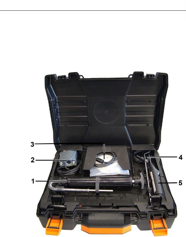
4.2.2. Middle level view
1 Sealing clip
2 testo 330-1 /-2 LL flue gas analyzer
3 Repository for printer accessories
• Spare batteries for IRDA printer
• 1 roll of spare thermal paper (0554 0568)
4 Repository for printer
• IRDA printer (0554 0549)
• Bluetooth® /IRDA printer (0554 0620)
5. Instruction manual
6 Lock
7 Probes
• Flue gas probe (e.g. 0600 9741)

4 Product description
25
• Pitot tube for heating check (0635 2050)
8 Large storage compartment
• Mains unit for testo 330-1 /-2 LL (0554 1096)
• Differential temperature set (0554 1208)
• Spare dirt filter (0554 0040)
9 Round storage compartment
• Hose connection set with pressure adapter (0554 1203)
4.2.3. Top level view
1 Soot pump set (0554 0307)
2 Storage compartment
• Fine pressure probe (0638 0330)
3 Storage compartment
• Capillary hose set for fine pressure probe (0554 1215)
• Connecting cable for surface probe (0430 1215)
4 Product description
26
4 Combustion air temperature probe (0600 9787)
5. Surface temperature probe Type K (0604 0994)
Pos: 33 /TD/Produktb eschreibung/Übersic ht/testo 3xxtest o 330 Übersicht @ 6\mod_127867 9432401_79.doc x @ 65164 @ 2333333352 @ 1
4.3. Measuring instrument
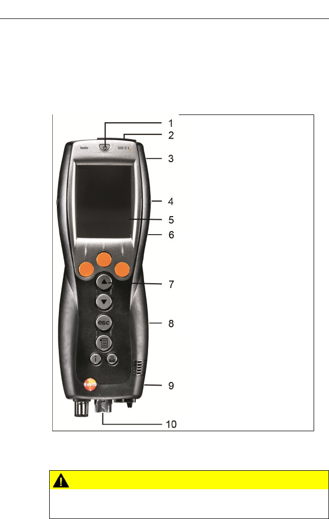
4.3.1. Overview
1 Switch on/off
2 Interfaces: USB, PS2, infrared
CAUTION
Risk of injury from infrared beam!
> Do not direct infrared beam at human eyes!
3 Condensate trap (on rear)
4 Product description
27
4 Fixing eyelets for carrying strap (left and right)
5 Display
6 Magnetic holders (on rear)
WARNING
Magnetic field
May be harmful to those with pacemakers.
> Keep a minimum distance of 15 cm between pacemaker and
instrument.
ATTENTION
Magnetic field
Damage to other devices!
> Keep a safe distance away from products which could be
damaged by the effects of magnetism (e.g. monitors,
computers or credit cards).
7 Keypad
8 Service cover (on rear)
9 Gas outlet
10 Unit connections: flue gas probe, sensor, pressure probe, mains
unit
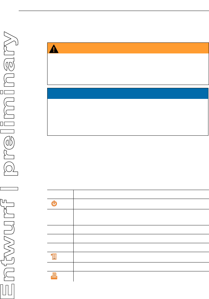
4.3.2. Keypad
Key Functions
[] Switch measuring instrument on / off
[OK]
Example
Function key (orange, 3x), relevant function is shown on
the display
[▲] Scroll up, increase value
[▼] Scroll down, reduce value
[esc] Back, cancel function
[] Open main menu
[ i ] Open instrument diagnosis menu
[] Transmit data to the Testo protocol printer.
4 Product description
28
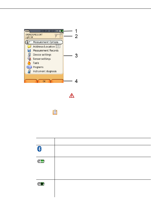
4.3.3. Display
1 Status bar (dark grey background):
• Warning symbol (only if there is a device error, display
of error in instrument diagnosis menu), otherwise:
Instrument designation.
• Symbol (only if data are stored in the temporary
memory).
• Display of date and time.
• Indication of Bluetooth® status, power supply and remaining
capacity of the battery:
Icon Feature
blue symbol = Bluetooth® on,
grey symbol = Bluetooth®off
Battery operation
Indication of remaining capacity of the rech. batt.
by colour and filling degree of the battery symbol
(green = 5-100 %, red = < 5 %)
Mains operation
Indication of remaining capacity of battery: see
above
2 Info field of register tabs: Indication of selected
Address / Location, chosen fuel, chosen measurement type
3 Selection field for functions (chosen function appears against a
white background, unavailable functions are identified by grey
characters) or display of measuring values.
4 Function display for function keys.
4 Product description
29
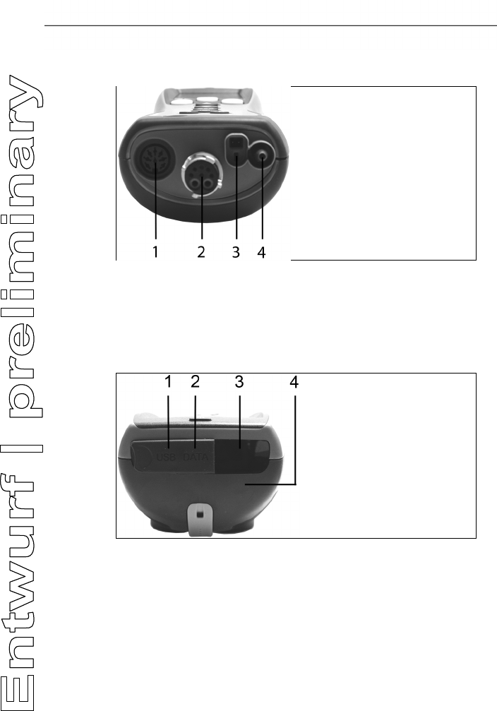
4.3.4. Device connections
1 Probe socket
2 Flue gas socket
3 Mains unit socket
4 Pressure socket
4.3.5. Interfaces
1 USB interface
2 PS2-interface
3 Infrared interface (IrDA)
4 Bluetooth interface (optional)
4 Product description
30
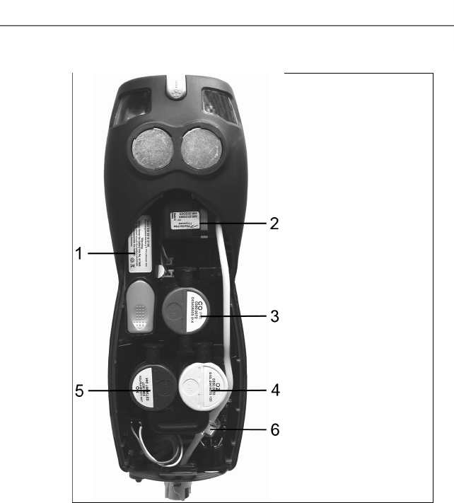
4.3.6. Components
1 Rechargeable battery
2 Measuring gas pump
3 Slot for CO-sensor or COlow-sensor
4 Slot O2-sensor
5 Slot NO-sensor or NOlow-sensor
6 Additional filter
4.3.7. Carrying strap (0440 0581)
To secure the carrying strap:
> Remove the sealing caps from the sides of the housing.
Fix the sealing caps on the inside of the service cover:
1. Place the measuring instrument on its front.
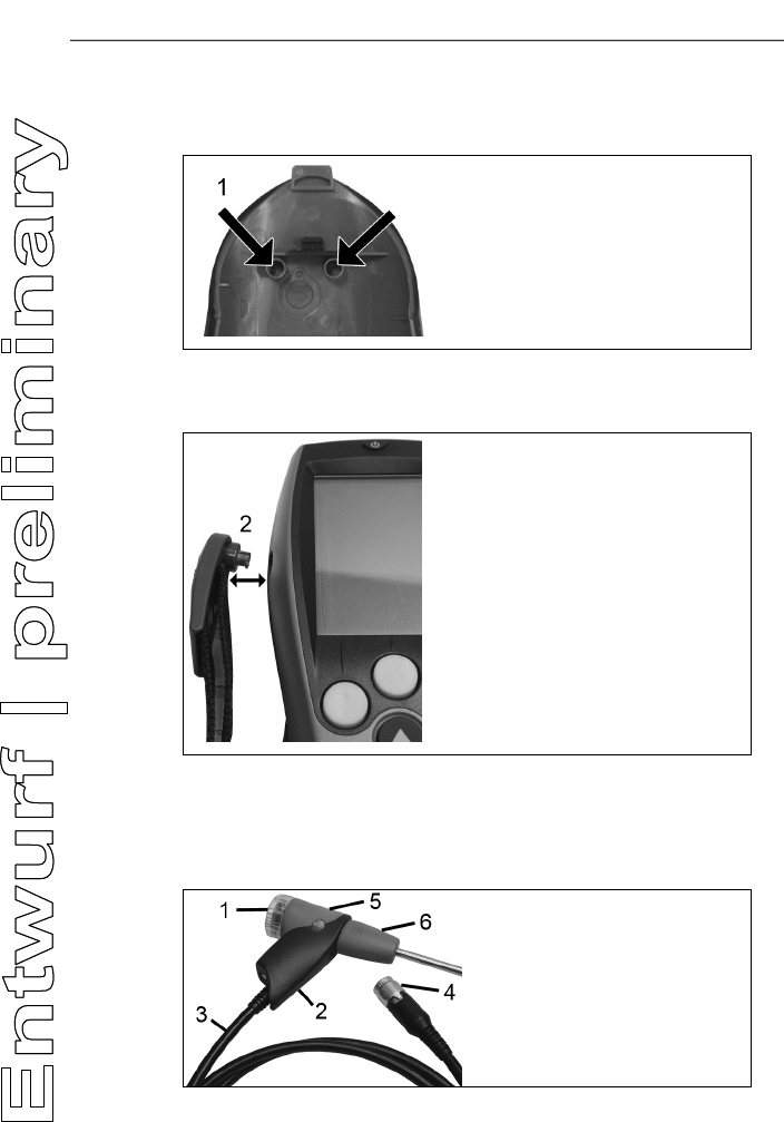
4 Product description
31
2. Pick the service cover up at the markings (arrows) using your
index finger and thumb and press gently to release the lock.
3. Fold up the service cover and remove it.
4. Secure the sealing caps in the two holders on the inside of the
service cover (1).
5. Attach the service cover and engage it in place.
> Engage the carrying strap clip in the fixing eyelets on the sides
of the device. Note the guide groove, the strap must point
"down" (2).
4.4. Modular flue gas probe
1 Removable filter chamber with window and particle filter
2 Probe handle

5 First steps
32
3 Connecting cable
4 Connector plug for measuring instrument
5 Probe module lock release
6 Probe module
Pos: 34 /TD/Überschr iften/5. Erste Schr itte @ 0\mod_1173774895039_ 79.docx @ 319 @ 1 @ 1
5 First steps
Pos: 35 /TD/Überschr iften/5.1 Inbetriebn ahme @ 0\mod_1185342823 812_79.docx @ 1885 @ 2 @ 1
5.1. Commissioning
Pos: 36 /TD/Erste Sc hritte/testo 330/Tes to 330 Inbetriebnahme @ 6\mo d_1278931859503_79.doc x @ 65204 @ @ 1
The measuring instrument is supplied with a rechargeable battery
already fitted.
> Charge the battery fully before using the measuring instrument,
see Charging batteries, page 33.
Pos: 37 /TD/Überschr iften/5.3 Produkt kenn enlernen @ 0\mod_11853 42901015_79.docx @ 1894 @ 2 @ 1
5.2. Getting to know the product
Pos: 38 /TD/Erste Sc hritte/testo 330/test o 330 Produkt kennenlerne n Netzteil_Akkus_B att @ 6\mod_12789320478 63_79.docx @ 65236 @ 3345534 @ 1
5.2.1. Mains unit / rechargeable battery
If the mains unit is connected, the measuring instrument is
automatically powered from the unit.
5.2.1.1. Changing the battery
✓ The measuring instrument must not be connected to a mains
socket via the mains unit. The instrument must be switched off.
Change the rechargeable battery within 3 minutes so that device
settings (e.g. date / time) are not lost.
1. Place the measuring instrument on its front.
2. Remove the service cover: Take hold of it at the markings
(arrows) using the index finger and thumb, press slightly, fold
up and remove.
3. Open the battery lock: Press the grey key and push in direction
of arrow.

5 First steps
33
4. Remove the battery and insert a new rechargeable battery.
Only use the Testo rechargeable battery 0515 0107!
5. Close the battery lock: Press the grey key and push against
direction of arrow until the battery engages.
6. Attach the service cover and engage it in place.
5.2.1.2. Charging batteries
The rechargeable battery can only be charged at an ambient
temperature of ±0...+35 °C. If the battery has been discharged
completely, the charging time at room temperature is approx. 5-6
hrs.
Charging in the measuring instrument
1. Connect the plug of the mains unit to the mains unit socket on
the measuring instrument.
2. Connect the mains plug of the mains unit to a mains socket.
- The charging process will start. The charge condition will be
shown in the display. The charging process will stop
automatically when the battery is fully charged.
Charging in the charging station (0554 1087)
> Refer to the documentation enclosed with the charging station.
Battery care
> Do not fully exhaust rechargeable batteries.
> Store rechargeable batteries only in charged condition and at
low temperatures, but not below 0 °C (best storage conditions
with a charge level of 50-80 %, at an ambient temperature of
10-20 °C, recharge completely before use).
> For longer breaks you should discharge and recharge the
batteries every 3- months. Trickle charging should not exceed 2
days.
5.2.1.3. Mains operation
1. Connect the plug of the mains unit to the mains unit socket on
the measuring instrument.
2. Connect the mains plug of the mains unit to a mains socket.
- The measuring instrument is powered by the mains unit.
- If the measuring instrument is switched off and a rechargeable
battery is inserted, the charging process will start automatically.
Switching the measuring instrument on has the effect of
stopping battery charging and the measuring instrument is then
powered via the mains unit.
5 First steps
34
For longer measurements that are mains-operated, Testo
recommends using a combustion air temperature probe
with connecting cable. Self-heating of the instrument
during mains operation may influence the combustion air
temperature measurement with a mini ambient air probe.
Pos: 39 /TD/Erste Sc hritte/testo 330/test o 330 Produkt kennenlerne n Sonden/Fühler ansch ließen @ 6\mod_127893415 7318_79.docx @ 65268 @ 355 @ 1
5.2.2. Connecting probes / sensors
Probe/sensor detection at the flue gas socket is carried out
continuously. New probes are recognised automatically.
Connect a probe to the probe socket before switching on
the measuring instrument or start sensor detection
manually after changing the probe: [Options] → Sensor
detection.
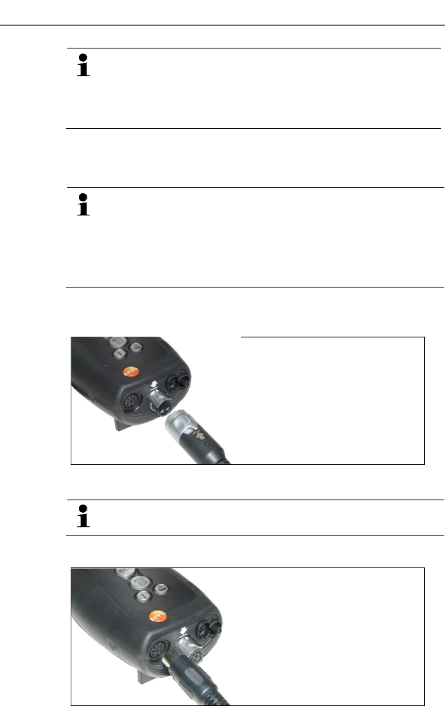
Connecting flue gas probes / gas pressure adapters /
temperature adapters
> Insert the connector plug into the flue gas socket and lock by
slightly turning it clockwise (bayonet lock).
There must be no more than one extension lead (0554
1201) between measuring instrument and flue gas probe.
Connecting other sensors
> Insert the connector plug of the probe into the probe socket.
5 First steps
35
Pos: 40 /TD/Erste Sc hritte/testo 330/test o 330 Produkt kennenlerne n Basisfunktionen ( LV-spezifisch) @ 6\mod_1278935326903_79. docx @ 65300 @ 3535533333 @ 1
5.2.3. Switching on
> press [] .
- The start screen is displayed (duration: about 5 s).
- If the voltage supply was interrupted for a longer period: The
menu Date / Time is opened.
- The pressure sensors are set to zero.
- There is a device error: The Error Diagnosis is displayed.
- The menu Measurements is displayed.
5.2.4. Calling up a function
1. Select function: [▲], [▼].
- The chosen function appears in a frame.
2. Confirm selection: [OK].
- The chosen function is opened.
5.2.5. Entering values
Some functions require values (numbers, units, characters) to be
entered. Depending on the function that is chosen, the values are
entered via either a list field or an input editor.
List field
1. Select the value to be changed (numerical value, unit): [▲],
[▼], [◄], [►] (depending on the selected function).
2. Press [Edit] .
3. Set value: [▲], [▼], [◄], [►] (depending on the selected
function).
4. Confirm the entry: [OK].
5. Repeat steps 1 and 4 as required.
5 First steps
36
6. Save the entry: [Finished].
Input editor
1. Select the value to be changed (character): [▲], [▼], [◄], [►].
2. Accept value: [OK].
Options:
> Toggle between upper / lower case characters:
Select Ι← ABC→&$/ →Ι : [▲], [▼] → [ABC→&$/].
> Position the cursor in the text:
Select Ι← ABC→&$/ →Ι : [▲], [▼] → [Ι←] or
[→Ι].
> Delete character before or after the cursor:
Select ← next → : [▲], [▼] → [←] or [→].
3. Repeat steps 1 and 2 as required.
4. Save the entry: Select ← next → : [▲], [▼] → [Next].
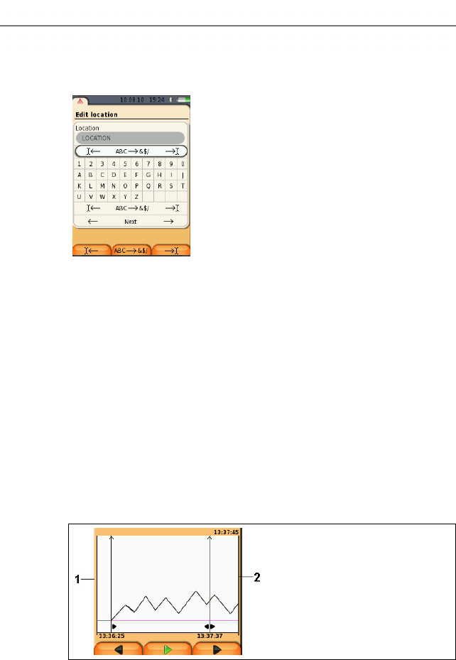
5.2.6. Show graphic
1 Current measuring value
2 End time of the displayed period.
The time is not displayed if no measuring value was recorded for
this period.
5 First steps
37
5.2.7. Printing / saving data
Data are printed out via the function key [] or the menu Options.
Data are saved via the menu Options. The menu Options is
accessed via the left function key and is available in many different
menus.
Assignment of the right function key with the function Save or
Print, see Assigning the right function key page 42 .
Only measuring values, which have a display field in the
measurement view assigned, will be saved / printed out.
The measurement data can be printed out parallel to the
saving process, while a measurement program is running.
To be able to transmit data via infrared or Bluetooth interface to a
report printer, the printer to be used must have been activated, see
Activating the printer:, page 46.
Graph charts can be printed out using the Bluetooth® /
IRDA printer 0554 0620.
5.2.8. Remembering data (clipboard)
With the help of the clipboard measuring results from various
measurement types can be combined to a common record, which
can then be printed out (see above). Data are saved to the
clipboard via the menu Options and the command Clipboard.
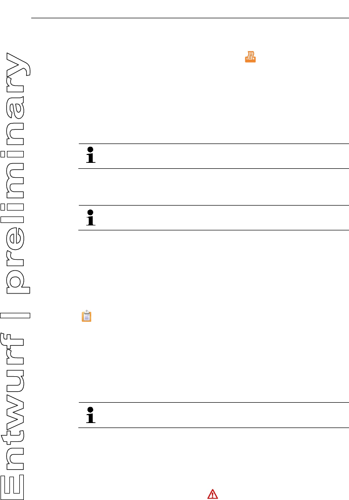
If there are data in the clipboard, the status bar shows the symbol
.
If there are data in the clipboard and the command Print is
triggered, all data in the clipboard will be printed out.
Only one set of measuring data can be recorded per measurement
type (e.g. Flue Gas or Draught). Repetitive saving of test data of
one measurement type overwrites the previously saved data. When
changing the measurement place or the fuel, the clipboard is
deleted.
> [Options] → Delete clipboard: Any data saved to the
clipboard is deleted.
5.2.9. Confirming an error message
If an error occurs, an error message is shown in the display.
> Confirming an error message: [OK].
Errors which have occurred and have not yet been rectified are
indicated by a warning symbol ( ) in the header.

5 First steps
38
Not yet rectified error messages can be displayed in the menu
Error Diagnosis, see Instrument diagnosis, page 41.
5.2.10. Switching off
Unsaved measuring values will be lost when the flue gas
analyser is switched off.
> Press [] .
- Possibly: The pump starts and the sensors are rinsed until the
switch-off thresholds (O2 > 20 %, other measurement
parameters < 50 ppm) are reached. The maximum rinsing
period is 3 minutes.
- The measuring instrument switches off.
Pos: 41 /TD/Erste Sc hritte/testo 330/test o 330 Produkt kennenlerne n Ordner_Messorte @ 6\ mod_1278942335615_79. docx @ 65332 @ 255555555 @ 1
5.3. Address/Location
All measuring values can be saved under the currently active
location. Measuring values that have not been saved are lost when
the measuring instrument is switched off!
Addresses and locations can be created, edited, copied and
enabled. Addresses and locations (incl. protocols) can be deleted.
Call up function:
> [] → Address/Location → [OK].
There are various options for opening address.
1. Edit search setting: [Edit].
2. Select search setting: [▲], [▼] → [OK].
Possible settings:
• Show all: All address/location are displayed.
• Search: A search text only brings up address/location that
contain characteristics of the search text.
• Filter: Individual letters or numbers can be selected. All data
beginning with the relevant letter/number is displayed.
The initial letter is the determining factor for the filter
function, and this can only be selected individually. The
search function can also be used to find a series of several
letters within the address!
3. Carry out search according to search setting: [Search]
Show all
1. Select address: [▲], [▼].
2. Show details: [Details].
5 First steps
39
3. Enable a location: select the location → [OK].
- The location is activated.
> Open measurements menu: press [OK] again.
Search
1. Edit search criteria: [►] → [Edit].
2. Select search criteria: [▲], [▼] → [OK].
Possible options:
• Contact person
• Address
• Town/city
• Postcode
• Street
- The selected criterion is displayed.
3. Call up entry field for search text: [►] or [▼]
> Enter search text → [Finished]
Do not use the special character * as a placeholder.
Filter
1. Edit search criteria: [Edit].
2. Select search criteria: [▲], [▼] → [OK].
Possible options:
• Contact person
• Address
• Town/city
• Postcode
• Street
- The selected criterion is displayed.
3. Enable tab: [▼]
4. Select the required tab: [▲], [▼] and sometimes [◄], [►]→
[Filter].
- The search result for the relevant letter or number is displayed.
Create a new measuring location:
A location is always created under an address.
1. Select the address in which the location is to be created.
2. [Options] → New/Location → [OK].
3. Enter values or make settings.
4. Finalise the entry: [Finished].

5 First steps
40
Other location options:
> [Options] → Edit location: make changes to an existing
location.
> [Options] → Copy location: make a copy of an existing
location in the same address.
> [Options] → Delete location: delete an existing location.
Create new address:
1. [Options] → New address → [OK].
2. Enter values or make settings.
3. Finalise the entry: [Finished].
Other address options:
• Edit address: make changes to an existing folder.
• Copy address: make a copy of an existing folder.
• Delete address: delete an existing folder, including the
locations created therein.
• Delete All addresses: delete all existing folders, including the
locations created in them.
Pos: 42 /TD/Erste Sc hritte/testo 330/test o 330 Produkt kennenlerne n Protokolle @ 6\mod_1279 004185634_79.doc x @ 65363 @ 1555 @ 1
5.4. Measurement records
Calling up the function:
> [] → Measurement Records → [OK].
There are various options for opening protocols, see
Address/Location, page 38
Displaying a record:
1. Choose the required record from the detailed view.
2. Print [Data].
Printing all records for a location:
1. Select measuring location: [▲], [▼]
2. Start printout: [].
- All records for the location are printed out.
Options:
> [Options] → Show Graphic: Display saved record data as
graphic.
> [Options] → Print Data: Transmit data of the chosen record to
a record printer.
> [Options] → Delete Record: Delete the chosen record.

5 First steps
41
> [Options] → Number of Lines: Change the number of
measuring values per display page.
> [Options] → Delete all Records: Delete all saved records for a
location.
Pos: 43 /TD/Erste Sc hritte/testo 330/test o 330 Produkt kennenlerne n Gerätediagnose @ 6\ mod_1279004297026_79. docx @ 65394 @ 25555 @ 1
5.5. Instrument diagnosis
Important operating values and instrument data are displayed. A
gas path check (testo 330-2 LL) can be carried out. The status of
the sensors and any device errors not yet rectified can be
displayed.
Calling up the function:
> [] → Instrument Diagnosis → [OK].
or
> [ i ].
Carrying out a gas path check (testo 330-2 LL)
1. Gas Path Check → [OK]
2. Place the black sealing cap on the tip of the flue gas probe.
- The pump flow is displayed. If the volumetric flow rate is less
than 0.02 l/min, the gas paths are not leaking.
3. End of check: [OK].
Viewing device errors:
> Error Diagnosis → [OK].
- Unrectified errors are displayed.
> View next / previous error: [▲], [▼].
View sensor diagnosis:
1. > Sensor Diagnosis → [OK].
2. Select sensor. [▲], [▼].
- The status of the sensor is indicated by a lamp.
A sensor is able to recover. It is therefore possible that the
sensor status indication changes from yellow to green or
from red to yellow.
View instrument information:
> Device Information → [OK].
- Information is displayed.

6 Using the product
42
Pos: 44 /TD/Überschr iften/6. Produkt ver wenden @ 0\mod_117377492855 4_79.docx @ 328 @ 3 @ 1
6 Using the product
Pos: 45 /TD/Überschr iften/6.1 Einstellun gen vornehmen @ 0\mod_11845 84321421_79.doc x @ 1863 @ 3 @ 1
6.1. Performing settings
Pos: 46 /TD/Produkt ver wenden/testo 330/tes to 330 Rechte Funktions taste belegen @ 6\mod_127928 3093786_79.doc x @ 67168 @ 3 @ 1
6.1.1. Assigning the right function key
The right function key can have a function from the Options menu
assigned to it. The menu Options is accessed via the left function
key and is available in many different menus. This assignment is
only valid for the currently opened menu / the opened function.
✓ A menu / function is opened in which the Options menu is
displayed on the left function key.
1. Press [Options] .
2. Select option: [▲], [▼].
Depending on the menu / function from which the Options menu
was opened, the following functions are available.
3. Assign the selected function to the right function key: Press
[Config. Key].
Pos: 47 /TD/Produkt verwenden/testo 350 neu/te sto 350 Geräteeinste llungen CU/testo 350 Ger äteeinstellungen_ Ueberschrift @ 5\ mod_1266322627982_79.doc x @ 58663 @ 3 @ 1
6.1.2. Instrument settings
Pos: 48 /TD/Produkt verwenden/testo 330/tes to 330 Geräteeinstel lungen aufrufen @ 6\mod_1 279008333499_79.doc x @ 65426 @ @ 1
It is assumed that the contents of the chapter First steps
(see First steps, page 32) are known.
Calling up a function:
> [] → Device Settings.
Pos: 49 /TD/Produkt verwenden/testo 330/tes to 330 Messwertanzeige D E, Sprache en (LV-spezi fisch!) @ 7\mod_1284035 052608_79.docx @ 72271 @ 4555 @ 1
6.1.2.1. Readings display
The parameters / units and the display representation (number of
readings displayed per display page) can be set.
The settings are only valid for the currently chosen measurement
type, which is indicated by the symbol in the info field.
Total overview of selectable parameters and units (available
selection depends on the chosen measurement type):
Display Parameter
FT Flue gas temperature
AT Combustion air temperature
ltemp Instrument temperature
Pump Pumping capacity

6 Using the product
43
Display Parameter
O2 Oxygen
CO2 Carbon dioxide
CO Carbon monoxide
uCO Carbon monoxide undiluted
NO Nitrogen monoxide
NOx Nitrogen oxide
λ Air ratio
amCO Ambient carbon monoxide
amCO2 Ambient carbon dioxide
O2ref Oxygen reference
Edrft external draught (micro pressure probe)
E-∆P external differential pressure (micro pressure
probe)
qAnet Flue gas loss without consideration of the heat
value range
qAgr. Flue gas loss under due consideration of the heat
value range
η+ Efficiency under due consideration of the heat
value range
η Efficiency without consideration of the heat value
range
Dew/a Flue gas dew point temperature
Calling up the function:
> [] → Instrument Settings → [OK] → Readings Display →
[OK]
Changing parameter / unit in a line:
1. Select the line where you want to position the selected
measurement parameter: [▲], [▼] → [Edit]
2. Select the parameter: [▲], [▼] → [OK]
3. Select the unit: [▲], [▼] → [OK]
4. Save changes: [OK]
- The measurement parameter is now in the selected position on
the reading display.

6 Using the product
44
Options:
> [Options] → Number of Lines: Change the number of
measuring values per display page.
> [Options] → Insert Empty Lines: Insert the empty line before
the selected line.
> [Options] → Delete Line: Delete the selected line.
> [Options] → Factory Setting: Reset the readings display to
factory setting
Pos: 50 /TD/Produkt verwenden/testo 330/tes to 330 Alarschwellen @ 6\ mod_1279021018511_79. docx @ 65490 @ 45 @ 1
6.1.2.2. Alarm limits
Alarm limits can be set for several display parameters. An audible
alarm signal is triggered when the alarm limit is reached.
Calling up the function:
> [] → Instrument Settings → [OK] → Alarm Limits → [OK]
Switching alarm signals on / off, changing alarm limits:
1. Select function or parameter: [▲], [▼] → [Edit].
2. Set parameter: [▲], [▼] and partly [◄], [►] → [OK].
3. Save changes: [Finished].
> Reset the enabled value to the factory setting: [Standard].
Pos: 51 /TD/Produkt verwenden/testo 330/tes to 330 Einheiten @ 6\mod_127 9022297845_79.doc x @ 65521 @ 45 @ 1
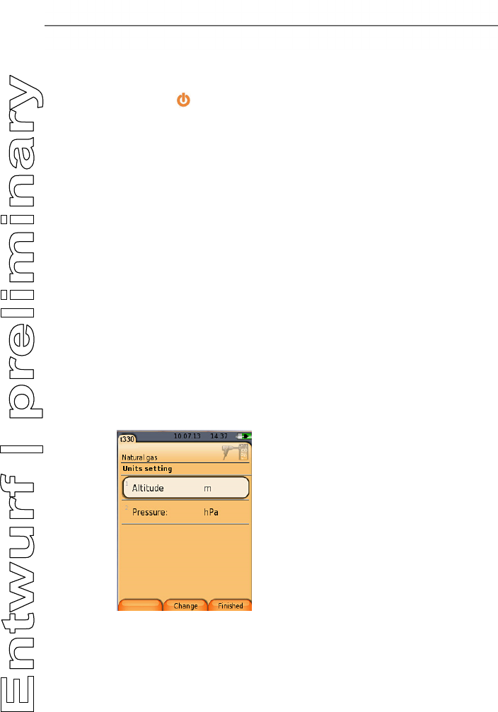
6.1.2.3. Units
The units used for parameters in configuration menus can be set.
Calling up the function:
> [] → Instrument Settings → [OK] → Units → [OK]
Adjustable units
Parameter Unit
Altitude m, ft
Pressure mbar, hPa
1. Select the line: [▲], [▼]→ [Edit].
2. Select the unit to be changed: [▲], [▼] → [OK].
3. Confirm the entry: [Finished].
Pos: 52 /TD/Produkt verwenden/testo 330/tes to 330 Datum_Uhrzeit @ 6\m od_1279023342203_79.d ocx @ 65553 @ 45 @ 1
6.1.2.4. Date / time
Date, time mode and time can be set.
Calling up the function:
> [] → Instrument Settings → [OK] → Date/Time → [OK]

6 Using the product
45
Setting date/time:
1. Select parameter: [◄], [▲], [▼] → [Edit].
2. Set parameter: [▲], [▼] and partly [◄], [►] → [OK].
3. Save changes: [Save].
Pos: 53 /TD/Produkt verwenden/testo 330/Test o 330 Energieverwaltu ng @ 6\mod_1279023810346_ 79.docx @ 65585 @ 45 @ 1
6.1.2.5. Energy management
Automatic instrument shutdown (Auto-Off) and switching off of the
display light in battery operation can be set.
Calling up the function:
> [] → Instrument Settings → [OK] → Energy Management
→ [OK]
Making settings:
1. Select function or parameter: [▲], [▼] → [Edit].
2. Set parameter: [▲], [▼] and partly [◄], [►] → [OK].
3. Save changes: [Finished].
Pos: 54 /TD/Produkt verwenden/testo 330/tes to 330 Display @ 6\mod_12790256 03358_79.docx @ 65617 @ 4 @ 1
6.1.2.6. Display brightness
The intensity of the display illumination can be set.
Calling up the function:
> [] → Instrument Settings → [OK] → Display Brightness →
[OK]
Performing settings
> Set parameter: [◄], [►] → [OK].
Pos: 55 /TD/Produkt verwenden/testo 330/tes to 330 Auswahl_Messar t @ 15\mod_1386331304928 _79.docx @ 179731 @ 45 @ 1
6.1.2.1. Choose measurement type
Individual measurement types can be shown or hidden. These are
displayed or hidden accordingly under Measurement options.
Call up function:
> [] → Device settings → [OK] → Choose measurement
type → [OK].
Show or hide measurement types:
1. Select measurement type: [▲], [▼]
2. Enable / disable measurement type: [] (enabled), []
(disabled)
3. Save selection: [Finished].
6 Using the product
46
Pos: 56 /TD/Produkt verwenden/testo 330/Test o 330 Drucker @ 6\mod_12790 25854485_79.doc x @ 65649 @ 455 @ 1
6.1.2.2. Printer
The headers (lines 1-3) and the footers for the printout can be set.
The printer that is used can be activated.
Calling up the function:
> [] → Instrument Settings → [OK] → Printer → [OK]
Activating the printer:
The printer 0554 0543 can only be selected after the
Bluetooth®-interface has been activated, see
Bluetooth®, page 46.
1. Select Printer → [OK].
2. Select the printer: [▲], [▼] → [OK].
- The printer is activated and the menu Printer is opened.
Configuring the print text:
1. Print text → [OK].
2. Select function: [▲], [▼] → [Edit].
> Enter values for Line 1, Line 2, Line 3 and the Footnote
> Print out system data and/or customer data: []
3. Save the entry: select [Finished].
Pos: 57 /TD/Produkt verwenden/testo 330/tes to 330 Bluetooth @ 6\mod_127 9026530745_79.doc x @ 65681 @ 45 @ 1
6.1.2.3. Bluetooth®
This menu is only available if the instrument is equipped with
Bluetooth. The Bluetooth module can be switched on / off.The relay
can now be tested.
Calling up the function:
> [] → Instrument Settings → [OK] → Bluetooth → [Edit].
Making settings:
> Set parameter → [OK].
Pos: 58 /TD/Produkt verwenden/testo 330/tes to 330 Sprache @ 6\mod_12790 26896670_79.doc x @ 65713 @ 45 @ 1
6.1.2.4. Language
The menu language can be set. The number of available
languages depends on the activated country version, see Country
version, page 47.
Calling up the function:
> [] → Instrument Settings → [OK] → Language → [OK]
6 Using the product
47
Activating the language:
> Select the language → [OK].
see Country version, page 47
Pos: 59 /TD/Produkt verwenden/testo 330/tes to 330 Landesversion @ 6\ mod_1279026924467_79. docx @ 65745 @ 45 @ 1
6.1.2.5. Country version
Changing the country version may alter the basis for calculation
and therefore also the displayed measurement parameters, fuels,
fuel parameters and calculation formulas.
The selection of the country version influences the menu languages
that can be enabled.
For information concerning the assignment table, the basis for
calculation and the country version, see www.testo.com/download-
center.
Calling up the function:
> [] → Instrument Settings → [OK] → Country Version →
[OK]
This action can be password protected. A password is
specified in the menu Password Protection, see
Password protection, page 47.
Possibly:
> Enter the password: [Enter] → Enter password → [Next] →
[OK].
Setting the country version:
1. Select the country version: [▲], [▼] → [OK].
2. Confirm the confirmation request: Yes → [OK]
- The system is restarted.
Pos: 60 /TD/Produkt verwenden/testo 330/tes to 330 Passwortschu tz @ 6\mod_1279028157194_ 79.docx @ 65809 @ 45 @ 1
6.1.2.6. Password protection
The password protection is only valid for functions identified by the
following symbol: or .
Password protection can be activated / deactivated, the password
can be changed.
To deactivate the password protection change the password to
0000 (factory setting).
Calling up the function:
> [] → Instrument Settings → [OK] → Password Protection
→ [OK]
Possibly:

6 Using the product
48
> Enter the currently valid password:
[Enter] → Enter password → [Next] → [OK].
Changing the password:
1. [Edit].
2. Enter the new password → [Next].
3. [Edit].
4. Enter the new password again to confirm → [Next].
5. Save changes: [Finished].
Pos: 61 /TD/Produkt verwenden/testo 330/tes to 330 Sensoreinstel lungen @ 6\mod_127909571 3244_79.docx @ 65843 @ 345454 545 @ 1
6.1.3. Sensor settings
6.1.3.1. NO2 addition
The NO2 addition parameter can be set.
The setting of the NO2-addition can be password protected, see
Password protection, page 47.
Calling up the function:
> [] → Sensor Settings → NO2 Addition → [Edit].
Possibly:
> Enter the password: [Enter] → Enter password → [Next] →
[OK].
Setting the NO2 addition:
> Set parameter → [OK].
6.1.3.2. O2 reference
The O2 reference value can be set.
The setting of the O2 reference value can be password protected,
see Password protection, page 47.
Calling up the function:
> [] → Sensor Settings → O2 Reference→ [Edit].
Possibly:
> Enter the password: [Enter] → Enter password → [Next] →
[OK].
Setting the O2 reference:
> Set parameter → [OK].
6.1.3.3. Sensor protection
Protection limits can be set to protect the sensors against overload.
Sensor protection switch-off is available for the following sensors:
CO, NO.
6 Using the product
49
The sensor protection is activated when the threshold is exceeded.
• testo 330-1 LL: Switch-off.
• testo 330-2 LL: Dilution, if exceeded again: Switch-off.
To deactivate sensor protection the thresholds must be set to 0
ppm.
Calling up the function:
> [] → Sensor Settings → Sensor Protection → [OK].
Setting sensor protection thresholds:
1. Select parameter: [Edit].
2. Set parameter → [OK].
3. Save changes: [Finished].
6.1.3.4. Recalibration / adjustment
CO and NO sensors can be recalibrated and adjusted.
For recalibration / adjustment Testo recommends the use of the
calibration adapter 0554 1205.
If obviously unrealistic readings are displayed, the sensors
should be checked (calibrated) and, if required, adjusted.
Have the recalibration / adjustment carried out by a
qualified service centre approved by Testo.
Adjustments made with low gas concentrations can lead to
accuracy deviations in the upper measuring ranges.
Calling up the function:
> [] → Sensor Settings → Recalibration → [OK].
Possibly:
> Enter the password: [Enter] → Enter password → [Next] →
[OK].
- Gas zeroing (30 s).
Performing recalibration / adjustment:
WARNING
Dangerous gases
Danger of poisoning!
> Observe safety regulations / accident prevention regulations
when handling test gas.
> Use test gases in well ventilated rooms only.
1. Connect the calibration adapter to the flue gas socket.
2. Select the parameter: [▲], [▼] → [OK].

6 Using the product
50
3. [Edit] → Enter the test gas concentration (nominal value).
4. Attach the connecting line of the test gas bottle to the
calibration adapter.
5. Apply test gas to the sensor.
6. Start recalibration: [Start].
7. Accept the nominal value once the actual value is stable
(adjustment): [OK].
-or-
Abort (no adjustment): [esc].
8. Save changes: [Finished].
Pos: 62 /TD/Produkt verwenden/testo 330/tes to 330 Brennstoffe @ 6\ mod_1279096803274_79. docx @ 65875 @ 3555 @ 1
6.1.4. Fuels
The fuel can be selected. The fuel-specific coefficients and limits
can be set.
Apart from the pre-configured fuels, 10 more customer specific
fuels can be configured. Fuel parameter, see
www.testo.com/download-center (registration required).
In order to maintain the measuring accuracy of the
instrument one must choose or configure the correct fuel.
Correct representation of measuring results is only assured
if the threshold values for the ideal range of the
corresponding measurement task have been set correctly.
The pre-set threshold values are typical values for the
selected system type and the chosen type of fuel.
Calling up the function:
> [] → Fuels → [OK].
Activating fuels:
> Select the fuel → [OK].
- The fuel is activated and the main menu is opened.
Setting coefficients:
1. Select the fuel → [Coeff.].
2. Select the coefficients: [Edit].
Possibly:
> Enter the password: [Enter] → Enter password → [Next] →
[OK].
3. Set values → [OK].
4. Save changes: [Finished].
6 Using the product
51
Setting limits:
1. Select limit → [Edit].
2. Set values → [OK].
3. Save changes: [Finished].
Pos: 63 /TD/Produkt verwenden/testo 330/tes to 330 Programme @ 6\mod_12790 96840212_79.doc x @ 65907 @ 355 @ 1
6.1.5. Programs
Five measuring programs for different measurement types can be
configured and activated. The measuring programs serve the
purpose of saving and representing measuring sequences. After
the end of the measuring process the readings of a measuring
program are automatically saved in a record.
Only one measuring program can be activated in the instrument.
Calling up the function:
> [] → Programs → [OK].
Activating / deactivating a program:
> Select the program: [▲], [▼] → [Enable] or [Disable].
- When activating a program: The program is activated and the
measurement type matching the program is opened.
Configuring the program:
The measuring cycle takes 1s and cannot be changed.
An activated program cannot be configured.
1. Select the program: [▲], [▼] → [Edit].
2. Select parameters program name, measurement type, gas
phase: [▲], [▼] → [Edit].
3. Set parameters or enter values: [▲], [▼] and partly [◄], [►]→
[OK].
4. Save changes: [Finished].
Pos: 64 /TD/Überschr iften/6.3 Messungen durc hführen @ 0\mod_118458 4650078_79.doc x @ 1872 @ 2 @ 1
6.2. Measuring
Pos: 65 /TD/Produkt verwenden/testo 330/tes to 330 Messung vorbereit en @ 6\mod_1279108120992_ 79.docx @ 65971 @ 3455545544 @ 1
6.2.1. Preparing for measurement
It is assumed that the contents of the chapter First steps
(see First steps, page 32) are known.
6 Using the product
52
6.2.1.1. Zeroing phases
Measuring the ambient air temperature (AT)
If no combustion air temperature probe is connected, the
temperature measured by the thermocouple of the flue gas probe
during the zeroing phase is used as the combustion air
temperature. All dependent parameters are calculated using this
value. This method of measuring combustion air temperature is
sufficient for systems dependent on ambient air. However, ensure
that the flue gas probe is near the intake duct of the burner during
the zeroing phase.
If a combustion air temperature probe is connected, the combustion
air temperature is measured continuously via this probe.
Gas zeroing
When the instrument is switched on the measurement menu is
opened and the gas sensors are zeroed.
testo 330-1 LL: The flue gas probe must be in the open air
during the zeroing phase!
testo 330-2 LL: The flue gas probe can be in the flue gas
duct even during the zeroing phase, if a separate VT-
sensor is plugged in.
Draught / pressure zeroing
The pressure sensors are zeroed when a pressure measuring
function is called up.
testo 330-1 LL: The flue gas probe must be in the open air
during the zeroing phase / the instrument must not be
pressurised during zeroing!
testo 330-2 LL: The flue gas probe can be in the flue gas
duct even during the zeroing phase, if a separate VT-
sensor is plugged in. The pressure socket of the instrument
must be free (i.e. unpressurized, not closed).
6.2.1.2. Using the modular flue gas probe
Checking the thermocouple
The thermocouple of the flue gas probe must not lie against the
probe cage.
> Check before use. Bend the thermocouple back if necessary.

6 Using the product
53
Aligning the flue gas probe
The flue gas must be able to flow freely past the thermocouple.
> Align the probe by turning it as required.
The tip of the probe must be in the hot spot of the flue gas flow.
> Align the flue gas probe in the flue gas duct so that the tip is in
the hotspot (area of the highest flue gas temperature). As a
visual aid, the display shows the current temperature with a
green bar. The red marking indicates the maximum measured
temperature during the hotspot search. If the symbol
appears, the temperature is outside the measuring range of the
flue gas probe.
The measuring value of the red marking and the
symbol can only be cancelled by restarting the flue gas
menu.
6.2.1.3. Configuring the reading display
Only those parameters and units, which are activated in the reading
display, appear in the reading display, the saved measurement
protocols and the record printouts.
> Before performing measurements set up the reading display in
such a way, that the required parameters and units are
activated, see Fehler! Verweisquelle konnte nicht gefunden
werden., page Fehler! Textmarke nicht definiert..
RGS
6 Using the product
54
6.2.1.4. Setting location and fuel
Before carrying out measurements, the measurement location and
the fuel must be correctly selected, see Address/Location, page 38
and Fuels, page 50.
Pos: 66 /TD/Produkt verwenden/testo 330/tes to 330 Abgasmessung @ 6\mod_12 79108000429_79.doc x @ 65939 @ 35555 @ 1
6.2.2. Flue gas
To achieve usable measurement results, the measurement
period of a flue gas measurement should be approx. 3 min
and the measuring instrument should display stable
measured values.
Calling up the function:
1. [] → Measurements → [OK] → Flue Gas → [OK].
2. Select the fuel → [OK].
Performing the measurement:
1. Start measurement: [].
If a separate measurement of CO undiluted has not yet
been carried out, this value is calculated using the readings
of the flue gas probe and is updated continuously.
If CO undiluted has already been measured separately, the
value obtained is adopted.
- The readings are displayed.
> [Options] → Draught measure start/stop
The draught measurement option is only available if the
measurement parameter Draught is enabled in the reading
display.
- Draught measurement zeroing
- Draught measurement begins automatically
> Hold the draught measurement value displayed: [Drgt stop]
- The measurement stops automatically.
- The readings are automatically displayed and saved in a record.
Option
Restart the draught measurement: [Drgt start]
2. Quit measurement: [].
Options
> [Options] → Clipboard: Data are saved to the clipboard
> [Options] → Delete clipboard: Any data saved to the clipboard
is deleted.
6 Using the product
55
> [Options] → Save: The readings are saved in a record.
> [Options] → Show Graphic: The readings are displayed in
form of a line graph.
> [Options] → Configure Graphic: The measurement
parameters to be represented (max. 4) can be displayed ( ) or
hidden ( ).
> [Options] → Draught measure start/stop: The measurement
view is opened and a draught measurement can be carried out.
> [Options] → Flue Gas Matrix: The readings are displayed as
flue gas matrix, see below.
> [Options] → Number of Lines: Change the number of
measuring values per display page.
> [Options] → Accept measuring values from 315-3:
Ambient CO/CO2 values measured with the testo 315-3 can be
accepted by the testo 330. Data is transferred via Bluetooth® or
via the IrDA interface.
For data transfer via Bluetooth®, the testo 315 - 3 and the
testo 330 - 2 must have this option, otherwise data is
transferred via the IrDA interface.
✓ A measurement was carried out with the testo 315-3.
✓ testo 330-2 is on.
✓ Data transfer at the testo 315-3 has been enabled.
- The testo 330 accepts the instrument-specific information
and measurement data sent from the testo 315-3. The
measurement data is displayed under ppm AmbCO or ppm
AmbCO2.
> [Options] → Recalibrate: The gas sensors are set to zero.
> [Options] → Measurement view: (This function is not available
during a measurement): The readings display menu is opened.
Show flue gas matrix
This function is only available if the measurement parameter CO
has been activated in the readings display.
Calling up the function:
✓ The flue gas function is opened.
> [Options] → Flue Gas Matrix:
Options
> [Options] → Clipboard: Data are saved to the clipboard:

6 Using the product
56
> [Options] → Delete clipboard: Any data saved to the clipboard
is deleted.
> [Options] → Save: The readings are saved in a record.
> [Options] → Show Graphic: The readings are displayed in
form of a line graph.
> [Options] → Show Numerical Values: Data are displayed as
numerical values.
> [Options] → System Type: (This function is not available
during a measurement). Set the system type to be able to
configure the ideal zone (green) of the flue gas matrix, using the
limits pre-configured for each system type.
> [Options] → Reset Graphic: The displayed graphical values
are deleted.
> [Options] → Limits: (This function is not available during a
measurement). Enter limits to be able to configure the ideal
zone (green) of the flue gas matrix.
> [Options] → CO + O2 or CO + CO2: Choose which parameter
should be assigned to the x-axis of the display matrix (O2 or
CO2).
> [Options] → Measurement view: (This function is not available
during a measurement). Open the readings display menu.
Pos: 67 /TD/Produkt verwenden/testo 330/tes to 330_Zugmessung @ 6\mod_1 279111642510_79.doc x @ 66034 @ 355 @ 1
3.
6.2.3. Draught-Measurement
Calling up the function:
✓ A flue gas probe must be connected.
1. [] → Measurements → [OK] → Draught → [OK].
Performing the measurement:
The pressure socket of the instrument must be free (i.e.
unpressurized, not closed).
Do not measure for longer than 5 min, as the drift of the
pressure sensor means that the readings could be outside
the tolerance limits.
1. Start measurement: [].
- Draught zeroing.
2. Position the flue gas probe in the hot spot (area of the highest
flue gas temperature).
The display showing the maximum measured flue gas
temperature (FT max) helps when positioning the probe.
- The reading is displayed.
3. Quit measurement [].

6 Using the product
57
Options:
> [Options] → Clipboard: Data are saved to the clipboard.
> [Options] → Delete clipboard: Any data saved to the clipboard
is deleted.
> [Options] → Save: The readings are saved in a record.
> [Options] → Show Graphic: The readings are displayed in
form of a line graph.
> [Options] → Configure Graphic: The measurement
parameters to be represented (max. 4) can be displayed ( ) or
hidden ( ).
> [Options] → Measurement view: (This function is not available
during a measurement): The readings display menu is opened.
Pos: 68 /TD/Produkt verwenden/testo 330/tes to 330_Feinstdruc ksonde (Landesversion DE und I T) @ 6\mod_1279112733313 _79.docx @ 66066 @ 3 @ 1
4.
6.2.4. Micro pressure probe
The following measurements can be performed using the micro
pressure probe (0638 0330):
• Ext-Draught
• Ext-Delta-P Single meas.
• Ext-Delta Program
• Ext 4Pa-Measurement (only available if the country version is
set to Germany, Czech Republic, Croatia, Italy))
• Heating Check (only available if the country version is set to
Germany, Czech Republic, Croatia, Italy)
See instruction manual for micro pressure probe.
Pos: 69 /TD/Produkt verwenden/testo 330/tes to 330_BIMSCHV @ 6\mod_127 9112787548_79.doc x @ 66098 @ 35 @ 1
5.
6.2.5. BImSchV (testo 330-2 LL)
A qA mean value measurement can be carried out. For this
purpose the mean value is determined continuously over a period
of 30s, the measuring cycle takes 1s. The mean values actually
valid at the corresponding time of recording are displayed.
Calling up the function:
✓ A flue gas probe and a combustion air temperature probe must
be connected.
> [] → Measurements → [OK] → BImSchV → [OK].
> Select the fuel → [OK].
Performing the measurement:
1. Start the measurement series: []

6 Using the product
58
Wait for the balancing time, until O2 shows a value below
20 %.
2. Position the flue gas probe in the centre of flow (area of the
highest flue gas temperature). The graphical representation of
the maximum measured flue gas temperature (red line) helps
when positioning the flue gas probe.
> Option
Start draught measurement: [Drgt start]
3. [Next].
- The qA readings (O2, AT, VT) and the draught value are
determined (30s).
> > Option
Cancel draught measurement: [Drgt stop]
- The measurement stops automatically.
- The readings are automatically displayed and saved in a record.
4. Quit measurement: [Close].
Options:
> [Options] → Clipboard: Data are saved to the clipboard:
> [Options] → Delete clipboard: Any data saved to the clipboard
is deleted.
> [Options] → Show Graphic: The readings are displayed in
form of a line graph.
> [Options] → Configure Graphic: The measurement
parameters to be represented (max. 4) can be displayed ( ) or
hidden ( ).
> [Options] → Draught measure start/stop: The draught
measurement can be started and ended during a measurement.
Pos: 70 /TD/Produkt verwenden/testo 330/tes to 330_CO unverdünnt @ 6\ mod_1279115457876_79. docx @ 66130 @ 355 @ 1
5.
6.2.6. CO undiluted
Calling up the function:
✓ A multi-hole probe (0554 5762) must be connected.
> [] → Measurements → [OK] → CO undiluted → [OK].
Performing the measurement:
1. Start measurement: []
- The reading is displayed.
2. Quit measurement: []
6 Using the product
59
Options:
> [Options] → Clipboard: Data are saved to the clipboard.
> [Options] → Delete clipboard: Any data saved to the clipboard
is deleted.
> [Options] → Save: The readings are saved in a record.
> [Options] → Show Graphic: The readings are displayed in
form of a line graph.
Pos: 71 /TD/Produkt verwenden/testo 330/tes to 330 Rußzahl/WTT (LV- spezifisch!) @ 6\ mod_1279178971921_79.doc x @ 66163 @ 355555 @ 1
6.2.7. Smoke No. / HCT
Calling up the function:
> [] → Measurements → [OK] → Smoke No. / HCT → [OK].
The parameters Smoke No. and Oil derivatives are only
available for oil fuels.
Determining smoke tester no. / smoke nos. / oil derivative with
the smoke pump and entering manually:
1. Select parameter → [Edit].
2. Enter data or values → [Next] or [OK].
Determining smoke tester no. / smoke nos. / oil derivative with
the smoke tester testo 308 and transferring wireless:
- The testo 308 must be in data transfer mode ( lights up).
> [Options] → t308.
- The values recorded by the smoke tester are transferred to the
testo 330.
Entering the heat carrier temperature:
> Heat carrier → [Edit] → Enter value → [OK].
Options:
> [Options] → Clipboard: Data are saved to the clipboard
> [Options] → Delete clipboard: Any data saved to the clipboard
is deleted.
> [Options] → Save: The readings are saved in a record.
> [Options] → Reset values: The entered values are deleted.
6 Using the product
60
Pos: 72 /TD/Produkt verwenden/testo 330/tes to 330 Differenzdr uckmessung @ 6\mod_12791811 06594_79.docx @ 66195 @ 355 @ 1
6.2.8. Differential pressure
WARNING
Dangerous mixture of gases
Danger of explosions.
> Make sure there are no leaks between the sampling point and
the measuring instrument.
> Do not smoke or use naked flames during measurement.
Do not measure for longer than 5 min, as the drift of the
pressure sensor could have the effect that the readings are
outside the tolerance limits.
✓ The gas pressure set (0554 1203) must be connected.
Calling up the function:
> [] → Measurements → [OK] → Differential Pressure →
[OK].
Performing the measurement:
✓ At the start of the measurement, the instrument's pressure
socket must be unpressurised (e.g. instrument must not be
connected to the system to be tested), as the pressure sensor
has to be zeroed first.
1. Start measurement: [].
- Pressure zeroing.
2. Connect a silicone hose to the testo 330-2 and the system to be
tested.
- The reading is displayed.
3. Quit measurement: [].
Options:
> [Options] → Clipboard: Data are saved to the clipboard
> [Options] → Delete clipboard: Any data saved to the clipboard
is deleted.
> [Options] → Save: The readings are saved in a record.
> [Options] → Show Graphic: The readings are displayed in
form of a line graph.
> [Options] → Measurement view: (This function is not available
during a measurement): The readings display menu is opened.

6 Using the product
61
Pos: 73 /TD/Produkt verwenden/testo 330/tes to 330 Diff_Temperatur messung @ 6\mod_127918120 1625_79.docx @ 66227 @ 355 @ 1
6.2.9. Differential temperature
✓ The differential temperature set (0554 1204) must be
connected.
Calling up the function:
> [] → Measurements → [OK] → Differential Temperature→
[OK].
Performing the measurement:
1. Start measurement: [].
- The readings and the calculated differential temperature
(T1 T2) are displayed.
2. Quit measurement: [].
Options:
> [Options] → Clipboard: Data are saved to the clipboard.
> [Options] → Delete clipboard: Any data saved to the clipboard
is deleted.
> [Options] → Save: The readings are saved in a record.
> [Options] → Show Graphic: The readings are displayed in
form of a line graph.
> [Options] → Measurement view: (This function is not available
during a measurement): The readings display menu is opened.
Pos: 74 /TD/Produkt ver wenden/testo 330/tes to 330 Zuluft @ 6\mod_127918 3710311_79.doc x @ 66259 @ 355 @ 1
6.2.10. O2 air
✓ An O2 dual wall clearance probe (0632 1260) must be
connected.
Calling up the function:
> [] → Measurements → [OK] → O2 Air→ [OK].
Performing the measurement:
1. Start measurement: [].
- The reading is displayed.
2. Quit measurement: [].
Options:
> [Options] → Clipboard: Data are saved to the clipboard.
> [Options] → Delete clipboard: Any data saved to the clipboard
is deleted.
6 Using the product
62
> [Options] → Save: The readings are saved in a record.
> [Options] → Show Graphic: The readings are displayed in
form of a line graph.
Pos: 75 /TD/Produkt verwenden/testo 330/tes to 330_Gasdurchsatz @ 6\mod_1279183937795_ 79.docx @ 66291 @ 355 @ 1
6.2.11. Gas flow
The function is only available if the chosen fuel is a gas.
Calling up the function:
> [] → Measurements → [OK] → Gas Flow→ [OK].
Performing the measurement:
1. Start measurement: [].
- The measuring duration is displayed.
2. When the adjusted gas flow is reached: [].
- The calculated gas flow and the gas burner capacity (in kW) are
displayed.
Options:
> [Options] → Clipboard: Data are saved to the clipboard.
> [Options] → Delete clipboard: Any data saved to the clipboard
is deleted.
> [Options] → Save: The readings are saved in a protocol.
> [Options] → Enter heating value: heating value can be set.
> [Options] → Units setting: the unit for gas flow, heating value,
duration and GasPgr can be changed.
Pos: 76 /TD/Produkt verwenden/testo 330/tes to 330 Öldurchsatz @ 6\mod_12 79183991201_79.doc x @ 66323 @ 355 @ 1
6.2.12. Oil flow
The function is only available if the chosen fuel is an oil.
Calling up the function:
> [] → Measurements → [OK] → Oil Flow → [OK].
Performing the measurement:
1. Select the parameters Oil Flow (of the oil nozzle) and Oil
Pressure (no effect on calculation): [▲], [▼] → [Edit].
2. Enter values. [▲], [▼] and partly [◄], [►]→ [OK].
- The calculated oil burner capacity (in kW) is displayed.
Options:
> [Options] → Clipboard: Data are saved to the clipboard
> [Options] → Delete clipboard: Any data saved to the clipboard
is deleted.

6 Using the product
63
> [Options] → Save: The readings are saved in a protocol.
> [Options] → Unit settings: The unit for the oil flow can be
changed (kg/h > gal/h or gal/h > kg/h).
Pos: 77 /TD/Produkt verwenden/testo 330/tes to 330 CO-Umgebung @ 6\mod_1 279194419538_79.doc x @ 66387 @ 355 @ 1
6.2.13. CO ambient
✓ An ambient CO probe (recommended) or a flue gas probe must
be connected.
Cigarette smoke influences the measurement by more than
50 ppm. The breath of a smoker influences the
measurement by about 5 ppm.
When using an ambient CO probe, note that:
The direction of flow of the gas has an effect on the
accuracy of the measurement. Frontal flow onto the probe
leads to higher readings. The best measurement results are
achieved when the probe is moved gently backwards and
forwards.
When using the ambient CO probe and the flue gas probe,
note that:
The probe must be in the open air (CO-free) during the
zeroing phase!
Calling up the function:
> [] → Measurements → [OK] → CO Ambient → [OK].
Performing the measurement:
1. Start measurement: [].
- The measurement starts and the measuring value is displayed
graphically (trend display).
- An audible alarm signal is triggered when the alarm limit is
reached.
2. Quit measurement: [].
3. Confirm the message: [OK].
Options:
> [Options] → Clipboard: Data are saved to the clipboard.
> [Options] → Delete clipboard: Any data saved to the clipboard
is deleted.
> [Options] → Save: The readings are saved in a record.
> [Options] → A-Thresh.: The alarm limits menu is opened.

6 Using the product
64
Pos: 78 /TD/Produkt verwenden/testo 330/tes to 330 CO2-Umgebung @ 6\mod_ 1279194467663_79.doc x @ 66419 @ 355 @ 1
6.2.14. CO2 ambient
✓ An ambient CO2 probe (0632 1240) must be connected.
In order to obtain correct readings, it is imperative to enter
the prevailing absolute pressure. This can be entered
directly (Pressure Absolute), or it is automatically
calculated when entering Altitude and barometric pressure
(Pressure Barom.).
Calling up the function:
> [] → Measurements → [OK] → CO2 Ambient → [OK].
Performing the measurement:
1. Select parameter → [Edit].
2. Enter values. [▲], [▼] and partly [◄], [►]→ [OK].
3. Start measurement: [].
4. Quit measurement: [].
- The ambient CO2 value is displayed.
Options:
> [Options] → Clipboard: Data are saved to the clipboard.
> [Options] → Delete clipboard: Any data saved to the clipboard
is deleted.
> [Options] → Save: The readings are saved in a record.
> [Options] → Show Graphic: The readings are displayed in
form of a line graph.
> [Options] → Alarm Limit: The alarm limits menu is opened.
> [Options] → Edit. Values for adjustable parameters can be
edited.
> [Options] → Sensor detection: newly inserted sensor is
detected.
> [Options] → Measurement view: (This function is not available
during a measurement): The redings display menu is opened..
Pos: 79 /TD/Produkt verwenden/testo 330/tes to 330 Feuerungsautom at @ 6\mod_1279197122511 _79.docx @ 66451 @ 355 @ 1
6.2.15. Automatic furnaces
With the help of the readout adapter for automatic furnaces
(0554 1206) status data and error messages can be read out of
compatible automatic furnaces, see also documentation on readout
adapter. The range of data which can be read out depends on the
type of the automatic furnace.
Calling up the function:
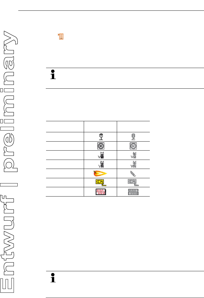
6 Using the product
65
1. Connect the readout adapter to the instrument (PS2 interface)
and to the automatic furnace (use adapter ring if necessary).
2. [] → Measurements → [OK] → Automatic Furnace →
[OK].
- The data are read from the automatic furnace. Depending on
the automatic furnace, the data are updated at the latest every
30 s.
The values are saved in a measuring report or transferred
to a pocket PC / PC, together with the measuring values of
a flue gas measurement.
Reading out current status data:
The current data are displayed after a connection has been set up
to the automatic furnace. The following data are displayed with the
help of symbols:
Component Status ON Status OFF
Air controller
Motor
Valve 1
Valve 2
Flame
Ignition
Oil prewarmer
Options
> [Options] → Clipboard: Data are saved to the clipboard.
> [Options] → Delete clipboard: Any data saved to the clipboard
is deleted.
> [Options] → Save: The readings are saved in a record.
> [Options] → Adapter Information: Type and version of
readout adapter are displayed.
> [Options] → Identification: Information about manufacturer
and type of automatic furnace
> [Options] → Statistics: Display of error statistics.
Automatic furnaces are equipped with a circular buffer
memory: Error messages are overwritten when the error log
is full. The fault that has occurred last is at position 1 in the
error list.
6 Using the product
66
> [Options] → Fault: Display of faults.
Pos: 80 /TD/Produkt verwenden/testo 330/tes to 330 Festbrennstof f @ 8\mod_1297327823279_ 79.docx @ 76933 @ 355 @ 1
6.2.16. Solid fuel measurement
The solid fuel measurement program is only available with
instruments that come with the CO sensor (not COlow). For
measurements in accordance with the 1st Federal Immission
Control Ordinance (BImSchV), a CO,H2-compensated sensor
(0393 0101) is required.
The function is only available if the activated fuel is solid
fuel and adapter 0600 9765 has been connected.
Calling up the function:
> [] → Measurement options → [OK] → Solid fuel → [OK].
Performing the measurement:
1. Select parameters gas phase, meas. rate or stability time: [▲],
[▼] → [Change].
2. Enter values. [▲], [▼]and partly [◄], [►] → [OK].
3. [Finished].
4. Insert the flue gas probe into the exhaust pipe and position it in
the hot spot.
5. Start measurement: []
- The stabilisation phase (minimum 2 min) progresses. After this
the measuring phase starts automatically (minimum 5 min).
The stabilisation phase can be interrupted early.
> Press [Next].
- The measuring phase starts automatically.
- The measuring result is displayed after the measuring phase
has been completed.
Options:
> [Options] → Clipboard: Data are saved to the clipboard.
> [Options] → Delete clipboard: Data in the clipboard are
deleted.
> [Options] → Save: The readings are saved in a record.
> [Options] → Show Graphic: The readings are displayed in
form of a line graph.
> [Options] → Configure Graphic: The measurement
parameters to be represented (max. 4) can be displayed ( ) or
hidden ( ) werden.

6 Using the product
67
> [Option] → Measurement view: (This function is not available
during a measurement): The readings display menu is opened.
Pos: 81 /TD/Produkt verwenden/testo 330/tes to 330 Gasleitungspr üfungen @ 6\mod_12791993 18613_79.docx @ 66483 @ 34545 45455 @ 1
6.2.17. Gas pipe tests
Calling up the function:
> [] → Measurements → [OK] → Gas Pipe Tests → [OK].
6.2.17.1. Tightness test 1
Leak test on gas pipes acc. to DVGW-TRGI 2008
worksheet G600
The leak test (using air or inert gas, e.g. CO2 or N2) is used
for acceptance testing of newly routed or remedied pipes.
The test is performed at the pipe, including the fittings,
without gas installations and corresponding control and
safety equipment. For this test the line must be pressurised
with 150 mbar, whereby this pressure must remain constant
for 10 minutes.
This applies to lines < 100 l. For larger line volumes, the
stability time and measurement period should be adjusted
in accordance with DVGW-TRGI 2008 worksheet G600.
> Connect the connecting plug of the hose pressure connection
set (0554 1203) to the pressure test set (0554 1213), plug the
pressure adapter onto the flue gas socket and lock in place by
slightly turning it clockwise (bayonet lock).
Performing the measurement:
✓ The pressure socket of the instrument must be free (i.e.
unpressurized, not closed).
1. Tightness Test 1 → [OK].
- Pressure zeroing.
2. Select parameter: [▲], [▼] → [Edit].
3. Set parameters or enter values: [▲], [▼] and partly [◄], [►]→
[OK].
4. Pressurise the system.
Once the pressure has built up, a stability time specified by
DVGW-TRGI 2008 should be observed to ensure that any
possible pressure fluctuations are not recorded in the
measurement. The relevant standard provides more
detailed information.
5. Start measurement: [].
6 Using the product
68
- The stability time will run. After this the measuring phase starts
automatically.
> End stability time and measurement early: [Next].
- The readings are displayed when measurement has been
completed.
6.2.17.2. Tightness test 2
• Follow DVGW-TRGI 2008, worksheet G624.
• Pressure Absolute (parameter of location) must strictly
be entered to obtain correct readings. If this is unknown
it is recommended to use the value 966hPa
(corresponds with 1013 hPa barometric, altitude 400 m)
To enter the values:
> [] → Measurements → [OK] → Gas Pipe Tests →
[OK] → [Tightness Test 2] → [Fold./Meas.] →
[Options] → Edit Location.
> Plug the connecting plug of the hose connection set
(0554 1203) into the flue gas socket and lock in place by turning
it slightly clockwise (bayonet lock).
Performing the measurement:
✓ The pressure socket of the instrument must be free (i.e.
unpressurized, not closed).
1. Tightness Test 2 → [OK].
2. Select parameter: [▲], [▼] → [Edit].
3. Set parameters or enter values: [▲], [▼] and partly [◄], [►]→
[OK].
Three circular diameters and three pipe lengths can be
entered, which are then used to calculate three partial
volumes. The pipe volume is calculated by adding these
three partial volumes.
4. [measurement].
- Pressure zeroing.
5. Pressurise the system.
6. Start measurement: [].
- The stability time will run. After this the measuring phase starts
automatically.
> End stability time and measurement early: [Next].
- The readings and Result Tightness Test 2 are displayed when
measurement has been completed.
6 Using the product
69
7. [Edit] → Select test result: [▲], [▼] → [OK].
6.2.17.3. Let By Test
> Plug the connecting plug of the hose connection set
(0554 1203) into the flue gas socket and lock in place by turning
it slightly clockwise (bayonet lock).
Performing the measurement:
✓ The pressure socket of the instrument must be free (i.e.
unpressurized, not closed).
1. Let By Test → [OK].
- Pressure zeroing.
2. Select parameter: [▲], [▼] → [Edit].
3. Set parameters or enter values: [▲], [▼] and partly [◄], [►]→
[OK].
4. Pressurise the system.
5. Start measurement: [].
- The stability time will run. After this the measuring phase starts
automatically.
> End stability time and measurement early: [Next].
- The readings and Result Let By Test are displayed when
measurement has been completed.
6. [Edit] → Select test result: [▲], [▼] → [OK].
6.2.17.4. Leak detection
In gas leak detection no measurement is made, but a gas detection
is performed.
✓ A gas leak probe (0632 3330) must be connected.
You must also refer to the documentation that comes with
the gas leak probe.
Calling up the function:
> Leak Detection→ [OK].
Performing the detection:
> Set the gas type to be detected and perform gas leak testing by
following the instructions described in the documentation of the
gas leak probe.
1. Start detection: [].
- The gas concentration is displayed, if it exceeds the limit an
alarm signal will sound.
7 Maintaining the product
70
Options:
> [Options] → Save: the readings are saved in a record.
> [Options] → Show Graphic: The readings are displayed in
form of a line graph.
> [Options] → Alarm Limit: (This function is not available during
a measurement): Adjusting alarm limits.
> [Options] → Alarm Signal: (This function is not available
during a measurement): Alarm signal disable/enable.
> [Options] → Zeroing Probe: Perform zeroing.
> [Options] → Sensor detection: newly inserted sensor is
detected.
2. End detection: [].
Pos: 82 /TD/Produkt verwenden/testo 330/tes to 330 Überschrif t Daten übertragen @ 6\mod_12792 58550805_79.doc x @ 66583 @ 2 @ 1
6.3. Transferring data
Pos: 83 /TD/Produkt verwenden/testo 330/tes to 330 Daten übertragen @ 6\ mod_1279258680964_79. docx @ 66614 @ 33 @ 1
6.3.1. Report printer
To be able to transmit data via infrared or Bluetooth interface to a
Testo report printer, the printer to be used must have been
activated, see Printer, page 46.
Printing out data takes place via [Print] or []. The function is only
available if a printout is possible.
Representation of the available characters per line is
limited on the printout. Thus, the unit mg/KWh is displayed
on the printout as mg/k.
6.3.2. PC / Pocket PC
Data transfer to a PC can take place via USB, IrDA or Bluetooth®.
Data transfer to a Pocket PC can take place via IrDA or Bluetooth®.
You must also refer to the documentation that comes with the
software.
Pos: 84 /TD/Überschr iften/7. Produkt ins tand halten @ 0\mod_1173789 831362_79.doc x @ 397 @ 1 @ 1
7 Maintaining the product
Pos: 85 /TD/Produkt ins tand halten/testo 33 0/testo 330 Instandhal tung_Messgerät rei nigen @ 6\mod_1279260289 656_79.docx @ 66679 @ 2 @ 1
7.1. Cleaning the measuring instrument
> If the housing of the measuring instrument is dirty, clean it with
a damp cloth. Do not use any aggressive cleaning agents or
solvents! Mild household cleaning agents and soap suds may
be used.
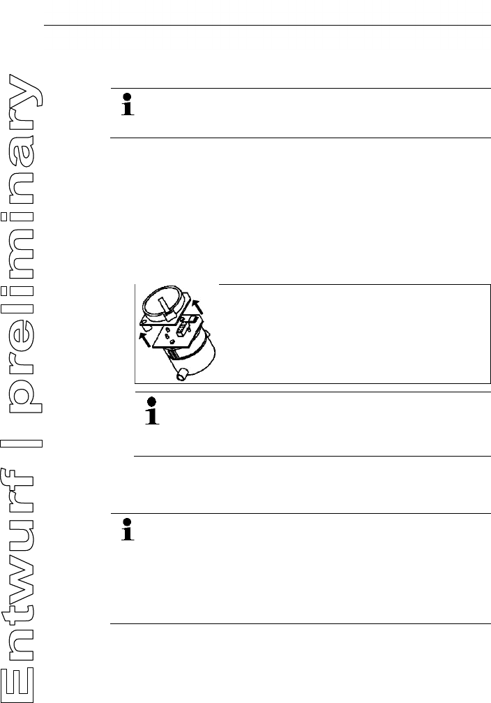
7 Maintaining the product
71
Pos: 86 /TD/Produkt ins tand halten/testo 330/ testo 330 Instandhal tung_Sensoren wechs eln @ 6\mod_12792605910 98_79.docx @ 66711 @ 22 @ 1
7.2. Replacing sensors
A slot bridge (0192 1552) must be inserted in slots which
are not equipped with a sensor. Used sensors must be
disposed of as hazardous waste!
✓ The instrument must be switched off.
1. Place the measuring instrument on its front.
2. Remove the service cover: Take hold of it at the markings
(arrows) using the index finger and thumb, press slightly, fold
up and remove.
3. Pull hose connections from the faulty sensor / bridge.
4. Remove the faulty sensor / bridge from the slot.
> For NO-sensor: Remove the auxiliary circuit board.
Do not remove the auxiliary circuit board for the NO-
sensor until immediately before installation. Do not
leave the sensor without auxiliary circuit board for
longer than 15 min.
5. Install new sensor / new bridge in the slot.
6. Plug the hose connections on sensor / bridge.
7. Attach the service cover and engage it in place.
After replacing an O2 sensor, wait for an equalisation
period of 60 min to elapse before using the instrument
again.
When retrofitting a sensor the associated measurement
parameter and unit must be enabled, see Fehler!
Verweisquelle konnte nicht gefunden werden., page
Fehler! Textmarke nicht definiert..
7.3. Recalibrating / adjusting sensors
See Sensor settings, page 48.
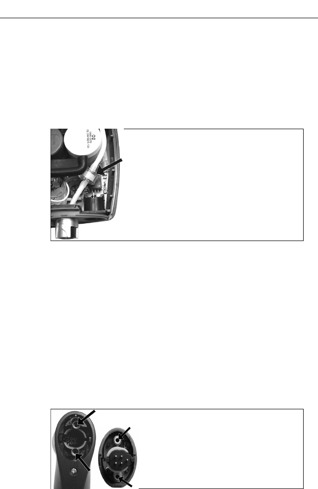
7 Maintaining the product
72
Pos: 87 /TD/Produkt ins tand halten/testo 33 0/testo 330 Instandhal tung_Zusatzfilter wechseln @ 6\mod_1279261 725966_79.doc x @ 66743 @ 2 @ 1
7.4. Replacing additional filter
The additional filter provides added protection should problems
occur with the particle filter in the flue gas probe. The additional
filter is very rarely contaminated if the measuring instrument is used
normally.
> Check the additional filter (visually) periodically for
contamination and replace it if necessary.
1. Place the measuring instrument on its front.
2. Remove the service cover: Take hold of it at the markings
(arrows) using the index finger and thumb, press slightly, fold
up and remove.
3. Loosen the additional filter from the hose connection.
4 Plug the new filter (0133 0010) into the hose connection.
5. Attach the service cover and engage it in place.
Pos: 88 /TD/Produkt ins tand halten/testo 330 und t esto 350 neu/testo 330/ 350 Instandhaltung Ab gassonde reinigen @ 6\ mod_1270039302035_79. docx @ 60667 @ 2 @ 1
7.5. Cleaning the modular flue gas probe
✓ Disconnect the flue gas probe from the measuring instrument
prior to cleaning.
1. Release the probe catch by pressing the key on the probe
handle and remove the probe module.
2. Blow compressed air through the flue gas ducts in probe
module and probe handle (see illustration). Do not use a brush!
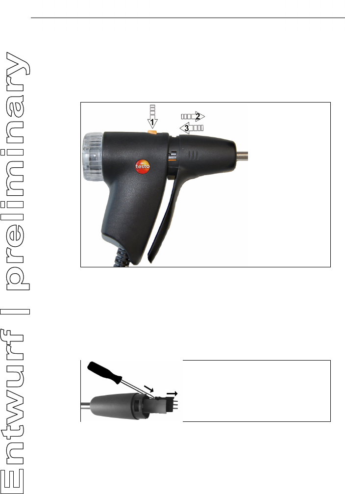
7 Maintaining the product
73
3. Fit a new probe module on the probe handle and engage it in
place.
Pos: 89 /TD/Produkt ins tand halten/testo 330/ testo 330 Sondenmodul wechseln @ 6\mod_12792631 31873_79.docx @ 66807 @ 2 @ 1
7.6. Replacing the probe module
✓ Disconnect the flue gas probe from the measuring instrument.
1. Press the button on the top of the probe handle (1) and remove
the probe module (2).
2. Plug in the new probe module and lock it in place (3).
Pos: 90 /TD/Produkt ins tand halten/testo 330 und t esto 350 neu/testo 330/ 350 Instandhaltung Thermoelement wechseln @ 6\m od_1270039469873_ 79.docx @ 60729 @ 2 @ 1
7.7. Changing the thermocouple
1. Release the probe catch by pressing the key on the probe
handle and remove the probe module.
2. Remove the thermocouple plug-in head from the socket using a
screwdriver and pull the thermocouple out of the probe shaft.
3. Keep inserting the new thermocouple into the probe shaft until
the connection head clicks into place.
4. Fit a new probe module on the handle and engage in place.
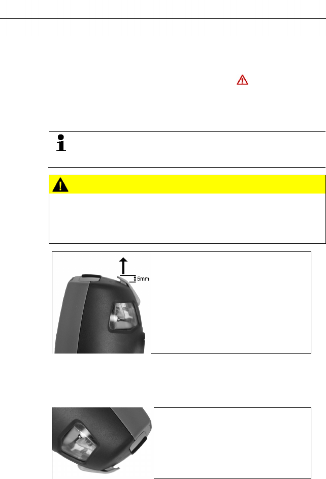
7 Maintaining the product
74
Pos: 91 /TD/Produkt ins tand halten/testo 330/ testo 330_Instandha ltung Kondensatbehä lter @ 6\mod_1279263636 301_79.docx @ 66871 @ 25 @ 1
7.8. Condensate container
The fill level of the condensate trap can be read from the markings
on the condensate trap. A warning message ( , red flashing light)
is displayed if the fill level in the condensate trap reaches 90 %.
The fill level of the condensate trap can be read from the markings.
Draining the condensate trap
The condensate consists of a weak mix of acids. Avoid skin
contact. Make sure that the condensate does not run over
the housing.
CAUTION
Condensate entering the gas path.
Damage to sensors and flue gas pump!
> Do not empty the condensate trap while the flue gas pump is in
operation.
1. Unlock the condensate trap and pull it vertically off the
measuring box.
2. Open the condensate outlet on the condensate trap: Pull out
approx. 5 mm against the stop.
3. Let the condensate run out into a sink.
4. Wipe off any drops still on the condensate outlet with a cloth
and close the condensate outlet.
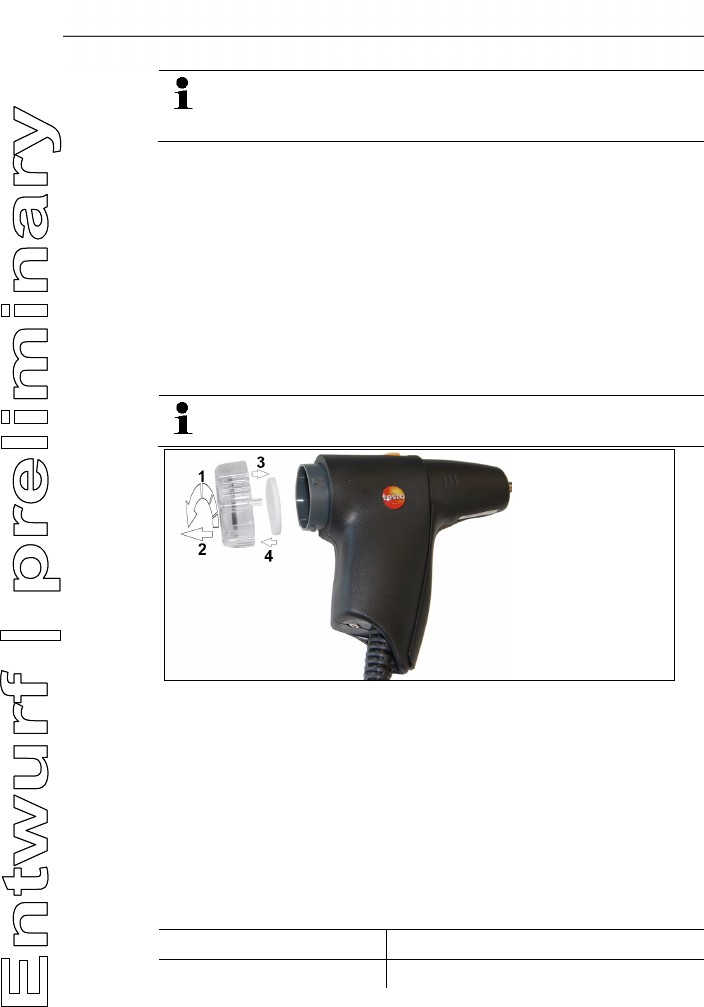
8 Tips and assistance
75
The condensate outlet must be completely closed
(marking), otherwise measuring errors could be caused by
infiltrated air.
Pos: 92 /TD/Produkt ins tand halten/testo 330/ testo 330 Instandhal tung Partikelfil ter prüfen @ 6\mod_12792655 18333_79.docx @ 66943 @ 255 @ 1
7.9. Checking/replacing the particle filter
Checking the particle filter:
Check the particle filter of the modular flue gas probe periodically
for contamination: check visually by looking through the window
of the filter chamber.
> If there is visible contamination or inadequate pump flow,
replace the filter.
Replacing the particle filter:
The filter chamber may contain condensate. This is not a
malfunction and will not cause wrong readings.
1. Open the filter chamber: turn slightly anti-clockwise (1). Remove
the filter chamber (2).
2. Remove the filter plate (3) and replace it with a new one (4
[0554 3385]).
3. Attach the filter chamber and lock it: turn slightly clockwise.
Pos: 93 /TD/Überschr iften/8. Tipps und Hilfe @ 0\mod_1173789887985 _79.docx @ 406 @ 1 @ 1
8 Tips and assistance
Pos: 94 /TD/Überschr iften/8.1 Fragen und Ant worten @ 0\mod_117740201 7078_79.docx @ 1093 @ 2 @ 1
8.1. Questions and answers
Pos: 95 /TD/Tipps und Hilf e/Fragen und Antworten/ testo 330 Fragen und Anwor ten @ 6\mod_127926654784 4_79.docx @ 66975 @ @ 1
Question Possible causes / solution
Rechargeable battery low > Switch to mains operation.

8 Tips and assistance
76
Question Possible causes / solution
Measuring instrument
switches automatically off
or cannot be switch on
Batteries / rechargeable batteries
empty.
> Charge rechargeable batteries or
switch to mains operation.
Displayed battery capacity
seems to be faulty
Rechargeable battery was repeatedly
not fully discharged/charged.
> Discharge rechargeable battery
(until measuring instrument
switches off automatically) and
then charge fully.
Error message: Pump
flow too high
Gas outlet blocked
> Make sure that the gas outlet is
clear.
Error message: Sensor
protection active
The shutdown limit of the CO sensor
was exceeded.
> Remove the probe from the stack.
Error message:
Printing not
possible
• With printer 0554 0543: Bluetooth
interface not activated.
• Wrong printer activated.
• Printer switched off.
• Printer outside wireless
transmission range.
> Activate Bluetooth interface, see
Bluetooth®, page 46.
> Activate printer used, see Printer,
page 46.
• Switch on printer.
> Move printer within wireless
transmission range.
If we could not answer your question, please contact your dealer or
Testo Customer Service. Contact data see back of this documet or
website www.testo.com/service-contact.
Pos: 96 /TD/Überschr iften/8.3 Zubehör und Er satzteile @ 0\mod_117740 2058734_79.doc x @ 1102 @ 2 @ 1
8.2. Accessories and spare parts
Pos: 97 /TD/Tipps und Hi lfe/Zubehör und Ersatzt eile/testo 330 Zuberhör _Ersatzteile @ 6\ mod_1279267635925_79. docx @ 67007 @ 555555555 @ 1
Printer
Description Article no.
Infrared high-speed printer 0554 0549
8 Tips and assistance
77
Description Article no.
Bluetooth® /IRDA printer, incl. Mains unit 5 V / 1.0 A
with micro USB cable
0554 0620
Mains unit 5 V / 1.0 A with micro USB cable 0554 1105
Spare thermal paper for printer (6 rolls) 0554 0568
Modular flue gas probes
Description Article no.
Modular flue gas probe 180 mm, 500 °C,
thermocouple 0.5 mm, probe shaft diameter: 8mm
0600 9760
Modular flue gas probe 300 mm, 500 °C,
thermocouple 0.5 mm, probe shaft diameter: 8mm
0600 9761
Modular flue gas probe 180 mm, 500 °C,
thermocouple 0.5 mm, probe shaft diameter: 6mm
0600 9762
Modular flue gas probe 300 mm, 500 °C,
thermocouple 0.5 mm, probe shaft diameter: 6mm
0600 9763
Flexible flue gas probe, length 330 mm,
Tmax. 180 °C, short-term 200 °C, bending radius
max. 90° for measurements at difficult to access
locations
0600 9770
Probe modules / accessories for modular flue gas probes
Description Article no.
Probe shaft module 180 mm, 500 °C, thermocouple
0.5 mm, probe shaft diameter: 8 mm
0554 9760
Probe shaft module 300 mm, 500 °C, thermocouple
0.5 mm, probe shaft diameter: 8 mm
0554 9761
Probe shaft module 180 mm, 500 °C, thermocouple
0.5 mm, probe shaft diameter: 6 mm
0554 9762
Probe shaft module 300 mm, 500 °C, thermocouple
0.5 mm, probe shaft diameter: 6 mm
0554 9763
Probe shaft module 300 mm, 1,000 °C,
thermocouple 1.0 mm, probe shaft diameter: 6 mm
0554 8764
Probe shaft module 700 mm, 1,000 °C,
thermocouple 1.0 mm, probe shaft diameter: 6 mm
0554 8765
Spare thermocouple for module 0554 9760,
0554 9762
0430 9760

8 Tips and assistance
78
Description Article no.
Spare thermocouple for module 0554 9761,
0554 9763
0430 9761
Spare thermocouple for module 0554 8764 0430 8764
Spare thermocouple for module 0554 8765 0430 8765
Cone, 8 mm, steel 0554 3330
Cone, 6 mm, steel 0554 3329
Multi-hole probe shaft, length 300 mm, Ø 8 mm, for
CO averaging
0554 5762
Multi-hole probe shaft, length 180 mm, Ø 8 mm, for
CO averaging
0554 5763
Flexible probe shaft module 0554 9770
Hose extension 2.8 m, extension line probe -
instrument
0554 1202
Particle filter, 10 pcs. 0554 3385
Temperature sensor
Description Article no.
Ambient air temperature (AT) probe, 300 mm 0600 9791
Ambient air temperature (AT) probe, 190 mm 0600 9787
Ambient air temperature (AT) probe, 60 mm 0600 9797
Fast reaction surface sensor 0604 0194
Miniature ambient air sensor 0600 3692
Other probes / sensors
Description Article no.
O2 annular gap probe 0632 1260
Gas leak probe 0632 3330
Ambient CO probe 0632 3331
CO2 ambient probe (without connecting cable) 0632 1240
Connecting cable for CO2 ambient probe, 1.5 m 0430 0143
Gas pressure set: Draught path adapter, silicone
hose 4 mm / 6 mm, reducing cones
0554 1203
8 Tips and assistance
79
Description Article no.
Differential temperature set, 2 pipe wrap probes,
adapter
0554 1204
Smoke tester inc. oil, soot plates, for measuring soot
in flue gas
0554 0307
Retrofit sensors
Description Article no.
NO retrofit 0554 2151
Spare sensors
Description Article no.
O2 sensor 0393 0002
O2 sensor 0393 0051
O2 sensor H2 compensated 0393 0101
COlow sensor 0393 0103
NO sensor 0393 0151
NOlow sensor 0393 0152
Cases
Description Article no.
System case with double floor (height:180 mm) for
instrument, probes and accessories
0516 3301
System case (height: 130 mm) for instrument,
probes and accessories
0516 3300
System case with tool pouch without contents 0516 0329
Other accessories
Description Article no.
Mains unit 0554 1096
Charger with spare rechargeable battery 0554 1103
Spare rechargeable battery 0515 0107
Readout adapter for automatic furnaces 0554 1206
Connecting cable instrument / PC 0449 0047

8 Tips and assistance
80
Description Article no.
Aasyheat (PC configuration software) 0554 3332
Additional filter 0133 0010
Draught set 0554 3150
Fine pressure probe 0638 0330
Set of capillary hoses 0554 1215
Solid fuel measurement module with adapter and
probe shaft with sintered filter
0600 9765
Sintered filter for solid fuel measurement probe shaft 0133 0035
Filter material for condensate trap on solid fuel
measurement adapter
0133 0012
NOx-Filter 0554 4150
Pressure test set for gas line testing 0554 1213
Straight Pitot tube 0635 2050
ISO Calibration Certificate Flue Gas 0520 0003
For a complete list of all accessories and spare parts, please refer
to the product catalogues and brochures or look up our website
www.testo.com
Pos: 98 /TD/Tipps und Hi lfe/testo 330 Instand haltung Update Firmwar e @ 6\mod_1279805277750_79. docx @ 67273 @ 2 @ 1
8.3. Updating the instrument software
Under www.testo.com/download-center you can download the
current instrument software (Firmware) for testo 330 (registration
required).
> Unplug the mains unit and switch off the testo 330.
1. Hold [▲] depressed.
2. Plug in the mains unit, keep [▲] depressed.
- The display shows Firmware update along the bottom edge.
3. Release [▲] .
4. Insert the connecting cable (0449 0047) into the USB-port on
the instrument, then connect it to the PC.
- Your PC recognises the testo 330 as a removable medium.
5. Copy the new file (ap330rel.bin) to the detected removable
medium.
- In the display the status bar progresses from left to right. This
process may take a few minutes.
6. Disconnect the connecting cable from the testo 330.

8 Tips and assistance
81
- After updating of the instrument software (Firmware) has been
completed the system will automatically reboot and is ready for
use.
=== Ende der Liste für Textmarke Inhalt ===

0970 3310 en 10a V02.11 en_DE

8 Tips and assistance
83