Testo SE and KGaA 2016T330I testo 330i - flue gas analyzer User Manual
Testo AG testo 330i - flue gas analyzer Users Manual
Users Manual
testo 330i · Flue gas measuring instrument
Instruction manual

2

1 Contents
3
Pos: 1 /TD/Überschr iften/1. Inhalt @ 0\mod_1 177587817070_79.doc x @ 1243 @ 1 @ 1
1 Contents
1 Contents ................................................................................................... 3
2 Safety and the environment .................................................................... 6
3 Use ............................................................................................................ 6
4 Product description ................................................................................. 7
4.1. Measuring instrument ...................................................................... 7
4.1.1. Overview .......................................................................................................... 7
4.1.2. Terminal panel left/right ................................................................................... 9
4.2. Modular flue gas probe .................................................................... 9
5 First steps .............................................................................................. 10
5.1. Commissioning .............................................................................. 10
5.2. Getting to know the product ........................................................... 10
5.2.1. Connecting probes ......................................................................................... 10
5.2.2. Mains unit/rechargeable battery ..................................................................... 10
5.2.2.1. Charging the rechargeable battery .................................................. 10
5.2.2.2. Mains operation ............................................................................... 11
5.2.3. Switching on and connecting with a mobile terminal device ........................... 11
5.2.4. Switching off .................................................................................................. 12
5.2.5. Using the App ................................................................................................ 12
6 Using the product .................................................................................. 13
6.1. Performing settings ........................................................................ 13
6.1.1. Configuring measurements..................................................................... 13
6.1.2. Graphics ........................................................................................................ 14
6.1.3. | Instrument settings | Language ............................................................ 14
6.1.4. | Instrument settings | Country version ................................................... 14
6.1.5. (Fuels) .................................................................................................... 15
6.1.6. | Instrument settings | Sensor protection ................................................ 15
6.1.7. | Instrument settings | Sensor protection ................................................ 15
6.1.8. | Instrument settings | O2 reference ........................................................ 15
6.1.9. | Instrument settings | O2 addition .......................................................... 15
6.1.10. | Instrument settings | Height compensation .......................................... 15
6.1.11. | Instrument settings | Sensor protection ................................................ 16
6.1.12. | Instrument settings | Sensor protection ................................................ 16
6.2. Measuring ...................................................................................... 16
6.2.1. Preparing for measurement ........................................................................... 16
6.2.1.1. Checking the condensate container fill level .................................... 16
6.2.1.2. Checking the particle filter ............................................................... 16
6.2.1.3. Zeroing phases ................................................................................ 16
1 Contents
4
6.2.1.4. Performing a gas path check ........................................................... 17
6.2.1.5. Installing the probe mount testofix® ................................................ 17
6.2.1.6. Using the modular flue gas probe .................................................... 19
6.2.2. | Flue gas ................................................................................................ 20
6.2.3. | Draught ................................................................................................. 21
6.2.4. | BImSchV ............................................................................................... 21
6.2.5. | COundiluted .......................................................................................... 21
6.2.6. | Smoke number ...................................................................................... 22
6.2.7. | Differential pressure .............................................................................. 22
6.2.8. | Differential temp. ................................................................................... 22
6.2.9. | O2 supply air .......................................................................................... 23
6.2.10. | Differential temp. ................................................................................... 23
6.2.11. | Differential temp. ................................................................................... 23
6.3. Printing readings ........................................................................... 23
6.4. Report ........................................................................................... 24
6.4.1. Add to protocol (save measurement) ............................................................. 24
6.4.2. Finish protocol ............................................................................................... 24
7 Maintaining the product ....................................................................... 26
7.1. Checking instrument status ........................................................... 26
7.1.1. | Instrument settings | Sensor diagnosis ................................................ 26
7.1.2. | Error list ............................................................................................... 26
7.2. Cleaning the measuring instrument .............................................. 26
7.3. Draining the condensate container ............................................... 26
7.4. Opening the measuring instrument ............................................... 27
7.5. Replacing the rechargeable battery .............................................. 30
7.6. Replacing sensors ........................................................................ 31
7.7. Cleaning the modular flue gas probe ............................................ 32
7.8. Replacing the probe module ......................................................... 32
7.9. Checking/replacing the particle filter ............................................. 33
7.10. Changing the thermocouple .......................................................... 34
7.11. Updating the instrument software ................................................. 34
8 Technical data ....................................................................................... 35
8.1.1. Examinations and licenses ............................................................................ 35
8.1.2. Bluetooth® module ......................................................................................... 35
8.1.3. Measuring ranges and resolution ................................................................... 38
8.1.4. Accuracy and response time .......................................................................... 38
8.1.5. Other instrument data .................................................................................... 40
8.1.6. Declaration of conformity ............................................................................... 42
9 Tips and assistance .............................................................................. 43

1 Contents
5
9.1. Questions and answers ................................................................. 43
9.2. Accessories and spare parts ......................................................... 44
Pos: 2 /TD/--- Seitenwechsel --- @ 0\mod_1173774430601_0. docx @ 283 @ @ 1

3 Use
6
Pos: 3 /TD/Überschr iften/2. Sicher heit und Umwelt @ 0\mod_117377471935 1_79.docx @ 292 @ 1 @ 1
2 Safety and the environment
Pos: 4 /TD/Sicherhei t und Umwelt/Verweis auf " Inbetriebnahme und Si cherheit" - Kap. Sic herheit @ 18\mod_143799616456 3_79.docx @ 216177 @ @ 1
Please note the information in the document Commissioning and
Safety (printed version supplied with the product). Make sure that
all product users read and observe the safety information!
Pos: 5 /TD/Überschr iften/3. Verwendung @ 18\m od_1437996869580_7 9.docx @ 216211 @ 1 @ 1
3 Use
Pos: 6 /TD/Leistungsbe schreibung/Verwendu ng/testo 3xx/tes to 330i_Verwendung @ 17\m od_1432802471780_79.d ocx @ 213305 @ @ 1
The testo 330i is a flue gas measuring instrument which in
combination with a separate Android or iOS mobile device and the
testo 330i App enables professional flue gas analysis of
combustion systems:
• Small combustion systems (oil, gas, wood, coal)
• Low-temperature and condensing boilers
• Gas water heaters
These systems can be adjusted using the instrument and checked
for compliance with the applicable limit values.
The instrument has been verified as a short-term measuring
instrument and should not be used as a safety (alarm) instrument.
The following tasks can also be carried out using the instrument:
• Regulating the O2, CO and CO2, NO, NOx values in furnaces for
the purpose of ensuring optimal operation.
• Draught measurement.
• Measuring and regulating the gas flow pressure in gas water
heaters.
• Measuring and optimising the flow and return temperatures of
heating systems.
• Ambient measurement - CO and CO2.
• Detection of CH4 (methane) and C3H8 (propane).
• The instrument can be used for measurements on combined
heat and power stations (CHP) in accordance with the
first German Federal Immission Control Ordinance (BImSchV).
• In principal, the CO sensor can also be used for
measurements on CHP stations. If you should carry out
more than 50 measurements on CHP stations per year,
please contact your nearest Testo service centre or send
the testo 330i to testo Service for inspection.
A worn NOx filter of the CO sensor can be ordered as a
spare part (item no. 0554 4150) and replaced.
4 Product description
7
Testo guarantees the functionality of its products when
used in accordance with their intended purpose. This
guarantee does not apply to features of Testo products in
combination with unauthorised third-party products.
Competitor products are not authorised by Testo.
As is common practice, Testo generally excludes support,
warranty or guarantee claims relating to functionality that
has not been guaranteed by Testo as part of the product
offered. Claims shall also be excluded in the event of
improper use or handling of the products, e.g. in
combination with unauthorised third-party products.
Pos: 7 /TD/00-WI CHTIG, prüfen, ggf. einf ügenFunk-Modul Verwendung ( BT) @ 17\mod_143504385431 4_79.docx @ 214068 @ @ 1
The use of the wireless module is subject to the regulations and
stipulations of the respective country of use, and the module may only
be used in countries for which a country certification has been granted.
The user and every owner has the obligation to adhere to these
regulations and prerequisites for use, and acknowledges that the re-
sale, export, import etc. in particular in countries without wireless
permits, is his responsibility.
Pos: 8 /TD/Überschr iften/4. Produktbesc hreibung @ 0\mod_11737 74846679_79.docx @ 310 @ 1 @ 1
4 Product description
Pos: 9 /TD/Produktbe schreibung/Übersic ht/testo 3xx/tes to 330/testo 330i Übersi cht @ 17\mod_14328878520 94_79.docx @ 213517 @ 2333 @ 1
4.1. Measuring instrument
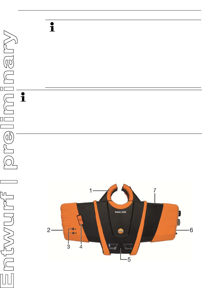
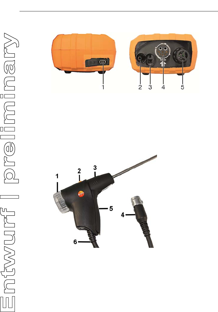
4.1.1. Overview
1 Retaining bracket: for attaching to the probe mount testofix®
2 Terminal panel left
4 Product description
8
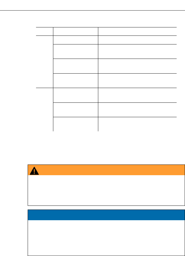
3 Status LEDs:
LED Display Meaning
Blue Off Instrument off or not ready
Flashes (0.05 s
on/0.5 s off) Instrument on, start up phase
Flashes (0.5 s
on/0.5 s off) Instrument on, Bluetooth® Find
Device activated
Light is constant Instrument on, Bluetooth®
connection activated
Red Flashes (0.05 s
on/0.5 s off) Device error
Flashes (0.5 s
on/0.5 s off) Mains unit plugged in, battery
charging
Light is constant Mains unit plugged in, battery
fully charged
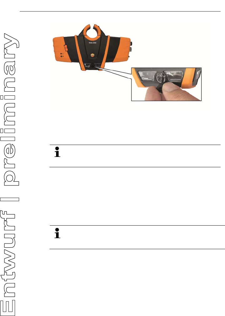
4 ON/OFF button
5 Condensate container, condensate outlet plug
6 Terminal panel right
7. Magnetic holder (on rear)
WARNING
Magnetic field
May be harmful to those with pacemakers.
> Keep a minimum distance of 15 cm between pacemaker and
instrument.
ATTENTION
Magnetic field
Damage to other devices!
> Keep a safe distance away from products that could be
damaged by the effects of magnetism (e.g. monitors,
computers or credit cards).
4 Product description
9
4.1.2. Terminal panel left/right
1 USB interface
2 Minus connection for differential pressure measurement
3 Mains unit socket
4 Flue gas socket
5 Probe socket
4.2. Modular flue gas probe
1 Removable filter chamber with window and particle filter
2 Probe module lock release
3 Probe module
4 Connector plug for measuring instrument
5 Probe handle
6 Connecting cable
5 First steps
10
Pos: 10 /TD/Überschr iften/5. Erste Schr itte @ 0\mod_1173774895039_ 79.docx @ 319 @ 2 @ 1
5 First steps
Pos: 11 /TD/Überschr iften/5.1 Inbetriebn ahme @ 0\mod_1185342823 812_79.docx @ 1885 @ 2 @ 1
5.1. Commissioning
Pos: 12 /TD/Erste Sc hritte/Verweis auf "I nbetriebnahme und Sicher heit" - Kap. Inbetriebnah me @ 18\mod_14379975672 95_79.docx @ 216281 @ @ 1
Please note the information in the document Commissioning and
Safety (printed version supplied with the product).
Pos: 13 /TD/Überschr iften/5.3 Produkt kenn enlernen @ 0\mod_11853 42901015_79.docx @ 1894 @ 2 @ 1
5.2. Getting to know the product
Pos: 14 /TD/Erste Sc hritte/testo 330/test o 330i Produkt kennenler nen Sonden/Fühler ansc hließen @ 18\mod_14374 01463337_79.docx @ 215912 @ 355 @ 1
5.2.1. Connecting probes
Always connect the probes to the flue gas socket or probe
socket before switching on the measuring instrument;
switch the measuring instrument off and restart after
replacing a probe.
Connecting flue gas probes/gas pressure
adapters/temperature adapters
> Insert the connector plug into the flue gas socket and lock by
slightly turning it clockwise (bayonet lock).
There must be no more than one extension lead (0554
1201) between measuring instrument and flue gas probe.
Connecting other probes
> Insert the connector plug of the probe into the probe socket.
Pos: 15 /TD/Erste Sc hritte/testo 330/test o 330i Produkt kennenler nen Netzteil_Akkus _Batt @ 18\mod_143740096725 3_79.docx @ 21587 7 @ 3445 @ 1
5.2.2. Mains unit/rechargeable battery
If the mains unit is connected, the measuring instrument is
automatically powered from the unit.
5.2.2.1. Charging the rechargeable battery
The rechargeable battery can only be charged at an ambient
temperature of 0 to 35 °C. If the rechargeable battery pack has
discharged completely, the charging time at room temperature is
approx. 5-6 hrs.
1. Connect the instrument plug of the mains unit to the mains unit
socket on the measuring instrument.
2. Plug the mains plug of the mains unit into a mains socket.
- The charging process starts (red LED flashes: 0.5 s on/0.5 s
off).

5 First steps
11
- The charging process stops automatically when the battery is
charged (red LED is constant).
Rechargeable battery care
• Do not fully exhaust rechargeable batteries.
• Store rechargeable batteries only if charged and at low
temperatures, but not below 0 °C. The best storage conditions
are with a charge level of 30-70% and an ambient temperature
of 0-15 °C. Fully charge before using again.
• Optimal charging temperature at 20 °C ambient temperature.
• Trickle charging should not exceed 2 days.
5.2.2.2. Mains operation
1. Connect the instrument plug of the mains unit to the mains unit
socket on the measuring instrument.
2. Plug the mains plug of the mains unit into a mains socket.
- The measuring instrument is powered via the mains unit.
- If the measuring instrument is switched off and a rechargeable
battery is inserted, the charging process will start automatically.
Switching the measuring instrument on has the effect of
stopping the battery charging and the measuring instrument is
then powered via the mains unit.
Pos: 16 /TD/Erste Sc hritte/testo 330/test o 330i Produkt kennenler nen Ein/Aus, Verbi nden @ 17\mod_1435045795085 _79.docx @ 214062 @ 33 @ 1
5.2.3. Switching on and connecting with a mobile terminal
device
✓ The testo 330i App must be installed on your mobile terminal
device. Please note the information in the document
Commissioning and Safety (printed version supplied with the
product).
1. Switch on the measuring instrument: Press the key.
- Measuring instrument starts up: The blue LED flashes (0.05 s
on/0.5 s off).
- Connecting mode is activated: The blue LED flashes (0.5 s
on/0.5 s off).
2. Switch on the mobile terminal device.
3. Start up the testo 330i App on your mobile terminal device.
- The Find Device function is activated: Compatible devices
within wireless range are displayed (product designation +
serial number).
> Tap instrument designation to select an instrument.
- A Bluetooth® connection is established: The blue LED is
constant.

5 First steps
12
- Measurement type Flue Gas screen is displayed.
5.2.4. Switching off
Measuring values that have not been saved are lost when
the measuring instrument is switched off.
> Switch off the measuring instrument: Press the key.
- This may happen: the pump starts and the sensors are rinsed
until the switch-off thresholds (O2 > 20%, other measurement
parameters < 50 ppm) are reached. The maximum rinsing
period is 3 minutes.
- The measuring instrument switches off.
Pos: 17 /TD/Erste Sc hritte/testo 330/330i Pr odukt kennenlernen App- Bedienung @ 18\mod_1438 342301782_79.doc x @ 216656 @ 33 @ 1
5.2.5. Using the App
Make sure you are familiar with how your mobile terminal device
works before using the App; observe the documentation for your
mobile terminal device.
Actions are mainly carried out by touching an icon, a symbol, or a
name.
Some actions require a different gesture. This is pointed out in
each case in this documentation.
User interface
FEHLER - Variable ohne Inhalt
1 : Open the Measurement Types selection list
2 : Open/close the Menu selection list
3 : Open the Fuels selection list
4 Select reading display type
5 : Open the Options selection list
6 Start/stop measurement
7 : Open the Protocols selection list
Please also take note of the tutorial in the App under | Help |
Tutorial.
6 Using the product
13
Pos: 18 /TD/Überschr iften/6. Produkt ver wenden @ 0\mod_117377492855 4_79.docx @ 328 @ 2 @ 1
6 Using the product
Pos: 19 /TD/Überschr iften/6.1 Einstellun gen vornehmen @ 0\mod_11845 84321421_79.doc x @ 1863 @ 3 @ 1
6.1. Performing settings
Pos: 20 /TD/Produkt ver wenden/testo 330ites to 330i Messwertanzeig e @ 18\mod_1438350052777 _79.docx @ 216910 @ 45 @ 1
6.1.1. Configuring measurements
The measurement parameters/units and the number and order of
displayed measurement parameters in the reading display type can
be set in the List.
Only those parameters and units that are enabled in the reading
display appear in the measured value display, in the saved
measurement records and on the record printouts.
The settings only apply to the measurement type currently
activated.
Overview of measurement parameters (available selection depends
on the chosen measurement type, set fuel, and the sensors
available in the measuring instrument):
Display Measurement parameter
FT Flue gas temperature
AT Combustion air temperature
Itemp Instrument temperature
Pump Pumping capacity
O2 Oxygen
CO2 Carbon dioxide
qAnet Flue gas loss without due consideration of the
calorific value range
Effn Efficiency without consideration of the heat value
range
qAgr. Flue gas loss with due consideration of the
calorific value range
Effg Efficiency with due consideration of the calorific
value range
Draught Flue draught
∆P Differential pressure
CO Carbon monoxide
uCO Carbon monoxide undiluted
NO Nitrogen monoxide

6 Using the product
14
Display Measurement parameter
NOx Nitrogen oxide
λ Fuel-air ratio
AmbCO Ambient carbon monoxide
O2ref Oxygen reference
Dew Pt Flue gas dewpoint temperature
Performing actions
> To add a measurement parameter to the display list: Touch
Add to open the selection list of measurement parameters.
> To delete a measurement parameter from the display list:
Touch .
> Change the unit of a measurement parameter: Touch the
measurement parameter name to open the selection list of
measurement units.
> To change the position of a measurement parameter in the
display list: press down and drag.
> To accept changes: Touch Confirm.
Pos: 21 /TD/Produkt verwenden/testo 330i/t esto 330i Messwert-Dar stellungsart Grafi k @ 18\mod_1438355555554_ 79.docx @ 217018 @ 3 @ 1
6.1.2. Graphics
In the graphics reading display type, the reading progress can be
displayed as a line diagram.
A maximum of 4 measurement parameters can be set at any one
time. Only those measurement parameters/units can be displayed
that are available in the reading display type List.
> Touch to open the selection list of measurement
parameters/units.
Pos: 22 /TD/Produkt ver wenden/testo 330i/t esto 330i Sprache @ 17\mod_14 35060640365_79.doc x @ 214172 @ 3 @ 1
6.1.3. | Instrument settings | Language
The user interface language can be set.
The number of available languages depends on the activated
country version.
Pos: 23 /TD/Produkt ver wenden/testo 330ites to 330i Landesversion @ 17\ mod_1435061137749_7 9.docx @ 214242 @ 3 @ 1
6.1.4. | Instrument settings | Country version
The Country version configuration affects the measurement
parameters, fuels, fuel parameters, and the basis of and formulas
for calculations activated in the measurement box.
The country version setting affects the user screen languages that
can be enabled.

6 Using the product
15
Pos: 24 /TD/Produkt ver wenden/testo 330ites to 330i Brennstoffe @ 17\mod_1434440641647_7 9.docx @ 213817 @ 3 @ 1
6.1.5. (Fuels)
In order to obtain the correct readings the used fuel is to be set
before taking the readings.
Pos: 25 /TD/Produkt ver wenden/testo 330i/t esto 330i Sensordiagn ose @ 19\mod_145378948565 6_79.docx @ 226797 @ 3 @ 4
6.1.6. | Instrument settings | Sensor protection
Threshold values can be set to protect the CO/NO sensors against
overload. The sensor protection is activated if the threshold is
exceeded:
• Fresh air dilution if exceeded
• Shutdown if exceeded again
To disable sensor protection the threshold values must be set to
0 ppm.
Pos: 26 /TD/Produkt ver wenden/testo 330i/t esto 330i Sensorschut z @ 18\mod_1439470077571_ 79.docx @ 218787 @ 3 @ 1
6.1.7. | Instrument settings | Sensor protection
Threshold values can be set to protect the CO/NO sensors against
overload. The sensor protection is activated if the threshold is
exceeded:
• Fresh air dilution if exceeded
• Shutdown if exceeded again
To disable sensor protection the threshold values must be set to
0 ppm.
Pos: 27 /TD/Produkt ver wenden/testo 330i/t esto 330i O2-Referenz @ 18\ mod_1439470144870_79. docx @ 218857 @ 3 @ 1
6.1.8. | Instrument settings | O2 reference
The O2 reference value of the current fuel can be set.
Pos: 28 /TD/Produkt ver wenden/testo 330i/t esto 330i NO2-Zuschlag @ 18\ mod_1439470169269_79. docx @ 218892 @ 3 @ 1
6.1.9. | Instrument settings | O2 addition
The NO2 addition value can be set.
Pos: 29 /TD/Produkt ver wenden/testo 330i/t esto 330i Höhenkompens ation @ 18\mod_1439470121 376_79.docx @ 218822 @ 3 @ 1
6.1.10. | Instrument settings | Height compensation
Extremely low absolute pressure causes wrong calculation of the
O2 sensor service life. Therefore, when the measuring instrument is
used at great heights, the factory set value should be adjusted so
that an O2 sensor is not displayed prematurely as “expended”.
If using the measuring instrument at heights up to approx. 1800 m
above mean sea level (MSL), the factory setting (922 hPa, equals
approx. 800 m above MSL) can be retained.
The value can be input directly (Abs. pressure), or is automatically
calculated when entering the barometric pressure (Barom.
pressure) and Altitude.

6 Using the product
16
Pos: 30 /TD/Produkt ver wenden/testo 330i/t esto 330i Schalten sie das Gerät aus @ 19\mod_1453791009 889_79.docx @ 226832 @ 3 @ 4
6.1.11. | Instrument settings | Sensor protection
Threshold values can be set to protect the CO/NO sensors against
overload. The sensor protection is activated if the threshold is
exceeded:
• Fresh air dilution if exceeded
• Shutdown if exceeded again
To disable sensor protection the threshold values must be set to
0 ppm.
Pos: 31 /TD/Produkt ver wenden/testo 330i/t esto 330i Firmware Update @ 19\ mod_1453791089278_ 79.docx @ 226867 @ 3 @ 4
6.1.12. | Instrument settings | Sensor protection
Threshold values can be set to protect the CO/NO sensors against
overload. The sensor protection is activated if the threshold is
exceeded:
• Fresh air dilution if exceeded
• Shutdown if exceeded again
To disable sensor protection the threshold values must be set to
0 ppm.
Pos: 32 /TD/Überschr iften/6.3 Messungen durc hführen @ 0\mod_118458 4650078_79.doc x @ 1872 @ 3 @ 1
6.2. Measuring
Pos: 33 /TD/Produkt ver wenden/testo 330ites to 330i Messung vorberei ten @ 17\mod_1434441345 106_79.docx @ 213852 @ 345554 5544454 @ 1
6.2.1. Preparing for measurement
6.2.1.1. Checking the condensate container fill level
Regularly check the fill level of the condensate container and empty
it in good time; see Draining the condensate container, page 26.
6.2.1.2. Checking the particle filter
Regularly check the particle filter of the flue gas probe for
contamination and replace in good time; see Checking/replacing
the particle filter, page 33.
6.2.1.3. Zeroing phases
Measuring the combustion air temperature (AT)
If no combustion air temperature probe is connected, the
temperature measured by the thermocouple of the flue gas probe
during the zeroing phase is used as the combustion air
temperature. All dependent parameters are calculated using this
value. This method of measuring combustion air temperature is
sufficient for systems dependent on ambient air. However, ensure
6 Using the product
17
that the flue gas probe is near the intake duct of the burner during
the zeroing phase!
If a combustion air temperature probe is connected, the combustion
air temperature is measured continuously via this probe.
Gas zeroing
The gas sensors are automatically zeroed when the instrument is
switched on.
> To manually start zeroing of the gas sensors: | Zeroing Gas
Sensors.
Draught/pressure zeroing
The pressure sensors are continuously zeroed.
The flue gas probe can be in the flue gas duct during the zeroing
phase, if there is no overpressure in the duct and a separate AT
probe is plugged in. The minus connection for differential pressure
measurements must be clear (ambient pressure, not closed).
6.2.1.4. Performing a gas path check
Regularly check the measurement system (measuring instrument
+ flue gas probe) for leaks.
A high O2 value, in particular, may be an indicator of a leaking
measurement system.
> | Gas path check.
6.2.1.5. Installing the probe mount testofix®
1. Insert the probe mount in the measurement aperture of the flue
gas duct, making sure the attachment pin is pointing
downwards.
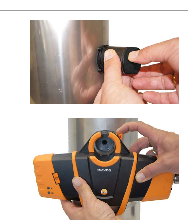
6 Using the product
18
2. Attach the probe mount to the flue gas duct by turning the fixing
ring clockwise.
3. Slide the measuring instrument onto the probe mount up to the
stop.
4. Check if the locking mechanism has latched into the probe
mount.
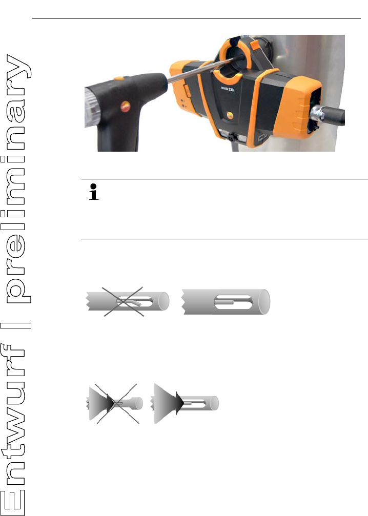
6 Using the product
19
5. Insert the flue gas probe through the probe mount into the flue
gas duct.
When using the testofix® probe mount, the measuring
instrument is exposed to heat radiating from the flue gas duct
during the measurement. In order to prevent consequently
affecting the combustion air temperature a AT probe with
cable must be used for the measurement!
6.2.1.6. Using the modular flue gas probe
Checking the thermocouple
The thermocouple of the flue gas probe must not lie against the
probe cage.
> Check before use. Bend the thermocouple back if necessary.
Aligning the flue gas probe
The flue gas must be able to flow freely past the thermocouple.
> Align the probe by turning it as required.
6 Using the product
20
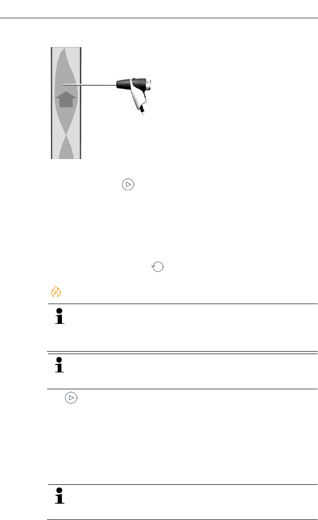
Searching for the centre of flow
The tip of the probe must be in the core current of the flue gas flow.
1. Corestream | .
2. Align the flue gas probe in the flue gas duct so that the tip is in
the core current (area of the highest flue gas temperature
Max FT).
- Grey value/grey pointer: Display of current flue gas temperature
- Orange value/orange pointer: Display of maximum flue gas
temperature
> Reset values/pointer: .
Pos: 34 /TD/Produkt ver wenden/testo 330ites to 330i Abgasmessung @ 17\ mod_1435137697977_79. docx @ 214452 @ 355 @ 1
6.2.2. | Flue gas
To achieve usable measurement results, the measurement
period of a flue gas measurement should be a minimum of
3 minutes and the measuring instrument should display
stable measured values.
If a separate measurement of CO undiluted has not yet
been carried out, this value is calculated using the readings
from the flue gas probe and is updated continuously.
1. .
- Readings are displayed.
If the Draught measurement parameter is activated in the reading
display, a draught measurement is automatically initiated in parallel
to the flue gas measurement. In the List measurement data
screen, the parallel draught measurement can be
stopped/restarted. This draught measurement is performed
separately to a measurement of the Draught measurement type.
For the draught measurement, the minus connection for
differential pressure measurements must be clear (ambient
pressure, not closed).
6 Using the product
21
> Tap the draught reading display or next to it.
2. .
Pos: 35 /TD/Produkt ver wenden/testo 330ites to 330i_Zugmessung @ 17\ mod_1435137966035_79. docx @ 214487 @ 355 @ 1
3.
6.2.3. | Draught
The minus connection for differential pressure
measurements must be clear (ambient pressure, not
closed).
1. .
- The reading is displayed.
The pressure sensor is continuously zeroed (every 10 s) to prevent
a drift during long measurements. The switching sound of the valve
can be heard during zeroing.
2. .
Pos: 36 /TD/Produkt ver wenden/testo 330ites to 330i BIMSCHV (LV DE) @ 17\ mod_1435144026625_79.doc x @ 214522 @ 3 @ 1
6.2.4. | BImSchV
Diese Messart ist nur verfügbar, wenn die Landesversion
Deutschland eingestellt ist.
Eine qA-Mittelwert-Messung kann durchgeführt werden. Dabei wird
kontinuierlich der Mittelwert über einen Zeitraum von 30 Sekunden
ermittelt, der Messtakt beträgt 1 Sekunde. Dargestellt werden die
aktuellen Mittelwerte zum jeweiligen Erfassungszeitpunkt.
✓ Eine Abgassonde und ein Verbrennungsluft-Temperaturfühler
müssen angeschlossen sein.
1. .
- Messung startet, sobald der der O2-Messwert unter 20% liegt.
Vor dem Beenden der Messung müssen die Messwerte stabil sein,
dies dauert typischerweise 2 bis 3 Minuten.
2. .
- Die qA-Messwerte (O2, AT, VT) und der Zug-Messwert werden
ermittelt (30s).
Pos: 39 /TD/Produkt ver wenden/testo 330ites to 330i CO unverdünnt @ 17\m od_1435144575689_79.d ocx @ 214557 @ 355 @ 1
6.2.5. | COundiluted
✓ A multi-hole probe (0554 5762) must be connected.
1. .
- The reading is displayed.
2. .
6 Using the product
22
Pos: 40 /TD/Produkt ver wenden/testo 330ites to 330i Rußzahl/WTT @ 17\mo d_1434442164943_79.doc x @ 213887 @ 3555 @ 1
6.2.6. | Smoke number
The values calculated by a smoke pump tester can be entered.
The parameters Smoke and Oil depos. are only available for oil
fuels.
Pos: 41 /TD/Produkt verwenden/testo 330i/t esto 330i Differenzdr uckmessung @ 18\mod_14 38358780132_79.doc x @ 217124 @ 355 @ 1
6.2.7. | Differential pressure
WARNING
Dangerous mixture of gases
Danger of explosion!
> Make sure there are no leaks between the sampling point and
the measuring instrument.
> Do not smoke or use naked flames during measurement.
✓ The gas pressure set (0554 1203) must be connected.
✓ The minus connection for differential pressure measurement
must be depressurised at the beginning of measurement
(ambient pressure; the instrument not connected to the system
being checked), as the pressure sensor is zeroed.
1. .
- Zeroing the pressure sensor.
- The reading is displayed.
2. Connect the instrument to the system being checked.
Do not measure for longer than 5 minutes, as the drift of the
pressure sensor could mean that the measured values are
outside the tolerance limits. Re-zero the pressure sensor for
longer measurements.
3. .
Pos: 42 /TD/Produkt ver wenden/testo 330i/t esto 330i Diff_Temper aturmessung @ 18\mod_14 38358778900_79.doc x @ 217089 @ 355 @ 1
6.2.8. | Differential temp.
✓ The differential temperature set (0554 1204) must be
connected.
1. .
- The measured values and the calculated differential
temperature ∆t (T1 - T2) are displayed.
2. .

6 Using the product
23
Pos: 43 /TD/Produkt ver wenden/testo 330i/t esto 330i O2 Zuluft @ 18\mod_ 1438358781318_79.doc x @ 217159 @ 3 @ 1
6.2.9. | O2 supply air
1. .
- The reading is displayed.
2. .
Pos: 44 /TD/Produkt ver wenden/testo 330i/t esto 330i Gasdurchsatz @ 19\ mod_1448542207252_ 79.docx @ 225997 @ 3 @ 4
6.2.10. | Differential temp.
✓ The differential temperature set (0554 1204) must be
connected.
1. .
- The measured values and the calculated differential
temperature ∆t (T1 - T2) are displayed.
2. .
Pos: 45 /TD/Produkt ver wenden/testo 330i/t esto 330i Öldurchsatz @ 19\mod_1448542436455_ 79.docx @ 226032 @ 3 @ 4
6.2.11. | Differential temp.
✓ The differential temperature set (0554 1204) must be
connected.
1. .
- The measured values and the calculated differential
temperature ∆t (T1 - T2) are displayed.
2. .
Pos: 46 /TD/Produkt ver wenden/testo 330i330i 6.x Messdaten drucken @ 17\mod_1435060959550_ 79.docx @ 214207 @ 355 @ 1
6.3. Printing readings
The current readings can be printed using a report printer
(accessories: Testo printer 0554 0621).
Making print text settings
The reading printout can be supplemented with individual
information (header: company address; footer: name of technician).
1. | Protocols | Own Company Data.
2. Make the settings.
A logo cannot be included in the reading printout. This is only used
for a report issued in PDF format.
Printing current readings
✓ The printer is switched on and within wireless range.
> | Print values.
6 Using the product
24
Pos: 47 /TD/Produkt ver wenden/testo 330i330i 6.x Protokoll @ 17\mod_1 435063502616_79.doc x @ 214382 @ 3 @ 1
6.4. Report
A report can be created of saved measurement data (readings) and
other information about the measurement.
Reports can be printed using a report printer (accessories: Testo
printer 0554 0621) or sent as a file attachment in an email. The
email application installed on the mobile terminal device is used for
this.
Pos: 48 /TD/Produkt ver wenden/testo 330i/33 0i 6.x.1 Zu Protokoll hi nzufügen @ 18\mod_143946 8867019_79.docx @ 21864 7 @ 3 @ 1
6.4.1. Add to protocol (save measurement)
The measurement data from the last measurement type carried out
are stored temporarily on the measuring instrument.
The clipboard is deleted when the measuring instrument
is switched off.
Measurements carried out can be saved to back up measurement
data and be used for a subsequent report:
> | Add to protocol.
The measurements are stored in the measuring instrument.
This memory is not suitable for use as a long-term
memory/archive! Generate a report of significant
measurements and save this in a suitable place.
Pos: 49 /TD/Produkt ver wenden/testo 330i/33 0i 6.x.2 Protokoll fer tigstellen @ 18\mod_1439 468920481_79.doc x @ 218717 @ 3 @ 1
6.4.2. Finish protocol
1. | Finish protocol.
or
| Protocols.
2. Open the input category:
3. Enter/select log data:
Category Description
Own
Company
Data
Reports can be supplemented with individual
information (company address; name of the
technician).
A logo can only be included when issued in PDF
format.
6 Using the product
25
Category Description
Format and
print Select version format(s):
• CSV (comma separated text file, e.g. for
Microsoft® Excel),
• PDF
• Print values (Testo printer 0554 0621 required
(accessories))
• ZIV (XML file, complying with the regulations of
the ‘Federal Association of Chimney Sweeps
Germany’).
Customer
data Enter contact details or Import Contact Data
(opens the application installed for contacts on the
mobile terminal device).
Comments
and pictures Enter comments (file name of log, comment,
measuring location name) and Add pictures (opens
the application installed for photos and videos on the
mobile terminal device).
Pictures are only included when issued in PDF
format.
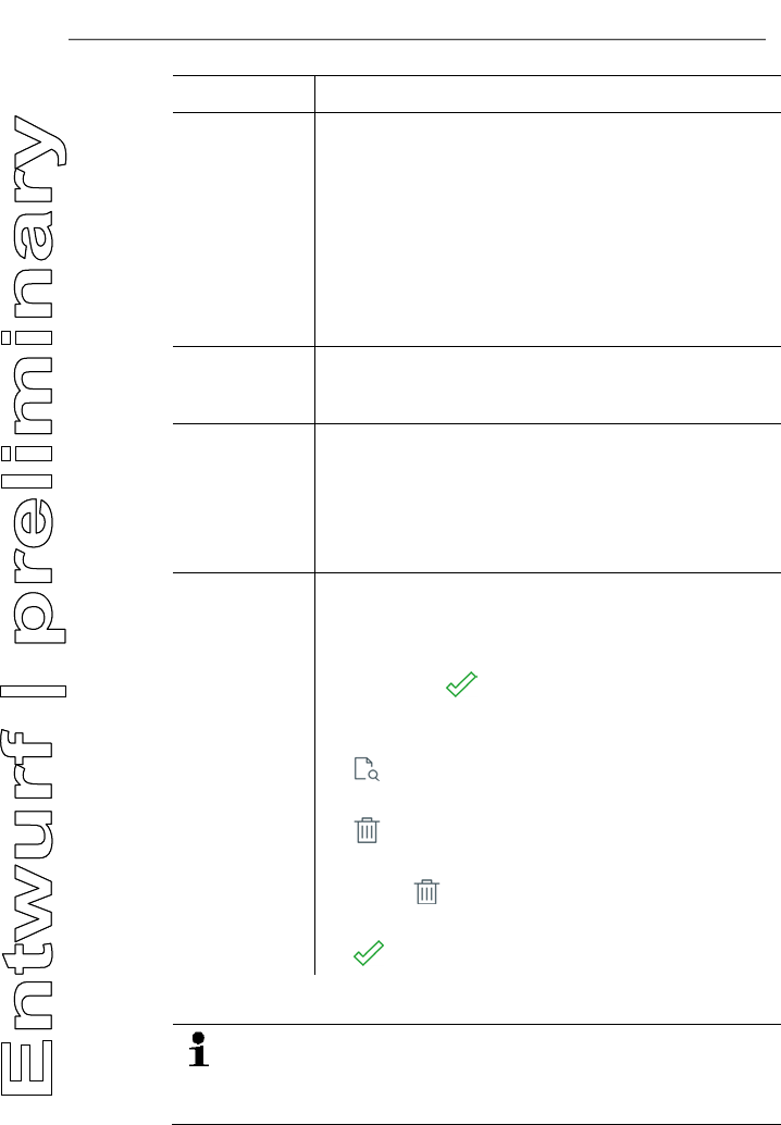
Select
measurement
s
All saved measurements are displayed in one of the
following time categories, depending on the creation
date: Today, Yesterday or Older.
The measurements selected to create the report are
identified with . New, saved measurements are
automatically identified.
To display saved readings to check them:
> .
To delete individual measurement:
> .
To delete all measurements of a time category:
> Touch next to the time category name.
To select/deselect a measurement for the report:
> .
All selected pictures and measurements are included in the
report. This means the report may reach a file size of several
megabytes. Before sending the report, check what your
mobile provider may charge for this!
7 Maintaining the product
26
4. Send.
Pos: 50 /TD/Überschr iften/7. Produkt ins tand halten @ 0\mod_1173789 831362_79.doc x @ 397 @ 2 @ 1
7 Maintaining the product
Pos: 51 /TD/Produkt ins tand halten/testo 330/ testo 330i Gerätezus tand prüfen @ 18\mod_1439538 650018_79.doc x @ 218941 @ 255 @ 1
7.1. Checking instrument status
7.1.1. | Instrument settings | Sensor diagnosis
The current status of the sensors can be displayed.
To change expended sensors, see Replacing sensors , page 31.
7.1.2. | Error list
Instrument errors that have not yet been rectified can be displayed.
Pos: 52 /TD/Produkt ins tand halten/testo 330/ testo 330i Instandha ltung_Messbox reinigen @ 18\mod_14376324980 59_79.docx @ 216102 @ 2 @ 1
7.2. Cleaning the measuring instrument
> If the housing of the measuring instrument is dirty, clean it with
a damp cloth. Do not use any aggressive cleaning agents or
solvents! Mild household cleaning agents and soap suds may
be used.
Pos: 53 /TD/Produkt ins tand halten/testo 330/ testo 330i_Instan dhaltung Kondensatbeh älter @ 18\mod_1437642496 381_79.docx @ 216137 @ 25 @ 1
7.3. Draining the condensate container
The fill level of the condensate container can be read from the
markings. Hold the instrument horizontally or vertically to check the
fill level.
The condensate consists of a weak mix of acids. Avoid skin
contact. Make sure that the condensate does not run over
the housing.
CAUTION
Condensate entering the gas path.
Damage to sensors and flue gas pump!
> Do not empty the condensate container while the flue gas
pump is in operation.
7 Maintaining the product
27
1. Open the condensate outlet on the condensate container.
2. Let the condensate run out into a sink.
3. Wipe off any drops still on the condensate outlet with a cloth
and close the condensate outlet.
The condensate outlet must be completely closed,
otherwise measuring errors could occur if external air gets
in.
Pos: 54 /TD/Produkt ins tand halten/testo 330/ testo 330i Gerät_oef fnen @ 18\mod_1437632106 827_79.docx @ 216067 @ 35 @ 1
7.4. Opening the measuring instrument
Open the measuring instrument only when this is required for
measuring purposes (gas sensors/replacing battery).
✓ The measuring instrument must not be connected to a mains
socket via the mains unit. The measuring instrument must be
switched off.
When opening/assembling the instrument, take care not to
lose any removed screws. Placing a cloth on the work top is
recommended.
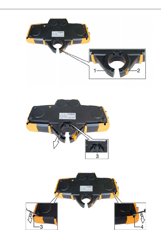
1. Lay the instrument face down so that the rear of the instrument
faces upwards and the side with the retaining bracket faces
you.
7 Maintaining the product
28
2. Use a cross-head screwdriver to remove the two (short) screws
(1 and 2) from the retaining bracket.
3. Move the catch hook outwards (3) and push the back of the
instrument up and lift off.
> If the back of the instrument cannot be removed by hand, this
can easily be levered out by applying a screwdriver to both of
the recesses 4 and 5.
7 Maintaining the product
29
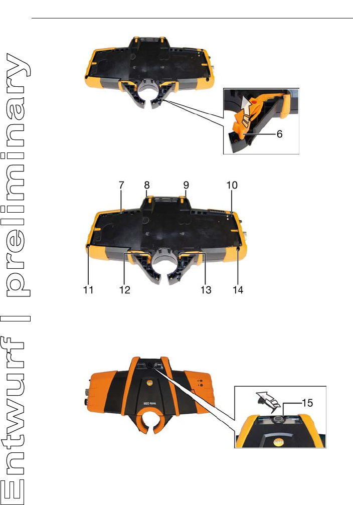
4. Remove the orange locking clips upwards out of the instrument
casing (6).
5. Use a cross-head screwdriver to loosen and remove the 4
screws 7 to 10 (short screws) and the 4 screws 11 to 14 (long
screws).
6. Turn the instrument over and place on its back so that the front
is facing upwards.
7. Remove the condensate trap sealing plug from the condensate
outlet (15).
7 Maintaining the product
30
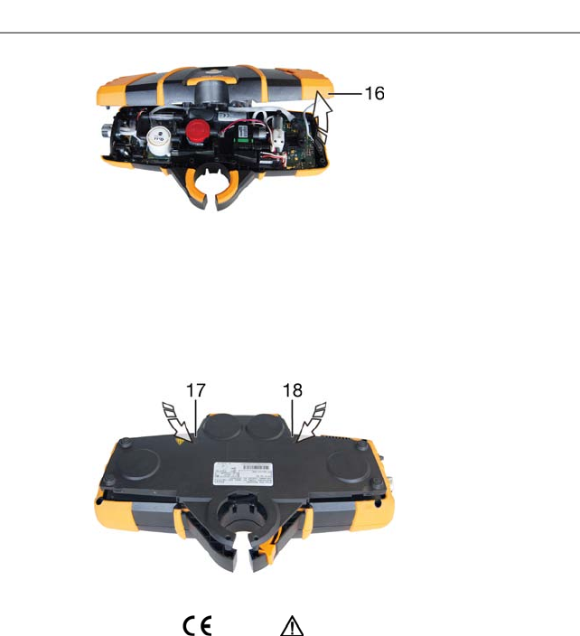
8. Fold up/back the upper instrument casing and place next to the
lower casing (16). Do this carefully to prevent damaging hoses
and lines.
Assembly
Perform in reverse order to assemble. Please note:
> Lay hoses and lines in the designated ducts.
> Make sure that hoses and lines do not get stuck.
> Insert the teeth on the lower edge of the back of the housing
into the lower instrument casing and push at the height of the
symbols (17) and (18) to lock into place in the housing.
Pos: 55 /TD/Produkt ins tand halten/testo 330/ testo 330i Akku wechse ln @ 18\mod_1437631105427_7 9.docx @ 216032 @ 3 @ 1
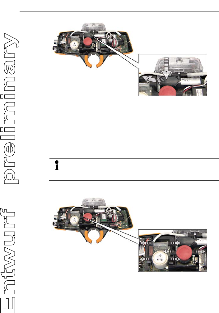
7.5. Replacing the rechargeable battery
✓ Measuring instrument is open; see Opening the measuring
instrument, page 27.
7 Maintaining the product
31
1. Open the battery lock: Press the grey button (1) and push to the
left keeping the button pressed (2).
2. Remove the battery and insert a new rechargeable battery. Use
only Testo rechargeable battery 0515 0107!
3. Close the battery lock: Press the grey button and push to the
right keeping the button pressed until the battery engages.
Pos: 56 /TD/Produkt ins tand halten/testo 330/ testo 330i Sensoren wechs eln @ 17\mod_1434444564 831_79.docx @ 213957 @ 2 @ 1
7.6. Replacing sensors
A slot bridge (0192 1552) must be inserted in slots which
are not equipped with a sensor. Used sensors must be
disposed of as hazardous waste!
✓ Measuring instrument is open; see Opening the measuring
instrument, page 27.
1. Disconnect the hose connections from the faulty sensor
(1)/bridge (2).
2. Remove the faulty sensor/bridge from the slot.
> For NO sensor: Remove the auxiliary circuit board.
7 Maintaining the product
32
Do not remove the auxiliary circuit board for the NO
sensor until immediately before installation. Do not
leave the sensor without auxiliary circuit board for
longer than 15 minutes.
3. Install new sensor/new bridge in the slot:
• Slot 1: O2 sensor
• Slot 2: CO sensor or COlow sensor
• Slot 3: NO sensor or NOlow sensor
4. Push the hose connections onto the sensor/bridge.
5. Close the measuring instrument.
When retrofitting a sensor, the associated measurement
parameter/unit must be enabled in the reading display.
Pos: 57 /TD/Produkt ins tand halten/testo 330 und t esto 350 neu/testo 330/ 350 Instandhaltung Ab gassonde reinigen @ 6\ mod_1270039302035_79. docx @ 60667 @ 2 @ 1
7.7. Cleaning the modular flue gas probe
✓ Disconnect the flue gas probe from the measuring instrument
prior to cleaning.
1. Release the probe catch by pressing the key on the probe
handle and remove the probe module.
2. Blow compressed air through the flue gas ducts in probe
module and probe handle (see illustration). Do not use a brush!
3. Fit a new probe module on the probe handle and engage it in
place.
Pos: 58 /TD/Produkt ins tand halten/testo 330/ testo 330 Sondenmodul wechseln @ 6\mod_12792631 31873_79.docx @ 66807 @ 2 @ 1
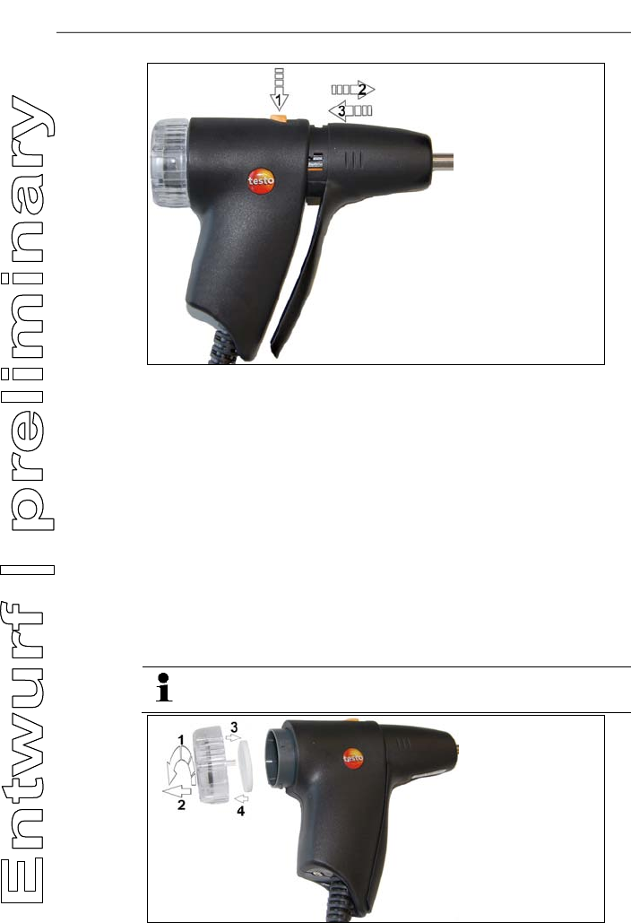
7.8. Replacing the probe module
✓ Disconnect the flue gas probe from the measuring instrument.
7 Maintaining the product
33
1. Press the button on the top of the probe handle (1) and remove
the probe module (2).
2. Plug in the new probe module and lock it in place (3).
Pos: 59 /TD/Produkt ins tand halten/testo 330/ testo 330 Instandhal tung Partikelfil ter prüfen @ 6\mod_12792655 18333_79.docx @ 66943 @ 255 @ 1
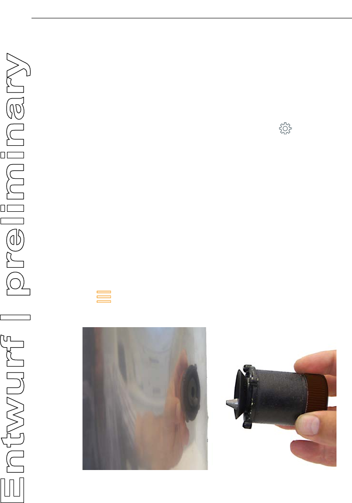
7.9. Checking/replacing the particle filter
Checking the particle filter:
Check the particle filter of the modular flue gas probe periodically
for contamination: check visually by looking through the window
of the filter chamber.
> If there is visible contamination or inadequate pump flow,
replace the filter.
Replacing the particle filter:
The filter chamber may contain condensate. This is not a
malfunction and will not cause wrong readings.
7 Maintaining the product
34
1. Open the filter chamber: turn slightly anti-clockwise (1). Remove
the filter chamber (2).
2. Remove the filter plate (3) and replace it with a new one (4
[0554 3385]).
3. Attach the filter chamber and lock it: turn slightly clockwise.
Pos: 60 /TD/Produkt ins tand halten/testo 330 und t esto 350 neu/testo 330/ 350 Instandhaltung Thermoelement wechseln @ 6\mod_1 270039469873_ 79.docx @ 60729 @ 2 @ 1
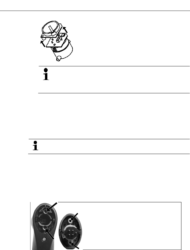
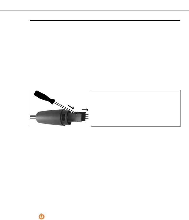
7.10. Changing the thermocouple
1. Release the probe catch by pressing the key on the probe
handle and remove the probe module.
2. Remove the thermocouple plug-in head from the socket using a
screwdriver and pull the thermocouple out of the probe shaft.
3. Keep inserting the new thermocouple into the probe shaft until
the connection head clicks into place.
4. Fit a new probe module on the handle and engage in place.
Pos: 61 /TD/Tipps und Hilf e/testo 330i Firm ware-Update @ 18\mod_14383592 71696_79.docx @ 217194 @ 2 @ 1
7.11. Updating the instrument software
At www.testo.com/download-center you can download the current
instrument software (firmware) for the testo 330i.
✓ The measuring instrument must be switched off.
1. Plug the measuring instrument mains unit into a mains socket.
2. Press and hold down for 10 s.
- Both status LEDs (blue/red) slowly flash alternately.
3. Insert the connecting cable (0449 0047) into the USB port on
the measuring instrument, then connect it to the PC.
- Your PC identifies the measuring instrument as a removable
medium.
4. Copy the new instrument software file (ap330ir.bin) to the
identified removable medium.
- Both status LEDs (blue/red) quickly flash alternately. This
process may take a few minutes.
5. Disconnect the connecting cable from the measuring
instrument.
- Once the instrument software has been updated, the measuring
instrument will automatically reboot and is ready for use again.
8 Technical data
35
Pos: 62 /TD/Überschr iften/9. Technische Da ten @ 18\mod_143799698380 4_79.docx @ 216246 @ 1 @ 1
8 Technical data
Pos: 63 /TD/Leistungsb eschreibung/Tec hnische Daten/testo 330 Technische Daten/ Zulassungen testo 330i (LV- spezifisch?) @ 17\ mod_1432805433483_ 79.docx @ 213340 @ 335555555 @ 4
8.1.1. Examinations and licenses
As declared in the Certificate of Conformity, this product complies
with Directive 2014/30/EU.
Testo 330i with gas sensors O2/CO, H2-compensated/NO,
combustion air temperature sensor, flue gas temperature sensor
and differential pressure sensor (draught) is TüV-tested in
accordance with VDI 4206.
The CO sensor 0393 0101 (CO, H2-compensated) is TÜV-tested in
accordance with EN 50379 part 2.
The CO sensor 0393 0051 (CO, not H2-compensated) is TÜV-
tested in accordance with EN 50379 part 3.
For official measurements in accordance with the 1st BImSchV
(chimney sweeps), the measuring instrument must be checked
every six months by a technical testing body of the Guild of Master
Chimney Sweeps or another testing body recognised by the
authorities.
8.1.2. Bluetooth® module
Feature Values
Type designation Stollmann E+V GmbH BlueMod+SR (August
2013)
Specification 4.0, Bluetooth® Classic/LowEnergy
Coverage < 10 m/< 32.8 ft.
Product note BlueMod+SR
Identification B021281
Company 44784
Certifications
European Certification
Belgium (BE), Bulgaria (BG), Denmark (DK), Germany (DE),
Estonia (EE), Finland (FI), France (FR), Greece (GR), Ireland (IE),
Italy (IT), Latvia (LV), Lithuania (LT), Luxembourg (LU), Malta (MT),
Netherlands (NL), Austria (AT), Poland (PL), Portugal (PT),

8 Technical data
36
Rumania (RO), Sweden (SE), Slowakia (SK), Slowenia (SI), Spain
(ES), Czech Republic (CZ), Hungary (HU), United Kingdom (GB),
Republic of Cypres (CY).
EFTA countries
Iceland, Liechtenstein, Norway and Switzerland.
Other countries
USA, Canada, Japan, Australia, New Zealand, Turkey
USA
Contains Transmitter Module FCC ID: RFRMSR
Product FCC ID: WAF-2016t330
Information from the FCC (Federal Communications Commission)
For your own safety
Shielded cables should be used for a composite interface.
This is to ensure continued protection against radio
frequency interference.
FCC warning statement
This equipment has been tested and found to comply with
the limits for a Class B digital device, pursuant to Part 15 of
the FCC Rules. These limits are designed to provide
reasonable protection against harmful interference in a
residential installation. This equipment generates, uses
and can radiate radio frequency energy and, if not installed
and used in accordance with the instructions, may cause
harmful interference to radio communications. However,
there is no guarantee that interference will not occur in a
particular installation. If this equipment does cause harmful
interference to radio or television reception, which can be
determined by turning the equipment off and on, the user is
encouraged to try to correct the interference by one or
more of the following measures:
• Reorient or relocate the receiving antenna.
• Increase the separation between the equipment and
receiver.
• Connect the equipment into an outlet on a circuit
different from that to which the receiver is connected.
• Consult the dealer or an experienced radio/TV
technician for help.
Caution
Changes or modifications not expressly approved by the
party responsible for compliance could void the user's
authority to operate the equipment. Shielded interface
cable must be used in order to comply with the emission
8 Technical data
37
limits.
Warning
This device complies with Part 15 of the FCC Rules.
Operation is subject to the following two conditions:
(1) this device may not cause harmful interference, and
(2) this device must accept any interference received,
including interference that may cause undesired operation.
Canada
Contains Transmitter Module IC ID: 4957A-MSR
Product IC ID: 6127B -2016T330
This instrument complies with Part 15C of the FCC Rules
and Industry Canada RSS-210 (revision 8). Commissioning
is subject to the following two conditions:
(1) This instrument must not cause any harmful interference
and
(2) this instrument must be able to cope with interference,
even if this has undesirable effects on operation.
Cet appareil satisfait à la partie 15C des directives FCC et
au standard Industrie Canada RSS-210 (révision 8). Sa
mise en service est soumise aux deux conditions suivantes :
(1) cet appareil ne doit causer aucune interférence
dangereuse et
(2) cet appareil doit supporter toute interférence, y compris
des interférences qui provoquerait des opérations
indésirables.
Japan
Australia
E 1561
Turkey
Authorized.

8 Technical data
38
Pos: 64 /TD/Leistungsb eschreibung/Techni sche Daten/testo 330 Technische Daten/ Messbereiche_Genauigkei ten testo330i @ 17\ mod_1434361470830_79. docx @ 213677 @ 33 @ 1
8.1.3. Measuring ranges and resolution
Measurement
parameter Measuring range Resolution
O2 0 to 21 vol.% 0.1 vol.%
CO 0 to 4,000 ppm 1 ppm
CO
(H2-compensated) 0 to 8,000 ppm 1 ppm
CO
(H2-compensated)
with fresh air
dilution
0 to 30,000 ppm 1 ppm
COlow 0 to 500 ppm 0.1 ppm
NO 0 to 3,000 ppm 1 ppm
CO environment
(via flue gas
probe)
0 to 2,000 ppm 1 ppm
Draught -9.99 to 40 hPa 0.01 hPa
∆P 0 to 300 hPa 0.1 hPa
Temperature -40 to 1,200 °C 0.1 °C (-40.0 to 999.9 °C)
1 °C (rest of range)
Efficiency 0 to 120% 0.1%
Flue gas loss 0 to 99.9% 0.1%
CO2 determination
(calculation from
O2)
Display range 0 to
CO2max 1 ppm
8.1.4. Accuracy and response time
Measurement
parameter Accuracy Response
time
O2 ± 0.2 vol.% < 20 s (t90)
CO ± 20 ppm (0 to 400 ppm)
± 5% of m.v. (401 to 2,000 ppm)
± 10% of m.v. (2,001 to
4,000 ppm)
< 60 s (t90)

8 Technical data
39
Measurement
parameter Accuracy Response
time
CO H2-
compensated ± 10 ppm or ± 10% of m.v.1 (0 to
200 ppm)
± 20 ppm or ± 5% of m.v.1 (201
to 2,000 ppm)
± 10% of m.v. (2,001 to
8,000 ppm)
< 60 s (t90)
CO (H2-
compensated)
with fresh air
dilution
± 200 ppm or ± 20% of m.v.1 (0
to 30,000 ppm) < 60 s (t90)
COlow ± 2 ppm (0 to 39.9 ppm)
± 5% of m.v. (rest of range)
< 40 s (t90)
NO ± 5 ppm (0 to 100 ppm)
± 5% of m.v. (101 to 2,000 ppm)
± 10% of m.v. (2,001 to
3,000 ppm)
< 30 s (t90)
Draught ± 0.02 ppm or ± 5% of m.v.1 (-
0.50 to 0.60 hPa)
± 0.03 hPa (0.61 to 3.00 hPa)
± 1.5% of m.v. (3.01 to
40.00 hPa)
-
∆P ± 0.5 hPa (0.0 to 50.0 hPa)
± 1% of m.v. (50.1 to 100.0 hPa)
± 1.5% of m.v. (rest of range)
-
Temperature ± 0.5 °C (0.0 to 100.0 °C)
± 0.5% of m.v. (rest of range)
depending on
the probe
Efficiency - -
Flue gas loss - -
CO2
determination
(calculation from
O2)
± 0.2 vol.% -
1 higher value is valid

8 Technical data
40
Pos: 65 /TD/Leistungsb eschreibung/Techni sche Daten/testo 330 Technische Daten/ weitere Gerätedaten test o 330i @ 17\mod_143280582 6557_79.docx @ 213410 @ 35 @ 1
8.1.5. Other instrument data
Flue gas analyzer
Feature Values
Storage and
transport
temperature
-20 to 50 °C
Operating
temperature -5 to 45 °C
Max. surface
temperature at the
measurement
aperture (with probe
mount)
140 °C
Ambient humidity 0 to 90% RH, non-condensing
Operating positions No restriction
Fill level of
condensate trap 9 ml
Corresponds with a service life of approx.
5 h (EL heating oil)/approx. 2.5 h (natural
gas) at 20 °C ambient temperature)
Power supply Li Ion battery: 3.7 V/2.6 Ah
Mains unit: 6 V/2.0 A
Protection class IP 40
Weight 720 g (excluding battery)
Dimensions 270 x 160 x 57 mm
Memory 500,000 individual readings
Flue gas
overpressure
max. 50 mbar
Negative pressure max. 80 mbar
Rechargeable
battery charging
temperature
± 0 to 35 °C
Rechargeable
battery charge time approx. 5-6 h
Rechargeable
battery life 6 h (pump on, 20 °C ambient temperature)

8 Technical data
41
Feature Values
Warranty Measuring instrument: 48 months
Sensors O2, CO: 48 months
Other sensors: 24 months
Flue gas probe: 48 months
Thermocouple: 12 months
Rechargeable battery: 12 months
Further warranty terms: see website
www.testo.com/warranty
8 Technical data
42
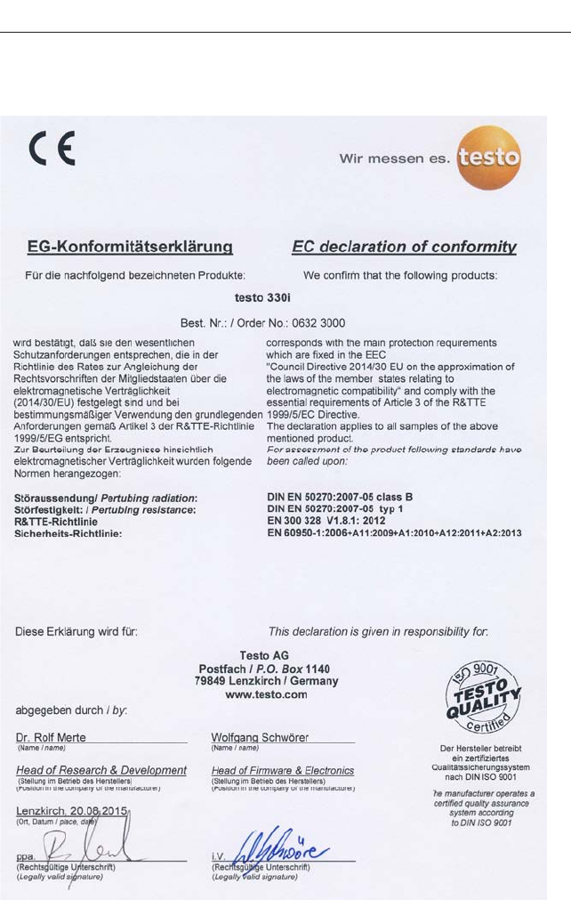
Pos: 66 /TD/Leistungsb eschreibung/Tec hnische Daten/testo 330 Technische Daten/Konf ormitätserkläru ng testo 330i @ 17\mod_143280 5698761_79.d ocx @ 213375 @ 3 @ 1
8.1.6. Declaration of conformity
9 Tips and assistance
43
Pos: 67 /TD/Überschr iften/8. Tipps und Hilfe @ 0\ mod_1173789887985 _79.docx @ 406 @ 2 @ 1
9 Tips and assistance
Pos: 68 /TD/Überschr iften/8.1 Fragen und Ant worten @ 0\mod_117740201 7078_79.docx @ 1093 @ 2 @ 1
9.1. Questions and answers
Pos: 69 /TD/Tipps und Hilf e/Fragen und Antworten/ testo 330i Fragen und An worten @ 18\mod_14383594 16497_79.docx @ 217229 @ 2 @ 1
Question Possible causes/solution
Rechargeable battery low > Switch to mains operation.
Measuring instrument
switches off automatically
or cannot be switched on
Rechargeable battery has run out:
> Charge rechargeable batteries or
switch to mains operation.
Displayed battery capacity
seems to be faulty Rechargeable battery was repeatedly
not fully discharged/charged:
> Discharge rechargeable battery
(until measuring instrument
switches off automatically) and
then charge fully.
Error message: Main
pump flow is too high Gas outlet blocked:
> Make sure that the gas outlet is
clear.
Overpressure in flue gas duct too high
(> 50 mbar):
> Perform draught measurement.
Error message: Sensor
protection is active The switch-off threshold of the CO
sensor was exceeded:
> Remove probe from flue gas duct.
Error message: Printing
not possible
> Switch on printer.
> Move printer into wireless range.
Three acoustic signals
after switching on the
measuring instrument
Device error:
> Consult Testo Service or your
dealer.
App no longer responds to
command inputs
> Open the overview of active
applications (refer to your
smartphone operating system
instructions) and close the App.
Instrument no longer
responds to command
inputs
> Keep the button pressed down for
10 s to reset and reboot the
measuring instrument.

9 Tips and assistance
44
Question Possible causes/solution
It cannot establish a
Bluetooth connection!
or
Required instrument is not
in the Find Device display.
> Keep the button pressed down for
10 s to reset and reboot the
measuring instrument.
No instruments are shown
in the Find Device display.
> Check the Bluetooth settings on
the mobile terminal device.
> Switch Bluetooth off and on again
on the mobile terminal device.
Connection fails repeatedly
with a Bluetooth® error
message.
1. Keep the button pressed down for
10 s to reset and reboot the
measuring instrument.
2. Switch Bluetooth off and on again
on the mobile terminal device. If
necessary: switch the mobile
terminal device off and on again.
When using two printers:
The required printer not
found!
The mobile terminal device may be
connected to the other printer and this
connection is saved in the App.
> Close the App and restart it to
establish a new connection.
In Excel® the CSV format
is not displayed properly.
Open Excel® and create a new
template. Click on the Data tab and
activate the From Text menu. Select
the CSV file and adopt in the Excel
template.
If we have not been able to answer your question, please contact
your dealer or Testo Customer Service. For contact details, please
visit www.testo.com/service-contact.
Pos: 70 /TD/Überschr iften/8.3 Zubehör und Er satzteile @ 0\mod_117740 2058734_79.doc x @ 1102 @ 2 @ 1
9.2. Accessories and spare parts
Pos: 71 /TD/Tipps und Hilf e/Zubehör und Ersatzt eile/testo 330i Zubehör _Ersatzteile @ 17\m od_1434444889185_79.d ocx @ 213992 @ 55555555 @ 1
Printer
Description Article no.
Bluetooth®/IRDA printer, incl. mains unit 5 V/1.0 A
with micro USB cable 0554 0621
Mains unit 5 V/1.0 A with micro USB cable 0554 1105
9 Tips and assistance
45
Description Article no.
Spare thermal paper for printer (6 rolls) 0554 0568
Modular flue gas probes
Description Article no.
Modular flue gas probe 180 mm, 500 °C, probe shaft
diameter: 8 mm, hose 0.6 m 0600 9780
Modular flue gas probe 300 mm, 500 °C, probe shaft
diameter: 8 mm, hose 0.6 m 0600 9781
Modular flue gas probe 180 mm, 500 °C, probe shaft
diameter: 6 mm, hose 0.6 m 0600 9782
Modular flue gas probe 300 mm, 500 °C, probe shaft
diameter: 6 mm, hose 0.6 m 0600 9783
Modular flue gas probe 180 mm, 500 °C, probe shaft
diameter: 8 mm, hose 2.2 m 0600 9760
Modular flue gas probe 300 mm, 500 °C, probe shaft
diameter: 8 mm, hose 2.2 m 0600 9761
Flexible flue gas probe 330 mm, Tmax. 180 °C, short-
term 200 °C, bending radius max. 90° for
measurements in difficult to access locations
0600 9770
Probe modules/accessories for modular flue gas probes
Description Article no.
Probe shaft module 180 mm, 500 °C, thermocouple
0.5 mm, probe shaft diameter: 8 mm 0554 9760
Probe shaft module 300 mm, 500 °C, thermocouple
0.5 mm, probe shaft diameter: 8 mm 0554 9761
Spare thermocouple for module 0554 9760,
0554 9762 0430 9760
Spare thermocouple for module 0554 9761,
0554 9763 0430 9761
Probe mount testofix®, 8 mm 0554 3006
Cone, 8 mm, steel 0554 3330
Multi-hole probe shaft, length 300 mm, Ø 8 mm, for
CO mean value calculation 0554 5762
Multi-hole probe shaft, length 180 mm, Ø 8 mm, for
CO mean value calculation 0554 5763

9 Tips and assistance
46
Description Article no.
Flexible probe shaft module 0554 9770
Hose extension; 2.8 m; extension line probe-
instrument 0554 1202
Particle filter, 10 pcs. 0554 3385
Temperature probe
Description Article no.
Combustion air temperature (AT) probe, 300 mm 0600 9791
Combustion air temperature (AT) probe, 190 mm 0600 9787
Combustion air temperature (AT) probe, 60 mm 0600 9797
Fast reaction surface probe 0604 0194
Mini ambient air probe 0600 3692
Other probes
Description Article no.
O2 dual wall clearance probe 0632 1260
Gas leak probe 0632 3330
Differential temperature set, 2 pipe wrap probes,
adapter 0554 1204
Smoke pump tester, incl. oil, soot plates, for
measuring soot in flue gas 0554 0307
Retrofit/spare sensors
Description Article no.
O2 sensor 0393 0002
CO sensor 0393 0051
CO sensor H2-compensated 0393 0101
COlow sensor 0393 0103
NO sensor 0393 0151
NOlow sensor on request
9 Tips and assistance
47
Cases
System case with double floor (height:180 mm) for
instrument, probes and accessories 0516 3302
System case (height: 130 mm) for instrument,
probes and accessories 0516 3303
System case with tool bag without content 0516 0329
Other accessories
Description Article no.
Mains unit 0554 1096
Spare rechargeable battery 0515 0107
Instrument/PC connecting cable 0449 0047
EasyHeat (PC configuration software) 0554 3332
Additional filter 0133 0010
Flue draught set 0554 3150
Fine pressure probe 0638 0330
Set of capillary hoses 0554 1215
Solid fuel measurement module with adapter and
probe shaft with sintered filter 0600 9765
Sintered filter for solid fuel measurement probe shaft 0133 0035
Filter material for condensate trap on solid fuel
measurement adapter 0133 0012
NOx filter 0554 4150
Pressure test set for gas pipe testing 0554 1213
Straight Pitot tube 0635 2050
ISO calibration certificate for flue gas 0520 0003
For a complete list of all accessories and spare parts, please refer
to the product catalogues and brochures or visit our website
www.testo.com
=== Ende der Liste für Textmarke Inhalt ===

0971 3340 en 02a en-GB