Texa S p A DP15 VEHICLE DIAGNOSTIC SYSTEM User Manual
Texa S.p.A. VEHICLE DIAGNOSTIC SYSTEM
User Manual


2

SUMMARY
Review of the Manual...............................................................................5
INTRODUCTION......................................................................................6
1 ABOUT THE MANUAL........................................................................7
2 LEGEND OF THE SYMBOLS USED..................................................8
3 GLOSSARY........................................................................................9
4 SAFETY RULES...............................................................................10
4.1 General Rules......................................................................................10
4.2 User Safety...........................................................................................10
4.3 Vehicle Safety......................................................................................10
4.4 Device Safety.......................................................................................11
5 OPERATION OF THE RADIO DEVICES..........................................13
6 REGULATORY INFORMATION.......................................................14
7 DATAPLUG.......................................................................................15
8 DESCRIPTION..................................................................................16
9 POWER SUPPLY ............................................................................17
10 LOCATION OF THE DIAGNOSTIC SOCKET................................18
11 INSTALLATION AND CONFIGURATION.......................................19
11.1 Installation..........................................................................................19
11.2 Configuration......................................................................................21
12 USE.................................................................................................22
13 MAINTENANCE..............................................................................23
14 BLINK CODES................................................................................24
15 TROUBLESHOOTING....................................................................25
16 TECHNICAL FEATURES ...............................................................27
17 ENVIRONMENTAL INFORMATION (For the European Union)
...............................................................................................................29
3
en

4

DATAPLUG TECHNICAL MANUAL
Review of the Manual
This document is review 02 of the DataPlug technical manual.
5
en

INTRODUCTION
Dear Driver,
thank you for choosing a TEXA product for your vehicle, we are sure that you
will be completely satisfied with it.
Thanks to this product you will be able to obtain information in real time directly
from your vehicle's engine control unit; this way, using it in a safer and more
efficient way other than interacting in a more effective way with your mechanic
by reporting (in case of malfunctions) what the product detects.
Please read the instructions in this manual carefully and keep it for future
reference.
Reading and understanding the following manual will help you to avoid damage
or personal injury caused by improper use of the product.
We remind you that the manual has the sole purpose to illustrate the product's
functioning and that you must refer to qualified personnel for any repair on the
vehicle on which the product is installed.
TEXA S.p.A reserves the right to make any changes deemed necessary to
improve the manual for any technical or marketing requirement; the company
may do so at any time without prior notice.
This manual is to be considered an essential part of the product it refers to. If it
is resold, the original buyer is therefore required to forward the manual to the
new owner.
Reproduction, partial or whole, of this manual in any form without written
authorisation by the manufacturer is strictly forbidden.
© copyright and database rights 2015.The material contained in this
document is protected by copyright and database rights. All rights are reserved
according to Law and international agreements.
© 2015 TEXA S.p.A. All rights reserved. TEXA is a TEXA S.p.A. trademark
registered in Italy and other countries
6

1 ABOUT THE MANUAL
This manual is divided into the following chapters:
1. Legend of the symbols used in the manual: it gives indications regarding the
symbols used in this document.
2. Glossary: it clears the meaning of some terms used in this document.
3. Safety: it gives important indications for the safety of the user, the vehicle and of
the device this document refers to.
4. Operation of the radio devices: it gives important information regarding the
radio devices that are equipped on the device this document refers to.
5. Regulatory information: it gives indications regarding the laws that are applied
to the device this document refers to.
6. DataPlug: it gives a brief overview of the device this document refers to.
7. Description: it describes the main features of the device this document refers to.
8. Power supply: it explains how the device this document refers to is powered.
9. Location of the diagnostic socket: it explains how to find the diagnostic socket
needed to connect the device this document refers to.
10. Installation and configuration: it explains how to install and configure the device
this document refers to.
11. Use: it explains how to use the device this document refers to.
12. Maintenance: it explains how to take care of the device this document refers to.
13. Blink codes: it explains how to read the flashing of the LEDs of the device this
document refers to.
14. Troubleshooting: it gives some situations / problems that can occur while using
the device this document refers to, along with a possible cause and a possible
solution.
15. Technical features: it gives the main technical features of the device this
document refers to.
16. Environmental information: it gives the information related to the disposal of
the device this document refers to.
7
en
2 LEGEND OF THE SYMBOLS USED
The symbols used in the manual are described in this chapter.
Asphyxiation Risk
Explosion Risk
High Voltage Hazard
Fire / Burn risk
Poisoning Hazard
Corrosive Substances Risk
Noise Hazard
Moving Parts Risk
Crushing Risk
General Risk
Important information
8

3 GLOSSARY
•Device: the term refers to DataPlug.
•Coverage list: official document that indicates only the vehicles on which you
can safely install the device.
•Pairing: mutual recognition process that takes place when two Bluetooth devices
must establish communication for the first time. It could require you to enter an
identification code (PIN).
•OBD socket / diagnostic socket: vehicle connector that allows you to connect
to the vehicle's control unit.
•Display unit: any smartphone in which the app that allows the connection with
DataPlug is installed.
9
en
4 SAFETY RULES
The technology used for the design and manufacturing control of the DataPlug
makes it a reliable, simple and safe device to use.
Users of DataPlug are required to follow the general safety rules, to use the
device for its intended use only and to take care of it as indicated in this manual.
4.1 General Rules
•The user must have carefully read all the information and instructions indicated
in the technical documents provided with the device.
•Consult an authorised workshop for any doubts regarding how to carry out the
installation properly.
4.2 User Safety
The device was designed and created in order to allow an easy, fast
and safe installation; nevertheless, it is impossible to completely
eliminate some of the risks connected to this operation.
Safety Measures:
•Make sure the vehicle's instrument panel is off before starting the installation.
•Make sure the vehicle on which you wish to install the device is on a flat surface
and with the parking brake engaged.
•Make sure there are not any damaged cables around the diagnostic socket.
•Be careful not to harm yourself on sharp plastic edges or metal plates around the
diagnostic socket.
The position in which the device is placed and the behaviour of its LEDs
were designed to avoid any possible obstacle or interference for the
driver.
Lack of concentration while driving puts both the driver and the vehicle
in danger.
Safety Measures:
•Do not drive the vehicle before reassembling the plastic parts and panels
previously removed.
•Do not get distracted by checking the status of the device or interacting with it
directly or using the display unit.
4.3 Vehicle Safety
The device was designed and created in order to allow an easy, fast
and safe installation; nevertheless, it is best to be sure not to
compromise any vehicle function during this operation.
10
Safety Measures:
•Delicately remove any plastic part, cover or bulkhead that might cover the
diagnostic socket, being careful not to loose any screw or fastening hook.
•Be careful not to damage or disconnect any plastic part or cable close to the
diagnostic cable.
•Carefully reposition and close any plastic part, cover or bulkhead at the end of
the device's installation and configuration phase.
•Do not install the device in vehicles that are not expressly indicated in the specific
coverage list.
4.4 Device Safety
The device was designed to be used in specific environmental
conditions.
Using the device in environments with temperatures and humidity that
differ from those specified, may impair its efficiency.
Safety Measures:
•Always place the device in a dry area.
•Do not expose or use the device close to heat sources.
•Position the device in order to guarantee its proper ventilation.
•Do not use corrosive chemicals, solvents or harsh detergents to clean the device.
The device was created to be mechanically resistant and suitable for
the use it was designed for.
Careless use and excessive mechanical strain may impair its
efficiency.
Safety Measures:
•Do not drop, shake or knock the device.
•Do not carry out any type of intervention that may damage the device.
•Do not open or disassemble the device.
•Do not force the device or the connectors and take the utmost care during all
connecting and disconnecting operations.
•Connect the device properly and securely in order to avoid it from accidentally
disconnecting during use.
•Do not use screwdrivers or other tools to lever and disconnect the device.
The device was manufactured to be electrically safe and to work with
specific supply voltage levels.
Failure to comply with the specifications related to the power supply
may impair the device's efficiency.
Safety Measures:
11
en

•Do not wet the device with water or other liquids.
•If not specified otherwise, use the device on vehicles with a 12 V DC power supply
and chassis connected to the negative pole and in ant case only on the supported
vehicles.
•The connection for the device's power supply must always be with the battery-
operated system of the vehicle being tested.
The electromagnetic compatibility tests carried out on the device
guarantee that it can be adapted to the technologies normally used on
vehicles (ex.: engine control, ABS, airbag, etc.). Nevertheless, if
malfunctions occur, contact the vehicle's dealer.
12

5 OPERATION OF THE RADIO DEVICES
Wireless connection with Bluetooth® technology
The wireless connection with Bluetooth technology is a technology that supplies
a standard and reliable method to exchange information between different
devices, using radio waves. Products such as cellular phones, portable devices,
computers, printers, cameras, pocket PCs etc. use this type of technology.
The Bluetooth interface searches for compatible electronic devices according
to the radio signal they generate and establishes a connection between them.
The tools operate a selection suggesting only compatible / enabled devices.
This does not exclude the presence of other sources of communication or
interference.
THE EFFICIENCY AND THE QUALITY OF THE BLUETOOTH
COMMUNICATION MAY BE INFLUENCED BY THE PRESENCE OF RADIO
DISTURBANCE SOURCES. THE COMMUNICATION PROTOCOL HAS
BEEN DEVELOPED TO MANAGE THESE TYPES OF ERRORS; HOWEVER,
IN THESE CASES COMMUNICATION MAY BECOME DIFFICULT AND
CONNECTION MAY REQUIRE SEVERAL ATTEMPTS.
SHOULD THE WIRELESS CONNECTION ENCOUNTER SERIOUS
PROBLEMS THAT MAY COMPROMISE A REGULAR COMMUNICATION,
THE SOURCE OF THE ENVIRONMENTAL ELECTROMAGNETIC
INTERFERENCE MUST BE IDENTIFIED AND ITS INTENSITY REDUCED.
Position the product in order to guarantee the correct operation of its radio
devices. In particular, do not cover it with any shielding or metal materials in
general.
13
en

6 REGULATORY INFORMATION
Declaration of Conformity
Texa S.p.A. hereby declares that this DataPlug complies with the
essential requirements and with all further provisions defined by the
R&TTE 1999/5/EC and RoHS 2011/65/EU directives.
A complete copy of the Declaration of Conformity can be found at
Texa S.p.A., Via 1 Maggio 9, 31050 Monastier di Treviso (TV), Italy
14
Conformity
The DataPlug complies with the following reequirements:
- FCC (Federal Communications Commission) Part 15
Operation is subject to the following two conditions:
(1) This device may not cause harmful interference, and
(2) This device must accept any interference received, including interference
that may cause undesired operatio.
Changes or modification not expressly approved by the party responsible for
compliance could void the user’s authority to operate the equipment.
FCC ID: T8RDP15

7 DATAPLUG
DataPlug is a compact device that, during normal vehicle operation, can
acquire information useful both to the driver and the mechanic.
The data acquired is useful to detect problems connected to the vehicle's
management and its maintenance status.
The device can be installed on any Volkswagen vehicle that is in the
specific coverage list.
The device must be connected to a specific diagnostic socket called OBD
socket.
The device communicates with the vehicle's control unit through the OBD
socket and acquires the required data.
The device is able to acquire the required data from the vehicle and to transmit
it in real time via Bluetooth to the smartphone selected as a display unit.
For this to occur, a specific app must be installed in the display unit.
The app can be downloaded directly from Internet through and
.
The acquired data is processed and displayed on the display unit.
Connecting and disconnecting the device from the vehicle is quick and easy.
Because of its small size, the device takes up little space and does not interfere
with driving.
15
en
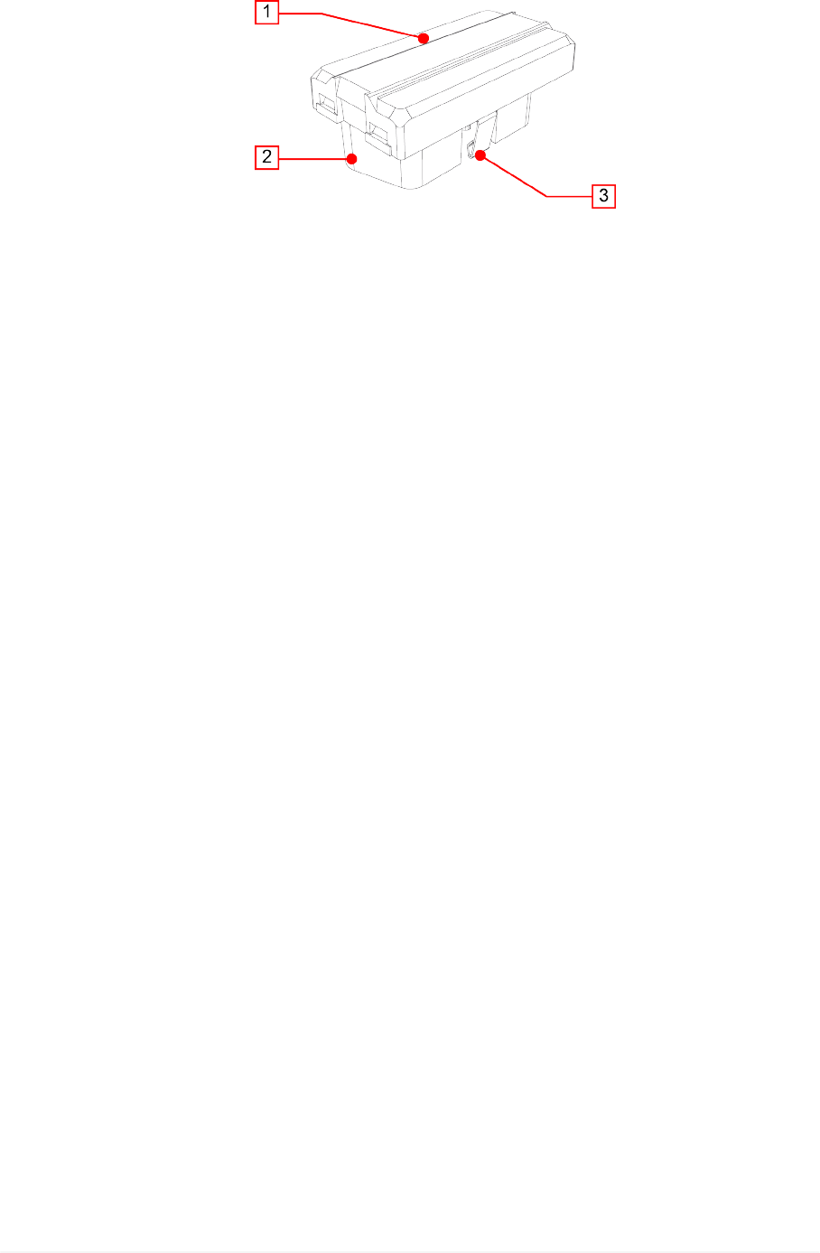
8 DESCRIPTION
This chapter describes the general features of the device.
1. Status LEDs: they give indications regarding the status of the device.*
•Green: indicates the status of the device without Bluetooth communication.
•Blue: indicates the status of the device with Bluetooth communication.
•Red: indicates the presence of errors.
2. OBD connector: it allows the connection between the device and the vehicle's
diagnostic socket and, through the latter, to the control unit.
3. Retention hook: it secures the device to the vehicle's diagnostic socket.
(*) For more information consult the chapter Blink Codes.
16

9 POWER SUPPLY
The device draws its power supply directly from the battery of the vehicle it is
connected to through the OBD socket.
The vehicle's OBD socket is always powered, even when the engine and
instrument panel are off.
The absorption never affects the battery's charge.
17
en
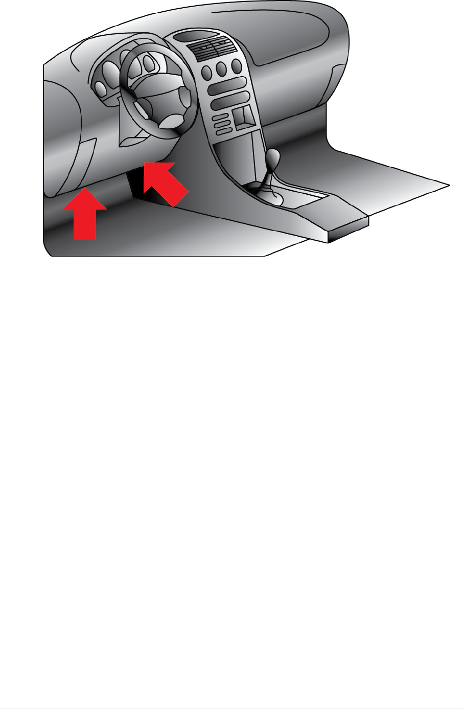
10 LOCATION OF THE DIAGNOSTIC SOCKET
The image below indicates where the diagnostic socket may be located.
We always recommend you check the location of the OBD socket in the
vehicle's user manual.
In case of doubts or for further information, contact the Technical Assistance or
your Service Partner / Retailer.
18

11 INSTALLATION AND CONFIGURATION
The following chapters illustrate how to install and configure the device.
The device can be installed only on Volkswagen vehicles indicated in the
specific coverage list.
Do not install the device on vehicles not expressly indicated in the
specific coverage list.
11.1 Installation
A screwdriver may be needed to loosen the screws that fasten the
panels that cover the OBD socket.
Proceed as follows:
1. Turn off the vehicle (ignition key off).
2. Locate the OBD socket.
3. Carefully remove any panels cover the OBD socket.
4. Connect the device to the OBD socket.
5. Turn on the vehicle (instrument panel on).
6. Make sure the device is securely connected to the diagnostic socket to avoid
it from accidentally disconnecting during use.
Make sure that the various components around the diagnostic
socket do not damage the device during installation.
Make sure that the position of the device does not interfere with
driving.
19
en
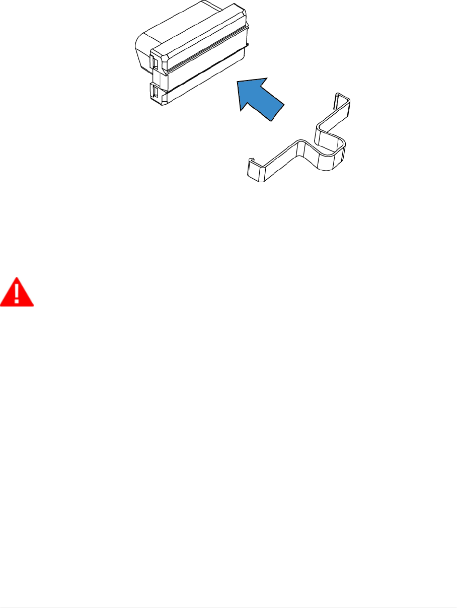
You might have to disconnect the device form the OBD socket during vehicle
maintenance operations in order to allow the connection of diagnostic devices.
In this case, use the specific extractor tool.
Proceed as follows:
1. Turn off the vehicle (ignition key off).
2. Carefully remove any panels cover the OBD socket.
3. Apply the extractor tool to the device.
4. Carefully pull out the device until it disconnects completely from the
diagnostic socket.
If you do not have the extractor tool, use your bare hands to carry out this
operation.
Do not use screwdrivers or other tools to lever and disconnect the
device.
20

11.2 Configuration
The configuration of the vehicle is automatic, nevertheless you should verify the
connection to the control unit and to the display unit by means of the flashing
LEDs before repositioning plastic parts or panels.
After the check, reposition all the plastic parts and panels previously removed.
Do not start driving before the plastic parts and panels removed are
repositioned correctly.
DISPLAY UNIT'S BLUETOOTH NOT ACTIVE
Proceed as follows:
1. Turn on the vehicle's instrument panel.
2. Make sure the device's green LED goes through the following statuses:
Double flash Configuration in progress.
Quick flash Device configured, waiting to communicate with the vehicle.
Slow flash Device configured and communicating with the vehicle.
Normal operation.
At this point the device is ready for use.
DISPLAY UNIT'S BLUETOOTH ACTIVE
Proceed as follows:
1. Make sure the display unit's Bluetooth is active.
2. Turn on the vehicle's instrument panel.
3. Make sure the device's green and blue LED flashes alternately.
4. Launch the specific app for the connection to the device.
5. Start the procedure for the connection to the device.
6. Enter the PIN when requested by the app (the PIN is printed on the device's label
and on a sticker applied to the product's box).
7. Make sure the device's blue LED goes through the following statuses:
Double flash Configuration in progress.
Quick flash Device configured, waiting to communicate with the vehicle.
Slow flash Device configured and communicating with the vehicle.
Normal operation.
At this point the device is ready for use.
For further information consult the Blink Codes chapter.
21
en

12 USE
It is no longer required to act directly on the device after the installation and
configuration.
Any operation takes place through the display unit.
The device activates as soon as the vehicle's instrument panel is turned on and
it connects automatically to the display unit if it is within the operating range of
the device's Bluetooth antenna.
All the device's LEDs turn off automatically as soon as the vehicle starts moving.
While driving, do not get distracted by checking the status of the
device or interacting with it directly or using the display unit.
In case of doubts or for further information, contact the Technical Assistance or
your Service Partner / Retailer.
22

13 MAINTENANCE
This product does not require maintenance operations.
Follow the indications in this manual carefully in order to guarantee an extended
use of the device.
In case of doubts or for further information, contact the Technical Assistance or
your Service Partner / Retailer.
23
en

14 BLINK CODES
All the indicated statuses are to be intended with the device connected to the
diagnostic socket and the vehicle's instrument panel on.
All the LEDs turn off as soon as the vehicle starts moving.
LED Flash Meaning
Green Blue Red
X X - Quick alternate
flash Device available for the pairing.
X - -
Double flash BT communication not active.
Configuration in progress.
Quick flash BT communication not active.
Device configured, waiting to communicate
with the vehicle.
Slow flash
BT communication not active.
Device configured and communicating with
the vehicle.
Normal operation.
- X -
Double flash BT communication active.
Configuration in progress.
Quick flash BT communication active.
Device configured, waiting to communicate
with the vehicle.
Slow flash
BT communication active.
Device configured and communicating with
the vehicle.
Normal operation.
X -* X Orange flash Update in progress.
- -* X Flash Error condition.
(*) The status of the blue LED is not relevant.
24

15 TROUBLESHOOTING
Below there are some situations / problems that can occur while using the
device, along with a possible cause and a possible solution.
Situation / Problem Possible Cause Possible Solution
The device is connected
to the diagnostic socket.
The red LED flashes.
The vehicle is not in
the list of vehicles on
which the device can
be used.
Use the device on a
supported vehicle.
There is an error
condition.
Carefully disconnect and
reconnect the device.
If the error persists, contact
the Technical Assistance
service.
The device is connected
to the vehicle's diagnostic
socket but the green / blue
LED does not turn on.
The vehicle's
instrument panel is
off.
Turn on the vehicle's
instrument panel.
The device is not
properly connected
and appears as
switched off.
Carefully disconnect and
reconnect the device to the
diagnostic socket making
sure it is inserted securely.
The vehicle's
diagnostic socket is
damaged.
Contact an authorised
workshop.
The pairing between the
display unit and the device
is not successful.
The PIN for the
pairing of the device
was not entered
correctly when
requested by the
app.
Check and enter the PIN
again when requested by the
app.
The maximum time
limit for the pairing
has been exceeded
(2 minutes from key-
on).
1. Turn off the vehicle's
instrument panel.
2. Turn on the vehicle's
instrument panel.
3. Repeat the pairing
procedure.
25
en

The display unit is not
communicating with the
device.
The vehicle's
instrument panel is
off.
Turn on the vehicle's
instrument panel.
The device is not
properly connected
and appears as
switched off.
Carefully disconnect and
reconnect the device to the
diagnostic socket making
sure it is inserted securely.
The display unit's
Bluetooth is not
active.
Activate the display unit's
Bluetooth.
The display unit is not
within the device's
Bluetooth operating
range.
Place the display unit with
the device's operating range,
that is inside the vehicle or in
its immediate surroundings.
Other wireless
communications
interfere with the
signal.
Wait and try to communicate
again.
Eventually move the vehicle
into another position.
26

16 TECHNICAL FEATURES
Processor
ARM Cortex M4 CPU
CPU Clock up to 168MHz
Total Flash: 1024 Kbytes FLASH
Total RAM: 196 Kbytes RAM
Diagnostic connector ISO15031-03 OBD Plug
Communication Bluetooth Classic (2.1) and 4.0 Low Energy (Smart
Ready)
Supply voltage 6 V min, 16 V max
Current absorption Standby current < 100 µA
Operating current < 80 mA
Supported protocols CAN HS ISO 11898-2
Directives R&TTE 1999/05/EC
RoHS 2011/65/EU
Product regulations
EN 301 489-1V1.9.2:2011
EN 301 489-17V1.6.1:2013
EN 300 328-2V1.8.1:2012
EN 60950-1:2006/A11+A1+A12+AC:2011
ISO 7637-1:2002
ISO 7637-2:2011
Regulations ECE/ONU R10
Operating temperature - 20 °C - 70 °C
Storage temperature - 40 °C ÷ 85 °C
Relative humidity 10% ÷ 80% without condensate
27
en
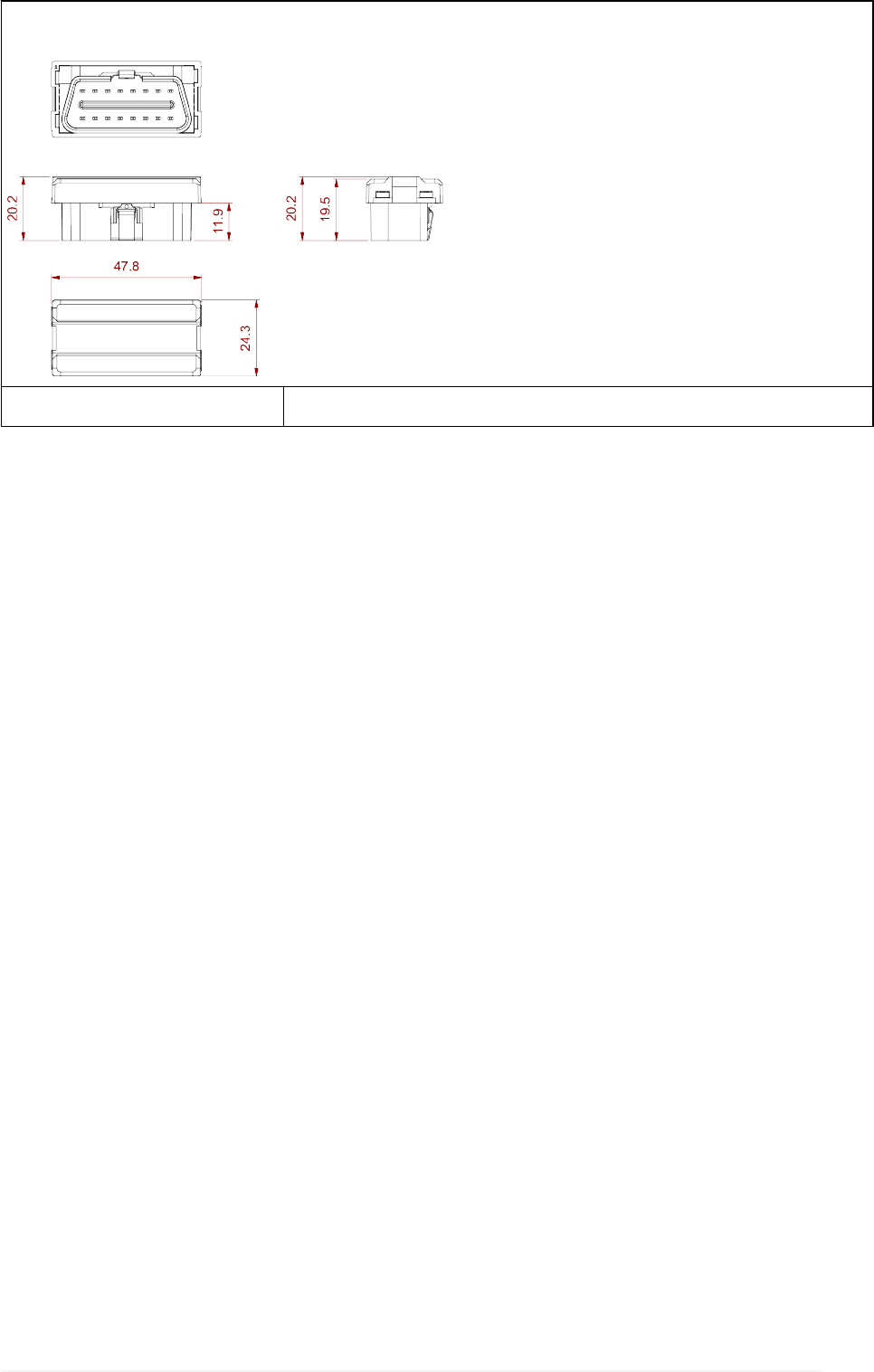
Dimensions in [mm]
Weight 15 g
28

17 ENVIRONMENTAL INFORMATION (For the European
Union)
This product may contain substances that can be hazardous to the environment
or to human health if it is not disposed of properly.
We therefore provide you with the following information to prevent releases of
these substances and to improve the use of natural resources.
Electrical and electronic equipments should never be disposed of in the usual
municipal waste but must be separately collected for their proper treatment.
The crossed-out bin symbol, placed on the product and in this page, remind you
of the need to dispose of properly the product at the end of its life.
In this way it is possible to prevent that a not specific treatment of the substances
contained in these products, or their improper use, or improper use of their parts
may be hazardous to the environment or to human health. Furthermore this
helps to recover, recycle and reuse many of the materials used in these
products.
For this purpose the electrical and electronic equipment producers and
distributors set up proper collection and treatment systems for these products.
At the end of life your product contact your distributor to have information on
the collection arrangements.
When buying this new product your distributor will also inform you of the
possibility to return free of charge another end of life equipment as long as it is
of equivalent type and has fulfilled the same functions as the supplied
equipment.
A disposal of the product different from what described above will be liable to
the penalties prescribed by the national provisions in the country where the
product is disposed of.
We also recommend you to adopt more measures for environment protection:
recycling of the internal and external packaging of the product and disposing
properly used batteries (if contained in the product).
With your help it is possible to reduce the amount of natural resources used to
produce electrical and electronic equipments, to minimize the use of landfills for
the disposal of the products and to improve the quality of life by preventing that
potentially hazardous substances are released in the environment.
29
en