Texa S p A ET17 VEHICLE DIAGNOSTIC SYSTEM User Manual
Texa S.p.A. VEHICLE DIAGNOSTIC SYSTEM
User Manual
TEXA eTRUCK
MANUALE TECNICO
TECHNICAL MANUAL
MANUEL TECHNIQUE
TECHNISCHE BEDIENUNGSANLEITUNG
MANUAL TECNICO
MANUAL TECNICO
INSTRUKCJA OBSŁUGI TECHNICZNEJ
ТЕХНИЧЕСКОЕ РУКОВОДСТВО
Rev.01

2

SUMMARY
REVISION OF THE MANUAL..................................................................5
INTRODUCTION......................................................................................6
1 LEGEND OF THE SYMBOLS USED..................................................7
2 GLOSSARY........................................................................................8
3 GENERAL SAFETY REGULATIONS.................................................9
3.1 Glossary.................................................................................................9
3.2 Operator Safety Regulations..................................................................9
3.2.1 General Safety Regulations........................................................................9
3.2.2 Risk of Asphyxiation...................................................................................9
3.2.3 Risk of Impact and Crushing.......................................................................9
3.2.4 Hazards Caused by Moving Parts............................................................10
3.2.5 Risk of Burning or Scalding......................................................................10
3.2.6 Fire and Explosion Hazard.......................................................................11
3.2.7 Noise Hazard............................................................................................11
3.2.8 High Voltage Hazard.................................................................................11
3.2.9 Poisoning Hazard.....................................................................................12
3.3 General User and Maintenance Warnings...........................................12
4 SPECIFIC USER SAFETY RULES FOR TEXA eTRUCK................13
4.1 General Rules......................................................................................13
4.2 User Safety...........................................................................................13
4.3 Vehicle Safety......................................................................................13
4.4 Device Safety.......................................................................................14
5 ENVIRONMENTAL INFORMATION.................................................16
6 OPERATION OF THE RADIO DEVICES..........................................17
7 REGULATORY INFORMATION.......................................................18
8 TEXA eTRUCK.................................................................................19
9 DESCRIPTION..................................................................................20
10 TECHNICAL FEATURES ...............................................................21
11 INSTALLATION AND CONFIGURATION.......................................23
11.1 Preliminary operations........................................................................23
3
en

11.2 Configuration through the App...........................................................23
11.3 Installation in the Vehicle....................................................................24
11.3.1 Installation through 9-pin Deutsch Adapter.............................................24
12 eTRUCK INSTALLATION KIT FOR VOLVO EURO IV-V
(ACCESSORY)......................................................................................26
13 USE.................................................................................................32
14 POWER SUPPLY ..........................................................................32
15 BLINK CODES................................................................................33
16 MAINTENANCE..............................................................................34
17 TROUBLESHOOTING....................................................................35
18 LEGAL NOTICES............................................................................36
4

TEXA ETRUCK TECHNICAL MANUAL
REVISION OF THE MANUAL
This document is revision 01 of the TEXA eTRUCK technical manual.
Issue date: 11/10/2017
5
en

INTRODUCTION
Dear Customer,
We would like to thank you for choosing a TEXA product for your workshop.
We are certain that you will get the greatest satisfaction from it and receive a
great deal of help in your work.
Please read through the instructions in this manual carefully and keep it for
future reference.
Reading and understanding the following manual will help you to avoid damage
or personal injury caused by improper use of the product to which it refers.
TEXA S.p.A reserves the right to make any changes deemed necessary to
improve the manual for any technical or marketing requirement; the company
may do so at any time without prior notice.
This product is intended for use by technicians specialised in the automotive
field only. Reading and understanding the information in this manual cannot
replace adequate specialised training in this field.
The sole purpose of the manual is to illustrate the operation of the product sold.
It is not intended to offer technical training of any kind and technicians will
therefore carry out any interventions under their own responsibility and will be
accountable for any damage or personal injury caused by negligence,
carelessness, or inexperience, regardless of the fact that a TEXA S.p.A. tool
has been used based on the information within this manual.
Any additions to this manual, useful in describing the new versions of the
program and the new functions associated to it, may be sent to you through our
TEXA technical bulletin service.
This manual is to be considered an essential part of the product it refers to. If it
is resold, the original buyer is therefore required to forward the manual to the
new owner.
Reproduction, whole or in part, of this manual in any form without written
authorisation by the manufacturer is strictly forbidden.
The original manual was written in Italian, every other language is a translation
of the original manual.
© copyright and database rights 2018. The material contained in this
document is protected by copyright and database rights. All rights reserved by
Law and under International Conventions.
6

1 LEGEND OF THE SYMBOLS USED
The symbols used in the manual are described in this chapter.
Asphyxiation Risk
Explosion Risk
High Voltage Hazard
Fire / Burn risk
Poisoning Hazard
Corrosive Substances Risk
Noise Hazard
Moving Parts Risk
Crushing Risk
General Risk
Important information
7
en

2 GLOSSARY
This chapter provides the meaning of the technical terms used in the manual:
•Device: any TEXA eTRUCK device.
•WORKSHOP: the workshop that sells and installs TEXA eTRUCK devices.
•FLEET MANAGER: the manager of the vehicle fleet who subscribed the Fleet
Contract in order to use the services associated with TEXA eTRUCK.
•DRIVER: the driver of a vehicle of the fleet.
•Fleet: the group of vehicles managed by the FLEET MANAGER, where TEXA
eTRUCK is installed.
•TEXA eTRUCK FLEET MANAGER WEB Portal: the WEB portal owned by
TEXA through which the FLEET MANAGER can view the data related to the
vehicles of her/his fleet.
•TEXA eTRUCK WORKSHOP WEB Portal: the WEB portal owned by TEXA
through which the WORKSHOP can view the data related to the vehicles of its
customers.
•Coverage list: the official document that indicates only the vehicles on which you
can safely install the device.
•16-pin OBD socket: the diagnostic socket specific for European EURO 4, EURO
5, EURO 6 vehicles, some American heavy duty vehicles and for light commercial
vehicles.
•9-pin Deutsch OBD socket: the diagnostic socket specific for American heavy
duty vehicles.
•Pairing: the mutual recognition process that takes place when two Bluetooth
devices must establish communication for the first time. It could require you to
enter an identification code (PIN).
8

3 GENERAL SAFETY REGULATIONS
3.1 Glossary
•Operator: qualified individual, in charge of using the device / tool.
•Equipment / device / tool: the purchased product.
•Workplace: the place where the operator must carry out her/his work.
3.2 Operator Safety Regulations
3.2.1 General Safety Regulations
•The operator must be completely clear-headed and sober when using the device;
taking drugs or alcohol before or when operating the device is strictly forbidden.
•The operator must not smoke during device operation.
•The operator must carefully read all the information and instructions in the
technical documents provided with the device.
•The operator must follow all the instructions provided in the technical documents.
•The operator must always watch over the device during the various operating
phases.
•The operator must make sure she/he is working in an environment which is
suitable for the operations that must be carried out.
•The operator must report any faults or potentially hazardous situation in
connection with the workplace or the device.
•The operator must carefully follow the safety regulations required for the
workplace in which she/he is working and required by the operations she/he has
been asked to carry out.
3.2.2 Risk of Asphyxiation
Exhaust gases from internal combustion engines, whether petrol or
diesel, are hazardous to your health and can cause serious harm to
your body.
Safety Precautions:
•The workplace must be equipped with an appropriate ventilation and air extraction
system and must be in compliance with standards according to current national
laws.
•Always activate the air extraction system when working in closed environments.
3.2.3 Risk of Impact and Crushing
The vehicles which are undergoing A/C system recharging operations
and the devices must be properly blocked using the specific
mechanical brakes/blocks while being serviced.
9
en
Safety Precautions:
•Always make sure that the vehicle is in neutral gear (or that it is set in parking
position in case of a vehicle equipped with automatic transmission).
•Always activate the hand brake or parking brake on the vehicle.
•Always block the wheels on the vehicle with the specific mechanical blocks.
•Make sure the device is stable, on a flat surface and that the wheels are locked
with the specific mechanical blocks.
3.2.4 Hazards Caused by Moving Parts
Vehicle engines include parts that move, both while running and not
running (e.g.: the cooling fan is controlled by a thermal switch in
connection with the coolant temperature and can be activated even
when the vehicle is off), that can injure the operator.
Safety Precautions:
•Keep hands away from moving parts.
•Disconnect the engine cooling fan each time the engine you are working on is
still hot. This will avoid the fan from becoming activated unexpectedly even when
the engine is off.
•Do not wear ties, loose clothes, wrist jewellery or watches when working on a
vehicle.
•Keep connection cables, probes and similar devices away from the moving parts
of the engine.
3.2.5 Risk of Burning or Scalding
The parts that are exposed to high temperatures in engines that are
moving or have just stopped could burn the operator.
Remember that catalytic mufflers reach very high temperatures, able
to cause serious burns or even start fires.
Acid in the vehicle batteries is another potential hazard.
Safety Precautions:
•Protect your face, hands, and feet by using suitable protection.
•Avoid contact with hot surfaces, such as spark plugs, exhaust pipes, radiators
and connections within the cooling system.
•Make sure there are no oil stains, rags, paper or other inflammable material near
the muffler.
•Avoid splashing electrolyte onto your skin, eyes and clothes, as it is a corrosive
and highly toxic compound.
10
3.2.6 Fire and Explosion Hazard
The following are potential fires and / or explosion hazards:
•The types of fuel used by the vehicle and the vapours released by these
fuels.
•The refrigerants used by the A/C system.
•The acid in the vehicle batteries.
Safety Precautions:
•Let the engine cool down.
•Do NOT smoke near the vehicle.
•Do NOT expose the vehicle to open flames.
•Make sure that the electrical connections are all well insulated.
•Collect any fuel that might have spilled.
•Collect any refrigerant that might have spilled.
•Make sure you are always working in an environment equipped with a good
ventilation and air extraction system.
•Always activate the air extraction system when working in closed environments.
•Cover the openings of the batteries with a wet cloth in order to stifle the explosive
gases before proceeding in testing or recharging.
•Avoid causing sparks when connecting cables to the battery.
3.2.7 Noise Hazard
Loud noises that may occur within the workplace, especially during
service operations, may damage the operator's hearing.
Safety Precautions:
•Protect your ears with suitable protective ear wear.
3.2.8 High Voltage Hazard
The voltage supply from the mains that powers the devices in the
workplace and the voltage within the vehicle starter system is a
potential shock hazard to the operator.
Safety Precautions:
•Make sure the electrical system in the workplace is compliant to current national
standards.
•Make sure the device being used is connected to ground.
•Cut off the power supply voltage before connecting or disconnecting cables.
•Do NOT touch the high voltage cables when the engine is on.
11
en

•Operate in conditions of insulation from ground.
•Work with dry hands only.
•Keep conductive liquids away from the engine while working.
•Never leave tools on the battery in order to avoid accidental contacts.
3.2.9 Poisoning Hazard
The hoses used to extract the gases can release toxic gases,
dangerous to the operator if exposed to temperatures higher than 250
°C or in case of a fire.
Safety Precautions:
•Should you inhale these gases, seek medical advice immediately.
•Use neoprene or PVC gloves when eliminating combustion deposits.
3.3 General User and Maintenance Warnings
When using the device or carrying out ordinary maintenance (e.g. fuse
replacement) on the device, carefully follow the information provided below.
•Do not remove or damage the labels/tags and the warnings on the device; do
NOT in any case make them illegible.
•Do not remove, or block, any safety devices the device is equipped with.
•Only use original spare parts or spare parts approved by the manufacturer.
•Contact your retailer for any extraordinary maintenance.
•Periodically check the electrical connections of the device, making sure they are
in good condition and replacing any damaged cables.
•Periodically check parts that are subject to wear and replace them if necessary.
•Do not open or disassemble the device.
12
4 SPECIFIC USER SAFETY RULES FOR TEXA eTRUCK
The technology used for the design and manufacturing control of TEXA
eTRUCK makes it a reliable, simple and safe device to use.
Users of TEXA eTRUCK are required to follow the general safety rules, to use
the device for its intended use only and to take care of it as indicated in this
manual.
4.1 General Rules
•The user must have carefully read all the information and instructions indicated
in the technical documents provided with the device.
4.2 User Safety
The device was designed and created in order to allow an easy, fast
and safe installation; nevertheless, it is impossible to completely
eliminate some of the risks connected to this operation.
Safety Measures:
•Make sure the vehicle's instrument panel is off before starting the installation.
•Make sure the vehicle on which you wish to install the device is on a flat surface
and with the parking brake engaged.
•Make sure there are not any damaged cables around the diagnostic socket.
•Be careful not to injure yourself on sharp plastic edges or metal plates around the
diagnostic socket.
The position in which the device is placed and the behaviour of its LEDs
were designed to avoid any possible obstacle or interference for the
driver.
Lack of concentration while driving puts both the driver and the vehicle
in danger.
Safety Measures:
•Do not drive the vehicle before reassembling the plastic parts and panels
previously removed.
•Do not get distracted by checking the status of the device or interacting with it
neither directly or through the display unit.
4.3 Vehicle Safety
The device was designed and created in order to allow an easy, fast
and safe installation; nevertheless, it is best to be sure not to
compromise any vehicle function during this operation.
13
en
Safety Measures:
•Delicately remove any plastic part, cover or bulkhead that might cover the
diagnostic socket, being careful not to loose any screw or fastening hook.
•Be careful not to damage or disconnect any plastic part or cable near the
diagnostic cable.
•Carefully reposition and close any plastic part, cover or bulkhead once the
device's installation and configuration phase is completed.
•Do not install the device on vehicles that are not supported.
4.4 Device Safety
The device was designed to be used in specific environmental
conditions.
Using the device in environments with temperatures and humidity that
differ from those specified may impair its efficiency.
Safety measures:
•Always place the device in a dry area.
•Do not expose or use the device close to heat sources.
•Position the device in order to guarantee its proper ventilation.
•Do not use corrosive chemicals, solvents or harsh detergents to clean the device.
The device was created to be mechanically resistant and suitable for
the use it was designed for.
Careless use and excessive mechanical strain may impair its
efficiency.
Safety measures:
•Do not drop, shake or knock the device.
•Do not carry out any type of intervention that may damage the device.
•Do not open or disassemble the device.
•Do not force the device or the connectors and take the utmost care during all
connecting and disconnecting operations.
•Connect the device properly and securely in order to avoid it from accidentally
disconnecting during use.
•Do not use screwdrivers or other tools to lever and disconnect the device.
The device was manufactured to be electrically safe and to work with
specific supply voltage levels.
Failure to comply with the specifications related to the power supply
may impair the device's efficiency.
14

Safety measures:
•Do not wet the device with water or other liquids.
•Use the device on vehicles with a 12-24 V DC power supply, chassis connected
to the negative pole, and in any case only on supported vehicles.
•The connection for the device's power supply must always be with the battery-
operated system of the vehicle being tested.
The electromagnetic compatibility tests carried out on the device
guarantee that it can be adapted to the technologies normally used on
vehicles (ex.: engine control, ABS, airbag, etc.). Nevertheless, if
malfunctions occur, contact the vehicle's dealer.
15
en

5 ENVIRONMENTAL INFORMATION
For information regarding the disposal of this product please see
the pamphlet supplied.
16

6 OPERATION OF THE RADIO DEVICES
Wireless connection with Bluetooth® technology
The wireless connection with Bluetooth technology is a technology that supplies
a standard and reliable method to exchange information between different
devices, using radio waves. Products such as cellular phones, portable devices,
computers, printers, cameras, pocket PCs etc. use this type of technology.
The Bluetooth interface searches for compatible electronic devices according
to the radio signal they generate and establishes a connection between them.
The tools operate a selection suggesting only compatible / enabled devices.
This does not exclude the presence of other sources of communication or
interference.
THE EFFICIENCY AND THE QUALITY OF THE BLUETOOTH
COMMUNICATION MAY BE INFLUENCED BY THE PRESENCE OF RADIO
DISTURBANCE SOURCES. THE COMMUNICATION PROTOCOL HAS
BEEN DEVELOPED TO MANAGE THESE TYPES OF ERRORS; HOWEVER,
IN THESE CASES COMMUNICATION MAY BECOME DIFFICULT AND
CONNECTION MAY REQUIRE SEVERAL ATTEMPTS.
SHOULD THE WIRELESS CONNECTION ENCOUNTER SERIOUS
PROBLEMS THAT MAY COMPROMISE A REGULAR COMMUNICATION,
THE SOURCE OF THE ENVIRONMENTAL ELECTROMAGNETIC
INTERFERENCE MUST BE IDENTIFIED AND ITS INTENSITY REDUCED.
Position the product in order to guarantee the correct operation of its radio
devices. In particular, do not cover it with any shielding or metal materials in
general.
17
en
7 REGULATORY INFORMATION
Simplified EU Declaration of Conformity
The manufacturer, TEXA S.p.A, declares that the type of radio
equipment TEXA eTRUCK is compliant with the RED 2014/53/EU
directive.
The complete text of the EU declaration of conformity is available at
the following Internet address http://www.texa.it/download.
18
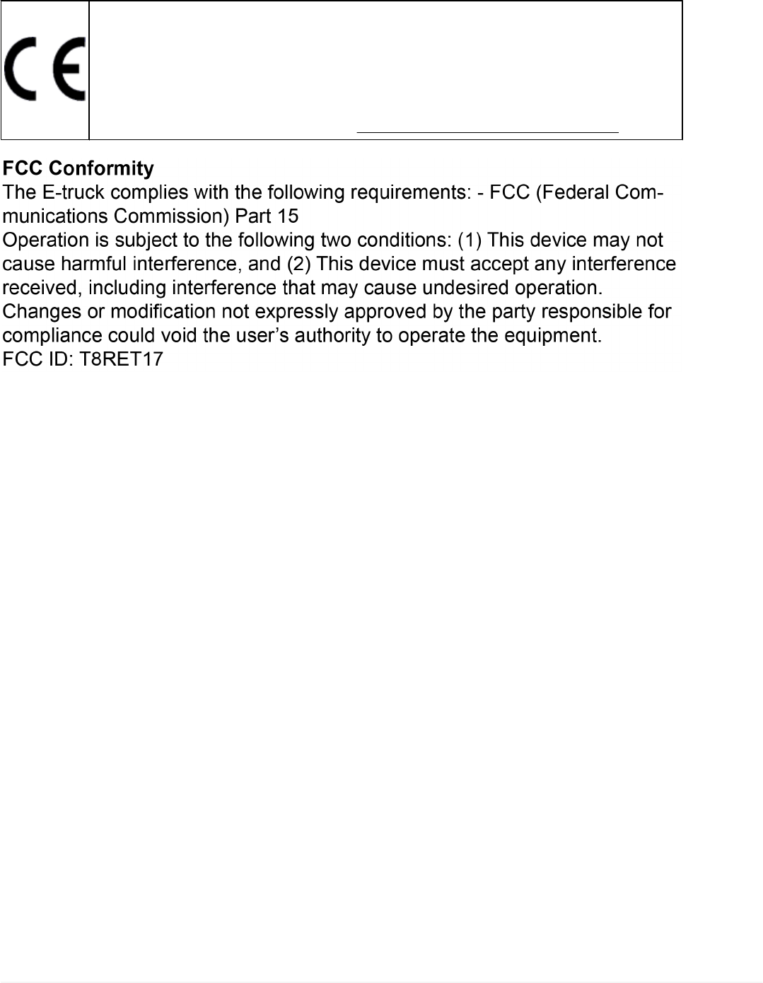
8 TEXA eTRUCK
TEXA eTRUCK is a compact device that allows the workshop to constantly
monitor the vehicle status remotely, managing its maintenance from a predictive
point of view and carrying out adjustment functions that allow restoring the
optimal vehicle conditions.
For the WORKSHOP: eTRUCK is the linking element between the mechanic
and the industrial vehicle, fostering customer loyalty through a continuous
assistance service.
For the DRIVER and FLEET MANAGER: eTRUCK is the ideal solution for
DRIVERS and FLEET MANAGERS who want to be constantly updated on the
conditions of their vehicles, as it allows them to realise specific actions for cost
reduction and vehicle use optimisation, thanks to a dedicated app and
management portal.
The device is able to acquire the required data from the vehicle and to transmit
it in real time via Bluetooth to the smartphone selected as a display unit.
For this to occur, a specific app must be installed in the smartphone.
The app can be downloaded directly from the Internet through
and .
Furthermore, because of its small size, the device takes up little space and does
not interfere with driving.
19
en
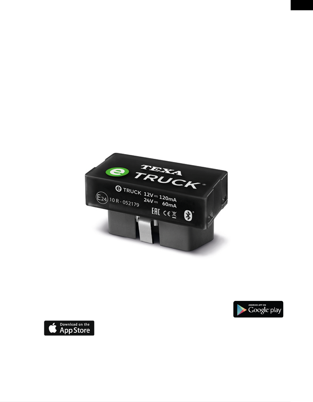
9 DESCRIPTION
1. LED
•Red / green LED
•Blue LED
2. OBD connector
3. Retention hook
(*) For further information see the Blink Codes chapter.
20

10 TECHNICAL FEATURES
Manufacturer TEXA S.p.A.
Model TEXA eTRUCK
Processor ARM Cortex M4 (STM32F439ZIY6)
Memory •SDRAM: 8 MB
•Flash NAND: 4 GB
Communication •Bluetooth Classic (2.1)
•Bluetooth 4.0 Low Energy (Smart Ready)
Diagnostic connector OBD socket ISO15031-03 for 24 V systems
Supported
automotive bus types
•4 HS CAN transceivers connected to OBD pins 3-11,
1-9, 12-13, 6-14 that can be enabled individually
•1 J1708 transceiver connected to pins 12-13
•1 ISO9141-2, ISO14230 transceiver with 60mA
current protection connected to pins 3 or 7
Visual warnings •1 green/red bi-coloured LED
•1 blue LED
Inertial sensor •Accelerometer: 3 axis, ± 16 G F.S.
•Gyroscope: 3 axis, ± 2000 DPS G F.S.
Supply voltage 12 / 24 Vdc
Consumptions •Normal mode: 60 / 120 mA (12 / 24 Vdc)
•Standby: < 6 mA
Device activation Possible from OBD pins 1 and 8 or by monitoring the
battery voltage
Operating
temperature - 20 °C – 60 °C
Storage temperature - 40 °C – 85 °C
ISM operating
frequency band 2400 - 2483.5 MHz
Maximum transmit
power in frequency
band
4 dBm
Relative humidity 10% – 80% without condensation
21
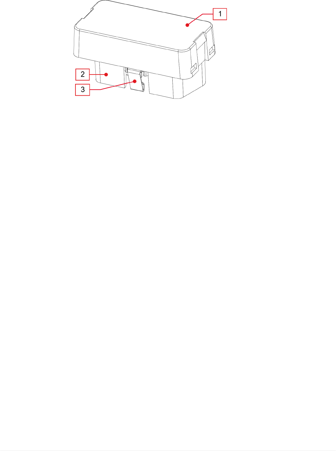
en
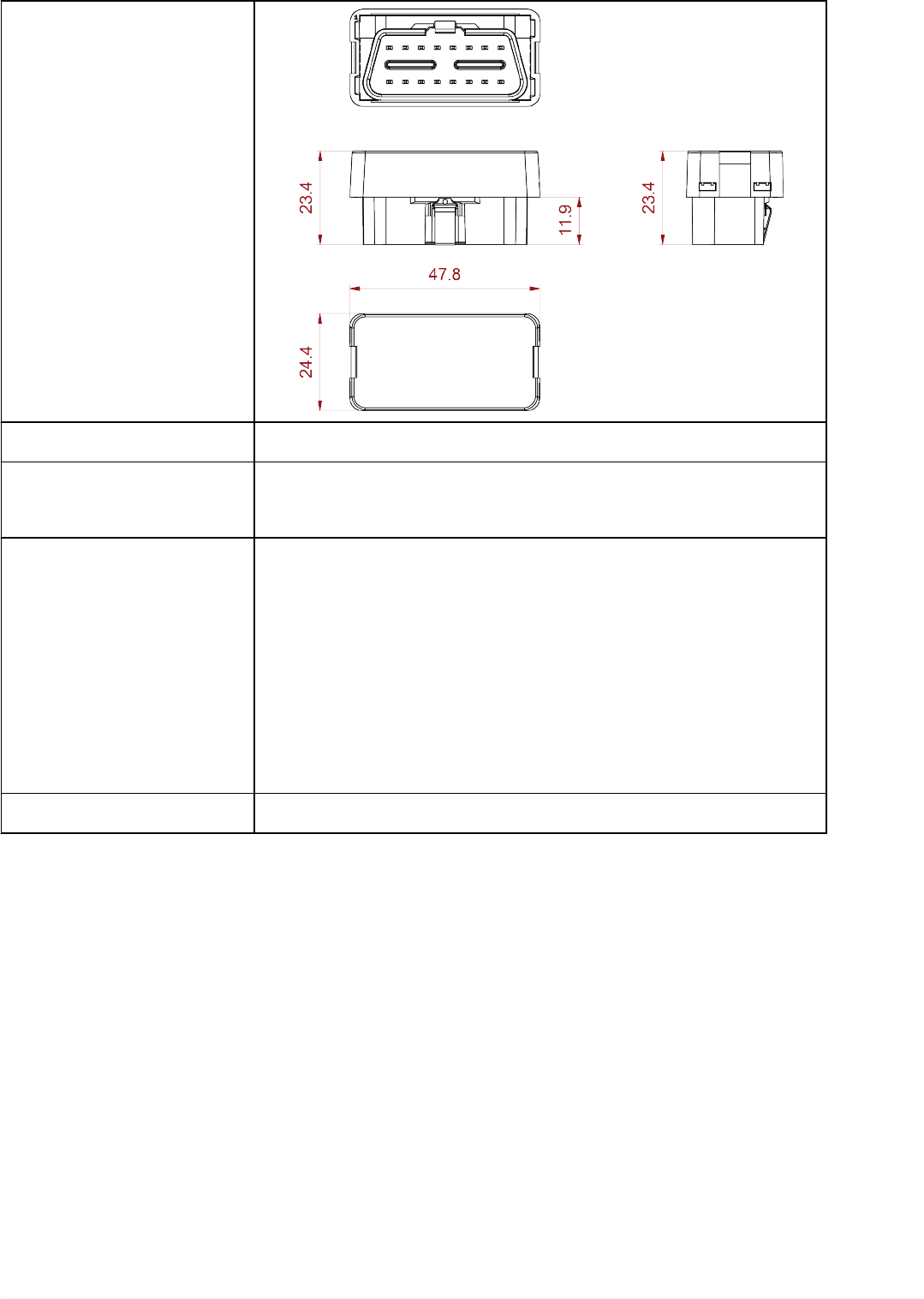
Dimensions in [mm]
Weight 15 g
Directives RED 2014 / 53 / EU
ROHS 2011 / 65 / EU
Product standards
EN 301 489-1 V2.1.1
EN 301 489-17 3.1.1
EN 300 328 V2.1.1
EN 62311:2008
EN 60950-1:2006 / A11+A1+A12+AC:2001+A2:2013
ISO 7637-1:2002
ISO 7637-2:2011
Regulations UN / ECE R10
22

11 INSTALLATION AND CONFIGURATION
The following chapters illustrate how to install and configure a device or a series
of devices in sequence.
At the end of the installation and configuration procedures, the device is able to
work only on the vehicle on which it is installed.
Do not install the device on vehicles that do not meet the
compatibility requirements established by TEXA S.p.A.
Do not move the device onto any other vehicle without performing
the installation and configuration procedure.
11.1 Preliminary operations
•Sign up on the eTRUCK WORKSHOP Web Portal
•Get the FLEET MANAGER email address
•Download the WORKSHOP app from Google Play Store or Apple App Store
•Keep the devices to be installed at hand
11.2 Configuration through the App
The following procedure must be performed respecting the times and requests
of the device installation app.
Proceed as follows:
1. Launch the WORKSHOP app.
2. Enter the FLEET MANAGER email address.
3. Identify the device with one of the following modes:
•Scan the QR Code on the device to get its serial number, wait for the app to get
the PIN code via the Internet (default and recommended mode)
•Manually enter the serial number indicated on the device, wait for the app to get
the PIN code via the Internet (use this mode if scanning the QR Code is not
possible)
•Manually enter the serial number and PIN code indicated on the device (use this
mode if no Internet connection is available)
4. Enter the vehicle's license plate number when requested to by the app.
5. Select the Make and Model using the specific drop-down menus.
6. Connect the device to the vehicle as explained in the section Installation in
the Vehicle.
7. Launch the Bluetooth configuration.
The configuration procedure is complete.
23
en
The app gives the possibility to install other devices in sequence or finish the
installations.
11.3 Installation in the Vehicle
A screwdriver may be needed to loosen the screws that fasten the
panels that cover the diagnostic socket.
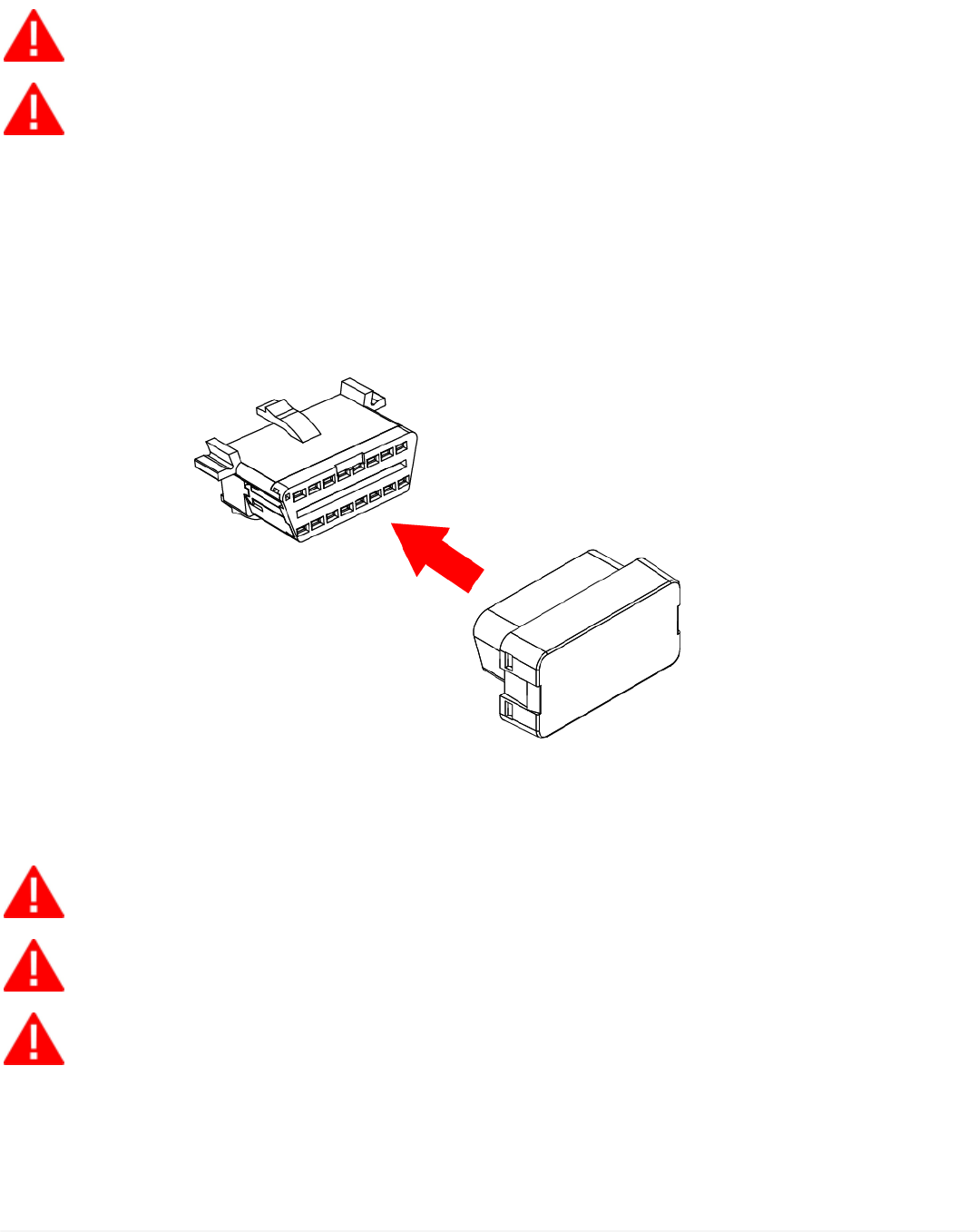
Make sure the device is securely connected to the diagnostic
socket to avoid it from accidentally disconnecting during use.
Proceed as follows:
1. Turn off the vehicle (instrument panel off).
2. Locate the diagnostic socket.
3. Carefully remove any panel covering the diagnostic socket.
4. Connect the device to the diagnostic socket.
5. Turn on the vehicle (instrument panel on).
6. Carefully reposition any removed panel.
Make sure that the various components around the diagnostic
socket do not damage the device during installation.
Make sure that the position of the device does not interfere with
driving.
Do not start driving before the plastic parts and panels removed are
repositioned correctly.
11.3.1 Installation through 9-pin Deutsch Adapter
The device can also be installed on vehicles with a 9-pin Deutsch socket through
the specific adapter supplied by TEXA S.p.A. (code: 3907794).
24

For this installation mode, all the warnings in the previous section apply.
Proceed as follows:
1. Turn off the vehicle (instrument panel off).
2. Locate the diagnostic socket.
3. Carefully remove any panel covering the diagnostic socket.
4. Connect the device to the adapter.
5. Connect the adapter to the diagnostic socket.
6. If necessary, fasten the adapter to the dashboard using screws, in order not
to compromise driving.
7. Turn on the vehicle (instrument panel on).
8. Carefully reposition any removed panel.
25
en

12 eTRUCK INSTALLATION KIT FOR VOLVO EURO IV-V
(ACCESSORY)
The industrial vehicles of the Swedish manufacturer Volvo Truck, with approval
class Euro IV and Euro V, were created in different configurations, many of
which have two diagnostic sockets.
One is the EOBD connection, the other is the Volvo Truck proprietary diagnostic
socket (Texa ref.: connection cable 3151 / T11B).
In order to use the eTRUCK device to its fullest potential, the electrical wiring
needs to be modified in this series of vehicles.
This is because the installed EOBD diagnostic socket does not allow analysing
all the values, but only the parameters of the EOBD standard protocol.
The modification does not require special technical skills, and the installation
kit contains the material and information that are needed to carry out the
modification.
However, the work should be performed by technical personnel with all the
necessary knowledge to perform it properly.
Following is a step-by-step description of the procedure operations,
accompanied by explanatory images.
NOTES:
This technical information sheet is ONLY for the vehicles with the two diagnostic
sockets.
The vehicles with only the EOBD socket are already 100% compatible with the
eTRUCK device.
26
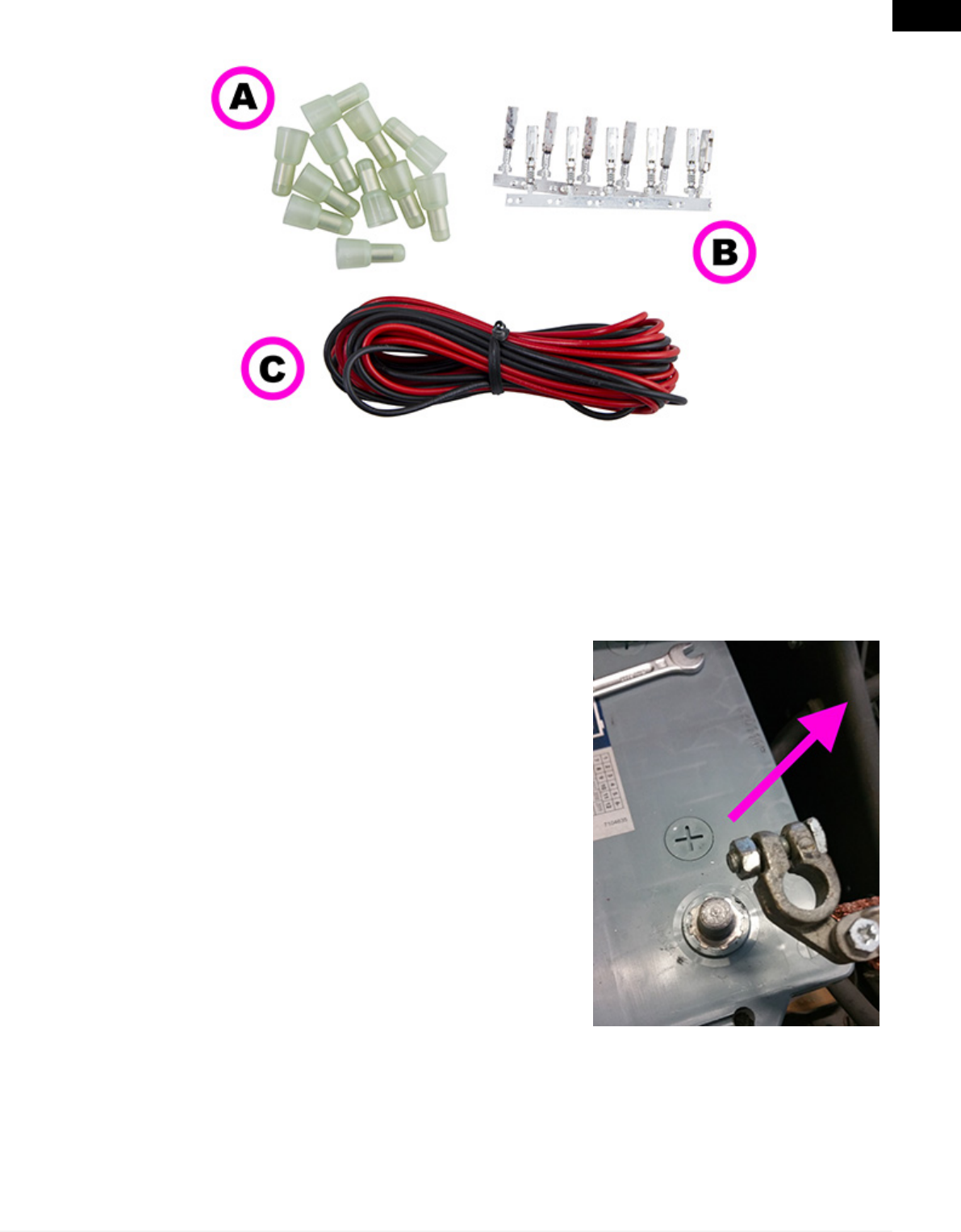
The installation kit includes:
A. Cable joints
B. Cable terminals
C. Electrical cables
To install the kit properly and access all TEXA eTRUCK functions, carefully
follow the instructions below.
1. Make sure the parking brake is engaged.
2. Disconnect the batteries.
3. Locate the diagnostic sockets.
27
en

4. Remove the 3 screws and the plastic nut.
5. Remove the heating air duct.
D. EOBD socket
E. Volvo Truck proprietary
socket
F. Fastening screws and
nuts
6. Remove both the yellow diagnostic socket and
the EOBD socket from their housings, acting on
the fasteners.
7. Make sure the EOBD diagnostic socket pin 16
(black wire of the original wiring) is powered by a
direct battery positive (+30) and not a key-on
(+15).
If necessary, restore the EOBD socket wiring.
Otherwise, full functionality of TEXA eTRUCK
is not guaranteed.
D. EOBD socket
E. Volvo Truck proprietary
socket
28
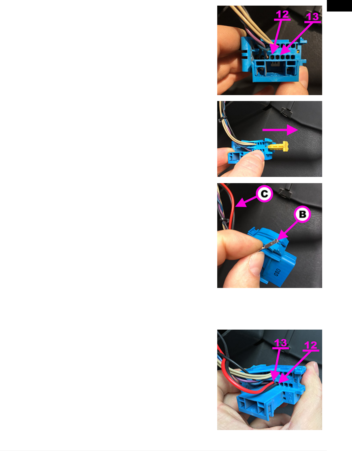
8. On the EOBD socket (light blue connector),
locate pins 12 and 13 (with no cables installed).
9. Remove the yellow fastener from the EOBD
socket.
10. Using the supplied red/black cables and
terminals, crimp the terminals on the wires.
B. Cable terminals
C. Electrical cables
11. Insert the black cable into pin 12 and the red
cable into pin 13 of the EOBD socket.
Cable colour: black - Pin: 12
Cable colour: red - Pin: 13
29
en
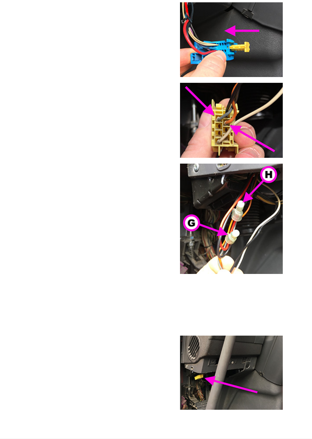
12. Reinsert the yellow fastener.
13. Fasten the two red and black cables together
with the existing wiring, following it up to the
yellow diagnostic socket.
14. On the Volvo Truck proprietary socket (yellow
connector), locate pins 2 (grey cable) and 3
(orange cable).
15. Using the supplied cable joints, connect the
black wire to the grey wire and the red wire to the
orange wire of the yellow diagnostic socket.
WARNING: to be able to use the cable joint,
you need to cut the grey and orange wires.
Cable matching:
•Black + grey
•Red + orange G. Cable joint with black and
grey wires
H. Cable joint with red and
orange wires
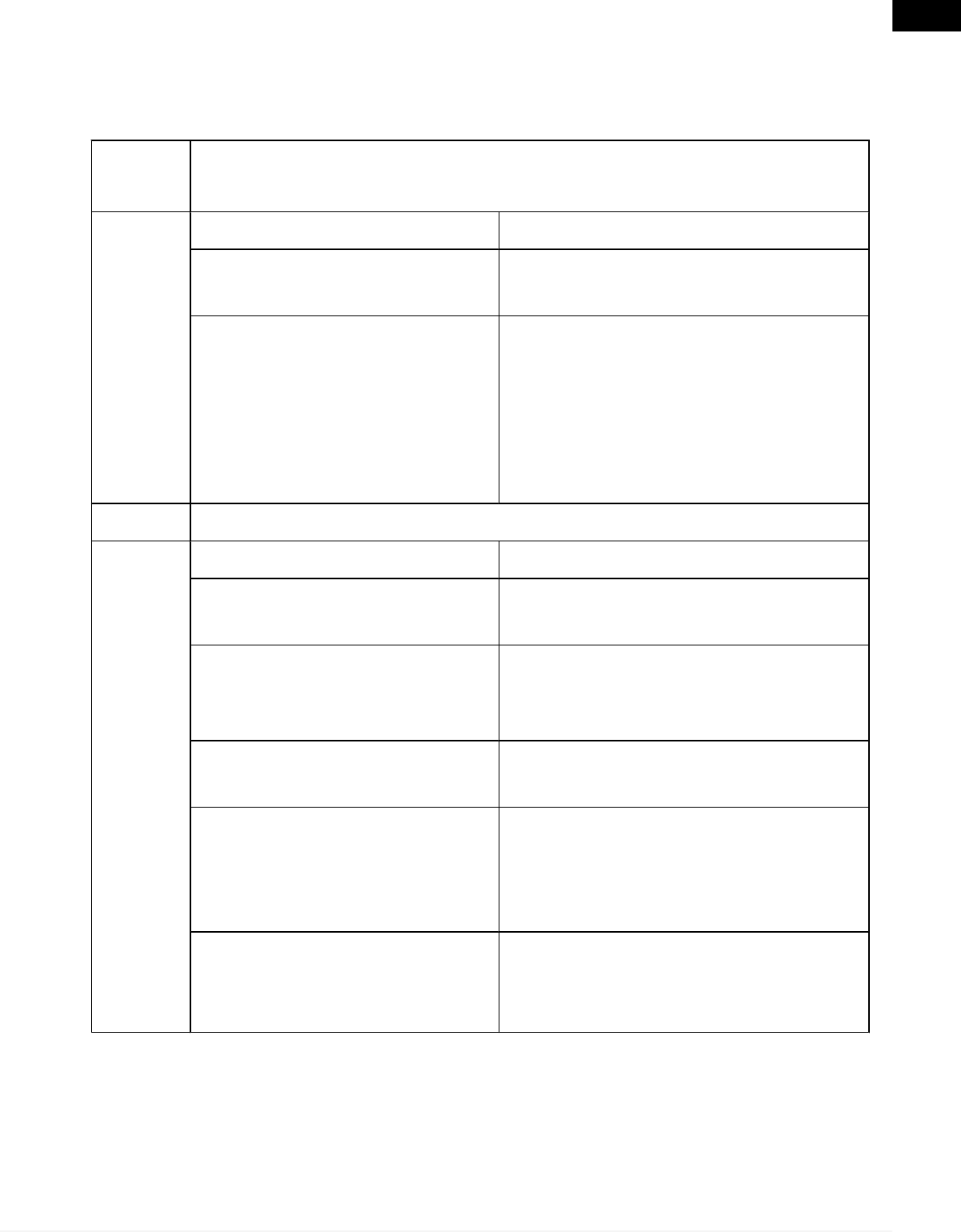
16. Install the yellow diagnostic socket back onto
its bracket.
30
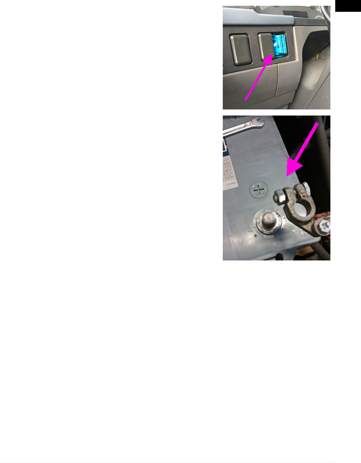
17. Install the EOBD socket back onto its bracket.
21. Reconnect the batteries
22. TEXA eTRUCK can now be installed in the
EOBD socket and used at its fullest potential.
31
en

13 USE
No further action must be carried out after installing and configuring the device.
Any interaction occurs through the smartphone.
The device activates as soon as the vehicle's instrument panel is turned on and
it connects automatically to the smartphone if it is within the operating range of
the device's Bluetooth antenna.
While driving, do not get distracted to check the status of the device
or to interact with it either directly or through the smartphone.
For further help, contact your Retailer or send a request for assistance
through the function TEXA iSupport - eTRUCK.
14 POWER SUPPLY
The device draws its power supply directly from the battery of the vehicle it is
connected to through the diagnostic socket.
The vehicle's diagnostic socket is always powered, even when the engine and
instrument panel are off.
The absorption never affects the battery's charge, however you should
disconnect the device from the vehicle's diagnostic socket if the vehicle
is not used for a long period of time.
32

15 BLINK CODES
Starting TEXA eTRUCK by plugging it in (inserting TEXA eTRUCK in the
vehicle's diagnostic socket) and with the vehicle stationary.
LED Meaning
GREEN - BLUE: quick
alternate blink
Device connected to the vehicle, available for
pairing.
-Device connected via Bluetooth:
LED Meaning
BLUE: Slow blink Device configured and connected to the vehicle.
BLUE: 2 blinks
The device is in one of the following situations:
•configuration check in progress
•not configured but connected to the vehicle
•not configured and not connected
BLUE: Quick blink Device configured but not connected to the
vehicle.
-Device NOT connected via Bluetooth:
LED Meaning
GREEN: Slow blink Device configured and connected to the vehicle.
GREEN: 2 blinks
The device is in one of the following situations:
•configuration check in progress
•not configured but connected to the vehicle
•not configured and not connected
GREEN: Quick blink Device configured but not connected to the
vehicle.
Starting TEXA eTRUCK by turning on the engine (device already plugged
in) and with the vehicle stationary.
LED Meaning
BLUE: 2 blinks Smartphone authentication successful.
33
en

Every time TEXA eTRUCK is started:
LED Meaning
GREEN: 2 blinks User application successfully started.
RED: 4 blinks Error in starting the user application.
16 MAINTENANCE
This product does not require special maintenance.
For a longer tool life, keep the product clean and follow the instructions detailed
in this manual carefully.
For further help, contact your Retailer or send a request for
assistance through the TEXA iSupport function.
34
17 TROUBLESHOOTING
Contact your supplier / retailer about any technical problem that cannot be
resolved by following the instructions below.
Problem The device is connected to the diagnostic socket.
The red LED blinks 4 times.
Possible Cause Possible Solution
The vehicle is not compatible
with the device.
Use the device only on compatible
vehicles.
There is an error condition.
Carefully disconnect and reconnect
the device.
If the error persists, contact your
Retailer or send a request for
assistance through the function
TEXA iSupport - eTRUCK.
Problem The smartphone does not communicate with the device.
Possible Cause Possible Solution
The vehicle's instrument panel
is off.
Turn on the vehicle's instrument
panel.
The device is not properly
connected and appears as
switched off.
Carefully disconnect and reconnect
the device to the diagnostic socket
making sure it is inserted securely.
The smartphone's Bluetooth is
not active. Activate the smartphone's Bluetooth
The smartphone is not within
the device's Bluetooth
operating range.
Place the smartphone within the
device's operating range, that is
inside the vehicle or in its immediate
surroundings.
Other wireless
communications interfere with
the signal.
Wait and try to communicate again.
If necessary, move the vehicle into
another position.
35
en

18 LEGAL NOTICES
TEXA S.p.A.
Via 1 Maggio, 9 - 31050 Monastier di Treviso - ITALY
Tax Code - Company Register of Treviso ID No. - VAT No.: 02413550266
Single-shareholder company subject to the direction and coordination activities
of Opera Holding S.r.l.
Paid-up share capital 1,000,000 € - R.E.A. (Economic Administrative Index) No.
208102
Legal Representative Bruno Vianello
Phone +39 0422.791.311
Fax +39 0422.791.300
www.texa.com
For information regarding the legal notices, please refer to the International
Warranty Booklet provided with the product.
36