Texas Instruments 1180DB868 The CC1180DB is a development tool for TIs sub 1 GHz CC1180 chip. User Manual CC2530ZNP mini kit quick start guide
Texas Instruments Inc. The CC1180DB is a development tool for TIs sub 1 GHz CC1180 chip. CC2530ZNP mini kit quick start guide
Users Manual
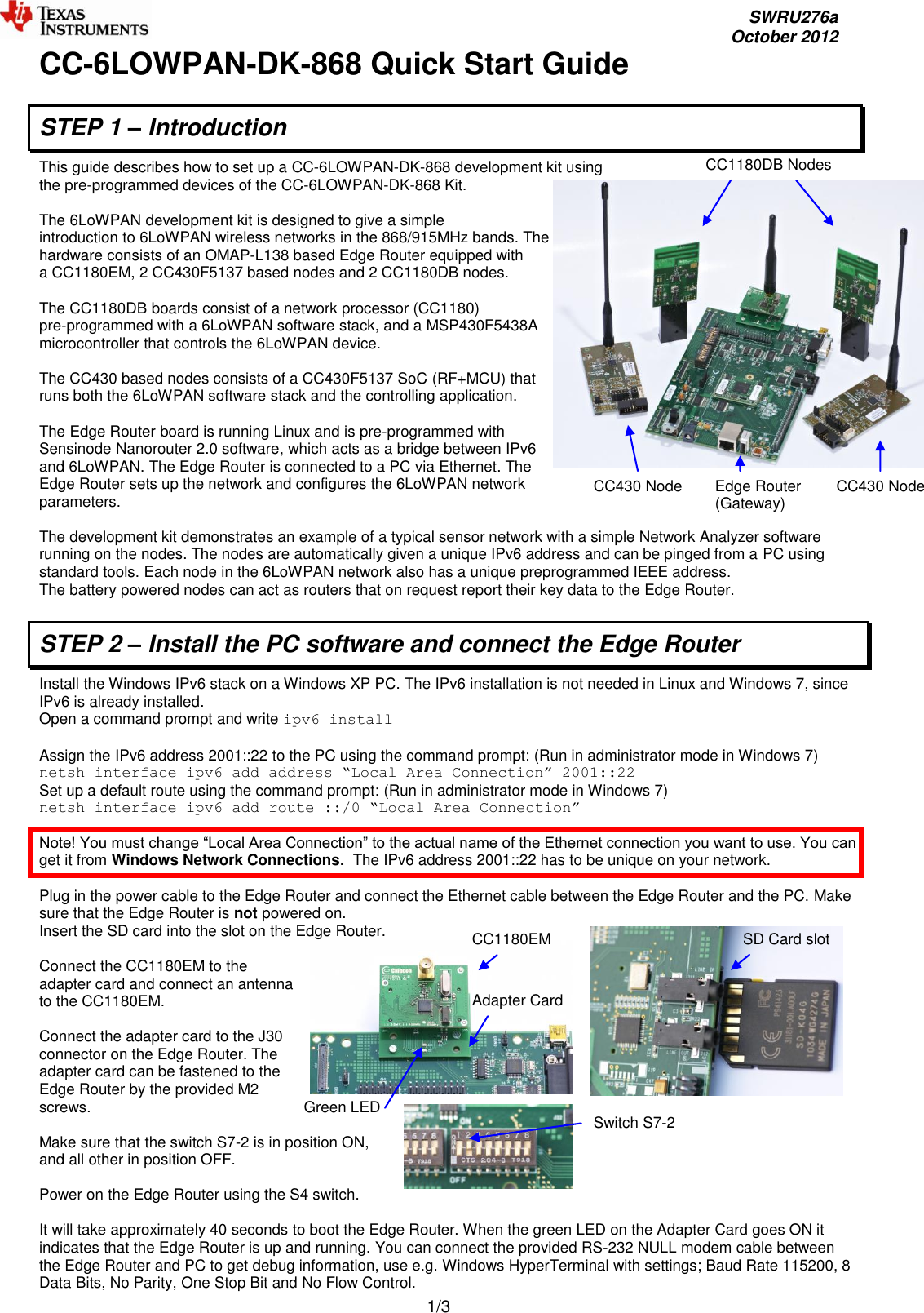
![SWRU276a October 2012 2/3 Jumper J1 STEP 3 – Connecting the nodes to the 6LoWPAN network Insert batteries in one or more of the CC1180DB boards and make sure the jumper is connected between P1-1 and P1-2 to power on the node. It will automatically connect to existing network. LEDs D1 and D2 are controlled from the CC1180 network processor and gives status on node connection. When the CC1180DB node is connected to the network the green LED (D2) will be on, if not connected it will be off. The red LED (D1) blink when node is communicating. LEDs D3 and D4 are controlled from the host MCU and displays the RSSI value. Both LEDs off: RSSI above -40dBm, green LED on red LED off: RSSI between -40 and -65dBm, both LEDs on: RSSI between -65 and -90dBm, green LED off red LED on: RSSI below -90dBm. The red LED toggles with 1 sec interval if 3 concurrent reply messages were missed or Analyzer is not activated on PC. Insert batteries in one or more of the CC430F5137 battery packs and connect an antenna. Connect the battery pack cable to power on the node. LEDs D1 and D2 are controlled from the 6LoWPAN stack in CC430 and gives status on node connection. When the CC430 node is connected to the network the green LED (D1) will be on. The red LED (D2) blink when node is communicating. When nodes are powered on they connect automatically to the 6LoWPAN network, either directly to the Edge Router or via other nodes (Routers) in the network. Upon request from the Edge Router they send messages including network information to the Edge Router. Warning! To minimize risk of personal injury or property damage, never use rechargeable batteries to power the boards. Do not leave the EVM powered when unattended. Note that there should only be one active power source at any one time. STEP 4 – Installing and Using NodeView Network Analyzer software Node View can be used to interact with the nodes in the network. It has several powerful features such as Network Analyzer, message logs, running demo applications and to send custom data to nodes. Download and install the latest Java runtime engine from www.java.com to your Windows PC. Minimum version of Java to run NodeView is 1.6.0 Extract the provided NodeView package to C:\NodeView NodeView package can be found via link on www.ti.com Start NodeView by double-clicking the extracted NodeViewProDyn.jar file in C:\NodeView Connect to your Edge Router by selecting File -> Add NanoRouter IPv6 in the RouterView tab. Enter the IPv6 address of the Edge Router which is 2001::11 The connected Edge Router is then shown in the Routers field. The connected nodes are shown in the Nodes field. You can now use standard network tools to communicate with the nodes. To ping a node right-click a node and copy the IPv6 address of the node. Open a command prompt on your Windows XP PC and write: ping6 –n 10 [IPv6 address] Replace [IPv6 address] with the copied IPv6 address of the node you want to ping. This example will ping the node 10 times. Use the ping command on Linux and Windows 7. You can also view the network topology in the NodeView tab Network analyzer. STEP 5 – Next steps Extensive examples are provided to help you get started. Building and running each example is recommended to become acquainted with the devices. Refer to the examples’ wiki page for more information. For detailed information about the sample applications please see the following resources: CC-6LOWPAN-DK-868 wiki page: http://processors.wiki.ti.com/index.php/CC-6LoWPAN CC-6LOWPAN-DK-868 product web page: http://www.ti.com/6lowpan](https://usermanual.wiki/Texas-Instruments/1180DB868/User-Guide-1909003-Page-2.png)