Texas Instruments 2543EM The CC2543EM is a development tool for TI’s 2.4 GHz CC2543 proprietary System-on-Chip User Manual
Texas Instruments Inc. The CC2543EM is a development tool for TI’s 2.4 GHz CC2543 proprietary System-on-Chip Users Manual
user manual

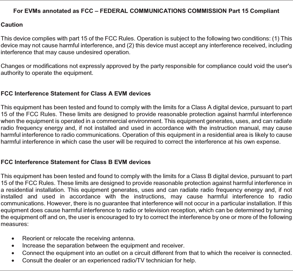
![Important Notice for Users of this Product in Japan This development kit is NOT certified as Confirming to Technical Regulations of Radio Law of Japan! If you use this product in Japan, you are required by Radio Law of Japan to follow the instructions below with respect to this product: (1) Use this product in a shielded room or any other test facility as defined in the notification #173 issued by Ministry of Internal Affairs and Communications on March 28, 2006, based on Sub-section 1.1 of Article 6 of the Ministry’s Rule for Enforcement of Radio Law of Japan, (2) Use this product only after you obtained the license of Test Radio Station as provided in Radio Law of Japan with respect to this product, or (3) Use of this product only after you obtained the Technical Regulations Conformity Certification as provided in Radio Law of Japan with respect to this product. Also, please do not transfer this product, unless you give the same notice above to the transferee. Please note that if you could not follow the instructions above, you will be subject to penalties of Radio Law of Japan. Texas Instruments Japan Limited (address) 24-1, Nishi-Shinjuku 6 chome, Shinjukku-ku, Tokyo, Japanhttp://www.tij.co.jp!"#$%&'()*+, !"#$%&'()*+, !"#$%&'()*+, !"#$%&'()*+, -./0123456789:;<=>)?@ABCD-./0123456789:;<=>)?@ABCD-./0123456789:;<=>)?@ABCD-./0123456789:;<=>)?@ABCD-EF*"#$%GH)3IJKLMN*'OIPQ*RSTU*VW<X()R'YZ[\]&@A^*_"+,ZY`RDabcJKLdefgh6ih1jh1k%6lZmn18o3p28qrstuvh173k_wOxT'JKyz{*|}~_"#$R'YZDac}*<X"#$R'YZDac456789:;<X"#$R'YZD?I-EF3I*"#$%&'()*+,<I%HR@II_R*HA^D <MN>R93IJKL*g]8$`T]&<"¡,ZY`RDq-¢0£¤¥¦§¤¨©ª§¨«¬®q-¢0£¤¥¦§¤¨©ª§¨«¬®q-¢0£¤¥¦§¤¨©ª§¨«¬®q-¢0£¤¥¦§¤¨©ª§¨«¬®¯°±²³´µ²³¶·¸¹ºbk¯°±²³´µ²³¶·¸¹ºbk¯°±²³´µ²³¶·¸¹ºbk¯°±²³´µ²³¶·¸¹ºbkµ²³»¼½©µ²³»¼½©µ²³»¼½©µ²³»¼½©http://www.tij.co.jp](https://usermanual.wiki/Texas-Instruments/2543EM/User-Guide-1678421-Page-6.png)