Texas Instruments 2544USB The CC2544Dongle is a development tool for TI’s 2.4 GHz CC2544 proprietary System-on-Chip with USB User Manual
Texas Instruments Inc. The CC2544Dongle is a development tool for TI’s 2.4 GHz CC2544 proprietary System-on-Chip with USB Users Manual
user manual
December 2011
Web sites: www.ti.com/lprf
E2E Forum: www.ti.com/lprf-forum
Make sure to subscribe to the Low-Power RF
Newsletter to receive information about updates to
documentation, new product releases, and more.
Sign up on the TI web pages.
CC2543-CC2544 Development Kit Quick Start Guide
Opening the Box and Running the Packet Error Rate Test Application
1. Kit Contents
• 2 x SmartRF05EB (the two large boards)
• 2 x CC2543 Evaluation Module (CC2543EM)
• 2 x Pulse W1010 Antennas
• 1 x CC2544 Dongle
• Cables
• Documentation
The RF boards in this kit are FCC and IC
certified and tested/complies with ETSI/R&TTE
over temperature from 0 to +35°C. The antenna,
W1010 from Pulse, is a ¼ wave dipole antenna
with 2 dBi gain.
Caution! The kit contains ESD
sensitive components. Handle with
care to prevent permanent damage.
2. Hardware Requirements
To run the example described in this Quick
Start Guide, you would need either two
CC2543Ems mounted on SmartRF05
Evaluation Boards (SmartRF05EB - Rev 1.8.1
or later). Or a single CC2543EM mounted on
a SmartRF05EB and a CC2544 Dongle
(powered through USB). The SmartRF05EBs
are included in the CC2543-CC2544DK.
More information about the SmartRF05EB can
be found in www.ti.com/lit/swru210.
The CC2543EM boards can also be plugged
into a battery board (see www.ti.com/tool/soc-
bb) for standalone operation.
3. Hardware Setup
Connect the antenna to the SMA connector on
the CC2543EM. Tighten the antenna’s screw
firmly on to the SMA connector. If not properly
connected, you might see reduced RF
performance.
Next, mount the CC2543EMs firmly on to
connectors P5 and P6 on the SmartRF05EB.
The CC2544 Dongle can be connected to any
USB port to power the device.
Caution! To minimize risk of injury, avoid
touching components during operation if
symbolized as hot.
4. Power Options
There are several ways of applying power to the
SmartRF05EB.
• 2 x 1.5 V AA Alkaline Batteries
• USB
• External Power Supply
For the batteries and USB, there are voltage
regulators on the SmartRF05EB that will set the
on-board voltage to 3.3 V. The external power
supply should set a voltage that does not exceed
3.3 V. Note that there should only be one
active power source at any one time.
Warning! To minimize risk of personal injury or
property damage, never use rechargeable
batteries to power the board.
5. Power the
Boards
Find jumper P11 on
the top side of each
SmartRF05EB. This jumper is used to set the
power source for the board. Set P11 to “1-2” if
you are using battery power. Set P11 to “2-3” if
you are using USB or an
external power supply.
Once you have set P11,
find switch P8 on the top
side of each
SmartRF05EB. To power up the boards, flip the
switch from the “OFF” position to “ON”.
Do not leave EVM powered when
unattended.
6. Start-up Screen
The CC2543EMs and the CC2544 Dongle
will be pre-loaded with a Packet Error Rate
(PER) test application. The LCD screens on
the two SmartRF05EBs should display the
messages below:
A green led (LED2 on CC2544Dongle, LED1
on SmartRF05EB) will blink continuously
After the application has started.
7. Choosing Mode
The application can be used between two
CC2543EM’s or between a single CC2543EM
and the CC2544 Dongle. There are two possible
modes of operation called “Remote” and
“Master”. The CC2544Dongle is set to master by
default as it is the only option for this device in
this application. After button S1 is pushed at the
start up screen, the mode selection screen
(showed to the left below) will appear. The
Remote mode is shown by default. Press the
joystick up and down to change between master
and remote mode and press button S1 to
confirm.
In the remote mode all the parameters for the
current PER test must be set up before the test
begins.
8. Master Mode
In “Master” mode, the radio will repeatedly (once
every 10 milliseconds) send out a “beacon”
signal (250 kbps, GFSK modulation, 160 kHz
deviation, 2479 MHz) and listen for a response
from the remote device. Once the beacon is
acknowledged by the “Remote”, the actual PER
test begins. During the PER test, packets are
sent at a fixed repetition rate of 10 msec.
No more actions are needed from the user for
this master device to work.
9. Frequency Selection
When the remote mode is chosen, a series of
settings must be configured to set up the link for
the PER test. The frequency must be selected
first. Move the joystick up or down to change the
frequency (channel) and press S1 to confirm the
choice.
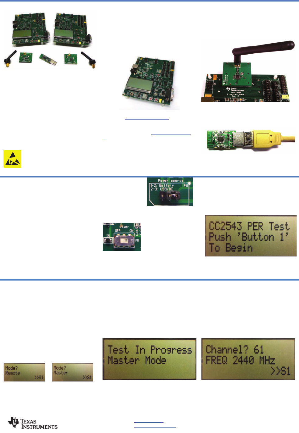
10. Modulation Setup
There are 6 different modulation schemes
available for this application. The different
bitrates are 250 Kbps, 500 Kbps, 1Mbps and 2
Mbps. MSK modulation is used for the 500 Kbps
rate and GFSK for the rest. Move the joystick up
or down to change the scheme and press S1 to
confirm the choice.
11. Packet Length
The packet length can be set to 10, 16, 32, 64 or
120 bytes. Move the joystick up or down to
change the packet length and press S1 to
confirm the choice.
12. Number of Packets
The total number of packets to be sent for each
run can be set to 200, 1000, 5000, 10000 and .
Move the joystick up or down to change the
number of packets and press S1 to confirm the
choice.
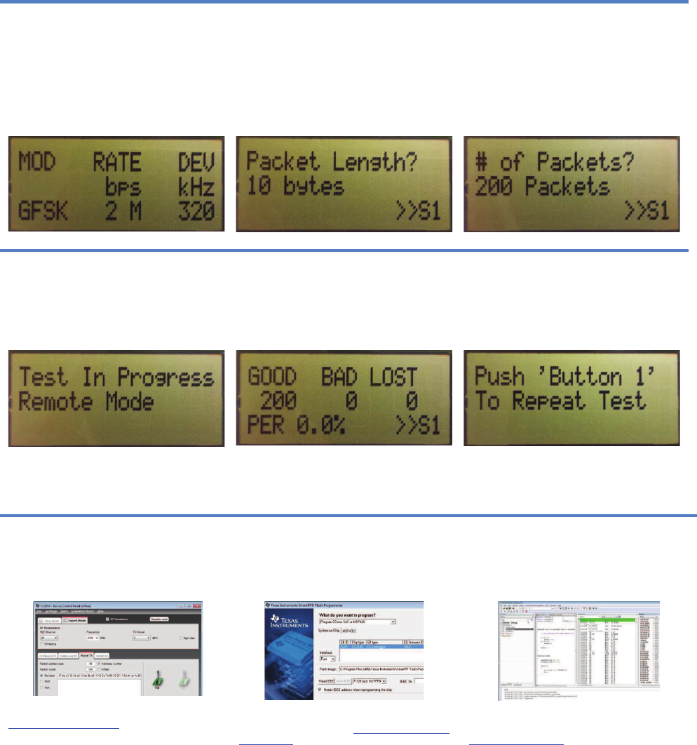
13. Test Running
The remote device acknowledges the beacon
signal from the master and sends the
configuration packet. The PER test begins. While
the master device is sending packets the yellow
led will be lit on the smartRF05EB (“LED3”) or
the red led on the CC2544 Dongle (“LED1”).
14. PER Test Summary
The first results screen will display the number of
packets received without errors (“Good”), the
number that were received with a CRC error
(“Bad”), and the number that were expected but
not received (“LOST”). Push button S1 to
proceed to the second results screen.
15. Repeat Test
The final screen allows the test to be repeated by
pushing “Button 1” (S1). Note that the set up data
is maintained. If you wish to enter different test
parameters, you may do so by pushing “EM
RESET” button, located at the approximate
center of the SmartRF05EB.
Additional Tools and Links
SmartRF™ Studio
SmartRF Studio allows you to configure the radio,
run RF performance tests, and run link tests
between the two SmartRF05EBs.
SmartRF Studio can be downloaded from
www.ti.com/smartrfstudio
SmartRF Flash Programmer
Texas Instruments has a simple tool which can
be used to program and flash the CC2543 and
CC2544.
SmartRF Flash Programmer can be
downloaded from www.ti.com/tool/flash-
programmer
IAR Embedded Workbench
To develop software, program, and debug the
CC2543 and CC2544, you should use IAR
Embedded Workbench for 8051.
More information on IAR EW8051, including a
free evaluation version download, can be found at
www.iar.com/ew8051.

EVALUATION BOARD/KIT/MODULE (EVM) ADDITIONAL TERMS
Texas Instruments (TI) provides the enclosed Evaluation Board/Kit/Module (EVM) under the following
conditions:
The user assumes all responsibility and liability for proper and safe handling of the goods. Further, the user
indemnifies TI from all claims arising from the handling or use of the goods.
Should this evaluation board/kit not meet the specifications indicated in the User’s Guide, the board/ kit may be
returned within 30 days from the date of delivery for a full refund. THE FOREGOING LIMITED WARRANTY IS
THE EXCLUSIVE WARRANTY MADE BY SELLER TO BUYER AND IS IN LIEU OF ALL OTHER
WARRANTIES, EXPRESSED, IMPLIED, OR STATUTORY, INCLUDING ANY WARRANTY OF
MERCHANTABILITY OR FITNESS FOR ANY PARTICULAR PURPOSE. EXCEPT TO THE EXTENT OF THE
INDEMNITY SET FORTH ABOVE, NEITHER PARTY SHALL BE LIABLE TO THE OTHER FOR ANY
INDIRECT, SPECIAL, INCIDENTAL, OR CONSEQUENTIAL DAMAGES.
Please read the User's Guide and, specifically, the Warnings and Restrictions notice in the User's Guide prior to
handling the product. This notice contains important safety information about temperatures and voltages. For
additional information on TI's environmental and/or safety programs, please visit www.ti.com/esh or contact TI.
No license is granted under any patent right or other intellectual property right of TI covering or relating to any
machine, process, or combination in which such TI products or services might be or are used. TI currently deals
with a variety of customers for products, and therefore our arrangement with the user is not exclusive. TI
assumes no liability for applications assistance, customer product design, software performance, or
infringement of patents or services described herein.
Mailing Address: Texas Instruments Post Office Box 655303 Dallas, Texas 75265
Copyright 2011, Texas Instruments Incorporated
REGULATORY COMPLIANCE INFORMATION
As noted in the EVM User’s Guide and/or EVM itself, this EVM and/or accompanying hardware may or may not
be subject to the Federal Communications Commission (FCC) and Industry Canada (IC) rules.
For EVMs not subject to the above rules, this evaluation board/kit/module is intended for use for
ENGINEERING DEVELOPMENT, DEMONSTRATION OR EVALUATION PURPOSES ONLY and is not
considered by TI to be a finished end product fit for general consumer use. It generates, uses, and can radiate
radio frequency energy and has not been tested for compliance with the limits of computing devices pursuant to
part 15 of FCC or ICES-003 rules, which are designed to provide reasonable protection against radio frequency
interference. Operation of the equipment may cause interference with radio communications, in which case the
user at his own expense will be required to take whatever measures may be required to correct this interference.
General Statement for EVMs including a radio
User Power/Frequency Use Obligations: This radio is intended for development/professional use only in legally
allocated frequency and power limits. Any use of radio frequencies and/or power availability of this EVM and its
development application(s) must comply with local laws governing radio spectrum allocation and power limits for
this evaluation module. It is the user’s sole responsibility to only operate this radio in legally acceptable
frequency space and within legally mandated power limitations. Any exceptions to this is strictly prohibited and
unauthorized by Texas Instruments unless user has obtained appropriate experimental/development licenses
from local regulatory authorities, which is responsibility of user including its acceptable authorization.

For EVMs annotated as FCC – FEDERAL COMMUNICATIONS COMMISSION Part 15 Compliant
Caution
This device complies with part 15 of the FCC Rules. Operation is subject to the following two conditions: (1) This
device may not cause harmful interference, and (2) this device must accept any interference received, including
interference that may cause undesired operation.
Changes or modifications not expressly approved by the party responsible for compliance could void the user's
authority to operate the equipment.
FCC Interference Statement for Class A EVM devices
This equipment has been tested and found to comply with the limits for a Class A digital device, pursuant to part
15 of the FCC Rules. These limits are designed to provide reasonable protection against harmful interference
when the equipment is operated in a commercial environment. This equipment generates, uses, and can radiate
radio frequency energy and, if not installed and used in accordance with the instruction manual, may cause
harmful interference to radio communications. Operation of this equipment in a residential area is likely to cause
harmful interference in which case the user will be required to correct the interference at his own expense.
FCC Interference Statement for Class B EVM devices
This equipment has been tested and found to comply with the limits for a Class B digital device, pursuant to part
15 of the FCC Rules. These limits are designed to provide reasonable protection against harmful interference in
a residential installation. This equipment generates, uses and can radiate radio frequency energy and, if not
installed and used in accordance with the instructions, may cause harmful interference to radio
communications. However, there is no guarantee that interference will not occur in a particular installation. If this
equipment does cause harmful interference to radio or television reception, which can be determined by turning
the equipment off and on, the user is encouraged to try to correct the interference by one or more of the following
measures:
• Reorient or relocate the receiving antenna.
• Increase the separation between the equipment and receiver.
• Connect the equipment into an outlet on a circuit different from that to which the receiver is connected.
• Consult the dealer or an experienced radio/TV technician for help.

For EVMs annotated as IC – INDUSTRY CANADA Compliant
This Class A or B digital apparatus complies with Canadian ICES-003.
Changes or modifications not expressly approved by the party responsible for compliance could void the user’s
authority to operate the equipment.
Concerning EVMs including radio transmitters
This device complies with Industry Canada licence-exempt RSS standard(s). Operation is subject to the
following two conditions: (1) this device may not cause interference, and (2) this device must accept any
interference, including interference that may cause undesired operation of the device.
Concerning EVMs including detachable antennas
Under Industry Canada regulations, this radio transmitter may only operate using an antenna of a type and
maximum (or lesser) gain approved for the transmitter by Industry Canada. To reduce potential radio
interference to other users, the antenna type and its gain should be so chosen that the equivalent isotropically
radiated power (e.i.r.p.) is not more than that necessary for successful communication.
This radio transmitter has been approved by Industry Canada to operate with the antenna types listed in the
user guide with the maximum permissible gain and required antenna impedance for each antenna type
indicated. Antenna types not included in this list, having a gain greater than the maximum gain indicated for that
type, are strictly prohibited for use with this device.
~
Cet appareil numérique de la classe A ou B est conforme à la norme NMB-003 du Canada.
Les changements ou les modifications pas expressément approuvés par la partie responsable de la conformité
ont pu vider l’autorité de l'utilisateur pour actionner l'équipement.
Concernant les EVMs avec appareils radio
Le présent appareil est conforme aux CNR d'Industrie Canada applicables aux appareils radio exempts de
licence. L'exploitation est autorisée aux deux conditions suivantes : (1) l'appareil ne doit pas produire de
brouillage, et (2) l'utilisateur de l'appareil doit accepter tout brouillage radioélectrique subi, même si le brouillage
est susceptible d'en compromettre le fonctionnement.
Concernant les EVMs avec antennes détachables
Conformément à la réglementation d'Industrie Canada, le présent émetteur radio peut fonctionner avec une
antenne d'un type et d'un gain maximal (ou inférieur) approuvé pour l'émetteur par Industrie Canada. Dans le
but de réduire les risques de brouillage radioélectrique à l'intention des autres utilisateurs, il faut choisir le type
d'antenne et son gain de sorte que la puissance isotrope rayonnée équivalente (p.i.r.e.) ne dépasse pas
l'intensité nécessaire à l'établissement d'une communication satisfaisante.
Le présent émetteur radio a été approuvé par Industrie Canada pour fonctionner avec les types d'antenne
énumérés dans le manuel d’usage et ayant un gain admissible maximal et l'impédance requise pour chaque
type d'antenne. Les types d'antenne non inclus dans cette liste, ou dont le gain est supérieur au gain maximal
indiqué, sont strictement interdits pour l'exploitation de l'émetteur.

Important Notice for Users of this Product in Japan
This development kit is NOT certified as Confirming to Technical Regulations of
Radio Law of Japan!
If you use this product in Japan, you are required by Radio Law of Japan to follow the instructions below with
respect to this product:
(1) Use this product in a shielded room or any other test facility as defined in the notification #173
issued by Ministry of Internal Affairs and Communications on March 28, 2006, based on Sub-section 1.1 of
Article 6 of the Ministry’s Rule for Enforcement of Radio Law of Japan,
(2) Use this product only after you obtained the license of Test Radio Station as provided in Radio Law
of Japan with respect to this product, or
(3) Use of this product only after you obtained the Technical Regulations Conformity Certification as
provided in Radio Law of Japan with respect to this product.
Also, please do not transfer this product, unless you give the same notice above to the transferee.
Please note that if you could not follow the instructions above, you will be subject to penalties of Radio Law of
Japan.
Texas Instruments Japan Limited
(address) 24-1, Nishi-Shinjuku 6 chome, Shinjukku-ku, Tokyo, Japan
http://www.tij.co.jp
!"#$%&'()*+,
!"#$%&'()*+, !"#$%&'()*+,
!"#$%&'()*+,
-./0123456789:;<=>)?@ABCD
-./0123456789:;<=>)?@ABCD-./0123456789:;<=>)?@ABCD
-./0123456789:;<=>)?@ABCD
-EF*"#$%GH)3IJKLMN*'OIPQ*RSTU*VW<X()R'YZ[\]&@A^*
_"+,ZY`RD
abcJKLdefgh6ih1jh1k%6lZmn18o3p28qrstuvh173k_wOxT'J
Kyz{*|}~_"#$R'YZD
ac}*<X"#$R'YZD
ac456789:;<X"#$R'YZD
?I-EF3I*"#$%&'()*+,<I%HR@II_
R*HA^D
<MN>R93IJKL*g]8$`T]&<"¡,ZY`RD
q-¢0£¤¥¦§¤¨©ª§¨«¬®
q-¢0£¤¥¦§¤¨©ª§¨«¬®q-¢0£¤¥¦§¤¨©ª§¨«¬®
q-¢0£¤¥¦§¤¨©ª§¨«¬®
¯°±²³´µ²³¶·¸¹ºbk
¯°±²³´µ²³¶·¸¹ºbk¯°±²³´µ²³¶·¸¹ºbk
¯°±²³´µ²³¶·¸¹ºbk
µ²³»¼½©
µ²³»¼½©µ²³»¼½©
µ²³»¼½©
http://www.tij.co.jp
EVALUATION BOARD/KIT/MODULE (EVM)
WARNINGS, RESTRICTIONS AND DISCLAIMERS
For Feasibility Evaluation Only, in Laboratory/Development Environments. Unless otherwise indicated,
this EVM is not a finished electrical equipment and not intended for consumer use. It is intended solely for use
for preliminary feasibility evaluation in laboratory/development environments by technically qualified electronics
experts who are familiar with the dangers and application risks associated with handling electrical mechanical
components, systems and subsystems. It should not be used as all or part of a finished end product.
Your Sole Responsibility and Risk. You acknowledge, represent and agree that:
1. You have unique knowledge concerning Federal, State and local regulatory requirements (including but
not limited to Food and Drug Administration regulations, if applicable) which relate to your products and
which relate to your use (and/or that of your employees, affiliates, contractors or designees) of the EVM for
evaluation, testing and other purposes.
2. You have full and exclusive responsibility to assure the safety and compliance of your products with all
such laws and other applicable regulatory requirements, and also to assure the safety of any activities to
be conducted by you and/or your employees, affiliates, contractors or designees, using the EVM. Further,
you are responsible to assure that any interfaces (electronic and/or mechanical) between the EVM and any
human body are designed with suitable isolation and means to safely limit accessible leakage currents to
minimize the risk of electrical shock hazard.
3. You will employ reasonable safeguards to ensure that your use of the EVM will not result in any property
damage, injury or death, even if the EVM should fail to perform as described or expected.
4. You will take care of proper disposal and recycling of the EVM’s electronic components and packing
materials
Certain Instructions. It is important to operate this EVM within TI’s recommended specifications and
environmental considerations per the user guidelines. Exceeding the specified EVM ratings (including but not
limited to input and output voltage, current, power, and environmental ranges) may cause property damage,
personal injury or death. If there are questions concerning these ratings please contact a TI field representative
prior to connecting interface electronics including input power and intended loads. Any loads applied outside of
the specified output range may result in unintended and/or inaccurate operation and/or possible permanent
damage to the EVM and/or interface electronics. Please consult the EVM User's Guide prior to connecting any
load to the EVM output. If there is uncertainty as to the load specification, please contact a TI field
representative. During normal operation, some circuit components may have case temperatures greater than
60 C as long as the input and output are maintained at a normal ambient operating temperature. These
components include but are not limited to linear regulators, switching transistors, pass transistors, and current
sense resistors which can be identified using the EVM schematic located in the EVM User's Guide. When
placing measurement probes near these devices during normal operation, please be aware that these devices
may be very warm to the touch. As with all electronic evaluation tools, only qualified personnel knowledgeable
in electronic measurement and diagnostics normally found in development environments should use these
EVMs
Agreement to Defend, Indemnify and Hold Harmless. You agree to defend, indemnify and hold TI, its
licensors and their representatives harmless from and against any and all claims, damages, losses, expenses,
costs and liabilities (collectively, "Claims") arising out of or in connection with any use of the EVM that is not in
accordance with the terms of the agreement. This obligation shall apply whether Claims arise under law of tort
or contract or any other legal theory, and even if the EVM fails to perform as described or expected.
Safety-Critical or Life-Critical Applications. If you intend to evaluate the components for possible use in
safety critical applications (such as life support) where a failure of the TI product would reasonably be expected
to cause severe personal injury or death, such as devices which are classified as FDA Class III or similar
classification, then you must specifically notify TI of such intent and enter into a separate Assurance and
Indemnity Agreement.