Texas Instruments ACS6420 Vicinity Card RFID Reader User Manual Pre12 6 2002
Texas Instruments Inc Vicinity Card RFID Reader Pre12 6 2002
Contents
- 1. Users Manual 1
- 2. Users Manual 2
Users Manual 1

1
Getting Started Guide
Thank you for your recent purchase of the Texas Instruments™ RFID Systems’
Series 6400 Access Control Evaluation Kit. This Kit enables integrators to rapidly
incorporate our proven 13.56 MHz contact-less technology into existing security
applications, as well as design it into new applications.
We’re pleased to serve the “Access Control” market with a RFID product that
boasts read/program capability through RS-485 serial data communications, while
still offering backwards comp atibility with the widely adopted Wiegand protocol
standard. The added value of higher security UID-based data encryption ensures
card uniqueness, and makes card copying using conventional methods virtually
impossible.
This Getting Started Guide provides simple step-by-step instructions to get the user
up and running quickly. More detailed information including hardware and
protocol descriptions can be found both on the included software CD and on the TI-
RFid ™ website @ www.ti-rfid.com
Contents
1. General................................................................................................................................. 2
2. Evaluation Kit Contents .................................................................................................... 3
3. Setup & Test - Self-Run Mode......................................................................................... 4
4. Connecting to a Wiegand Security Panel....................................................................... 5
5. Connecting a Single Reader to a Computer................................................................... 5
6. Software Installation .......................................................................................................... 6
7. Software Functionality Test (One Reader)..................................................................... 6
8. Basic ISO/IEC 15693 Software Commands.................................................................. 7
9. The Software Toolbar ........................................................................................................ 9
10. Multi-drop Addressing.................................................................................................. 10
11. Wiring Alternatives for Lights and Sound................................................................. 11
12. Self-Test Mode ............................................................................................................... 11
13. A Word About Encryption............................................................................................ 12
14. References ....................................................................................................................... 12
15. Additional Resources..................................................................................................... 12
16. Troubleshooting.............................................................................................................. 13
17. Regulations...................................................................................................................... 14
© Copyright Texas Instruments. 2002.
All rights reserved.
Windows is a registered trademark of Microsoft Corporation in the United States and/or other counties.
11-06-22-709 12/2002
* Information submitted for FCC, Industry Canada, RTTE, CE &
ETL certification: A92ACS6410 & A92ACS6420 *

2
1. General
Texas Instruments’ Series 6400 Evaluation Kit is designed to help the user explore
the advanced capabilities of the 6400 Series Access Control Reader family in
conjunction with TI-RFid’s ISO/IEC 15693 compliant badges.
The Series 6400 readers are ISO/IEC 15693 compliant, and are therefore compatible
with Tag-it ™ HF-I badges, as well as other ISO/IEC 15693 compliant tags and
cards.
S6400 Reader Family
Information stored on an ISO/IEC 15693 compliant badge is organized into 64
blocks, each containing 4 bytes of data. (1 byte = 1 ASCII character.) Blocks can
be programmed, re -programmed, viewed, and locked to prevent reprogramming.
The following are just a few of the RFID operations (and their ISO/IEC 15693
equivalent commands) that can be performed on cards and tags with this kit:
• Identify (Inventory) All Cards in field.
• View (Read) One Block of data on card.
• View Many (Read Multiple) Blocks of data at once.
• Program (Write) One Block of data on card.
• Program Many (Write Multiple) Blocks of data at once
• Lock One Block of data.
• Lock Many (Lock Multiple) Blocks of data.
* Information submitted for FCC, Industry Canada,
RTTE, CE & ETL certification: A92ACS6410 &
A92ACS6420 *
3
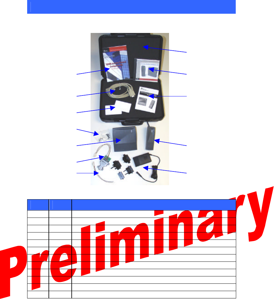
2. Evaluation Kit Contents
The evaluation kit includes the following components:
12
10 9
6 11
8
7
1 2
4
5 3
S6400 Series Evaluation Kit
Item
Qty.
Description
1 1 S6410 Wall Plate Reader
2 1 S6420 Mullion Reader
3 1 Universal Power Supply with Global Adapters
4 1 Harness with RS-485/RS-232 Converter
5 1 Harness with Wire Leads
6 1 Serial Data RS-232 Cable
7 2 Mounting Hardware Packs
8 5 ISO 15693 Compliant Programmable Badges (Pre-programmed)
9 1 Software Demo CD
10 1 Getting Started Guide (This Guide)
11 1 Installation Guide
12 1 Carrying Case
If any of the listed items are missing from this kit, please contact technical support.
* Information submitted for FCC, Industry Canada,
RTTE, CE & ETL certification: A92ACS6410 &
A92ACS6420 *

4
3. Setup & Test - Self-Run Mode
The S6400 readers are shipped in the factory-default “Self-Run” (Wiegand data
output) mode, allowing them to operate independently of a computer or security
control panel. Follow the instructions below to activate the readers in this mode and
verify their functionality.
1. Connect the harness with the RS-485 converter to one reader. The RS-485
converter is not needed for this test, however the harness includes a
receptacle for the power supply, which is required.
Note:
Be sure that the remaining unconnected wires do not touch each
other, as this may cause operation in “Self Run” mode to fail.
2. Connect the power supply to the power connector on the RS-485 converter
harness.
Caution:
The connector on the power supply must be set at positive tip or
interior output voltage. Be sure the arrow on the tip of the power
supply is lined up with the (-) setting on the power supply output
barrel indicating negative barrel (positive tip) voltage.
3. Plug the power supply into an AC power source using the appropriate
adapter supplied.
4. Test reader by slowly bringing one of the pre-programmed ISO/IEC 15693
compliant badges within close range of the reader. As soon as the badge is
within the reader’s range, the reader will beep and the LED will flash once
to indicate a successful read has taken place.
* Information submitted for FCC, Industry Canada,
RTTE, CE & ETL certification: A92ACS6410 &
A92ACS6420 *
5
4. Connecting to a Wiegand Security Panel
The S6400 readers are designed to work with any security controller which follows
the Wiegand protocol standard. All readers are placed in Self-Run (Weigand data
output) mode upon shipment, thus they are “ready out of the box” for connection to
a Wiegand security panel. A harness with tinned wire leads is included to simplify
connection to a Wiegand security panel.
Follow the security panel manufacturer’s instructions to connect the reader to the
panel, using the following wiring guide as a reference. The essential connections
are necessary for proper operation and data transfer in Self-Run mode. For more
information regarding the optional connections, refer to the S6400 User’s Guide
(11-06-21-711).
Essential Connections
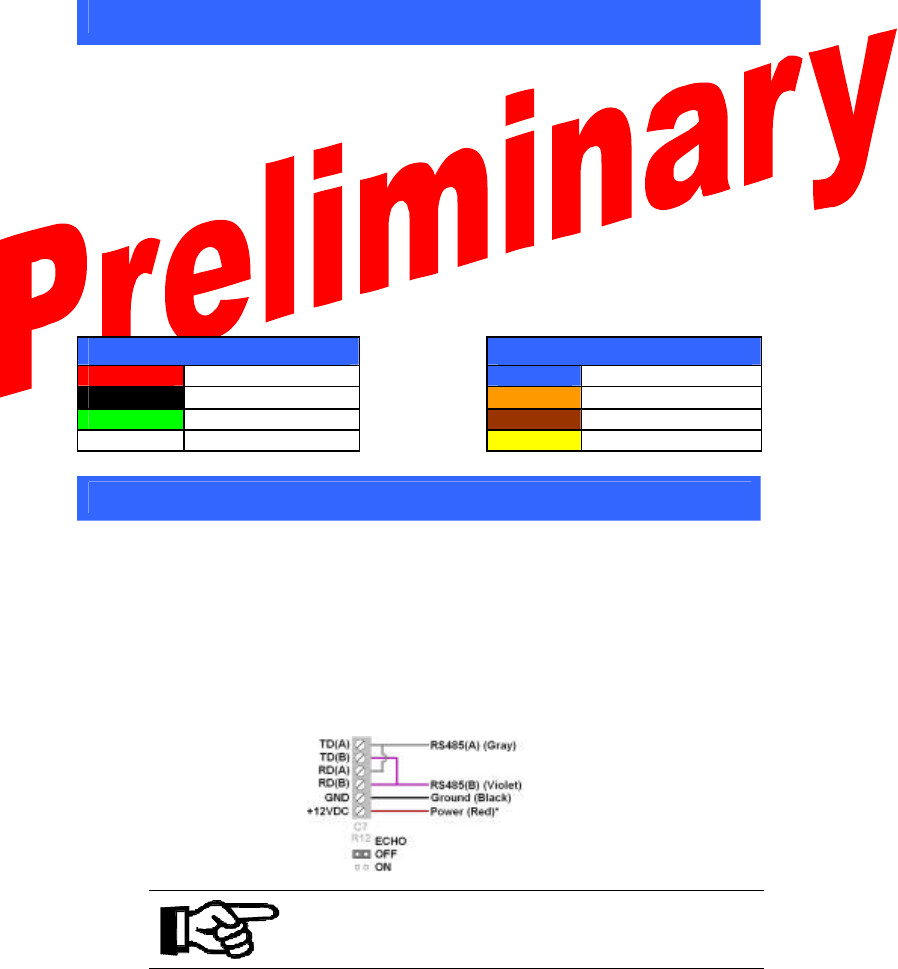
Optional Connections
Red Power (9-14 VDC) Blue Hold
Black Ground Orange Green LED
Green Wiegnad Data(0) Brown Red LED
White Wiegand Data(1) Yellow Audio
5. Connecting a Single Reader to a Computer
Programming and locking data on a badge requires two-way communication, which
can be achieved by operating the reader in host-driven mode. The included RS-
485/RS-232 converter and host software allow the reader to operate in this mode
using a PC as the host.
1. Follow the setup procedure in section 3 to verify reader functionality.
2. Verify proper connection of the RS-485/RS-232 converter to the reader
using the following diagram as a reference.
Note:
Observe the proper orientation of the jumper on the RS-485/RS-232
Converter - it must be set to “echo off”.
3. Connect the RS-485 Converter to the computer’s serial port using the serial
cable provided.
* Information submitted for FCC, Industry Canada,
RTTE, CE & ETL certification: A92ACS6410 &
A92ACS6420 *

6
6. Software Installation
The S6400 Series software application demonstrates the readers’ features that are
available through the RS-485/RS-232 serial link.
At minimum, the software requires the following:
• 3.5 MB available hard disk space
• Windows 98 SE or later
The software can be installed from the included CD:
D:\software\setup.exe
(where “D” is the assumed drive letter of the active CD-ROM drive.)
Double-click “setup.exe” to begin the installation.
Follow the prompts to complete the installation.
The software can also be downloaded directly from the website:
http://www.ti.com/tiris/docs/products/tools.shtml
Download “S6400_Utility_Software.zip”
Un-zip the files and double-click “setup.exe” to install.
Upon installation, double-click on the S6400 Utility Software icon to run the
software.
7. Software Functionality Test (One Reader)
1. Follow the setup procedure in section 5 and the software installation
procedure in section 6.
2. Run the software by double-clicking the S6400 Utility Software icon.
3. From the Communications Menu, select the COM port to which the reader
is connected. The default port is COM1.
4. Select the desired baud rate from the Communications Menu. The default
baud rate is 38400.
5. Press the Setup button to view reader’s current state.
6. Press the Version button to view the reader’s serial number and firmware
version.
Note:
Firmware version 2.0 was in effect as of the printing of this guide. If
the version displayed is higher than version 2.0, it is recommended to
check for a newer version of this guide, as new features may have
been added. The most recent versions can be downloaded from the
document center @ www.ti-rfid.com.
* Information submitted for FCC, Industry Canada,
RTTE, CE & ETL certification: A92ACS6410 &
A92ACS6420 *

7
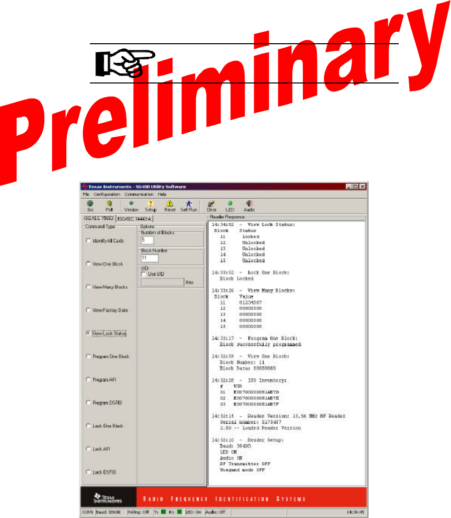
8. Basic ISO/IEC 15693 Software Commands
The host software allows data to be viewed and programmed in hexadecimal
format. Executing the following commands in order will help you familiarize
yourself with the software interface. Sample output can be seen in the graphic on
the following page.
Note:
Be sure the “ISO/IEC 15693” tab (under the “Go” button) is selected.
For information regarding the ISO/IEC 14443 tab, consult the User’s
Guide.
Identify All Cards in field:
1. Place one or more badges in the read field.
2. Select “Identify All Cards” to display the UID number of each badge in the
field.
3. Click “Go”.
View One Block of data on card:
1. Place a badge in the read field.
2. Select “View One Block” and enter the desired block number in the block
number field.
3. Click “Go”.
Program One Block of data on card:
1. Place a badge in the read field.
2. Select “Program One Block”
3. Enter the desired block number and the data to be entered in the
appropriate fields.
4. Click “Go”.
5. Repeat the “View One Block” process to verify that data has been written.
Note:
The badges included with th is kit have encrypted data pre-
programmed into blocks 0-4, which demonstrates the customizable
functionality of the Wiegand card data output mode. To avoid
destroying this data, do not reprogram blocks 0-4.
View Many Blocks of data at once:
1. Place a badge in the read field.
2. Select “View Many Blocks”
3. Enter the desired number of consecutive blocks (up to 32 blocks), and the
starting block in the appropriate fields.
4. Click “Go”.
* Information submitted for FCC, Industry Canada,
RTTE, CE & ETL certification: A92ACS6410 &
A92ACS6420 *
8
Lock One Block:
1. Place a badge in the read field.
2. Select “Lock One Block” and enter the block number to be locked.
3. Click “Go”.
Note:
Once a block has been locked, the data in that block is secure and can
NEVER be changed. When locking blocks, a confirmation box will
appear, as the action is irreversible.
View Lock Status of blocks:
1. Place a badge in the read field.
2. Select “View Lock Status”
3. Enter the desired number of consecutive blocks, and the starting block in
the appropriate fields.
4. Click “Go”.
Expected Results of Executed Commands
* Information submitted for FCC, Industry Canada,
RTTE, CE & ETL certification: A92ACS6410 &
A92ACS6420 *
9
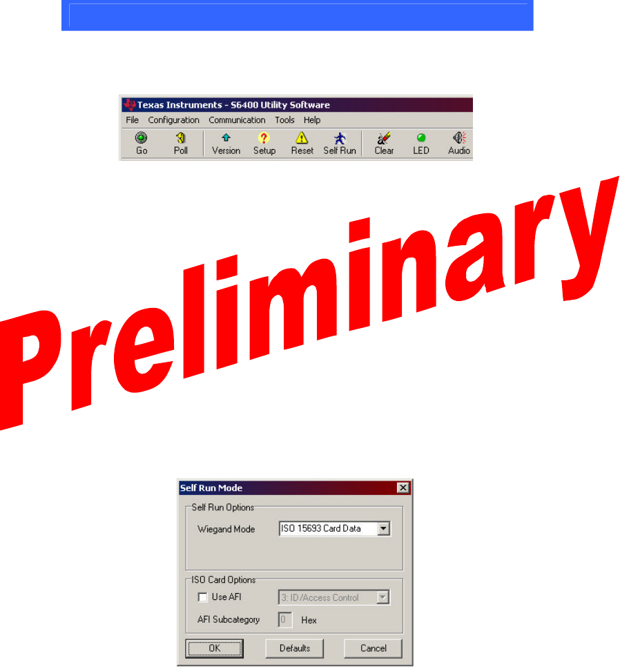
9. The Software Toolbar
Frequently used commands are implemented into the toolbar at the top of the Host
Software window.
S6400 Utility Software Toolbar
The “Go” button is used to execute the selected command.
To continuously execute a command, select the “Poll” button prior to clicking
“Go.” The “Poll” (continuous) option will remain activated until it is “Stopped.”
Clicking the “Version” button will cause the reader version, serial number, and
reader firmware version to be displayed.
Clicking the “Setup” button causes the baud rate, LED status, audio status, RF
transmitter status, and Wiegand status to be displayed.
The “Reset” button initializes the reader in a manner similar to cycling power. It
resets specific parameters, but leaves some customizable parameters untouched. If
ever a command is issued that causes the reader to stop responding, try clicking the
“Reset” button.
Clicking the “Self Run” button brings up the Self-Run window.
Self-Run Mode Window
When placed in the default Self-Run mode, the unit outputs card data over the
Wiegand data lines. The default setting is “ISO 15693 Card Data”. Selecting a
* Information submitted for FCC, Industry Canada,
RTTE, CE & ETL certification: A92ACS6410 &
A92ACS6420 *
10
specific AFI (Application Family Identifier) will set a restriction, allowing only
badges with the specifically selected AFI to be read.
Note:
Once a command has been issued over the RS-485 communication
link, the unit will cease to operate in Wiegand (Self Run) mode. To
return to Wiegand mode, click the “Self Run” button. Choose “ISO
15693 UID Card Data” (default) from the drop-down menu, and click
“OK”.
Click the “Clear” button to clear the contents of the “Reader Response” window.
Note:
Data is buffered in the “Reader Response” window and can be
reviewed by use of the scroll bar. As the buffer fills up, the software
can become slow to respond. If the system seems to lag, try clearing
this buffer by clicking the “Clear” button.
The “LED” and “Audio” buttons toggle the LED and Audio beeper response on
and off, respectively.
The LEDs and audio transducer can also be individually activated through the host
software using the “Activate” command from the file menu. LED color can be
specified, along with activation duration in milliseconds.
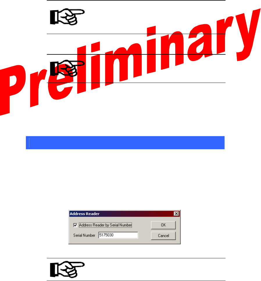
10. Multi-drop Addressing
Reader serial number addressing allows multiple Readers (up to 100) to be operated
in parallel on a single RS-485 bus. With multiple readers attached to the RS-485
bus, each reader can be individually addressed using the “Address Reader”
command in the “Configuration” menu. In the window that appears (shown below),
checking the “Address Reader by Serial Number” box, and entering the serial
number for a specific reader on the bus causes all issued commands to be directed to
that reader alone.
Reader Address Window
Note:
With multiple readers attached to the RS-485 bus, commands should
not be issued unless a specific reader is addressed, as the readers do
not currently support the use of “broadcast” commands.
To turn off reader addressing, uncheck the “address Reader by Serial Number” box.
* Information submitted for FCC, Industry Canada,
RTTE, CE & ETL certification: A92ACS6410 &
A92ACS6420 *

11
11. Wiring Alternatives for Lights and Sound
Several operational alternatives exist for the LEDs and the audio transducer. The
following table lists the associated wires.
Optional Connections
Orange Green LED
Brown Red LED
Yellow Audio
Tying any of these wires to ground while the unit is powered will cause activation
of the associated feature. For example, many existing readers have an LED which
glows red by default when the reader is at rest. Tying the brown wire permanently
to ground will cause the S6400 reader to have the same effect. In this state, upon
activation by a card, the light will momentarily switch to green, and then back to
red.
As another example, if the unit is tied to a controller, which momentarily unlocks a
door, it may be desired to have the green light glow and the audio transducer sound
for the duration in which the door is unlocked. Tying the yellow and orange wires
to the (-) controller output to which the door lock is connected will produce this
effect.
For more information regarding the optional wiring connections, including the hold
feature, consult the User’s Guide.
12. Self-Test Mode
The readers are equipped with a self-test mode that allows them to cycle through
their functions and report the results through the LED. To put the reader into self-
test mode, connect the following wire pairs together, then apply power to the reader.
Wire: Green Violet White Blue
Connect To:
Orange Brown Yellow Gray
Proper operation is indicated by the LED blinking green. The LED will turn to
solid red and the unit will beep once within three seconds after a card is brought into
the field. The flashing green light will return once the card has been removed from
the field. See the User’s Guide for more information about self-test mode.
CAUTION:
The unit is not intended to operate in self-test mode
indefinitely, as it operates above its standard duty-
cycle.
Leaving a badge in the field longer than 3 minutes while the
unit is in self-test mode may cause the unit to overheat.
* Information submitted for FCC, Industry Canada,
RTTE, CE & ETL certification: A92ACS6410 &
A92ACS6420 *

12
13. A Word About Encryption
“Wiegand Card Data” mode takes advantage preprogrammed DES encryption.
Each reader is loaded with a proprietary master encryption key which is used to
decrypt the data stored in blocks 0-4 of the preprogrammed badges. Card
Programming software can be purchased separately, allowing the user to program
badges using either the default master key, or a custom key. Badges programmed
using a custom key can be read in “Card Data” mo de so long as the custom key is
selected and entered in the “Encryption” option under the “Configuration” menu.
14. References
For more information please refer to the following documentation available for
download from the Document Center on the TI-RFid website:
http://www.ti-rfid.com
Spec No. Title
11-06-21-711 S6400 User’s Guide
11-06-21-712 S6400 Reference Manual
11-06-21-713 S6410/S6420 Installation Guide
15. Additional Resources
1-888-937-6536
USA +1 (972)-575-4364
Please contact TI-RFid technical support service if
you have any questions. Hours are Monday through
Friday 8am-5pm CST. e-mail rfidsupport@ti.com
Belgium (English) +32 (0)2 7455455
France (English)
+33 4 93 22 22 00
Germany
+49 (0)8161 80 2200
Italy
+39 (0)39 6568 210
Netherlands (English)
+31 (0)546 879 222
Spain
+34 902 19 73 96
Sweden (English)
+46 (0) 8 58755527
U.K.
+44 (0) 1604 88 4088
International Support Numbers:
e-mail e-rfidsupport@ti.com
Notice: Texas Instruments (TI) reserves the right to make changes to its products or services and/or to
discontinue any product or service at any time without notice. TI provides customer assistance in various
technical areas, but does not have full access to data concerning the use and applications of customer’s
products. Therefore, TI assumes no liability and is not responsible for customer applications, product or
software design, and performance issues relating to systems or applications incorporating TI products. In
addition, TI assumes no liability and is not responsible for infringement of patents and/or any other
intellectual or industrial property rights of third parties that may result from assistance provided by TI. TI
products are not designed, intended, authorized, or warranted to be suitable for life support applications
or any other life critical applications that could involve potential risk of death, personal injury, or severe
property or environmental damage.
* Information submitted for FCC, Industry Canada,
RTTE, CE & ETL certification: A92ACS6410 &
A92ACS6420 *

13
16. Troubleshooting
This guide outlines some of the common issues experienced with the S6400 reader and host
software. Please contact Technical Support for issues that are not addressed here.
Symptom Cause Remedy
Verify power supply is properly connected
Power issue Disconnect and reapply power to reader
Incompatible,
damaged, or
un-programmed
badge
Try another ISO/IEC-15693 preprogrammed
badge
Reader does not
function in Self-Run
or Wiegand mode
Reader not set in
Self-run mode Connect to PC and use host software to set the
reader in Self -Run mode (p. 9)
Verify power supply is properly connected
Power issue Disconnect and reapply power to reader
Serial cable
connected
improperly
Verify serial cable is properly connected to RS-
485 converter and computer’s COM port
Incorrect COM port
selected Select correct COM port in software to which
the reader is connected (p. 6)
Sequence through available baud rates in
software until reader responds, then select
desired rate (p. 6)
Incorrect baud rate
selected Hit the “Reset” button and cycle through baud
rates again (p. 9)
PC does not
recognize reader
(Error: Message
Timeout occurs)
Addressing turned
on/Address set
incorrectly
Turn off Reader Addressing in Configuration
munu, or set address value to correct reader
serial number (p. 10)
Reader responds
incorrectly to
software
commands,
firmware version is
displayed
incorrectly
Echo jumper on
RS-485 converter
set improperly
Remove echo jumper on RS-485 converter and
place over pins marked “echo off” (p. 5)
“View Many
Blocks” reports
“command not
supported by
reader”
Too many blocks
selected for multi-
block view
Only 32 blocks can be read at a time. Select
32 or fewer blocks and execute command
again
Self-Run set to
“Card Data” -
Reader expects
pre-programmed
badge
To read ALL ISO/IEC 15693 tags, click “Self -
Run” button, and select “ISO 15693 UID 26 bit”
Only certain
ISO/IEC 15693
badges recognized
in Wiegand/Self
Run Mode Reader set to
recognize specific
AFI
Click “Self Run” button, and select the desired
Application Family Identifier (AFI). 30 is the
standard AFI for Identification/Access Control.
Uncheck “Use AFI” to allow the reader to
recognize all ISO-15693 compliant cards in
Wiegand mode
* Information submitted for FCC, Industry Canada,
RTTE, CE & ETL certification: A92ACS6410 &
A92ACS6420 *

14
17. Regulations
The S6400 system comprises a RF transmission device, and is therefore subject to
national and international regulations. TI has obtained approvals from approval
authorities in a number of countries and is continuing to apply for approvals in
further countries. Actual status can be advised by customer support. In countries
where approval has not been obtained, this system may be operated only under an
experimental license issued by the relevant approval authority and must not be
marketed. Before any such device or system can be marketed, an equipment
authorization must be obtained from the relevant approval authority.
FCC Notices (U.S.A.)
This equipment has been tested and found to comply with the limits for a Class A
digital device and intentional radiator, pursuant to Part 15 of the FCC Rules. These
limits are designed to provide reasonable protection against harmful interference
when the equipment is operated in a commercial environment. This equipment
generates, uses, and can radiate radio frequency energy and if not installed and used
in accordance with the instruction manual, may cause harmful interference to radio
communications. Operation of this equipment in a residential area is likely to cause
harmful interference in which case the user will be required to correct the
interference at his/her expense.
Modifications to this device shall not be made without the written consent of Texas
Instruments Incorporated. Unauthorized modifications may void the authority
granted under Federal Communications Commission Rules permitting the operation
of this device.
CE Conformity (Europe)
A CE Declaration of Conformity is available for this system through customer
support. Any device or system incorporating the S6400 reader system, in full or in
part, in any other than the originally tested configuration needs to be verified against
the European EMC directive. The System Integrator or user of such a system prior
to marketing and operating it in European Community must issue a separate
Declaration of Conformity.
For more information regarding regulations and endorsements, including CE, ETL,
and FCC, please contact technical support directly.
* Information submitted for FCC, Industry Canada,
RTTE, CE & ETL certification: A92ACS6410 &
A92ACS6420 *
Information submitted for FCC, Industry Canada, R&TTE, CE & ETL certifications- FCC ID: A92ACS6420
5. Supplemental Information to be in the Reader or System Manual
In addition to reiteration of required information as on intentional radiator, in keeping
with sections 15.21 and 15.105 of the FCC rules, the manual supplied with the reader will also
include the following admonitions:
NOTE: This equipment has been tested and found to comply with the limits for a Class B digital
device, pursuant to Part 15 of the FCC Rules. These limits are designed to provide reasonable
protection against harmful interference in a residential installation. This equipment generates,
uses and can radiate radio frequency energy and, if not installed and used in accordance with the
instructions, may cause harmful interference to radio communications. However, there is no
guarantee that interference will not occur in a particular installation. If this equipment does cause
harmful interference to radio or television reception, which can be determined by turning the
equipment off and on, the user is encouraged to try to correct the interference by one or more of
the following measures:
• Reorient or relocate the receiving antenna.
• Increase the separation between the equipment and receiver.
• Connect the equipment into an outlet on a circuit different from that to which the receiver is
connected.
• Consult the dealer or an experienced radio technician for help.
NO MODIFICATIONS: Modifications to this device shall not be made without the
written consent of Texas Instruments Incorporated. Unauthorized modifications may void the
authority granted under Federal Communications Commission Rules permitting the operation of
this device.