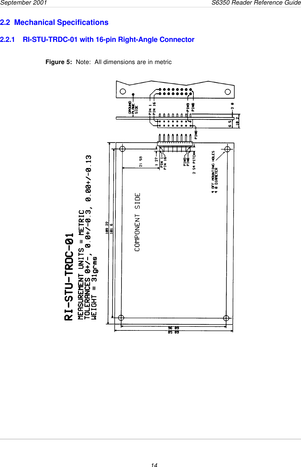
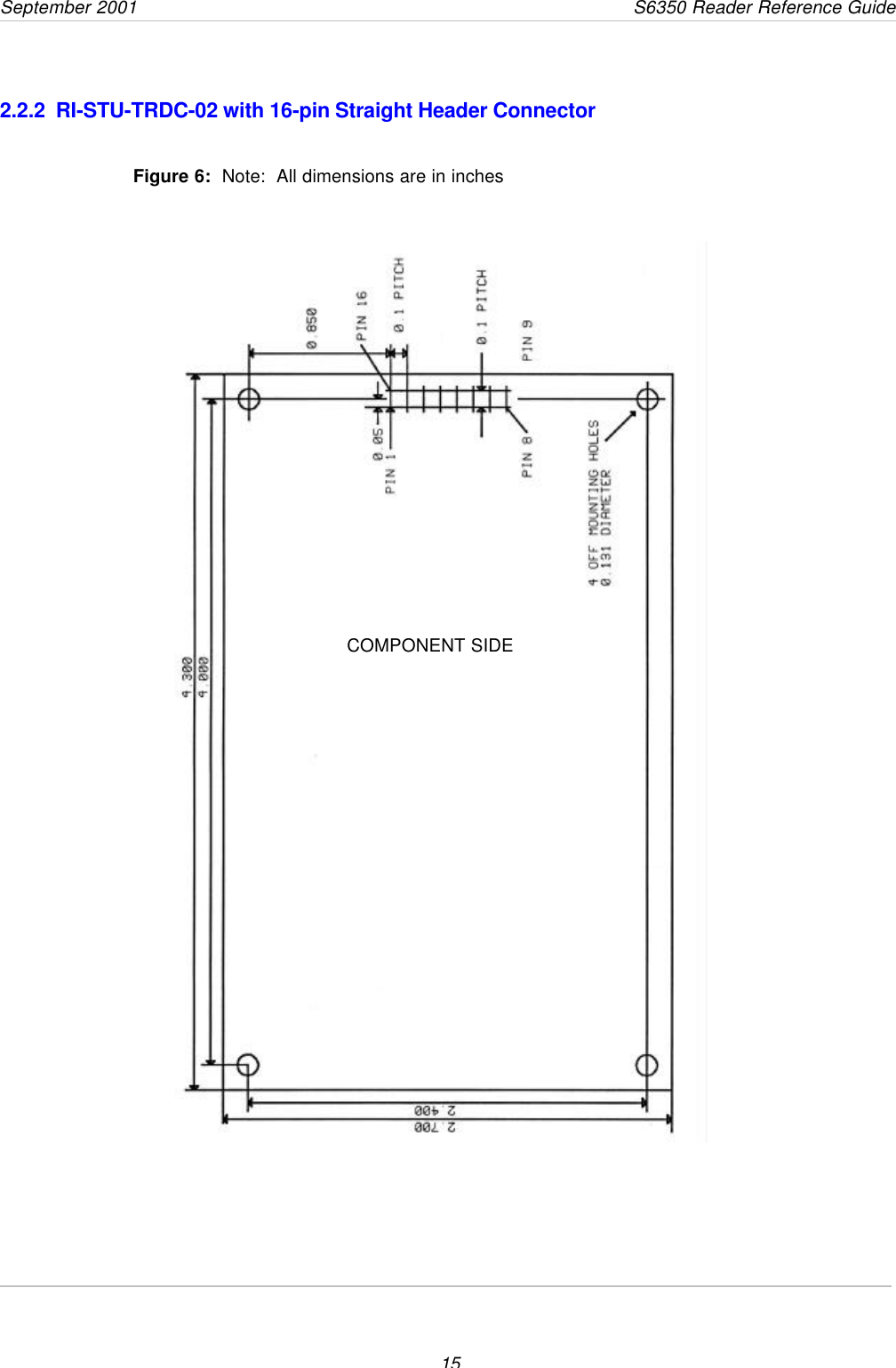
Texas Instruments HFDEMOKITII Inductive Tag Reader User Manual 11 06 21 700

Texas Instruments Inc Inductive Tag Reader 11 06 21 700

Manual

1HF Reader System Series 6000      S6350 Multi-Protocol Reader Modules: RI-STU-TRDC-01 & 02Reference Guide11-06-21-700         September 2001 A TEXAS INSTRUMENTS TECHNOLOGY
September 2001                 S6350 Reader Reference Guide                      2     Second Edition - September 2001This is the second edition of this manual.  It describes the  S6350 Reader (formerlypublished as the Series 5000 RI-STU-TRDC-00 Reader Reference Guide).It contains a description of the following reader modules:Reader Module with Right-Angle Connector   RI-STU-TRDC-01Reader Module with Straight Connector   RI-STU-TRDC-02 Texas Instruments (TI) reserves the right to make changes to its products or services orto discontinue any product or service at any time without notice. TI provides customerassistance in various technical areas, but does not have full access to data concerningthe use and applications of customer’s productsTherefore, TI assumes no liability and is not responsible for customer applications orproduct or software design or performance relating to systems or applicationsincorporating TI products. In addition, TI assumes no liability and is not responsible forinfringement of patents and/or any other intellectual or industrial property rights of thirdparties, which may result from assistance provided by TI.TI products are not designed, intended, authorized or warranted to be suitable for lifesupport applications or any other life critical applications which could involve potentialrisk of death, personal injury or severe property or environmental damage.The RFID Systems logo, TIRIS logo, the words RFID Systems, TIRIS and Tag-it aretrademarks or registered trademarks of Texas Instruments Incorporated (TI).Copyright © 2001 Texas Instruments Incorporated (TI).This document may be downloaded onto a computer, stored and duplicated asnecessary to support the use of the related TI products. Any other type of duplication,circulation or storage on data carriers in any manner not authorized by TI represents aviolation of the applicable copyright laws and shall be prosecuted.
3Read This FirstAbout This ManualThis reference guide for the S6350 High-frequency (13.56Mhz) Reader is designed for use by TIcustomers who are engineers experienced with RFID Systems and Radio FrequencyIdentification Devices (RFID).Device Name FirmwareVersion Hardware ConfigurationRI-STU-TRDC-01 1.4 (ISO 15693-3) Right-Angle ConnectorRI-STU-TRDC-02 1.4 (ISO 15693-3) Straight ConnectorRegulatory, safety and warranty notices that must be followed are provided in Chapter 4.ConventionsThe following pictograms and designations are used in the operating instructions:WARNING:A WARNING IS USED WHERE CARE MUST BETAKEN, OR A CERTAIN PROCEDURE MUST BEFOLLOWED, IN ORDER TO PREVENT INJURY ORHARM TO YOUR HEALTH.CAUTION:This indicates information on conditions, which must bemet, or a procedure, which must be followed, which if notneeded could cause permanent damage to the system.Note:Indicates conditions, which must be met, or procedures which mustbe followed, to ensure proper functioning.Information:Indicates conditions or procedures that should be followed to ensureproper functioning of the system.Preface
September 2001                 S6350 Reader Reference Guide4If You Need AssistanceApplication Centers are located in Europe, North and South America, the Far East andAustralia to provide direct engineering support.For more information, please contact your nearest TI-RFID Systems Sales andApplication Center. The contact addresses can be found on our home page:http://www.ti-rfid.com.Numerical RepresentationsUnless otherwise noted, numbers are represented as decimal.Hexadecimal numbers are represented with the suffix hex, e.g. A5F1hexBinary numbers are represented with the suffix 2, e.g. 10112Byte representations: the least significant bit (lsb) is bit 0 and the most significant bit(msb) is bit 7.
September 2001       S6350 Reader Reference Guide5Document OverviewChapter 1: Introduction......................................................................................................61.1  Description..................................................................................................71.1.1  Programming Interface...........................................................................71.2  Summary of Chapters and Appendixes .........................................................7Chapter 2: Harware Description.........................................................................................82.1  General Specification...................................................................................92.1.1  Functional Requirements........................................................................92.1.2  Power Supply........................................................................................92.1.3  Output Power........................................................................................92.1.4  Required Antenna Parameters..............................................................102.1.5  Input / output pins (CN1 pins 3 and 4)...................................................102.1.6  Baseband receiver...............................................................................112.1.7  Connector Details................................................................................112.1.8  16-pin Header Connector CN1..............................................................112.1.9  RI-STU-TRDC-01 (CN1) Pin Assignments.............................................122.1.10 RI-STU-TRDC-02 (CN1) Pin Assignments............................................132.2  Mechanical Specifications ..........................................................................142.2.1  RI-STU-TRDC-01 with 16-pin Right-Angle Connector.............................142.2.2  RI-STU-TRDC-02 with 16-pin Straight Header Connector.......................15Chapter 3: Reader Protocol.............................................................................................163.1  Serial Protocol Definition............................................................................173.1.1  Request Packet Format (Host to Reader)..............................................173.1.2  Response Packet Format (Reader to Host)............................................183.1.3  Command Flags Request.....................................................................183.1.4  Command Flags Response..................................................................193.1.5  BCC....................................................................................................193.1.6  Example Request Packet .....................................................................193.2  Command Definitions.................................................................................203.2.1  Tag-it™ HF Command Definitions.........................................................203.2.2  Miscellaneous Commands....................................................................233.2.3  ISO/IEC FCD 15693 Part 3 Transmission Protocol.................................263.2.3.1  ISO/IEC 15693-3 Command Codes....................................................263.2.3.2  Request/Response Packet Format for ISO/IEC 15693-3......................263.2.3.3  Mandatory Commands ......................................................................303.2.3.4  Optional Commands..........................................................................32Chapter 4: Regulatory and Warranty Notices..................................................................424.1  FCC Conformity.........................................................................................434.2  ETSI Conformity........................................................................................434.3  CE Conformity...........................................................................................434.4  Warranty and Liability ................................................................................43Appendix B:  Downloading Data to FLASH Memory .........................................................44Appendix B:  Error Codes.................................................................................................45
September 2001                 S6350 Reader Reference Guide6IntroductionTopic Page1.1  Description..................................................................................................71.1.1  Programming Interface...........................................................................71.2  Summary of Chapters and Appendixes .........................................................7Chapter 1
September 2001       S6350 Reader Reference Guide71.1  DescriptionThis document describes the features and operational characteristics of the RI-STU-TRDC-01 & -02S6350 High Frequency Multi-Protocol Readers. The RI-STU-TRDC-02 reader is shown in  Figure 1.The S6350 Reader operates at a frequency of 13.56MHz and is compatible with both standard andISO/IEC 15693 Tag-it inlays and tags.  This reference guide provides the details that are necessary toproperly interface and use the reader as a part of an integrated system.In compliance with the ISO/IEC 15693 standard, a global open standard for optimal use underdifferent regulatory and noise environments around the world, the S6350 Reader allows for theinteroperability of inlays and tags from multiple manufacturers.      Figure 1:  S6350 High Frequency Reader1.1.1  Programming InterfaceThe S6350 Reader is designed to operate as a part of a host-based reader system, which essentiallyrelegates the reader to be a slave to the host. Host-to-Tag-it reader serial communications areaccomplished within data packets whereby communications from the host to the reader are known asrequests, and replies from the reader to the host are known as responses.  This communicationoccurs at RS-232 levels using 57,000 baud, 8 data bits, 1 start bit, 1 stop bit and no parity.  Bydefinition, the host is always the primary station and initiates all communication sequences.  Thesesequences consist of request/response pairs where the host waits for a response prior to continuing.1.2 Summary of Chapters and AppendixesChapter 1:  IntroductionChapter 2:  Hardware DescriptionChapter 3:  Reader ProtocolChapter 4:  Regulatory & Warranty NoticesAppendix A:  Downloading DataAppendix B: Error Codes
8 Hardware DescriptionTopic   Page2.1  General Specification...................................................................................92.1.1  Functional Requirements........................................................................92.1.2  Power Supply........................................................................................92.1.3  Output Power........................................................................................92.1.4  Required Antenna Parameters..............................................................102.1.5  Input / output pins (CN1 pins 3 and 4)...................................................102.1.6  Baseband receiver...............................................................................112.1.7  Connector Details................................................................................112.1.8  16-pin Header Connector CN1..............................................................112.1.9  RI-STU-TRDC-01 (CN1) Pin Assignments.............................................122.1.10 RI-STU-TRDC-02 (CN1) Pin Assignments............................................132.2  Mechanical Specifications ..........................................................................142.2.1  RI-STU-TRDC-01 with 16-pin Right-Angle Connector.............................142.2.2  RI-STU-TRDC-02 with 16-pin Straight Header Connector.......................15Chapter 2
September 2001       S6350 Reader Reference Guide92.1  General SpecificationThis chapter describes the electrical and mechanical specifications of the S6350 RI-STU-TRDC-02reader. Operating at a frequency of 13.56 MHz, this low profile, low power device is designed to beeasily integrated into many systems as an embedded device.  All reader I/O is accomplished throughthe use of a 16-pin header connector (labeled as CN1), to include all communication, which isasynchronous RS232 as controlled by a host system.2.1.1  Functional RequirementsThe following parameters define the functional requirements and operational environment of theS6350 reader. Parameter SpecificationsOperating temperature -20oC to +70o CStorage temperature(500 hours) -40oC to +85oCThermal shock -40oC to +85oC, using MIL-STD-810E, Method 503.3,for 100 cycles duration, 30 minutes per temperature.Mechanical shock 5 Gs at 10 ms, half sinusoidal waves, 6 axes (MIL STD-801E, Method 516.3)Vibration 15 Hz to 500 Hz, 1 g peak, 30 minutes sweep,logarithmic (MIL-STD-810E, Method 514.4)Humidity 500 hours at 80% humidity, non-condensing at 70oCOperating frequencies 13.56 MHz up-link and down-linkTransponder types 13.56 MHz TI Tag-it™ tag (Standard & ISO tag)Standard compliance FCC Part 15, Subpart C, “Intentional Radiator”  2.1.2  Power SupplyInput Voltage 5 ± .5 VDCAverage quiescent current 90mAAverage current during read 200mA (for TAG-IT tags)(Dependent on read rate)Maximum current during read 250mA2.1.3  Output PowerOutput Power 120mW into 50 Ohms (Typical)CAUTION:The S 6350 reader is an intentional radiator, and whenintegrated, the integrator is subject to meeting FCC Part15, Subpart C, and similar tenets under EuropeanStandard EN 300330.
September 2001                 S6350 Reader Reference Guide102.1.4  Required Antenna ParametersImpedance 50Ω ± 5Ω at 13.56 MHzLoaded Q 10 < Q < 30Note:As no standard antenna is provided by Texas Instruments for theS6350 reader, the noted required antenna parameters must beclosely followed by the integrator for the reader to operate properly.2.1.5  Input / output pins (CN1 pins 3 and 4)Pins 3 and 4 on CN1 may be configured by software commands to read a logic level input or toswitch an external load to ground (no pull-up is provided).Figure 2:  Example Circuit Diagram of an IO pinWhen used as a switch to ground the following ratings should not be exceeded:Maximum voltage 20VMaximum current 50mACAUTION:Exceeding this Voltage and Current limit could causepermanent damage to the reader.Note:That if an output has been set by a software command the state willalways read back as a logic 0.
September 2001       S6350 Reader Reference Guide112.1.6  Baseband receiverMinimum data pulse width 5uSMaximum data pulse width 500uSTypical settling time 50uS from the first transitionNote:The receiver extracts the mean level of the incoming data stream asa reference. This takes approximately 50uS; therefore the dataoutput of the receiver is not valid until after this time.2.1.7  Connector DetailsAll reader input and output is provided through a 16-pin header connector that is mounted on thebackside of the reader for the RI-STU-TRDC-02 and on the component side for the RI-STU-TRDC-01.  The details and orientation of each connector pin are provided in the following tables.2.1.8  16-pin Header Connector CN1Pin Function1 0 Volts2+5 Volts3Open collector output / data input 24Open collector output / data input 15RS232 TxD   (output from reader)6RS232 RxD   (input to reader)7No connection (antenna guard)8Antenna screen9Antenna signal10 No connection (antenna guard)11 RS232 ground12 No connection (reserved for future expansion)13 No connection (reserved for future expansion)14 No connection (reserved for future expansion)15 No connection (reserved for future expansion)16 No connection (reserved for future expansion)CAUTION:Only pins 8 and 9 of connector CN1 should be used forthe antenna connection.
September 2001                 S6350 Reader Reference Guide122.1.9 RI-STU-TRDC-01 (CN1) Pin Assignments1234567      816 15 14 13 12 11 10    9Figure 3:  16-pin Right-Angle HeaderConnector (CN1)1Component SidePCBPCB
September 2001       S6350 Reader Reference Guide132.1.10 RI-STU-TRDC-02 (CN1) Pin Assignments`1234567      816 15 14 13 12 11 10    9Figure 4:  16-pin Header Connector(CN1) viewed from component side.COMPONENT SIDE1
September 2001                 S6350 Reader Reference Guide142.2 Mechanical Specifications2.2.1 RI-STU-TRDC-01 with 16-pin Right-Angle ConnectorFigure 5:  Note:  All dimensions are in metric
September 2001       S6350 Reader Reference Guide152.2.2  RI-STU-TRDC-02 with 16-pin Straight Header ConnectorFigure 6:  Note:  All dimensions are in inchesCOMPONENT SIDE
16Reader ProtocolTopic   Page3.1  Serial Protocol Definition............................................................................173.1.1  Request Packet Format (Host to Reader)..............................................173.1.2  Response Packet Format (Reader to Host)............................................183.1.3  Command Flags Request.....................................................................183.1.4  Command Flags Response..................................................................193.1.5  BCC....................................................................................................193.1.6  Example Request Packet .....................................................................193.2  Command Definitions.................................................................................203.2.1  Tag-it™ HF Command Definitions.........................................................203.2.2  Miscellaneous Commands....................................................................233.2.3  ISO/IEC FCD 15693 Part 3 Transmission Protocol.................................263.2.3.1  ISO/IEC 15693-3 Command Codes....................................................263.2.3.2  Request/Response Packet Format for ISO/IEC 15693-3......................263.2.3.3  Mandatory Commands ......................................................................303.2.3.4  Optional Commands..........................................................................32Chapter 3
September 2001       S6350 Reader Reference Guide173.1  Serial Protocol DefinitionThe S6350 reader accepts and sends data at RS232 levels, 57600 baud, 8 data bits, 1 start bit,1 stop bit and no parity.  The data packet from the host to the reader is known as the requestand the reply from the reader to the host as the response. The host is always the primary stationand initiates all communication sequences.  These consist of request/response pairs where thehost waits for a response before continuing. The S6350 reader does not use the node address.3.1.1  Request Packet Format (Host to Reader)Field Name SOFField Size  1 byteField Value 01hexPurpose Start of FrameField Name LengthField Size  2 byte LSB firstField Value Packet dependentPurpose Describes the length of the whole packet including SOFField Name Node AddressField Size  2 byte LSB firstField Value 0000hexPurpose Must be 0000hex for upward compatibilityField Name Command flagsField Size  1 byteField Value Varies by commandPurpose Specifies the action to be taken by the readerField Name CommandField Size  1 byteField Value Varies by commandPurpose Specifies the action to be taken by the readerField Name DataField Size  0 to xx bytesField Value Command dependentPurpose Contains the parameters and data for the commandField Name BCCField Size  2 bytesField Value 16 bit LRC of the preceding packet including the SOFPurpose Allows the reader to validate the correct reception of the requestpacket
September 2001                 S6350 Reader Reference Guide183.1.2  Response Packet Format (Reader to Host)Field Name SOFField Size  1 byteField Value 01hexPurpose Start of FrameField Name LengthField Size  2 byte LSB firstField Value Packet dependentPurpose Describes the length of the whole packet including SOFField Name Node AddressField Size  2 byte LSB firstField Value 0000hexPurpose always 0000hexField Name Command flagsField Size  1 byteField Value Varies by commandPurpose Specifies the action just taken by the readerField Name CommandField Size  1 byteField Value Varies by commandPurpose Specifies the action just taken by the readerField Name DataField Size  0 to 23 bytesField Value Command dependentPurpose Contains the parameters and data for the command just processedField Name BCCField Size  2 bytesField Value 16 bit LRC of the preceding packet including the SOFPurpose Allows the host to validate the correct reception of the responsepacket 3.1.3  Command Flags RequestThe command flags in the request packet control the actions of the reader. The meanings of thebits are defined below.Bits 0-3 Reserved for future use and should be set to ‘0’ for upwardcompatibility.Bit 4 Is the address flag and if set, the command is only performed ontransponders whose address matches the data section of the packet.Bits 5-7 Reserved for future use and should be set to ‘0’ for upwardcompatibility.
September 2001       S6350 Reader Reference Guide193.1.4  Command Flags ResponseThe command flags in the response packet report the actions of the reader. The meanings ofthe bits are defined below.Bits 0-3 Reserved for future use.Bit 4 Error flag. If this flag is set the command was unsuccessful and thedata section of the response packet contains the error code. (Seesection Appendix B for a list of error codes.)Bits 5-7 Reserved for future use.3.1.5  BCCA Block Check Character (BCC) is used for error detection and is attached to the end of thepacket. The 16 bit BCC is calculated on all the bytes of the packet including the SOF. The BCCconsists of two parts: the LSbyte is a Longitudinal Redundancy Check (LRC) and the MSbyte isthe ones compliment of the LRC. The LRC is calculated by performing a cumulative Exclusive-OR operation on all the bytes of the packet.3.1.6  Example Request Packet01 hex SOF0A hex  LSbyte of length00 hex   MSbyte of length00 hex   LSbyte of node address00 hex   MSbyte of node address00 hex   Command flags (Not addressed)02 hex   Command (Tag-itTM Read block)01 hex   Data (Block number 1)08 hex   LSbyte of ChecksumF7 hex   MSbyte of Checksum
September 2001                 S6350 Reader Reference Guide203.2  Command Definitions3.2.1  Tag-it™ HF Command DefinitionsCommand Function (Tag-it HF) Command CodeRead Single Non-addressed & Addressed Block 02hexWrite Single Non-addressed & Addressed Block 03hexLock Single Non-addressed & Addressed Block 04hexRead Transponder Details 05hexSpecial  Read Block Command 0FhexRead Block Command (02hex)Reads a single block of data from a Tag-itTM transponder. If the address flag is set, theaddress forms the first part of the data section (LSbyte first), followed by a single bytecontaining the block number to be read. If the address flag is clear the data sectiononly contains the block number.ExampleRead block 3 of a Tag-itTM transponder whose address is 0134A4D5hexRequest packet01 0E 00 00 00 10 02 D5 A4 34 01 03 5A A5hexThe response packet is similar to the request packet, with the data section containingthe data received from the transponder (LSbyte first) followed by a single byteindicating the lock status and then another single byte containing the block address.The two LSB’s of the lock status byte reflect the two lock bits in the transponder.ExampleResponse packet01 0F 00 00 00 00 02 33 22 11 00 00 03 0F F0 hex00112233hex read from unlocked block 3 of a Tag-itTM transponder.Write Block Command (03hex)Writes a single block of data to a Tag-itTM transponder. If the address flag is set, theaddress forms the first part of the data section, followed by a single byte containing theblock number to be written. The data to be written follows the block number. If theaddress flag is clear the data section only contains the block byte and the data to bewritten.ExampleWrite Block 4 of a Tag-itTM transponder whose address is 000134A4hex with data01234567hexRequest packet01 12 00 00 00 10 03 A4 34 01 00 04 67 45 23 01 95 6AhexThe response packet is similar to the request packet; with the data section containing00hex for a successful write operation.
September 2001       S6350 Reader Reference Guide21ExampleResponse packet01 0A 00 00 00 00 03 00 08 F7hexSuccessful write.Lock Block Command (04hex)Locks a single block of data in a Tag-itTM transponder. If the address flag is set, theaddress forms the first part of the data section, followed by a single byte containing thenumber of the block to lock.ExampleLock Block 4 of a Tag-itTM transponder whose address is 000134A4hexRequest packet01 0E 00 00 00 10 04 A4 34 01 00 04 8E 71hexThe response packet is similar to the request packet, with the data section containing00hex for a successful lock operation.ExampleResponse packet01 0A 00 00 00 00 04 00 0F F0hexSuccessful lock.Read Transponder Details Command (05hex)Reads the details of a Tag-itTM transponder. If the address flag is set, the addressforms the data section.ExampleRead the details of a Tag-itTM transponder non-addressRequest packet01 09 00 00 00 00 05 0D F2hexThe response packet is similar to the request packet, with the data section containingthe transponder address (4 bytes), manufacturers code (1 byte), transponder versionnumber (2 bytes), the number of blocks (1 byte) and the number of bytes per block(1byte).ExampleResponse packet01 12 00 00 00 00 05 A4 34 01 00 01 05 00 08 04 8F 70hexTransponder ID  000134A4hexManufacturers Number 01hexVersion Number 0005hexNumber of blocks 08hexNumber of bytes per block 04hexSpecial Read Block Command (0Fhex)Reads blocks of data from a Tag-itTM transponder. The address flag should not beused. The data section contains a single byte detailing the blocks to be read. Each bitof this byte represents a block of data (bit 0 = block 0 etc) if a bit is set then that blockis read. If the data byte is zero then only the SID is returned. The SID is alwaysretrieved first and then used to read the selected blocks in addressed mode.
September 2001                 S6350 Reader Reference Guide22ExampleRead blocks 0, 3 & 4 of a Tag-itTM transponder (data byte = 00011001bin = 19hex)Request packet01 0A 00 00 00 00 0F 19 1D E2hexThe data section of the response packet contains:The SID address (LSbyte first),Block 0 data (if selected) followed by a single byte indicating the lock status and thenanother single byte containing the block address,Block 1 data (if selected) followed by a single byte indicating the lock status and thenanother single byte containing the block address,Block 7 data (if selected) followed by a single byte indicating the lock status and thenanother single byte containing the block address,(The two LSB’s of the lock status bytes reflect the blocks two lock bits in thetransponder.)ExampleResponse packet01 1F 00 00 00 00 0F 23 4F 10 00 EF CD AB 89 00 00 33 22 11 00 00 0367 45 23 01 00 04  6A 95 hex00104F23hex SID89ABCDEFhex   read from unlocked block 0 of a Tag-itTM transponder.00112233hex      read from unlocked block 3 of a Tag-itTM transponder.01234567hex read from unlocked block 4 of a Tag-itTM transponder.
September 2001       S6350 Reader Reference Guide233.2.2  Miscellaneous CommandsCommand Function Command CodeInitiate FLASH Loader Command D0hexSend Data to FLASH Command D8hexReader Version Command F0hexRead Inputs Command F1hexWrite Reader Outputs Command F2hexRF Carrier on/off Command F4hexInitiate FLASH Loader Command (D0 hex)This command is used to initialize and transfer control to the FLASH loader software.ExampleRequest packet01 09 00 00 00 00 D0 D8 27hexThe response packet is similar to the request packet with the data section containing‘00’ if successful.ExampleResponse packet01 0A 00 00 00 00 D0 00 DB 24hexFLASH loader initialised and control transferred.Send Data to FLASH Command (D8hex)This command is used to load data into the FLASH memory.ExampleRequest packet01 8D 00 00 00 00 D8 <132 bytes of data> <2 byte checksum> hexThe Data section must always contain 132 bytesThe response packet data section contains ‘00’ if successful.ExampleResponse packet01 0A 00 00 00 00 D8 00 D3 2ChexThe section of FLASH memory was programmed correctly.Reader Version Command (F0hex)Requests the version number of the reader. The flags are ignored for this command.ExampleGet the version number of the reader.Request packet01 09 00 00 00 00 F0 F8 07hexThe response packet is similar to the request packet with the data section containingthe 2 byte version number LSB first followed by a single byte representing the readertype.
September 2001                 S6350 Reader Reference Guide24Reader TypeExampleResponse packet01 0C 00 00 00 00 F0 40 01 07 BB 44hexThe version number is 1.4The reader type response can be defined as follows:Type 07 = Indicates that the reader has been successfully loaded with the notedapplication firmware version number (in this example, version 1.4).Type 00 = Indicates that the reader has not been loaded with application firmware, butdoes have the boot-loader firmware in place with which to download the appropriateapplication firmware. (Please refer to Appendix A: Downloading Data to FLASHMemory)Reader  inputs Command (F1hex)Reads the state of the reader inputs. The flags are ignored for this command.ExampleGet the status of the reader inputs.Request packet01 09 00 00 00 00 F1 F9 06hexThe response packet is similar to the request packet with the data section containing abyte representing the state of the inputs. Bit 0 of this byte represents input 1 and bit 1represents input 2 all other bits are reserved.ExampleResponse packet01 0A 00 00 00 00 F1 01 FB 04hexInput 1 is at Logic 1Input 2 is at Logic 0Write reader outputs Command (F2hex)Writes the state of the reader outputs. The flags are ignored for this command.The data section contains 1 byte with bits defined as follows:Bit 0 1 = Output 1 switched on (output is pulled to ground)Bit 1 1 = Output 2 switched on (output is pulled to ground)Bit 2 ReservedBit 3 ReservedBit 4 1 = Bit 0 enabled (output 1 is controlled)Bit 5 1 = Bit 1 enabled (output 2 is controlled)Bit 6 ReservedBit 7 ReservedExampleSwitch output 2 on without affecting output 1.Request packet01 0A 00 00 00 00 F2 22 DB 24hex
September 2001       S6350 Reader Reference Guide25The response packet is similar to the request packet with the data section containing‘00hex’ for a successful write operation.ExampleResponse packet01 0A 00 00 00 00 F2 00 F9 06hexWrite successful.RF Carrier on/off Command (F4hex)Switches the RF carrier on or off. The data section contains one byte FFhex to turn thecarrier on or 00hex to turn the carrier off.ExampleSwitch the carrier on.Request packet01 0A 00 00 00 00 F4 FF 00 FFhexThe response packet is similar to the request packet with the data section containing‘00hex’ for a successful operation.ExampleResponse packet01 0A 00 00 00 00 F4 00 FF 00hexCommand successful.
September 2001                 S6350 Reader Reference Guide263.2.3  ISO/IEC FCD 15693 Part 3 Transmission ProtocolIn addition to supporting the Tag-itTM protocol outlined within the preceding section, the S6350Mid-Range HF-I Reader complies with the standard RF interface and transmission protocol ofISO/IEC IS 15693-2 & 3.  Please note that each of the ISO protocol command and responsepackets outlined within the following sections are contained within the standard reader protocolas outlined within Section 3.1.  It should also be noted that the details of the individual ISO15693-3 commands are not provided within this document, but are covered within the ISO/IECIS 15693-3:2001(E) Anti-Collision and Transmission Protocol document.  The ISO 15693-3commands that are specifically applicable to the S6350 Reader are defined within the followingtable.3.2.3.1  ISO/IEC 15693-3 Command CodesCommand Function Command CodeInventory  (Mandatory Command) 01hexStay Quiet  (Mandatory Command) 02hexRead Single Block 20hexWrite Single Block* 21hexLock Block* 22hexRead Multiple Blocks 23hexWrite AFI* 27hexLock AFI* 28hexWrite DSFID* 29hexLock DSFID* 2AhexGet Multiple Block Security Status 2ChexNote:* Bit 7 of the ISO 15693 protocol Option_Flag must be set to 1 forall Write and Lock commands to respond properly.3.2.3.2  Request/Response Packet Format for ISO/IEC 15693-3The data packet from the host to the reader is known as the request and the reply from thereader to the host as the response. The host is always the primary station and initiates allcommunication sequences.  These consist of request/response pairs where the host waits for aresponse before continuing.  All ISO/IEC 15693-3 command request packets are containedwithin the standard reader command request packet format.  In all cases, reader command 60hexis used to pass through ISO 15693 Part 3 commands to the reader.
September 2001       S6350 Reader Reference Guide27The Configuration Byte (ISO Command Data Byte 0)As detailed in ISO/IEC 15693-2, the Configuration Byte (ISO Command Data Byte 0) is an 8-bit byte that is used to configure the Data Coding Mode and Modulation Depth of the reader.Modulation DepthBit 4 of the Configuration Byte is used to set Modulation Depth. When set high thereader is configured for 100% Modulation Depth, when set low the reader will operateat 10% to 30% (with a 20% nominal setting) Modulation Depth.Data Coding ModeBit 0 of the Configuration Byte is used to set the Data Coding Mode. When set highthe reader is configured for Data Coding Mode 1 / 4; when set low the reader isconfigured for Data Coding Mode 1 / 256.Request Packet Format for ISO/IEC 15693-3The request packet consists of the header, packet length, node address, commandflags, reader command (60hex), ISO/IEC 15693-3 command/data bytes  0 to somenumber “n” (where byte 0 is the configuration byte) and the checksum.ISO 15693 Command Data Request StructureThe structure of the ISO 15693 Command Data Request is contained within the Datasection of the ISO Command Data, bytes 1 - n.  Specific to the S6350 reader, the ISO15693 SOF, CRC16 and EOF fields must not be included in the message data packet.Please refer to ISO/IEC 15693-3 for details about the ISO packet format).  Specific tothe S6350 reader, the ISO 15693 SOF, CRC16 and EOF fields must not be included.Note:The protocol of S 6350 reader does not use the ISO 15693 SOF,CRC16 and EOF fields within its message packet.Note:Please refer to ISO/IEC 15693-3 for details about the ISO messagepacket.
September 2001                 S6350 Reader Reference Guide28Request Packet FormatStandard reader Request Packet Format (See Section 3.1)ISO CommandDataHeader PacketLength NodeAddress CommandFlag CommandConfig.Byte DataChecksum‘01hex’LSB MSB LSB MSB Flags ‘60hex’XXhex Data Byte 1 Byte 2Byte 0 bytes1 - n1 byte 2 bytes 2 bytes 1 byte 1 byte1 byte nbytes2 bytesRequest Packet DescriptionField Length DescriptionHeader 1 byte Defines the start of the packet (01hex).Packet Length 2 bytes Defines the length of the packet, including checksum.Node Address 2 bytes Defines the Node address of the reader.Command Flags 1 byte Defines how a command will be executed.Command 1 byte Defines the command for the reader to execute (60hex forISO 15693-3 commands)Data 0 - nbytes Defines the data required by the reader for a command.Checksum 2 bytes Byte 1 is an XOR checksum of all elements from theheader to the last byteResponse Packet Format for ISO/IEC 15693-3Similar to the request packet, the response packet consists of the header, packet length, nodeaddress, command flags, reader command (60hex), ISO/IEC 15693-3 command/data bytes 0 tosome number “m” and the checksum.The ISO Response Data packet can come in one of two possible generic formats: (a) One forthe ISO Inventory Response, and (b) all other ISO responses.  These will be highlighted in thefollowing sections.Note:With the exception of the ISO Inventory Response packet, the formatfor each standard response packet is the same.The Error Byte (ISO Response Data Byte 0)There are three possible reader errors that can be generated in response to an ISO 15693command.  This error code will be returned within the Error Byte (Byte 0) of the ISOResponse Data.  The error codes are as follows:01hex Transponder not found02hex Command not supported04hex Invalid flags
September 2001       S6350 Reader Reference Guide29Response Packet FormatStandard reader Response Packet Format (See Section 3.1)ISO ResponseDataHeader PacketLength NodeAddress ResponseFlags Command Checksum‘01hex’LSB MSB LSB MSB Flags ‘60hex’Databytes0 - ‘m’ Byte 1 Byte 21 byte 2 bytes 2 bytes 1 byte 1 byte ‘m’ bytes 2 bytesResponse Packet DescriptionField Length DescriptionHeader 1 byte Defines the start of the packet (01hex).PacketLength 2 bytes Defines the length of the packet, including checksum.NodeAddress 2 bytes Defines the Node address of the reader.ResponseFlags 1 byte Defines the response of the reader to the request. Bit 4 defines theerror status; a set value indicates that an error has occurred. (Othervalues reserved for future use)Command 1 byte Defines the command that the reader executed (60hex for ISO 15693-3commands)Data 0-mbytes Defines the data returned by the reader in response to a command.Checksum 2 bytes Byte 1 is an XOR checksum of all elements from the header to thelast byte of the data field. Byte 2 is calculated as (FFhex) XOR (byte 1)
September 2001                 S6350 Reader Reference Guide303.2.3.3  Mandatory CommandsThe data packet from the host to the reader is known as the request and the reply from thereader to the host as the response. The host is always the primary station and initiates allcommunication sequences.  These consist of request/response pairs where the host waits for aresponse before continuing.  All ISO/IEC 15693-3 command request packets are containedwithin the standard reader command request packet format.  In all cases, reader command 60hexis used to pass through ISO 15693 Part 3 commands to the reader.Inventory: Command Code (01hex)ISO Inventory Request Command Packet ISO Command DataHeader PacketLength NodeAddress CmdFlag CmdConfig. Byte DataCheck-sum‘01hex’2 bytes 2 bytes 1byte ‘60hex’Byte 0 bytes1 - n 2bytes                                            ISO Inventory Request FormatSOF Flags InventoryCommand Opt.AFI MaskLength MaskValue CRC16 EOFNotUsed 1byte ‘O1hex’1byte 1 byte 0 - 7bytes NotUsed NotUsedISO Inventory Response PacketThe inventory response packet format, while complying with ISO 15693, is unique to thereader reader and is described within the following illustrations.  All other ISO 15693 packetresponses contain ISO 15693 data as detailed within ISO/IEC FDIS 15693-3.ISO Response DataHeader PacketLength NodeAddress ResponseFlags CommandDataChecksum‘01hex’2 bytes 2 bytes 1 byte ‘60hex’bytes0 - m 2 bytes                                     ISO Inventory Response FormatSOF Valid DataFlags CollisionFlags 80-bit response toInventory Command Etc… CRC16 EOFNotUsed 2 bytesLSB/MSB 2 bytesLSB/MSB Data returned from 1stvalid time slot Etc… NotUsed NotUsed
September 2001       S6350 Reader Reference Guide31Valid Data & Collision FlagsValid Data Flags:  This 16-bit field corresponds to whether valid data was received in the 16possible Time Slots.  Bits 0 to 7 of the LSB respectively correspond to  Time Slots 1 to  8,while  bits 0 to  7 of the  MSB correspond to  Time Slots 9 to  16 respectively. A set bitcorresponds to valid data being received in that particular Time slot.Collision Flags:  This 16-bit field corresponding to whether a collision occurred in the 16possible Time Slots. Bits 0 to 7 of the  LSB respectively correspond to  Time Slots 1 to  8,while  bits 0 to  7 of the  MSB correspond to  Time Slots 9 to  16 respectively. A set bitcorresponds to a collision being detected in that particular Time Slot.Note:It is possible to issue the Inventory Command for just 1 Time Slotinstead of 16. In this case, the preceding packet structure is stillvalid; the required Valid Data flag and Collision flag reside in bit 0of the LSB of their respective fields. It follows that issuing theInventory Command for a single Time Slot will result in amaximum of one 80-bit response being returnedIf both a Valid Data flag and its corresponding Collision flag areboth clear then this indicates that no transponder was detected forthat particular Time Slot.Starting from Time Slot 1 and progressing to Time Slot 16, for eachTime Slot where a transponder was successfully read (withoutcollision), its 80-bit data is appended to the Data section of themessage packet.
September 2001                 S6350 Reader Reference Guide32ISO Stay Quiet Request Command Packet: Command Code (02hex)Upon receipt of the Stay Quiet command, the ISO  tag will enter the quiet state and will notinitiate a response.  Note:  There is no response to the Stay Quiet command.The Stay Quiet command is always executed in the Addressed mode:Select_flag set to 0Addressed_flag set to 1ISO Command DataHeader PacketLength NodeAddress CmdFlag CmdConfig. Byte DataCheck-sum‘01hex’2 bytes 2 bytes 1byte ‘60hex’Byte 0 bytes1 - n 2bytes                                            ISO Stay Quiet Request FormatSOF Flags Stay QuietCommand UID CRC16 EOFNotUsed 1 byte ‘O2hex’8 bytes NotUsed NotUsed3.2.3.4  Optional CommandsRead Single Block: Command Code (20hex)ISO Read Single Block Request Command Packet ISO Command DataHeader PacketLength NodeAddress CmdFlag CmdConfig.Byte DataCheck-sum‘01hex’2 bytes 2 bytes 1byte ‘60hex’Byte 0 bytes1 - n 2bytes                                                   ISO Request FormatSOF Flags ReadSingleBlockUID Blocknumber CRC16 EOFNotUsed 1 byte ‘20hex’8 bytes 1 byte NotUsed NotUsed
September 2001       S6350 Reader Reference Guide33ISO Read Single Block Response PacketISO Response DataHeader PacketLength NodeAddress ResponseFlags CommandDataChecksum‘01hex’2 bytes 2 bytes 1 byte ‘60hex’bytes0 - m 2 bytes                                        Response when Error_flag is setSOF Flags Error Code CRC16 EOFNotUsed 1 byte 1 byte NotUsed NotUsed   OR         Response when Error_flag is not setSOF Flags Block Securitystatus Data CRC16 EOFNotUsed 1 byte 1 byte Block length NotUsed NotUsed
September 2001                 S6350 Reader Reference Guide34ISO Write Single Block: Command Code (21hex)ISO Write Single Block Request Command PacketISO Command DataHeader PacketLength NodeAddress CmdFlag CmdConfig.Byte DataCheck-sum‘01hex’2 bytes 2 bytes 1byte ‘60hex’Byte 0 bytes1 - n 2 bytes                                               ISO Request FormatSOF *Flags WriteSingleBlockUID Blocknumber CRC16 EOFNotUsed 1 byte ‘21hex’8 bytes 1 byte NotUsed NotUsedISO Write Single Block Response PacketISO Response DataHeader PacketLength NodeAddress ResponseFlags CommandDataChecksum‘01hex’2 bytes 2 bytes 1 byte ‘60hex’bytes1 - m 2 bytes                                         Response when Error_flag is setSOF Flags Error Code CRC16 EOFNotUsed 1 byte 1 byte NotUsed NotUsedOR         Response when Error_flag is not setSOF Flags CRC16 EOFNotUsed 1 byte NotUsed NotUsedNote:* Bit 7 of the ISO 15693 protocol Option_Flag must be set to 1 forall Write and Lock commands to respond properly.
September 2001       S6350 Reader Reference Guide35ISO Lock Block: Command Code (22hex)ISO Lock Block Request Command PacketISO Command DataHeader PacketLength NodeAddress CmdFlag CmdConfig. Byte DataCheck-sum‘01hex’2 bytes 2 bytes 1byte ‘60hex’Byte 0 bytes1 - n 2 bytes                                                ISO Request FormatSOF *Flags LockBlock UID Blocknumber CRC16 EOFNotUsed 1 byte ‘22hex’8 bytes 1 byte NotUsed NotUsedISO Lock Block Response PacketISO Response DataHeader PacketLength NodeAddress ResponseFlags CommandDataChecksum‘01hex’2 bytes 2 bytes 1 byte ‘60hex’bytes1 - m 2 bytes                                          Response when Error_flag is setSOF Flags Error Code CRC16 EOFNotUsed 1 byte 1 byte NotUsed NotUsedOR         Response when Error_flag is not setSOF Flags CRC16 EOFNotUsed 1 byte NotUsed NotUsedNote:* Bit 7 of the ISO 15693 protocol Option_Flag must be set to 1 forall Write and Lock commands to respond properly.
September 2001                 S6350 Reader Reference Guide36ISO Read Multiple Blocks: Command Code (23hex)ISO Read Multiple Blocks Request Command PacketISO Command DataHeader PacketLength NodeAddress CmdFlag CmdConfig.Byte DataCheck-sum‘01hex’2 bytes 2 bytes 1byte ‘60hex’Byte 0 bytes1 - n 2 bytes                                                     ISO Request FormatSOF Flags ReadMultipleBlocksUID 1stBlock## ofblocks CRC16EOFNotUsed 1 byte ‘23hex’8bytes 1 byte 1 byte NotUsed NotUsedISO Read Multiple Blocks Response PacketISO Response DataHeader PacketLength NodeAddress ResponseFlags CommandDataChecksum‘01hex’2 bytes 2 bytes 1 byte ‘60hex’bytes1 - m 2bytes                                         Response when Error_flag is setSOF Flags Error Code CRC16 EOFNotUsed 1 byte 1 byte NotUsed NotUsed           OR         Response when Error_flag is not setSOF Flags BlockSecurityStatusData CRC16 EOFNotUsed 1 byte 1 byte Block length NotUsed NotUsedRepeat as needed
September 2001       S6350 Reader Reference Guide37ISO Write AFI: Command Code (27hex)ISO Write AFI Request Command PacketISO Command DataHeader PacketLength NodeAddress CmdFlag CmdConfig. Byte DataCheck-sum‘01hex’2 bytes 2 bytes 1byte ‘60hex’Byte 0 bytes1 - n 2bytes                                                  ISO Request FormatSOF *Flags WriteAFI UID AFI CRC16 EOFNotUsed 1 byte ‘27hex’8 bytes 1 byte NotUsed NotUsedISO Write AFI Response PacketISO Response DataHeader PacketLength NodeAddress ResponseFlags CommandDataChecksum‘01hex’2 bytes 2 bytes 1 byte ‘60hex’bytes1 - m 2 bytes                                           Response when Error_flag is setSOF Flags Error Code CRC16 EOFNotUsed 1 byte 1 byte NotUsed NotUsed           OR         Response when Error_flag is not setSOF Flags CRC16 EOFNotUsed 1 byte NotUsed NotUsedNote:* Bit 7 of the ISO 15693 protocol Option_Flag must be set to 1 forall Write and Lock commands to respond properly.
September 2001                 S6350 Reader Reference Guide38ISO Lock AFI: Command Code (28hex)ISO Lock AFI Request Command Packet ISO Command DataHeader PacketLength NodeAddress CmdFlag CmdConfig.Byte DataCheck-sum‘01hex’2 bytes 2 bytes 1byte ‘60hex’Byte 0 bytes1 - n 2 bytes                                                 ISO Request FormatSOF *Flags LockAFI UID AFI CRC16 EOFNotUsed 1 byte ‘28hex’8 bytes 1 byte NotUsed NotUsedISO Lock AFI Response PacketISO Response DataHeader PacketLength NodeAddress ResponseFlags CommandDataChecksum‘01hex’2 bytes 2 bytes 1 byte ‘60hex’bytes1 - m 2 bytes                                         Response when Error_flag is setSOF Flags Error Code CRC16 EOFNotUsed 1 byte 1 byte NotUsed NotUsed           OR         Response when Error_flag is not setSOF Flags CRC16 EOFNotUsed 1 byte NotUsed NotUsedNote:* Bit 7 of the ISO 15693 protocol Option_Flag must be set to 1 forall Write and Lock commands to respond properly.
September 2001       S6350 Reader Reference Guide39ISO Write DSFID: Command Code (29hex)ISO Write DSFID Request Command PacketISO Command DataHeader PacketLength NodeAddress CmdFlag CmdConfig. Byte DataCheck-sum‘01hex’2 bytes 2 bytes 1byte ‘60hex’Byte 0 bytes1 - n 2 bytes                                                ISO Request FormatSOF *Flags WriteDSFID UID DSFID CRC16 EOFNotUsed 1 byte ‘29hex’8 bytes 1 byte NotUsed NotUsedISO Write DSFID Response PacketISO Response DataHeader PacketLength NodeAddress ResponseFlags CommandDataChecksum‘01hex’2 bytes 2 bytes 1 byte ‘60hex’bytes1 - m 2 bytes                                         Response when Error_flag is setSOF Flags Error Code CRC16 EOFNotUsed 1 byte 1 byte NotUsed NotUsed           OR         Response when Error_flag is not setSOF Flags CRC16 EOFNotUsed 1 byte NotUsed NotUsedNote:* Bit 7 of the ISO 15693 protocol Option_Flag must be set to 1 forall Write and Lock commands to respond properly.
September 2001                 S6350 Reader Reference Guide40ISO Lock DSFID: Command Code (2Ahex)ISO Lock DSFID Request Command PacketISO Command DataHeader PacketLength NodeAddress CmdFlag CmdConfig.Byte DataCheck-sum‘01hex’2 bytes 2 bytes 1byte ‘60hex’Byte 0 bytes1 - n 2 bytes                                                      ISO Request FormatSOF *Flags LockDSFID UID CRC16 EOFNotUsed 1 byte ‘2Ahex’8 bytes NotUsed NotUsedISO Lock DSFID Response PacketISO Response DataHeader PacketLength NodeAddress ResponseFlags CommandDataChecksum‘01hex’2 bytes 2 bytes 1 byte ‘60hex’bytes1 - m 2 bytes                                          Response when Error_flag is setSOF Flags Error Code CRC16 EOFNotUsed 1 byte 1 byte NotUsed NotUsed            OR         Response when Error_flag is not setSOF Flags CRC16 EOFNotUsed 1 byte NotUsed NotUsedNote:* Bit 7 of the ISO 15693 protocol Option_Flag must be set to 1 forall Write and Lock commands to respond properly.
September 2001       S6350 Reader Reference Guide41ISO Get Multiple Block Security Status: Command Code (2Chex)ISO Get Multiple Block Security Status Request Command PacketISO Command DataHeader PacketLength NodeAddress CmdFlag CmdConfig.Byte DataCheck-sum‘01hex’2 bytes 2 bytes 1byte ‘60hex’Byte 0 bytes1 - n 2 bytes                                                       ISO Request FormatSOF Flags Get MultipleBlock SecurityStatusUID 1stBlock## ofBlocks CRC16 EOFNotUsed 1 byte ‘2Chex’8bytes 8bytes NotUsed NotUsedISO Get Multiple Block Security Status Response PacketISO Response DataHeader PacketLength NodeAddress ResponseFlags CommandDataChecksum‘01hex’2 bytes 2 bytes 1 byte ‘60hex’bytes1 - m 2 bytes                                           Response when Error_flag is setSOF Flags Error Code CRC16 EOFNotUsed 1 byte 1 byte NotUsed NotUsed          OR         Response when Error_flag is not setSOF Flags Block Security Status CRC16 EOFNotUsed 1 byte 1 byte NotUsed NotUsedRepeat as needed
42Regulatory and Warranty NoticesTopic   Page4.1  FCC Conformity.........................................................................................434.2  ETSI Conformity........................................................................................434.3  CE Conformity...........................................................................................434.4  Warranty and Liability ................................................................................43Chapter 4
July 2001  Series 6350 Reader Reference Guide434.1  FCC ConformityThe S 6350 reader is an intentional radiator. The transmitter portion operates at 13.56 MHz andis subject to FCC Part 15, Subpart C, “Intentional Radiator,” paragraph 15.225 (13.553-13.567MHz).  Radiated emissions from the device are subject to the limits in Section 15.209 ofthe Rules outside of the 13.56 +/- 0.007 MHz band.Note:Any device or system incorporating the S 6350 reader, in full or inpart, needs to obtain FCC certification as part of the system withinwhich this reader unit resides. A system containing this productmay be operated only under an experimental license or finalapproval issued by the relevant approval authority. Before anysuch device or system can be marketed, an equipmentauthorization must be obtained form the relevant approvalauthority.4.2  ETSI ConformityAny device or system incorporating the S 6350 reader, in full or in part, may need to comply withEuropean Standard EN300330. It is the responsibility of each system integrator to have theircomplete system tested and to obtain approvals as required from the local authorities beforeoperating or selling this system.4.3  CE ConformityAny device or system incorporating the S 6350 reader, in full or in part, may need to have a CEDeclaration of Conformity stating that it meets European EMC directive 99/5/EC. This must beissued by the system integrator or user of such a system prior to marketing or operating it in theEuropean community.4.4  Warranty and LiabilityThe "General Conditions of Sale and Delivery" of Texas Instruments Incorporated or a TIsubsidiary apply. Warranty and liability claims for defect products, injuries to persons andproperty damages are void if they are the result of one or more of the following causes:§ Improper use of the reader module.§ Unauthorized assembly, operation and maintenance of the reader module.§ Operation of the reader modules with defective and/or non-functioning safety andprotective equipment.§ Failure to observe the instructions during transport, storage, assembly, operation,maintenance and setting up of the reader modules.§ Unauthorized changes to the reader modules.§ Insufficient monitoring of the reader modules' operation or environmental conditions.§ Improperly conducted repairs.§ Catastrophes caused by foreign bodies and acts of God.
44Downloading Data to FLASH MemoryThe S 6350 Reader FLASH memory contains two areas: the application area for the Readerapplication firmware and a boot-loader area for the boot-loader firmware. The boot-loadermemory is factory locked.After a reset the boot-loader firmware runs the following sequence:• Control registers are initialized• IO ports are initialized• Application memory is scanned and verified• If the application memory checksums are valid then control is transferred to theapplication memory• If the checksums fail then the boot-loader takes control of the communications.The boot-loader will only accept the following commands:• Initiate FLASH Loader Command (D0 hex)• Send Data to FLASH Command (D8hex)• Read reader  Version Command (F0hex)The boot loader only operates at 57600 baud with 8 data bits, 1 start bit, 1 stop bit and no parity.The application firmware will always accept the Initiate FLASH Loader Command (D0 hex).When this command is received by the application firmware, control is transferred to the boot-loader. If the boot-loader does not receive a Send Data to FLASH Command (D8hex) within 5seconds of the Initiate FLASH Loader Command (D0 hex) then a system reset is generated.The application firmware is provided in a single file and contains all the necessary checksums.The file will always contain 29700 bytes of data.The file must be sent to the reader in one session if any errors occur the whole file must beresent. The file is sent in 225 segments, 132 bytes at a time (225 x 132 = 29700). Each segmentis sent using the Send Data to FLASH Command (D8hex). The 132 bytes of data are containedin the data section of the packet.Appendix A
45Error Codes Code number Meaning   01hex Transponder not found   02hex Command not supported   03hex Packet BCC invalid   04hex Packet flags invalid for command   05hex General write failure   06hex Write failure due to locked block   07hex Transponder does not support function   0Fhex Undefined errorAppendix B

Navigation menu