Texas Instruments LFMICROEVALKIT Micro Radio Evaluation Module User Manual manual update
Texas Instruments Inc Micro Radio Evaluation Module manual update
Contents
- 1. User Manuals
- 2. manual update
manual update
Getting Started MicroReader 12/6/01 4:12 PM Page 1
11-06-22-105 12/01 Ver.0
Getting Started MicroReader 12/6/01 4:12 PM Page 2

Edition One – December 2001
Copyright © 2001 Texas Instruments Incorporated (TI)
All rights reserved.
Getting Started MicroReader 12/6/01 4:12 PM Page 3
Thank you for your recent purchase of the Low Frequency Micro
Reader Evaluation Kit. This LF Micro Reader Evaluation Kit enables
designers to rapidly develop their unique applications using the
capabilities of Texas Instrument’s 134kHz Radio Frequency
Identification (RFID) technology. We’re pleased to be taking the lead
in inspiring new uses for RFID technology by supplying this tool for
developing applications.
This Getting Started Guide includes simple step-by-step instructions to
allow you to easily assemble and use the kit. A more complete
instruction manual is included inside the Demo CD and also
available on our website at www.ti-rfid.com.
Please contact our technical support service if you have any questions.
Email to rfidsupport@ti.com or in the US call toll-free 1-888-937-6536
or for international customers call +1 (972)-575-7518 Monday through
Friday 8am-5pm CST.
Texas Instruments reserves the right to make changes to its products or
services or to discontinue any product or service at any time without notice.
TI assumes no liability and is not responsible for customer applications or
product or software design or performance relating to systems or applica-
tions incorporating TI products. TI assumes no liability and is not
responsible for infringement of patents and/or any other intellectual or
industrial property rights of third parties that may result from assistance
provided by TI.
TI products are not designed, intended, authorized or warranted to be suit-
able for life support applications or any other life critical applications, which
could involve potential risk of death, personal injury or severe property or
environmental damage.
1
Getting Started Guide
Getting Started MicroReader 12/6/01 4:12 PM Page 4

2
The LF Micro Reader Evaluation kit includes a sample of nine
TI*RFID transponders with different form factors, read ranges and
data functionality. Please see the Products section of our web site
for the complete family of transponders. The data functionality of
the transponder will allow the user to do the following:
Functionality Description
RO = Read Only: The transponder has a factory programmed unique
64 bit number that cannot be reprogrammed.
R/W = Read/Write: The transponder can be reprogrammed by the
user as often as required or can be locked to turn data into read only.
Memory size is 80 bits.
MPT = Multipage Transponder: Similar to R/W transponder but
with increased memory size to 1360 bits. The memory is organized
into 17 pages; each page has 80 bits of memory.
SAMPT = Selective Addressable Multipage Transponder: Selective
addressable allows a user to read or program a single transponder in
a group of transponders.
DST = Digital Security Transponders: Features a challenge/response
encryption method that allows for secure authentication.
DST transponder are not included in this kit.
Performance Expectations
Read range performance with our low frequency product line is gen-
erally dependent upon:
1. Transponder type or size
2. Read out antenna type or size
3. Possible electronic interference sources in the environment that
may be running on the same frequency or have harmonic
frequency noise.
The LF Micro Evaluation kit was designed for applications that need
compact, low-cost reader design with short read range.
1. General
Getting Started MicroReader 12/6/01 4:12 PM Page 5
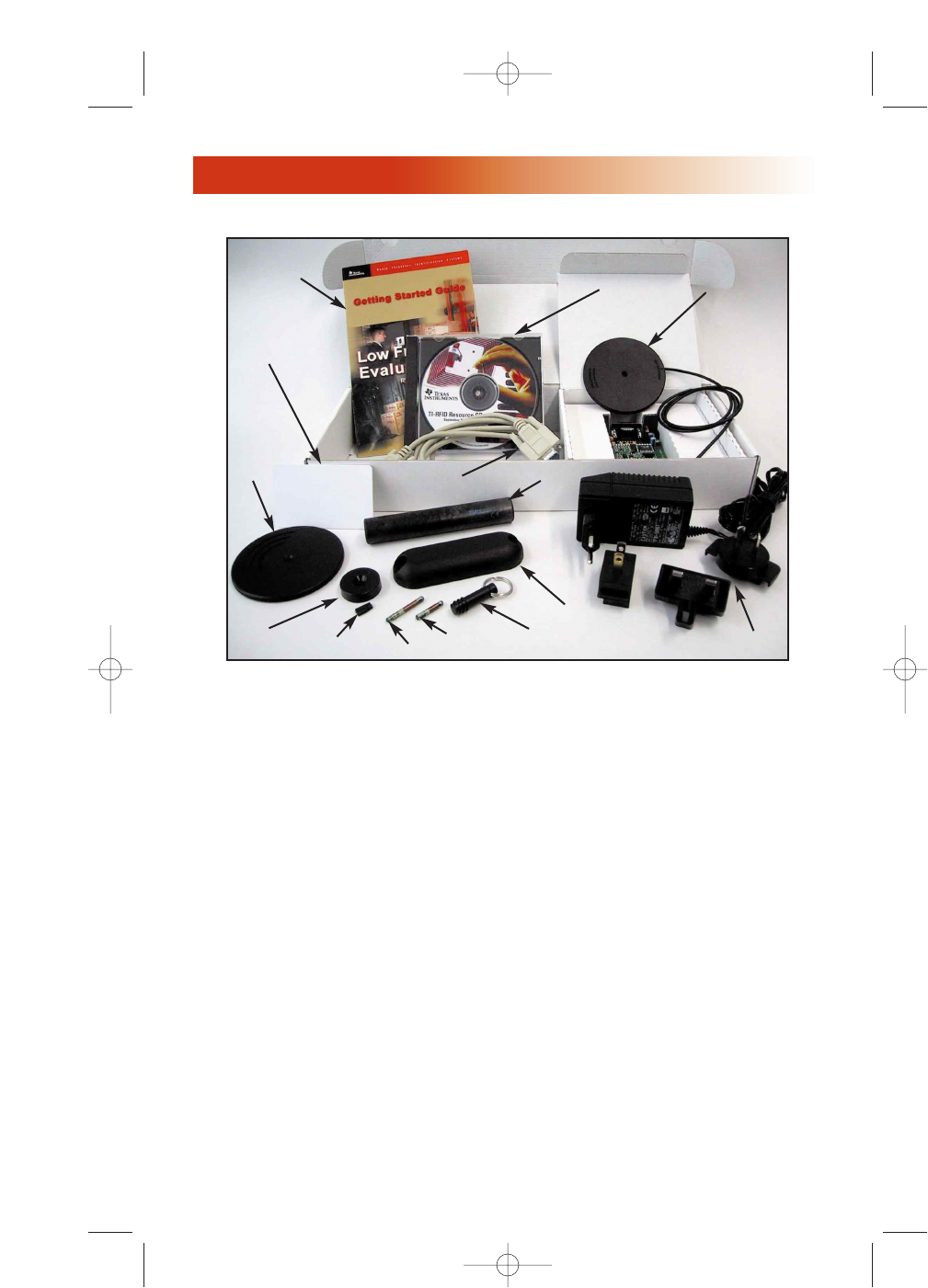
The Evaluation Kit includes the following components:
Figure 1 Low Frequency Micro Reader Evaluation Kit
Pos. Qty. Device
1. 1 32mm Glass Transponder SAMPT (RI-TRP-IR2B)
2. 1 23mm Glass Transponder R/W (RI-TRP-WRHP)
3. 1 12mm Wedge Transponder R/O (RI-TRP-R9WK)
4. 1 85mm Disk Transponder R/W (RI-TRP-W9UR)
5. 1 30mm Disk Transponder R/O (RI-TRP-R9QL)
6. 1 Mount-on-Metal Transponder R/O (RI-TRP-R9VS)
7. 1 120mm Cylindrical Transponder R/O (RI-TRP-R9TD)
8. 1 Card Transponder R/W (RI-TRP-W4FF)
9. 1 Keyfob R/O (RI-TRP-RFOB)
10. 1 S2000 Micro Reader (RI-STU-MRD1) with interface
board and antenna.
11. 1 Serial Data Cable
12. 1 Resource/Software CD
13. 1 International Power Supply (Multiple Connectors)
14. 1 Getting Started Guide
3
2. Content
32
1
7
9
4
5
10
6
8
11
13
14 12
Getting Started MicroReader 12/6/01 4:12 PM Page 6

The Micro Reader is packed in a special antistatic bag to protect it
from static charge that could cause damage.
• Handle the Micro Reader carefully and keep it in the protective
envelope until you are ready to install it.
• Whenever possible, handle the Micro Reader by its edges or frame.
4.1 Interface Cable
• Connect the serial data cable (11) with the serial interface connector
mounted on the control board of the S2000 microreader (10).
• Connect the 9-pin DB plug of the serial data cable (11) to the serial
port of a computer.
4.2 Power Supply
• Connect the output connector of the Power Supply (13) to the
reader interface board and connect the power supply to Main Power.
• The red LED on the reader should be flashing.
4.3 Software Installation
System requirements:
• 5MB available space on hard disk
• Windows 95, 98, NT, 2000
The software TIRIS Reader Manager S2_UTIL Version 1.20 can be
downloaded from the resource CD under the directory "Software" or
the website at:
http://www.ti.com/tiris/docs/products/tools.htm
S2_UTIL Version 1.2 is a Windows based software utility program
for the configuration and demonstration of our Series 2000 readers.
4. Installation
4
3. ESD Safety Information
Caution:
The input tip on the power supply must be set at positive tip
or interior output voltage. TI warranty does not cover damage
to the reader unit caused by reverse voltage polarity. Check
that the arrow on the tip of the power supply is lined up with
the (-) setting on the power supply output barrel for negative
barrel but positive tip voltage.
Getting Started MicroReader 12/6/01 4:12 PM Page 7

5
This program can be used with the following readers (controls modules):
• RI-STU-MB2A, RI-STU-MB6A (Software version 1.32, 1.4)
• RI-STU-251A, RI-STU-251B-00
• RI-STU-MRD1
Proceed with the following steps in order to install the Windows
based software to your computer:
• Create a directory c:\(…) on your computer and download the
zip-file S2_UTIL_VI_20.ZIP from the Documentation / Demo CD
• Unzip the program and copy the files in your directory c:\ (…).
• Run the reader software program by selecting S2_Util.exe.
Note:
We recommend at this time to create a short cut on your desktop in
order to have quick access.
• Click to Menu Main and open Interface.
• Switch to PORT and select the reader communication port on your
computer, default is COM 1.
• Click to Operation Mode and open Micro Reader Mode.
The red LED on the reader should be flashing.
On the Receive Window ‘Microreader Version 1.X’ will appear.
• Take one of the transponders out of the Evaluation Kit and bring it
in front of the antenna.
• Click to Line Mode.
The data of the transponder will be read continuously and shown on the
Receive Window. The Message Window will show the message "reading
successful!"
The green LED of the reader will illuminate as soon as the transponder is
within the reading range of the reader/antenna set, the yellow light will be
flickering. The intensity of the light depends on the noise level in the sur-
rounding environment.
• For a single reading test please click to Single Read while keeping
the transponder within the reading range.
The green LED of the reader will illuminate as soon as the
transponder is within the reading range of the reader/antenna set
The data (ID) of the transponder will be read once and shown on the Receive
Window. The Message Window will show the message "reading successful!".
Note:
For different reader software settings refer to the -On Line Help- files
located in the main menu of the reader program.
5. System Function Test
Getting Started MicroReader 12/6/01 4:12 PM Page 8

Manuals
For detailed specification on each item in the LF Micro Reader
Evaluation Kit please refer to the documentation provided on the CD
included with this kit, or look inside the -Document Center- on our
RFID Systems Web Site at: http://www.ti-rfid.com
1. Series 2000 Reader System, Reference Guide 11-06-21-027
Micro-reader RI-STU-MRD1
2. Series 2000 Micro Reader, Data Sheet 11-06-22-069
Micro-reader RI-STU-MRD1
The LF Micro Reader Evaluation kit comprises a RF transmission
device, and is therefore subject to national and international regula-
tions. TI has obtained approvals from approval authorities in a
number of countries and is continuing to apply for approvals in fur-
ther countries. Actual status can be advised by customer support. In
countries where approval has not been obtained, this system may be
operated only under an experimental license issued by the relevant
approval authority and must not be marketed. Before any such
device or system can be marketed, an equipment authorization must
be obtained from the relevant approval authority.
FCC Notices (U.S.A.)
The Federal Communications Commission, FCC, has imposed
approval requirements on all intentional radiator equipment. This TI
product complies with FCC rules Part 15, Subpart C, "Intentional
Radiator" Paragraph 15.207 "Conducted Limits" and 15.209 "Radiated
Emissions Limits; General Requirements". FCC certification is
required for systems and the customer is responsible for meeting
those restrictions and obtaining approval for their system from the
FCC. The intentional radiators are labeled according to the FCC with
the following label:
6
6. References
7. Regulations
Getting Started MicroReader 12/6/01 4:13 PM Page 9

The LF Micro Evaluation Kit complies with Paragraph 15.203
"Antenna Requirement," which states"[a]n intentional radiator shall
be designed to ensure that no antenna other than that furnished by
the responsible party shall be used with the device. The use of a per-
manently attached antenna or of an antenna that uses a unique
coupling to the intentional radiator shall be considered sufficient to
comply with the provisions of this section. The manufacturer may
design the unit so that the user can replace a broken antenna, but the
use of a standard antenna jack or electrical connector is prohibited. If
the customer changes the antenna, he or she should refer to section
2.803." In addition to the required regulations on intentional radia-
tors, in keeping with sections 15.21 and 15.105 for the FCC rules, TI is
informing the user of the following:
Note: This equipment has been tested and found to comply with the
limits for a Class A digital device, pursuant to Part 15 of the
FCC Rules. These limits are designed to provide reasonable
protection against harmful interference when the equipment is
operated in a commercial environment. This equipment gen-
erates, uses, and can radiate radio frequency energy and, if not
installed and used in accordance with the instruction manual,
may cause harmful interference to radio communications.
Operation of this equipment in a residential area is likely to
cause harmful interference in which case the user will be
required to correct the interference at the user’s expense.
Notice: Modifications to this device will void the authorization
granted under Federal Communications Commission Rules permit-
ting the operation of this device. If modifications to the product are
made, the customer is responsible for obtaining FCC approval. For
more information regarding the FCC regulations please refer to the
following websites:
7
FCC ID: A92LFMICROEVALKIT
This device complies with Part 15 of the FCC Rules. Operation is
subject to the following two conditions: (1) this device may not
cause harmful interference, and (2) this device must accept any
interference received, including interference that may cause
undesired operation.
Getting Started MicroReader 12/6/01 4:13 PM Page 10

8
http://www.access.gpo.gov/nara/cfr/waisidx_98/47cfr15_98.html
http://www.fcc.gov/
CE Conformity (Europe)
A CE Declaration of Conformity is available for the Reader
RI-STU-MRD1 at TI*RFID Sales Offices.
The equipment complies with the essential requirements of the
Telecommunication Terminal Equipment Act (FTEG) and the R&TTE
Directive 99/5/EC when used for its intended purpose.
Any device or system incorporating this module in any other than
the originally tested configuration needs to be verified against the
requirements of the Telecommunication Terminal Equipment Act
(FTEG) and the R&TTE Directive 99/5/EC. A separate Declaration of
Conformity must be issued by the system integrator or user of such a
system prior to marketing it and operating it in the European
Community.
It is the responsibility of the system integrators to get their complete
system tested and obtain approvals from the appropriate local
authorities before operating or selling the system.
Getting Started MicroReader 12/6/01 4:13 PM Page 11
© Copyright Texas Instruments. 2001
All rights reserved.
Windows is a registered trademark of Microsoft Corporation in the United States
and/or other counties.
9
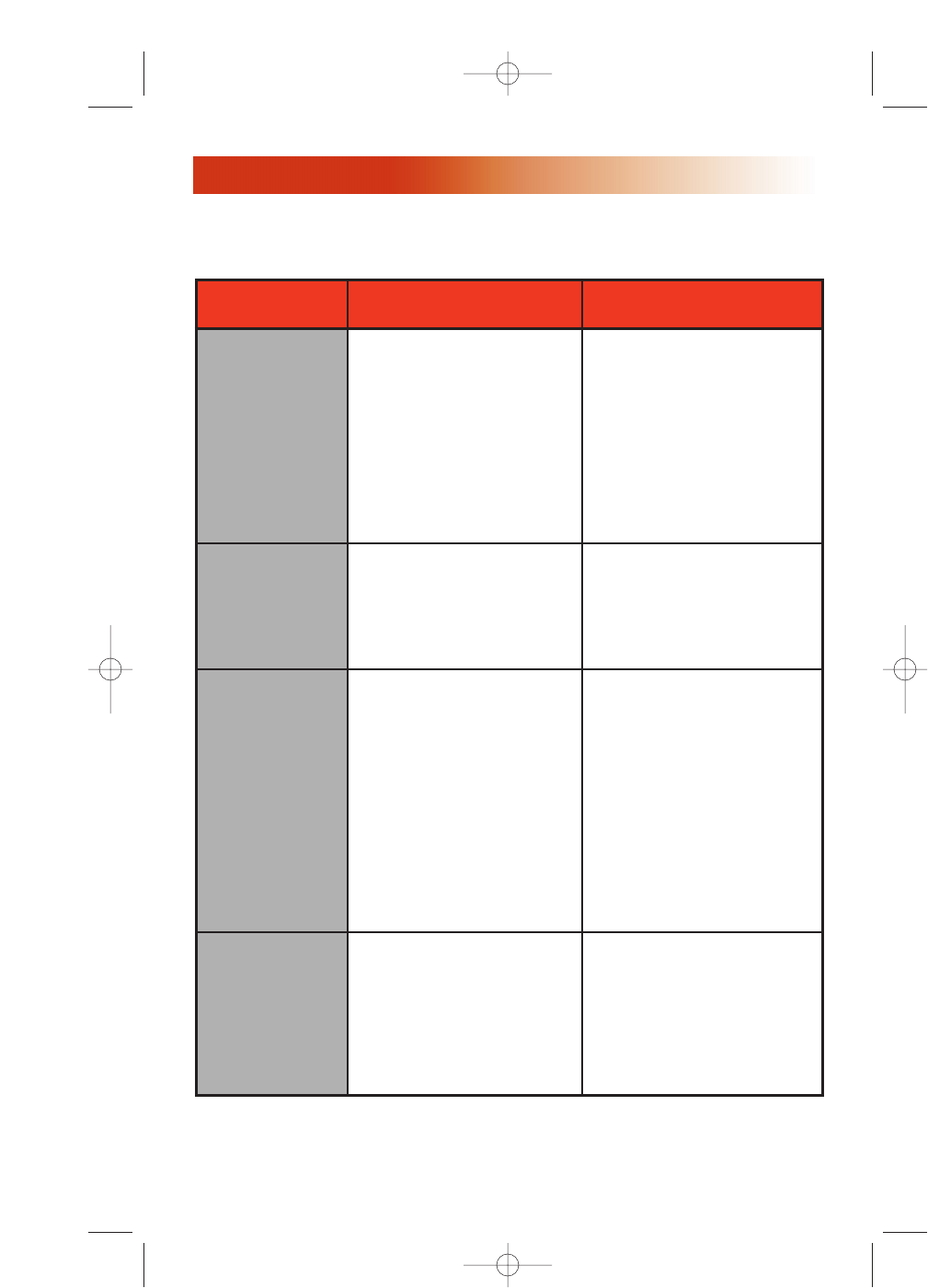
8. Troubleshooting
- Software does not recog-
nize reader
- No read / write function
- Intermittent read / write
function of the reader
• Ensure that
- all cables are connected
properly.
- interface port at PC is set
properly.
- No reader function
(Red LED does not flash)
• Ensure that
- all plugs are connected
- main power is connected
properly on power supply.
• Plugging the power sup-
ply into a power strip can
result in power spikes that
cause the unit not to
function properly.
- No read / write function • Move transponder closer
to antenna and try
different orientations of
the transponder.
• Replace transponder and
try once again.
Item Problem Verification
Power
Communication
Antenna
Transponder
For customer and technical support email to rfidsupport@ti.com or
telephone at +972-575-7518 or Toll Free for US at 1-888-937-6536.
- Low read / write range
- Intermittent read / write
function
• Ensure that the wire ends
of the antenna are
fastened to the S2000
Micro Reader IF Board.
• Change the environment
around the antenna and
reader to check for possi-
ble interference. Typically,
interference can emit from
computer video displays
and metal beneath surfaces.
Getting Started MicroReader 12/6/01 4:13 PM Page 12