Texas Instruments LMX9838 Bluetooth Serial Port Module User Manual LMX9838DONGLE Hardware User Guide
Texas Instruments Inc. Bluetooth Serial Port Module LMX9838DONGLE Hardware User Guide
Contents
- 1. User Manual
- 2. Manual
- 3. Users Manual
Manual
© 2006 National Semiconductor Corporation www.national.com
LMX9838DONGLE Hardware User Guide
1.0 Scope
National Semiconductor LMX9838 Bluetooth™ serial don-
gle reference design kit is a plug and play serial adapter for
serial cable replacement applications and more. It is able to
support more profiles than just the Serial Port Profile
(including audio support with external codec boards). By
using the enclosed Simply Blue Commander software, it
allows user to develop their own SW applications easily
given the built in interpreter for HEX commands. SBSmart
is a higher level application tool that provides buttons with
the built in commands to easily set up or demonstrate dif-
ferent profile support using the Simply Blue SPP package.
2.0 General Description
2.1 REFERENCE DESIGN KIT CONTENTS
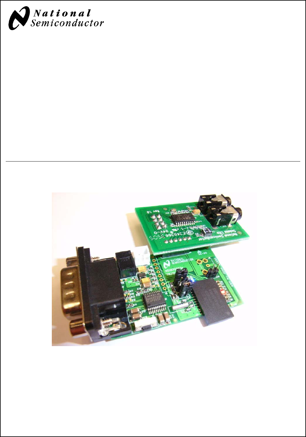
■LMX9838 Bluetooth serial adapter reference board
■USB Dongle and application software stack
■Null modem cable
■Sedona Lite board (Audio CODEC Board)
■110V to 240V AC to 5V DC power adapter and pigtail
■CDROM with design documents and Simply Blue soft-
ware Application tools.
2.2 LMX9838 BLUETOOTH SERIAL
ADAPTER REFERENCE BOARD
Figure 1. Reference Board and Sedona Lite Board
Bluetooth is a trademark of Bluetooth SIG, Inc. and is used under license by National Semiconductor.
September 2006
Revision 0.2
LMX9838DONGLE Hardware User Guide
www.national.com 2
LMX9838DONGLE Hardware User Guide
3.0 Requirement and Setup
3.1 BASIC REQUIREMENT
■X86 PC with serial port.
■One of the following operating system is required.
— Windows 2000
— Windows XP
3.2 APPLICATION SOFTWARE
3.2.1 Simply Blue Commander
Application command oriented tool to generate commands
and watch events in the Simply Blue Command interface
window. Reference the Simply Blue Commander User
Guide document for details.
3.2.2 SBSmart
Easy to use Windows based tool to demonstrate additional
profile support of the Simply Blue functionality. Reference
the SBSmart User Guide for additional details.
3.2.3 Patch Programming
LMX9838 allows for patch programming for firmware
update if necessary. Reference the LMX9838 SW User
Guide document for details. Can also be done with the
Simply Blue Commander tool.
4.0 Functional Description
4.1 POWER SUPPLY
■DC Power Jack (6V max)
■Battery Holder (6V max)
4.2 MAIN SYSTEM
■Reset button for manual Reset
■Jumper option for Baud rate selection
4.3 UART INTERFACE
DB9 connector for RS232 standard PC interface using On-
board level shifter IC for handling LMX9838 module’s 3.3V
UART interface.
4.4 ADVANCE AUDIO INTERFACE
■Support Audio applications
■PCM codec interface (support linear and A-law)
■PCM Master or Slave operation (SW configurable)
■Direct connection to Sedona Lite Board (A-law only)
5.0 Design Consideration
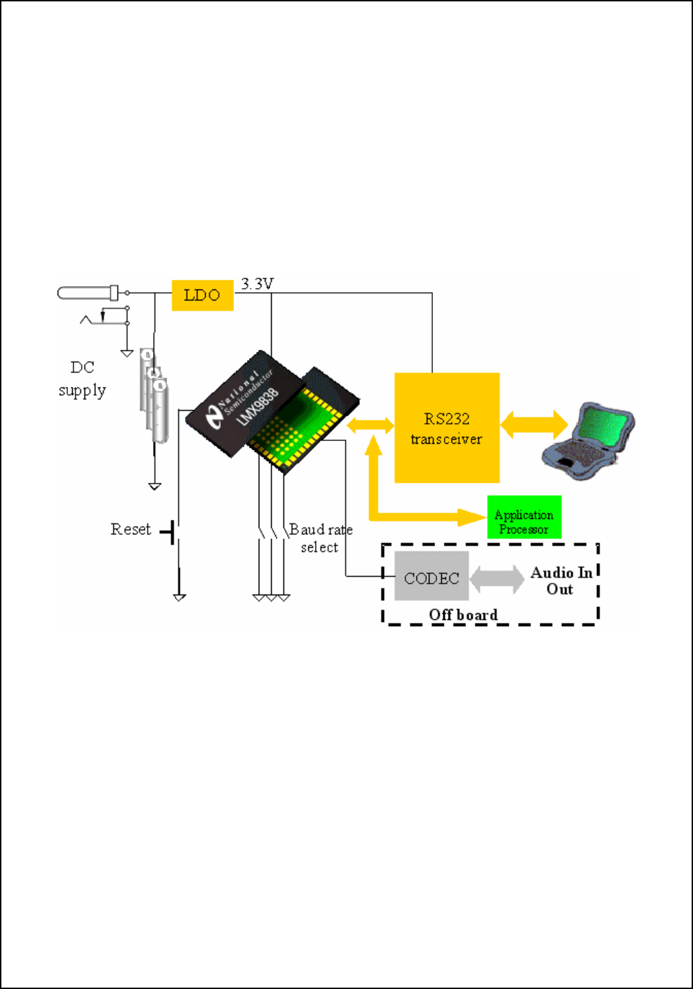
5.1 POWER MANAGEMENT
■3.3V output single LDO is used to provide power for
RS232 interface chip and Digital portion of the LMX9838.
Figure 2. System Block Diagram
3 www.national.com
LMX9838DONGLE Hardware User Guide
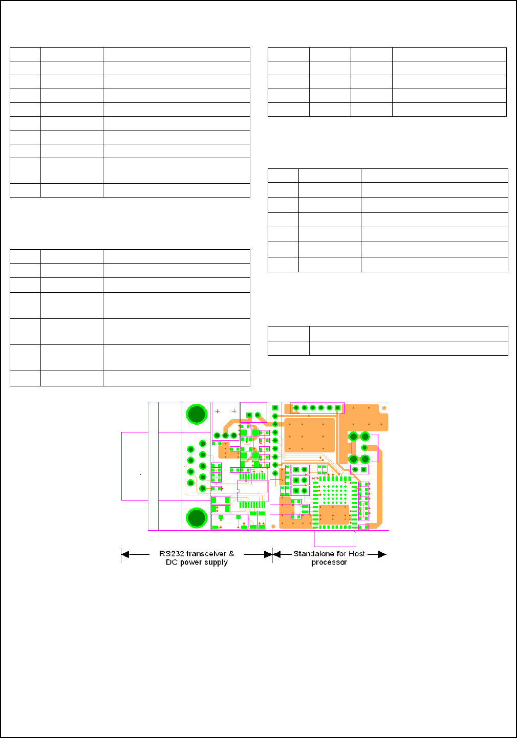
6.0 Layout Consideration
The LMX9838 reference design is split into 2 sections, one
section is RS232 transceiver circuit for PC connection,
another section is LMX9838 main circuit for Host proces-
sor. (Figure 3)
6.1 PCB REQUIREMENT
■2 layers PCB required
■1 mm overall thickness
6.2 LAYERS CLASSIFICATION
■Top layer is the components and main signals layer
■Bottom layer is interface signals and ground plane
■RF circuit requirement
■Large ground plane with ground via’s is must for good
RF performance
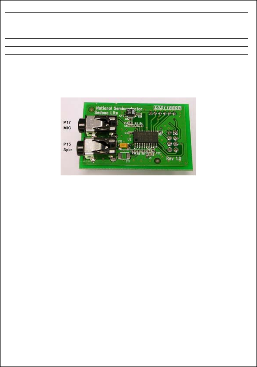
7.0 AUDIO CODEC Board
Sedona Lite Board contains an audio codec and two phone
jacks. This board can be used in conjuction with
LMX9838DONGLE to realize audio transmission and
reception. See Table9
8.0 Board components and Pin As-
signments
A summary of the configuration and selection jumpers is
provided in the tables that follow. Reference both the sche-
matic and PCB layout (included on the CD in the kit)
Table 1 Major Components List
Device Description
U1 National LMX9838 Serial Port Module - Refer-
ence the device datasheet.
U3 National LP3985 Low-Dropout Voltage Regula-
tor
U2 Maxim MAX3225 1 Mbps High Speed UART
Driver
Table 2 Connectors Summary
Connector Description Details
J7 Battery Connector
2mm pitch
Maximum input volt-
age is 6V
J6 DC jack Same as above
J8 DP9 serial connec-
tor (male)
See Table 5
J5 External processor
interface
See Table 6
J4 Advance Audio
interface
See Table 7
Table 3 Jumper and Test Point Summary
Jumper /
Test Point Description Details
J1, J2 and
J3
Clock & UART set-
ting jumper
See Table 8
Table 4 Switch and LEDs
Switch/LED Description
S1 Reset button
D1 Operation Status
D2 Data Traffic (TX/RX)
Table 5 J8 DP9 (male) Pin Assignments
Pin # Signal name Description
1 NC No connection
2 RxD Receive Data (input)
3 TxD Transmit Data (output)
4 NC No connection
5 GND Ground
6 NC No connection
7 RTS Ready to send (output)
8 CTS Clear to send (input)
9 NC No connection
www.national.com 4
LMX9838DONGLE Hardware User Guide
Table 6 J5 External Processor Interface
Pin # Signal name Description
1 POWER_D# ON/OFF control of LMX9838
2 VCC LDO output (3.3V)
3 GND Ground
4 TXD Transmit Data (output)
5 CTS# Clear to send (input)
6 RXD Receive Data (input)
7 RTS# Ready to send (output)
8 VCC_CORE
_IN
1.8V voltage regulator input/out-
put
9 RESET# Reset (input)
Table 7 J4 Advance Audio Interface
Pin # Signal name Description
1VCC LDO output (3.3V)
2SCLK Advanced Audio Interface Clock
3STD Advanced Audio Interface
Transmit Data
4SFS Advanced Audio Interface Frame
Synchronization
5SRD Advanced Audio Interface
Receive Data
6GND Ground
Table 8 UART interface setting
J2 J3 J1 UART baud rate
Short Short Short 921600bps
Short Open Short 115200bps(default)
Open Short Short 9600bps
Open Open Short NVS (Default 9600bps)
Table 9 J4 (Audio CODEC Board)
Pin # Signal name Description
1Vcc 3.3V Input
2SCLK PCM Clock
3STD PCM Input Data
4SFS PCM Frame Synchronization
5SRD PCM Output Data
6GND Ground
Table 10 Audio Connection
P17 For PC Microphone
P15 For PC Headphone
Figure 3. Top view of Reference board
www.national.com 5
LMX9838DONGLE Hardware User Guide
9.0 Bill of materials (Reference Board)
10.0 Bill of Materials (Sedona Lite Board)
Item Name Description Vendor Part Number
C5,C6 Capacitor 22p 0603 C0G 50V MuRata GRM39C0G220J50
C1,C3,C8,
C10
Capacitor 100n 0603 Y5V 50V MuRata GRM39Y5V104Z50
C2,C4,C7 Capacitor 2u2F 0603 Y5V 10V MuRata GRM39Y5V225Z10
C9 Capacitor 100p 0603 C0G 50V MuRata GRM39C0G101J50
C11,C12 TANT CAP 1uF 16V SIZE A Any
C13,C14,C15,
C16,C17
Capacitor 1uF 1206 X7R 25V MuRata GRM42-6X7R105K25
C19 Capacitor 1uF 0603 Y5V 10V MuRata GRM39Y5V105Z10
J7 Battery holder (2mm pitch) Any
S1 TACK SWITCH TS-1135HS RAINBOW
Y1 Tuning fork crystal 32.768KHz Any
J6 DC POWER JACK Morning star limited DC-015
D1 Red Color LED 0603 Size Any
D2 Blue Color LED 0603 Size Any
J8 DB9 (male) serial connector Any
J4 2mm Socket (6 poles) Any
U1 Bluetooth SPP Micro Module National Semiconductor LMX9838SM
U3 Low Dropout Regulator National Semiconductor LP3985IM5X-3.3
U2 High Speed RS232 Transceivers Maxim MAX3225EEAP+
R1,R2,R3 Resistor 0603 Size, 1K Any
R11,R12 Resistor 0603 Size, 10K Any
R6,R7,R8,R9,
R13,R14,R17
Resistor 0603 Size, 0R Any
R4,R5 Resistor 0603 Size, 330R Any
J3,J10 2mm header Any
J1,J2 2mm header (with jumper) Any
Item Name Description Vendor Part Number
C3,C4,C5,C6 Capacitor 100nF Any Ceramic cap
C6 Capacitor 1uF Any Ceramic cap
C12 TANT CAP 10uF, 10V Any
C40 TANT CAP 47uF, 6.3V Any
C11 Not mount
J1 2mm socket (6 poles) Any
J2 2.54mm socket (2 x 4 poles) Any
P15 Socket for speaker (mono) Morning Star MSJ-1537
P17 Socket for microphone (mono) Morning Star MSJ-1537
R10 Resistor 0402 Size, 10R Any
www.national.com 6
LMX9838DONGLE Hardware User Guide
11.0 References
■LMX9838 Bluetooth Serial Port Module data sheet
■LMX9838 Bluetooth Serial Port Module - Software Users
Guide
■SBSmart user guide
R13,R14 Resistor 0402 Size, 1K Any
R5,R22 Resistor 0402 Size, 4.7K Any
R3 Resistor 0402 Size, 10K Any
R4,R8,R9 Resistor 0402 Size, 47K Any
U2 Single Rail Codec OKI MSM7717-01MS-K
Item Name Description Vendor Part Number
Figure 4. Sedona Board

LMX9838DONGLE Designer Guide
National does not assume any responsibility for use of any circuitry described, no circuit patent licenses are implied and National reserves the right at any time without notice to change said circuitry and specifications.
LIFE SUPPORT POLICY
NATIONAL’S PRODUCTS ARE NOT AUTHORIZED FOR USE AS CRITICAL COMPONENTS IN LIFE SUPPORT
DEVICES OR SYSTEMS WITHOUT THE EXPRESS WRITTEN APPROVAL OF THE PRESIDENT AND GENERAL
COUNSEL OF NATIONAL SEMICONDUCTOR CORPORATION. As used herein:
1. Life support devices or systems are devices or systems which,
(a) are intended for surgical implant into the body, or (b) support
or sustain life, and whose failure to perform, when properly used
in accordance with instructions for use provided in the labeling,
can be reasonably expected to result in a significant injury to the
user.
2. A critical component is any component of a life support device
or system whose failure to perform can be reasonably expected
to cause the failure of the life support device or system, or to af-
fect its safety or effectiveness.
National Semiconductor
Corporation
Tel: 1-800-272-9959
Fax: 1-800-737-7018
Email: support@nsc.com
National Semiconductor
Europe
Fax: +49 (0) 180-530 85 86
Email: europe.support@nsc.com
Deutsch Tel: +49 (0) 69 9508 6208
English Tel: +44 (0) 870 24 0 2171
Francais Tel: +33 (0) 1 41 91 8790
National Semiconductor
Japan Ltd.
Tel: 81-3-5639-7560
Fax: 81-3-5639-7507
www.national.com
National Semiconductor
Asia Pacific
Customer Response Group
Tel: 65-254-4466
Fax: 65-250-4466
Email: ap.support@nsc.com
BANNED SUBSTANCE COMPLIANCE
National Semiconductor certifies that the products and packing materials meet the provisions of the Customer Products Stewardship
Specification (CSP-9-111C2) and the Banned Substances and Materials of Interest Specification (CSP-9-111S2) and contain no “Banned
Substances” as defined in CSP-9-111S2.
Leadfree products are RoHS compliant.