Texas Instruments LMX9838 Bluetooth Transceiver User Manual
Texas Instruments Inc. Bluetooth Transceiver Users Manual
UserManual.wiki
>
Texas Instruments
>
LMX9838 User Manual
>
Users Manual
Contents
1.
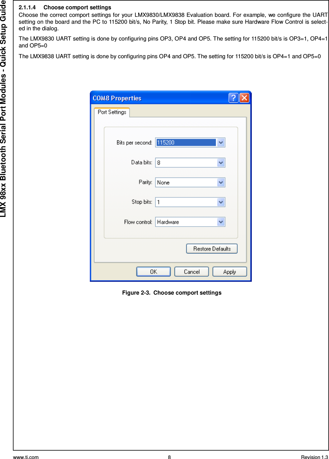
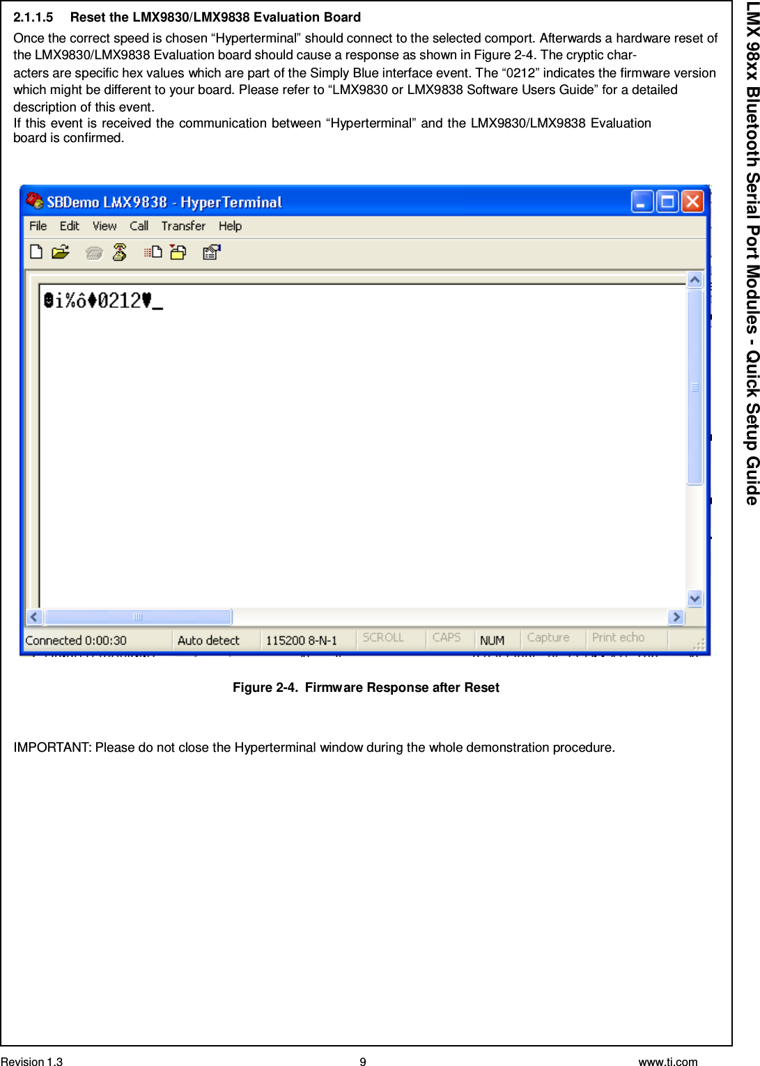
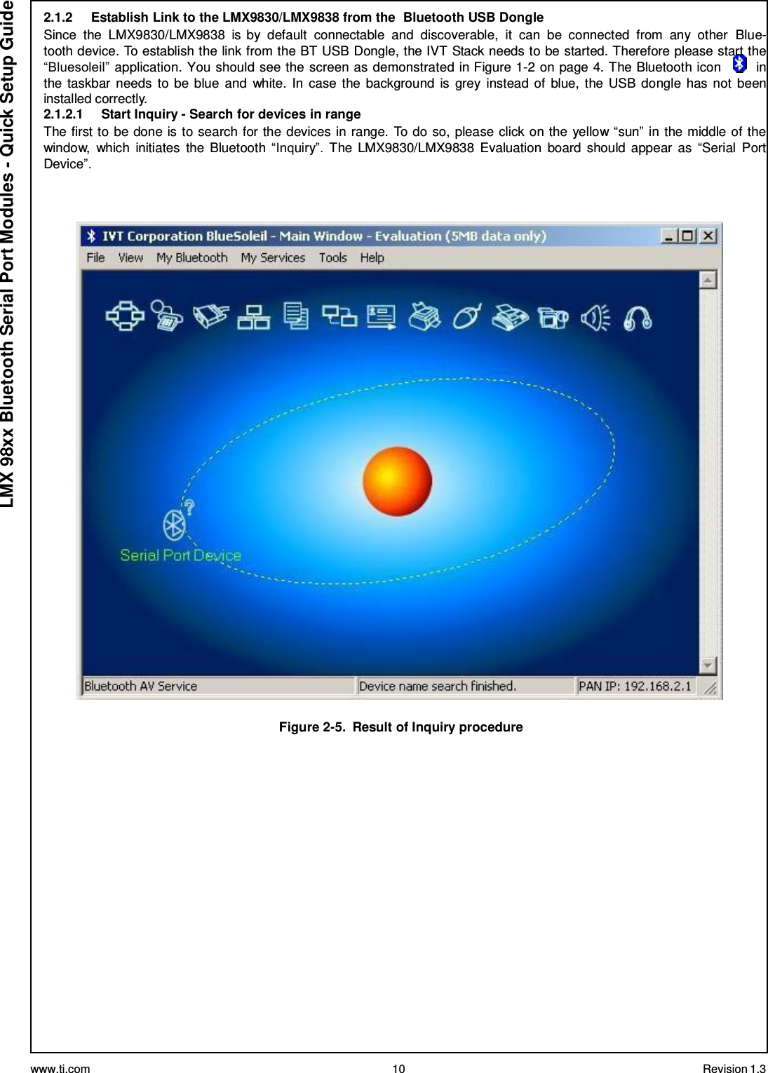
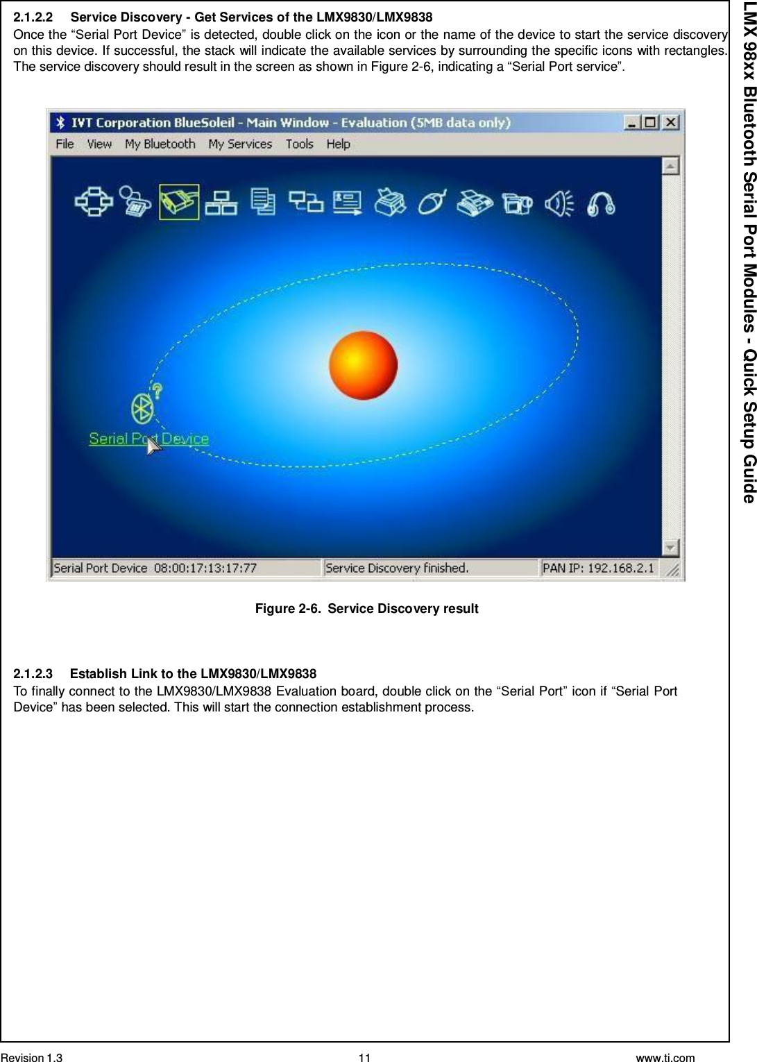
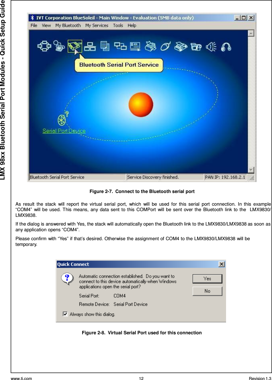
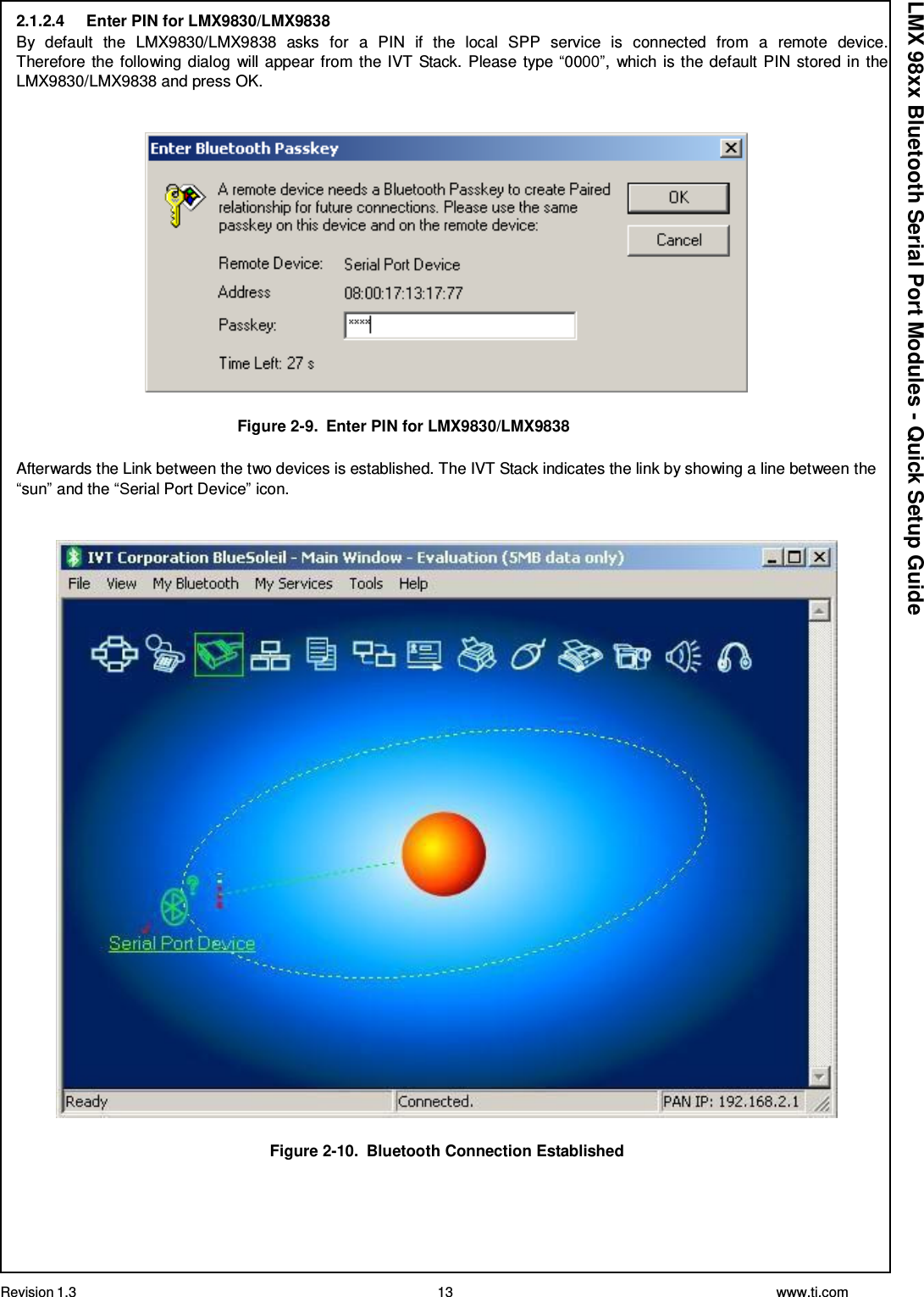
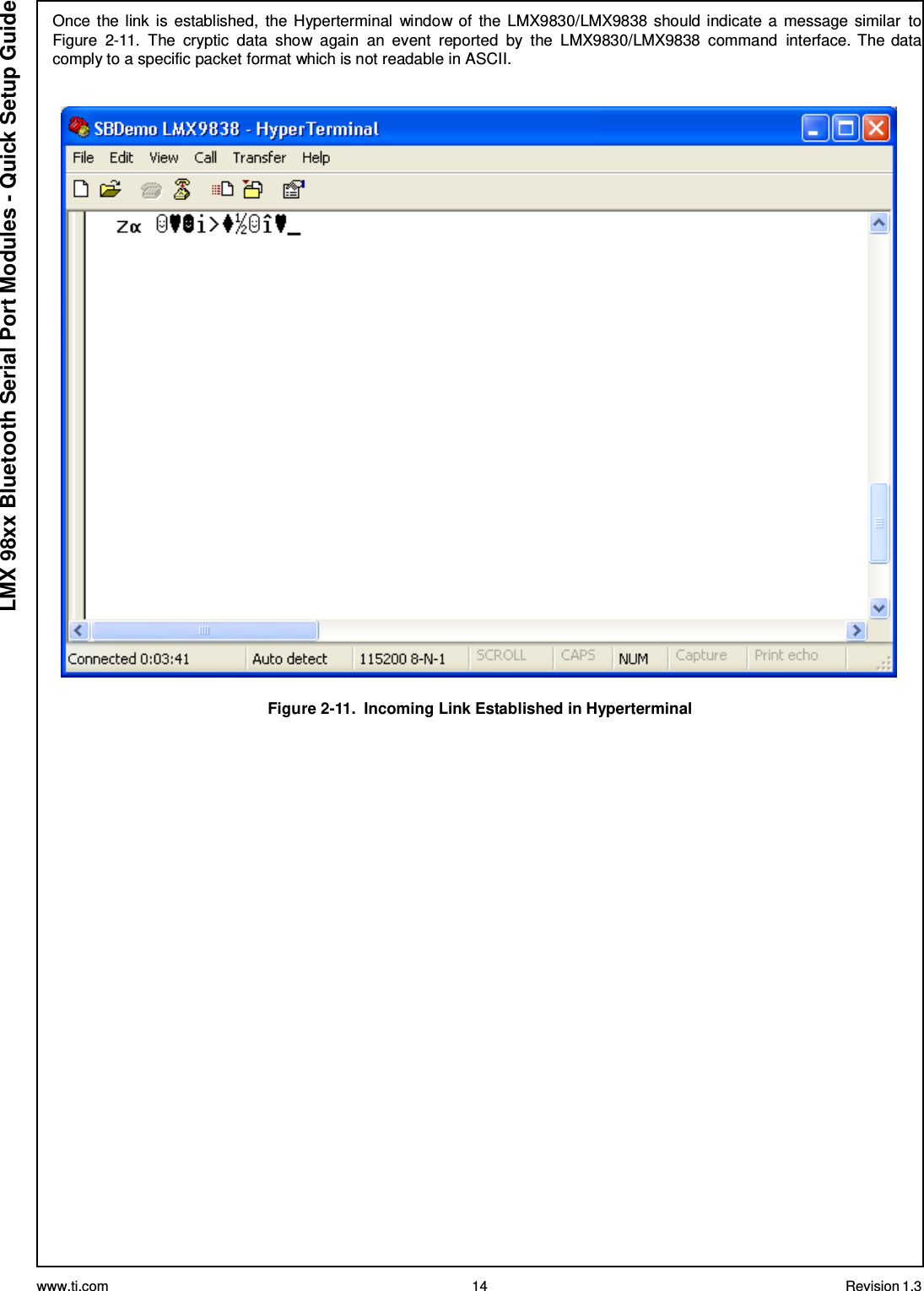
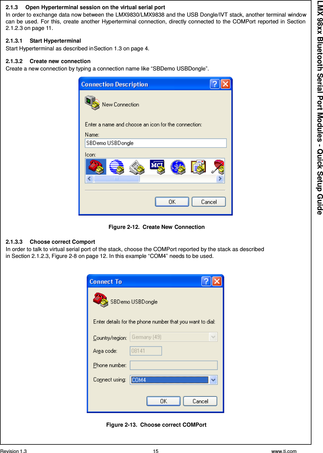
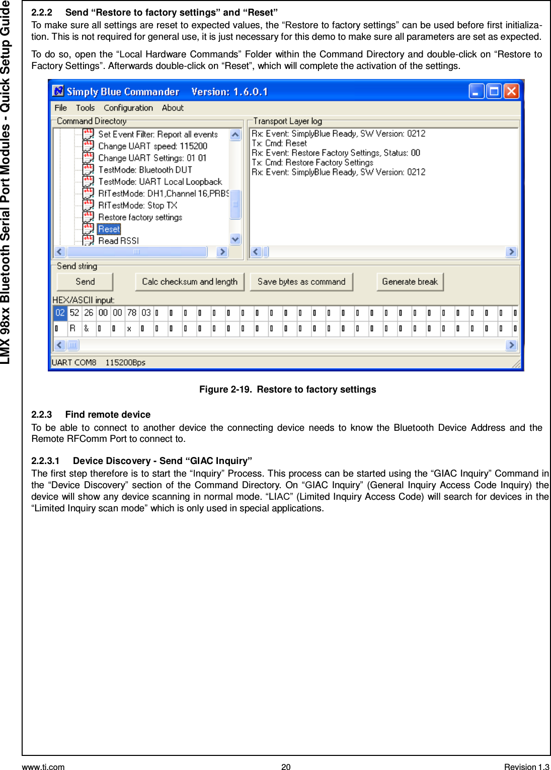
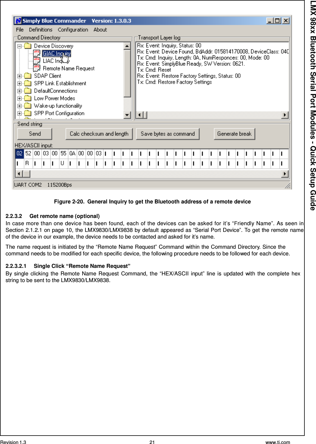
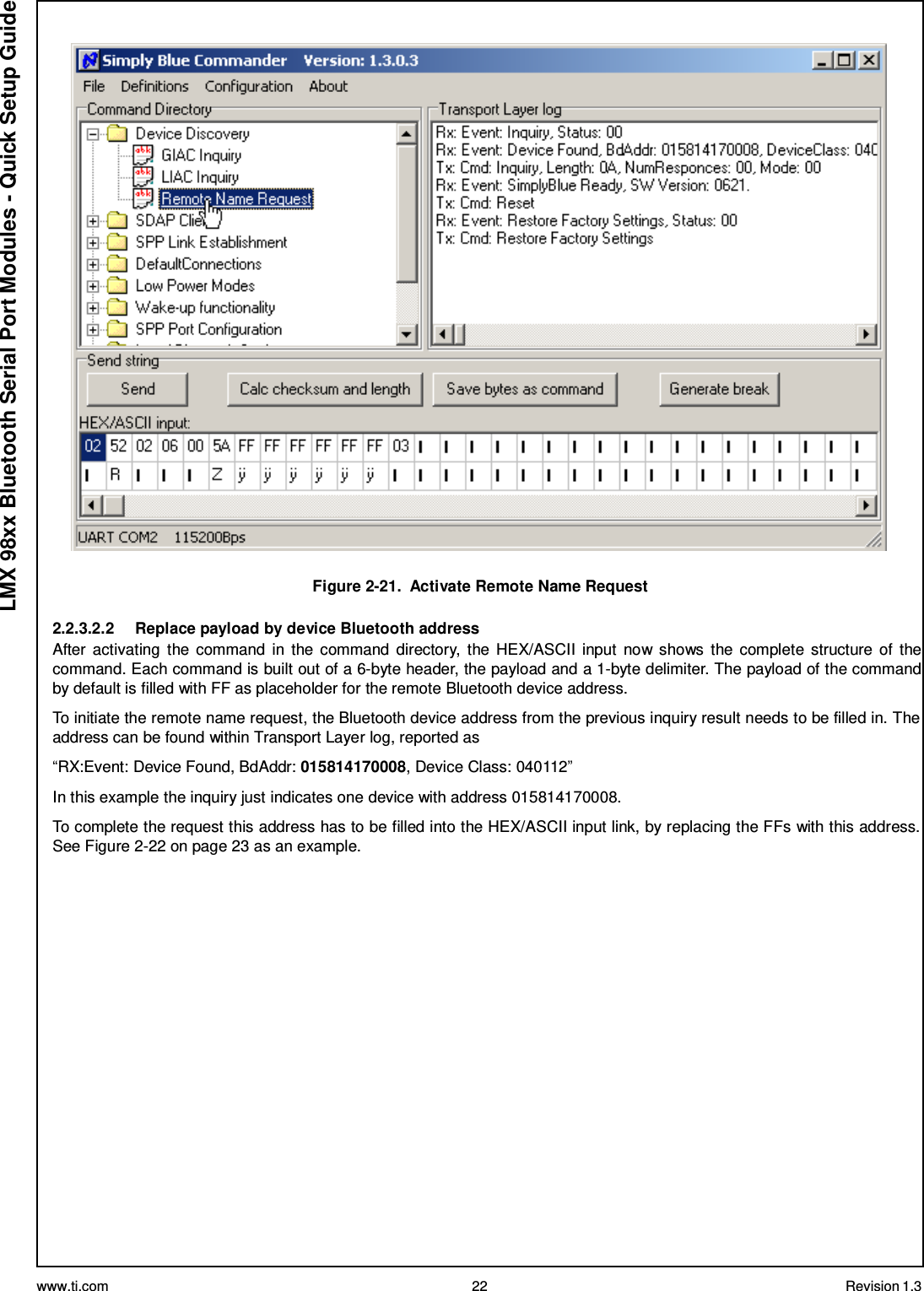
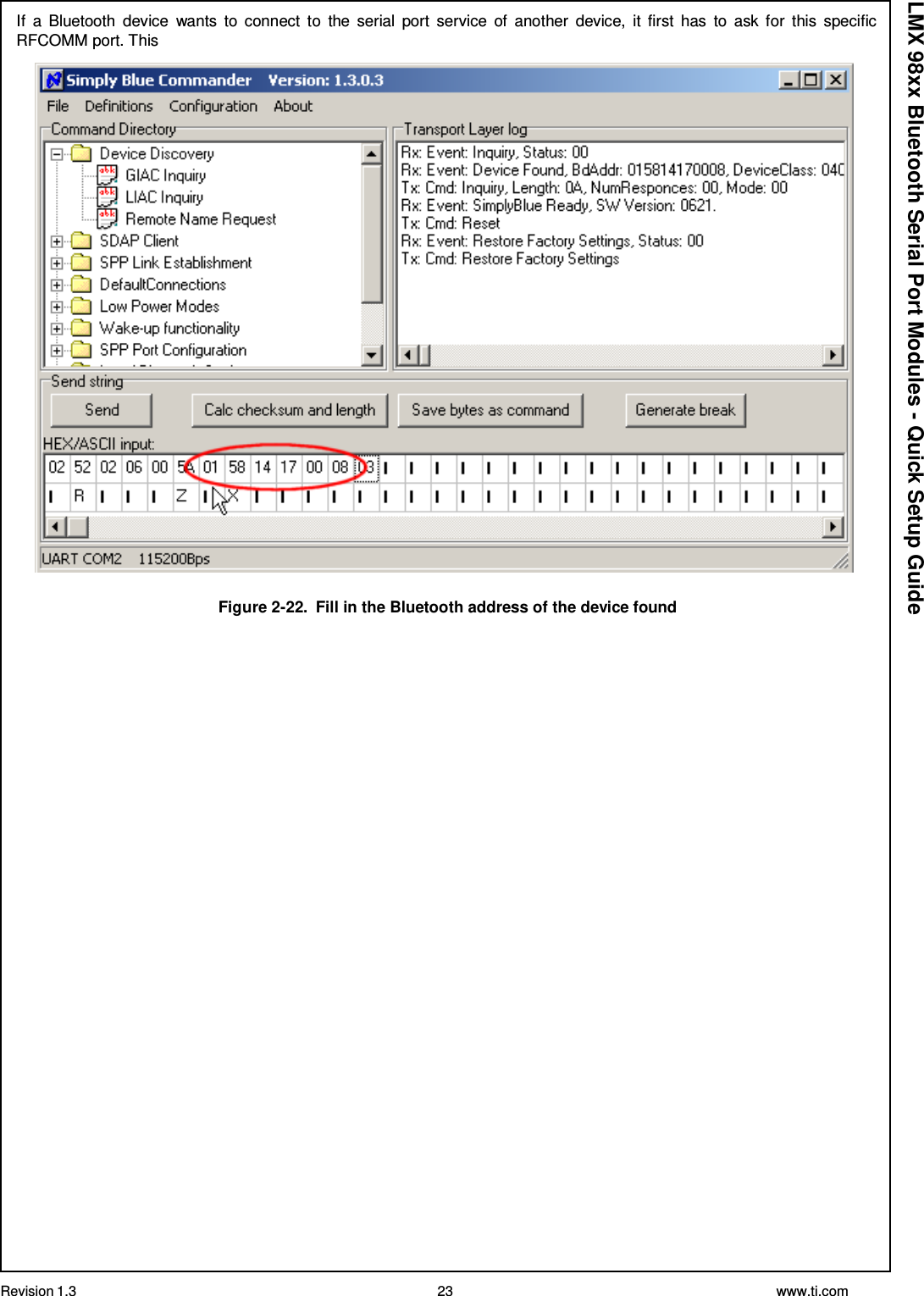
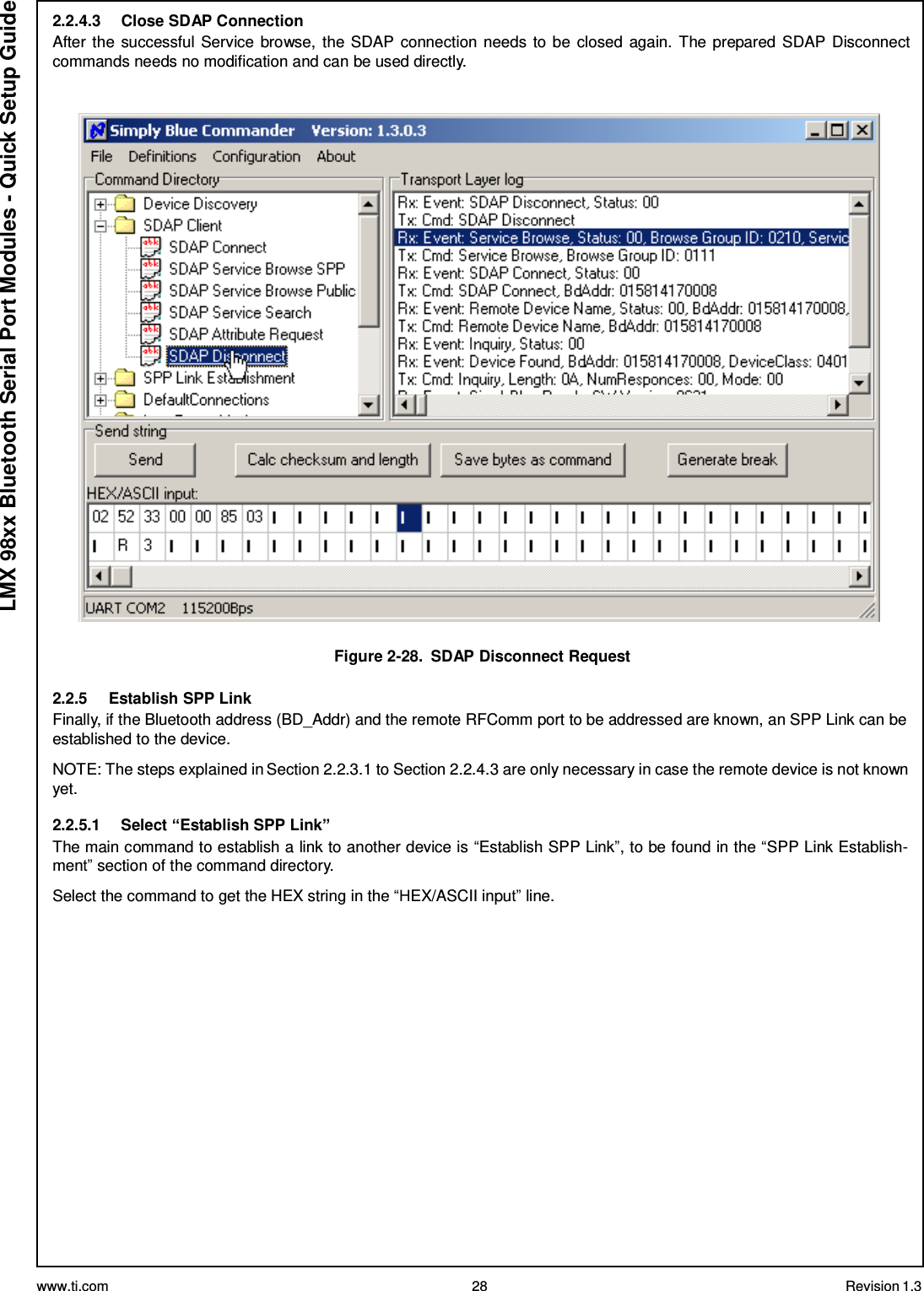
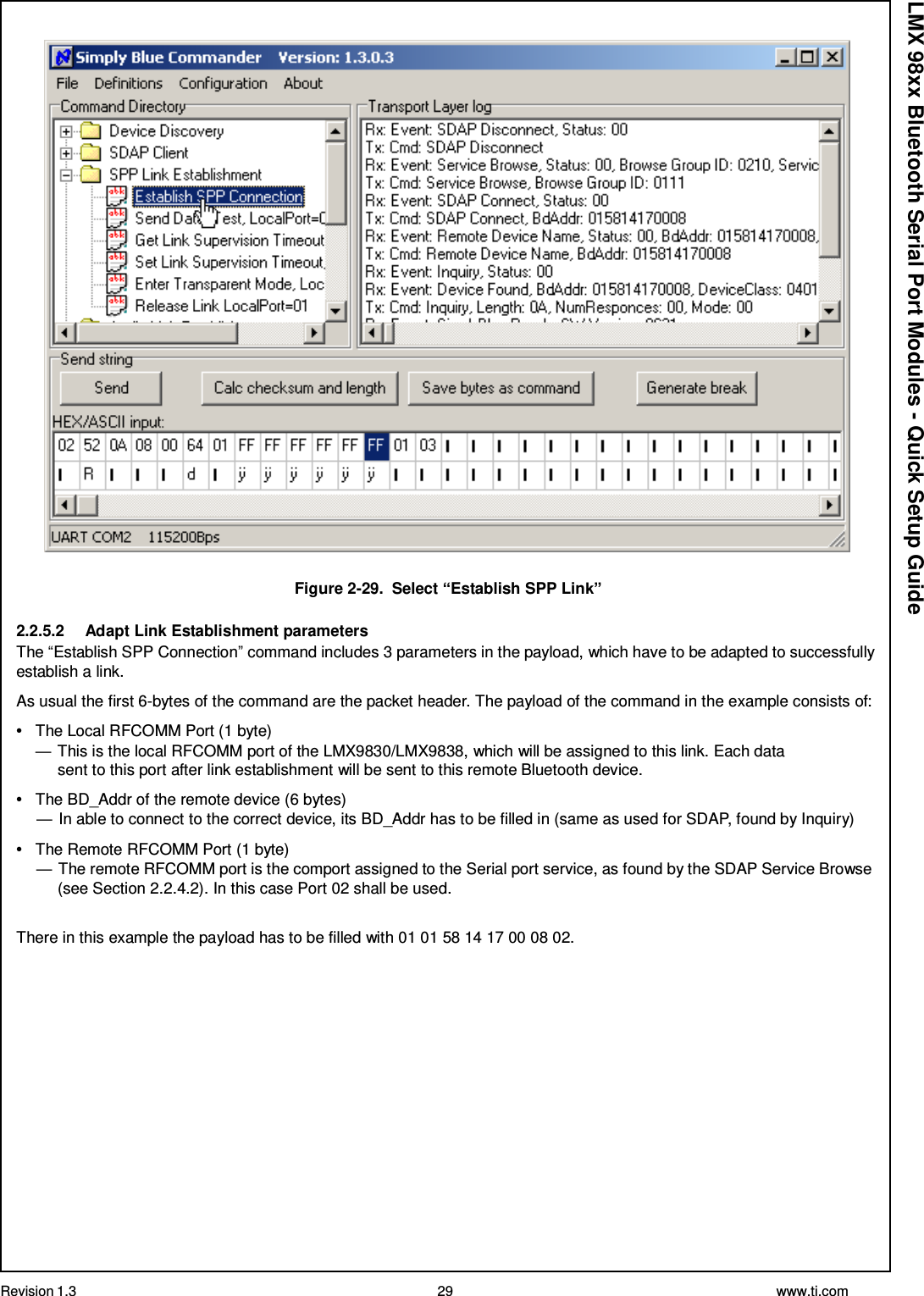
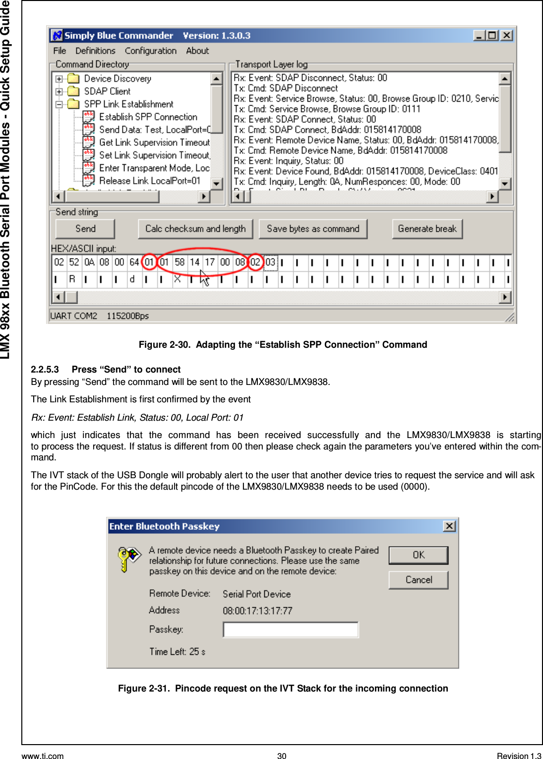
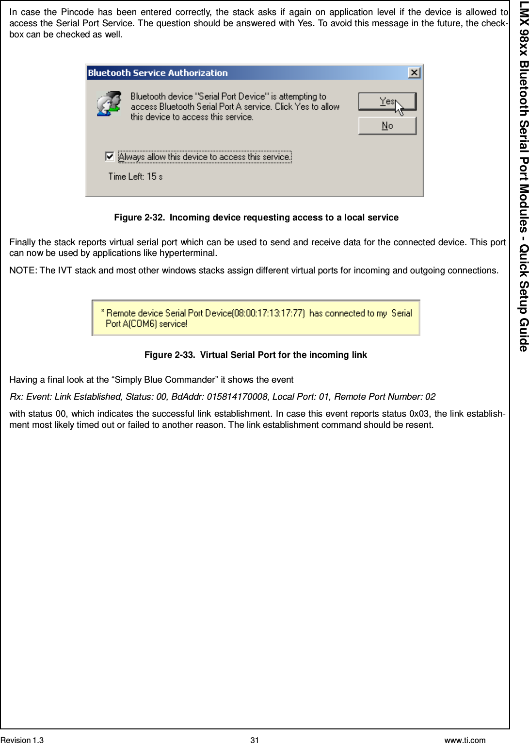
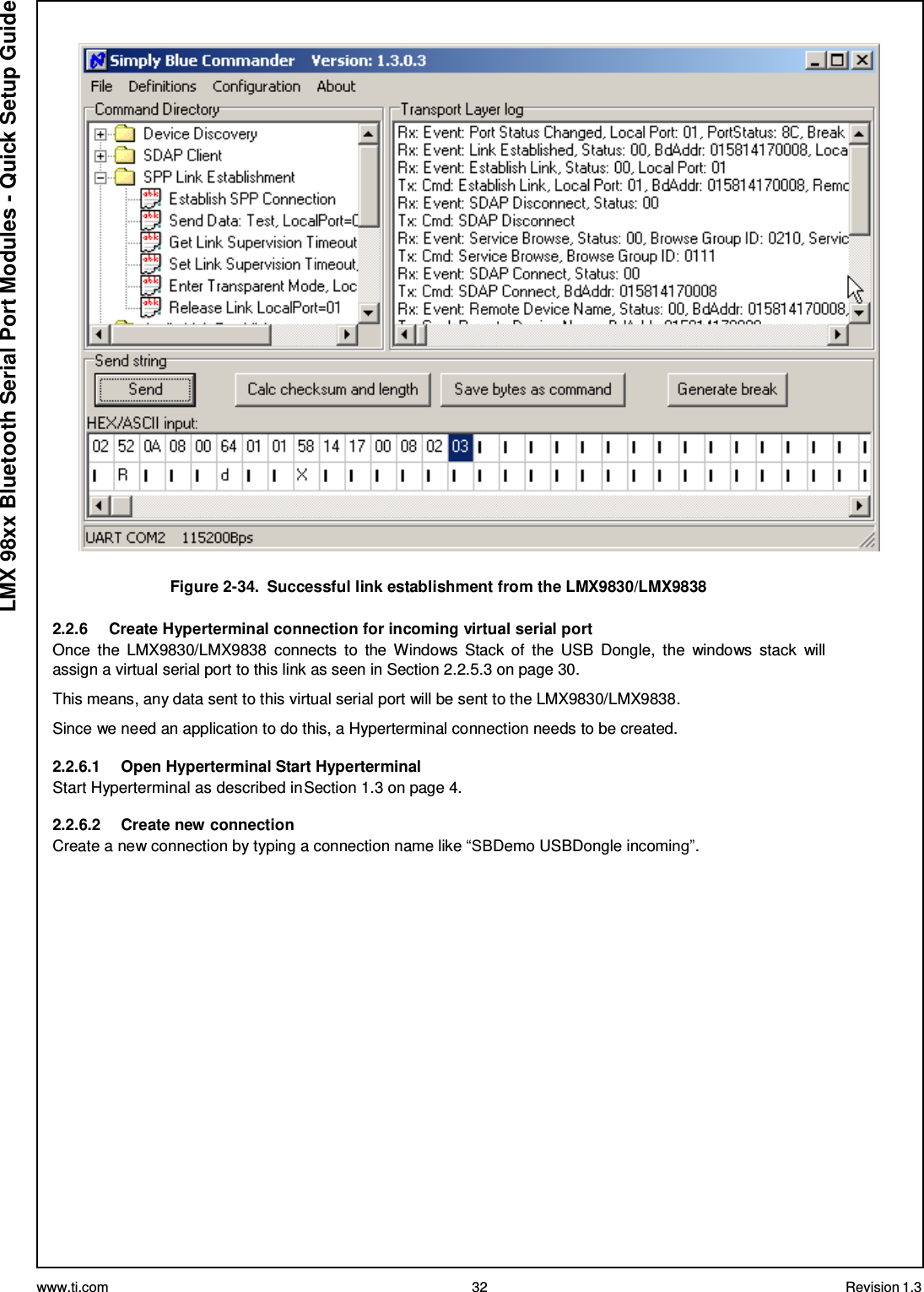
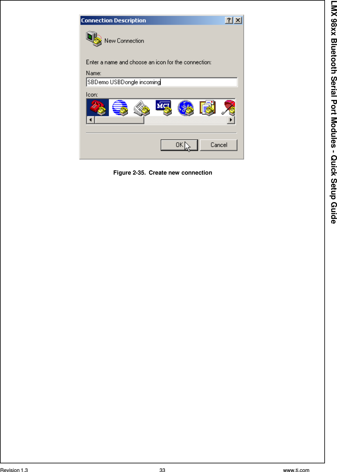
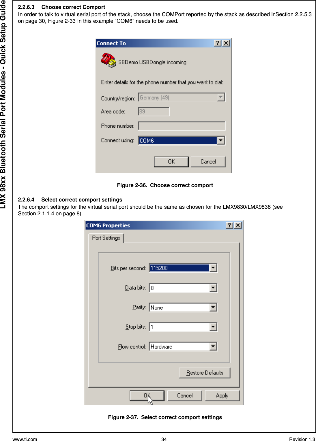
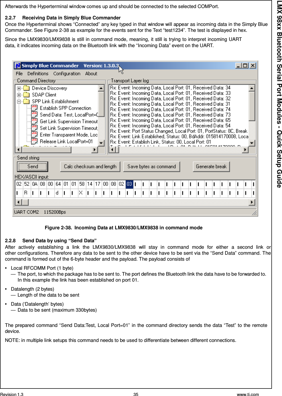
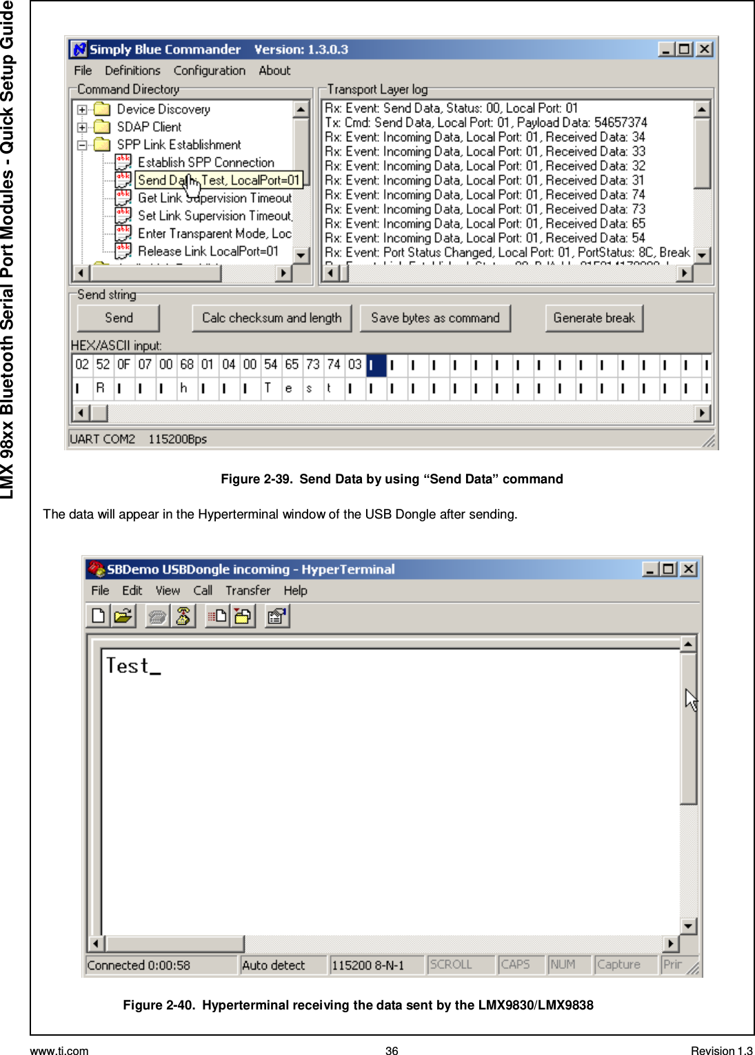
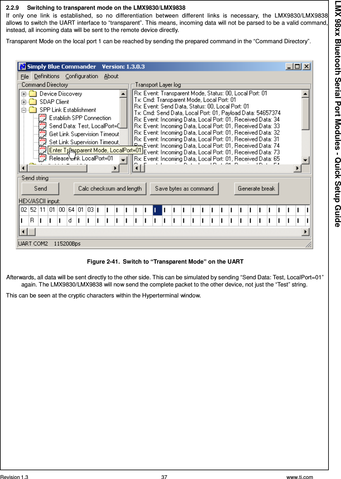
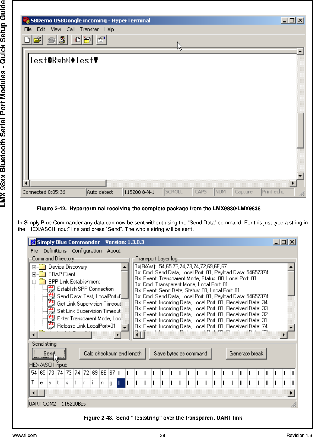
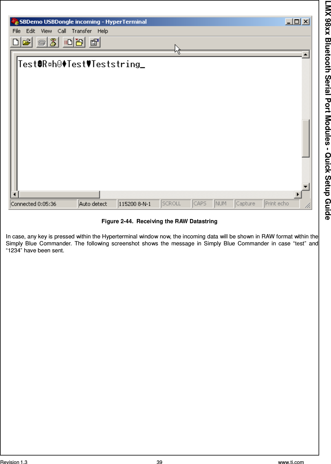
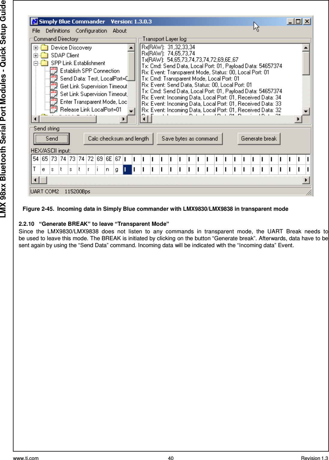
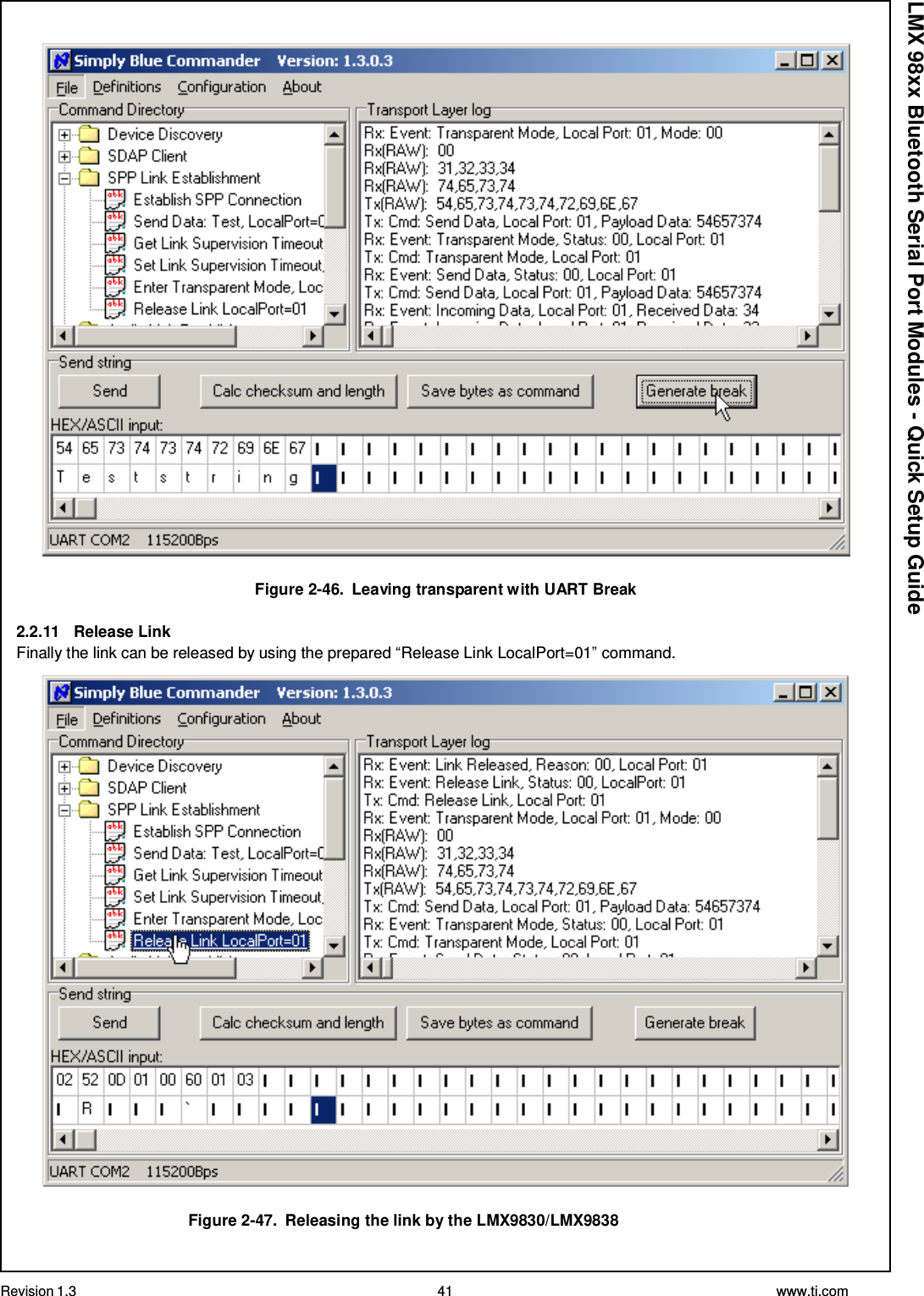
User Manual
2.
Manual
3.
Users Manual
Users Manual
Navigation menu
Upload a User Manual
Namespaces
Wiki Guide
HTML
PDF
Info
Views
User Manual
Discussion / Help
Navigation