Texas Instruments RU1001A User Manual Texas Instruments
Texas Instruments Inc Texas Instruments
Added requested info

1
Draft Document
UHF Reader System Series 7000
Reader Module RI-RU1-001A-XX
Reference Guide
Draft Document August 2001
FCC ID: A92RU1001A

August 2001 Series 7000 Reader Reference Guide
2
FCC ID: A92RU1001A
First Edition - August 2001
This is the first edition of this manual. It describes the operation of the Series 7000
UHF Reader.
It contains a description of the following reader module:
Reader Module: RI-RU1-001A-00
Texas Instruments (TI) reserves the right to make changes to its products or services or
to discontinue any product or service at any time without notice. TI provides customer
assistance in various technical areas, but does not have full access to data concerning
the use and applications of customer’s products
Therefore, TI assumes no liability and is not responsible for customer applications or
product or software design or performance relating to systems or applications
incorporating TI products. In addition, TI assumes no liability and is not responsible for
infringement of patents and/or any other intellectual or industrial property rights of third
parties, which may result from assistance provided by TI.
TI products are not designed, intended, authorized or warranted to be suitable for life
support applications or any other life critical applications which could involve potential
risk of death, personal injury or severe property or environmental damage.
The TIRIS logo, the words RFID Systems, TIRIS and Tag-it are trademarks or
registered trademarks of Texas Instruments Incorporated (TI).
Copyright © 2001 Texas Instruments Incorporated (TI).
This document may be downloaded onto a computer, stored and duplicated as
necessary to support the use of the related TI products. Any other type of duplication,
circulation or storage on data carriers in any manner not authorized by TI represents a
violation of the applicable copyright laws and shall be prosecuted.
3
Draft Document
FCC ID: A92RU1001A
Read This First
About This Manual
This reference guide for the Series 7000 Ultra High-frequency (UHF) Reader is designed for
use by TI customers who are engineers experienced with RFID Systems and Radio Frequency
Identification Devices (RFID).
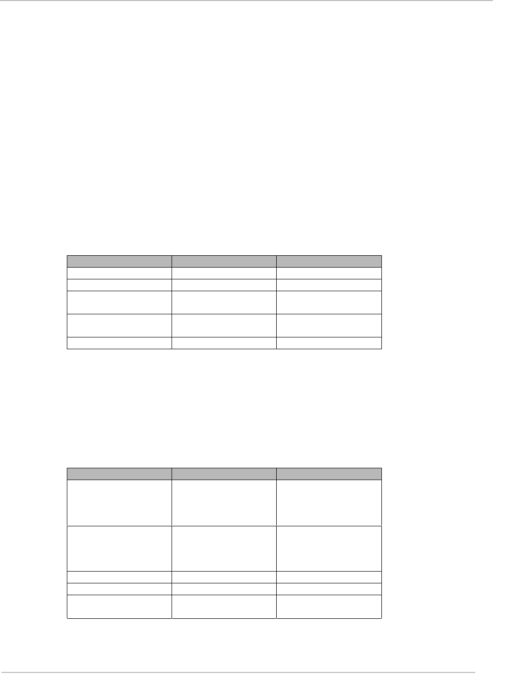
Device Name Firmware Version
RI-RU1-001-00 TBD
Regulatory, safety and warranty notices that must be followed are
provided in Chapter 4.
Conventions
The following pictograms and designations are used in the operating instructions:
WARNING:
A WARNING IS USED WHERE CARE MUST BE
TAKEN, OR A CERTAIN PROCEDURE MUST BE
FOLLOWED, IN ORDER TO PREVENT INJURY OR
HARM TO YOUR HEALTH.
CAUTION:
This indicates information on conditions, which must be
met, or a procedure, which must be followed, which if not
needed could cause permanent damage to the system.
Note:
Indicates conditions, which must be met, or procedures which must
be followed, to ensure proper functioning.
Information:
Indicates conditions or procedures that should be followed to ensure
proper functioning of the system.
Preface

August 2001 Series 7000 Reader Reference Guide
4
Draft Document
FCC ID: A92RU1001A
If You Need Assistance
Application Centers are located in Europe, North and South America, the Far East and
Australia to provide direct engineering support.
For more information, please contact your nearest TIRIS Sales and Application Center.
The contact addresses can be found on our home page: http://www.tiris.com.
Numerical Representations
Unless otherwise noted, numbers are represented as decimal.
Hexadecimal numbers are represented with the suffix 16, e.g. A5F116
Binary numbers are represented with the suffix 2, e.g. 10112
Byte representations: the least significant bit (lsb) is bit 0 and the most significant bit
(msb) is bit 7.

August 2001 Series 7000 Reader Reference Guide
5
Draft Document
FCC ID: A92RU1001A
Document Overview
Chapter 1: Introduction..............................................................................................................6
1.1 Description..........................................................................................................7
Programming Interface...........................................................................................7
1.2................................................................. Summary of Chapters and Appendixes
...................................................................................................................................8
Chapter 2: Frame Request/Response Protocol.......................................................................9
2.1 General Specification .......................................................................................10
Specification .........................................................................................................10
DB-25 Connector Function...................................................................................11
DB-25 Pin Assignments........................................................................................11
Pin Assignment Details.........................................................................................11
Chapter 3: Message Structure.................................................................................................14
3.1 Reader Panel Configurations ...........................................................................15
RI-RU1-001A-00 Front Panel Configuration.........................................................15
RI-RU1-001A-00 Rear Panel Configuration .........................................................15
Typical Reader Installation Steps............................................................................16
Connect External Antennas..................................................................................16
Placing the Antennas............................................................................................16
Connecting to a PC Serial Port or RS-232...........................................................17
Connecting to a DC Source..................................................................................17
Testing the Reader Set-up ...................................................................................17
Aligning the Antenna ............................................................................................19
Writing Information to Tag-it UHF inlay Inlays......................................................19
Chapter 4: Service and Error Codes.......................................................................................21
4.1 FCC Part 15 Compliance..................................................................................22
Radio Frequency (RF) Exposure..........................................................................22
4.2 ETSI Conformity ...............................................................................................23
4.3 CE Conformity ..................................................................................................23
4.4 Environmental Requirements ...........................................................................23
4.5 Warranty and Liability.......................................................................................24
Appendix A: RF Exposure Labeling Requirements................................................................25
RF Exposure "Caution" Label..................................................................................25
RF Exposure "Caution" Sign ...................................................................................26

August 2001 Series 7000 Reader Reference Guide
6
Draft Document
FCC ID: A92RU1001A
Introduction
Topic Page
1.1 Description..........................................................................................................7
Programming Interface...........................................................................................7
1.2 Summary of Chapters and Appendixes..............................................................8
Chapter 1
August 2001 Series 7000 Reader Reference Guide
7
Draft Document
FCC ID: A92RU1001A
1.1 Description
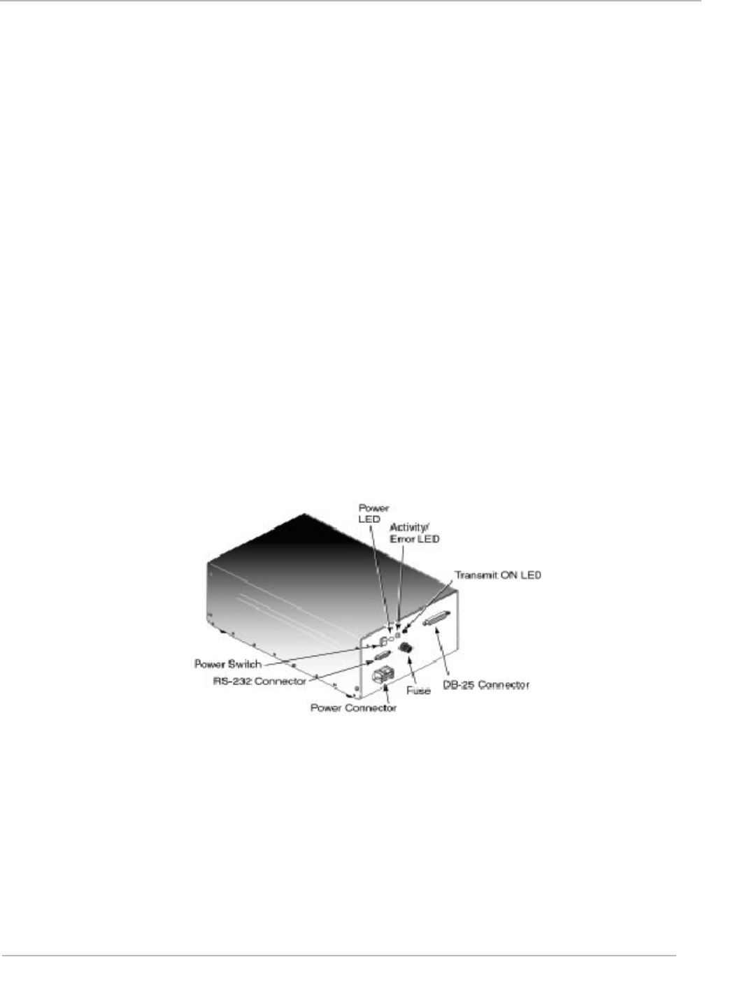
This document describes the features and operational characteristics of the RI-RU1-001A-00 Series
7000 Ultra-High Frequency Reader as shown in Figure 1. The Series 7000 Reader operates at a
frequency of 915MHZ and is compatible with Tag-it UHF inlays and tags.
The reader provides nine coaxial connectors for supporting up to nine external antennas. Each
antenna plugs into its own connector on the rear panel of the reader. The reader can be configured
to read inlays in the following modes:
• Collective or selective data to be read from a single inlay.
• Collective or selective data to be read from multiple inlays without requiring sorting or unpacking.
• Classes of inlays to be filtered according to user-defined criteria.
This technology employs an interrogation feature that enables applications to uniquely identify all
inlays in the scan field, without misidentification. It also uses a protocol that maintains a uniform per-
inlay scan time, regardless of the number of inlays in the scan field. The protocol provides a flexible
software application interface that can be customized to the specific needs of particular industries or
applications. This reference guide provides the details that are necessary to properly interface and
use the reader as a part of an integrated system.
Figure 1: RI-RU1-001A-00 UHF Reader
Programming Interface
The Series 7000 Reader is designed to operate as a part of a host-based reader system, which
essentially relegates the reader to be a slave to the host. Host-to-Reader serial communications are
accomplished within data packets, which occurs at RS-232 levels using 57,600. By definition, the
host is always the primary station and initiates all communication sequences.

August 2001 Series 7000 Reader Reference Guide
8
Draft Document
FCC ID: A92RU1001A
1.2 Summary of Chapters and Appendixes
Chapter 1: Introduction
Chapter 2: Hardware Description
Chapter 3: Reader Operation
Chapter 4: Regulatory and Warning Notices
Appendix A: RF Exposure Labeling Requirements

9
FCC ID: A92RU1001A
Hardware Description
Topic Page
2.1 General Specification .......................................................................................10
Specification .........................................................................................................10
DB-25 Connector Function...................................................................................11
DB-25 Pin Assignments........................................................................................11
Pin Assignment Details.........................................................................................11
Chapter 2
August 2001 Series 7000 Reader Reference Guide
10
Draft Document
FCC ID: A92RU1001A
2.1 General Specification
This chapter describes the electrical and mechanical specifications of the Series 7000 RI-RU1-001A-
00 reader. Operating at a frequency of 915 MHz, this low profile device is designed to be easily
integrated into many logistics management systems and supports as many as nine antennas through
nine separate coaxial connectors. All reader I/O is accomplished through the use of a DB-9F
connector, to include all communication, which is asynchronous RS232 as controlled by a host
system. The reader also has a DB-25 connector that is intended for general diagnostic functions.
Specification
Operating Frequency: 915 MHz
LEDs: One Power ON LED, one Transmit ON LED, and one Activity/Error LED
Communication Method: RS-232
Serial Transmission Rate: Up to 57,600 bps
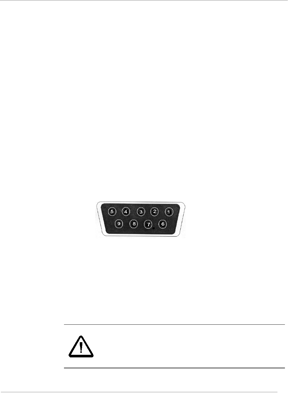
Connectors: One Female DB-9F for RS-232 communications
One DB-25 for diagnostic use
DB9F Pin Assignments: Pin 1 _ Not used
Pin 2 - Transmit Data (Input)
Pin 3 - Receive Data (Output)
Pin 4 - Internally connected to Pin 6
Pin 5 - Protective Ground
Pin 6 - Internally connected to Pin 4
Pin 7 - Internally connected to Pin 8
Pin 8 - Internally connected to Pin 7
Pin 9 - Protective Ground
Power Input: 12 V, 3 Amps
RF Output Power: 1 Watt
Power Consumption: 15 watts
Ambient Operating
Temperature: 0° to 50° C (32° to 122° F)
Maximum Serial
Cable Length: 10 meters (30 Feet)
Dimensions: 36 cm x 20 cm x 11 cm
(14 in x 8 in x 4.5 in)
Weight: 3 Kg (7 lbs.)
CAUTION:
The Series 7000 reader is an intentional radiator, and when
integrated, the integrator is subject to meeting FCC Part
15, Subpart C, and similar tenets under European
Standard EN 300330.
August 2001 Series 7000 Reader Reference Guide
11
Draft Document
FCC ID: A92RU1001A
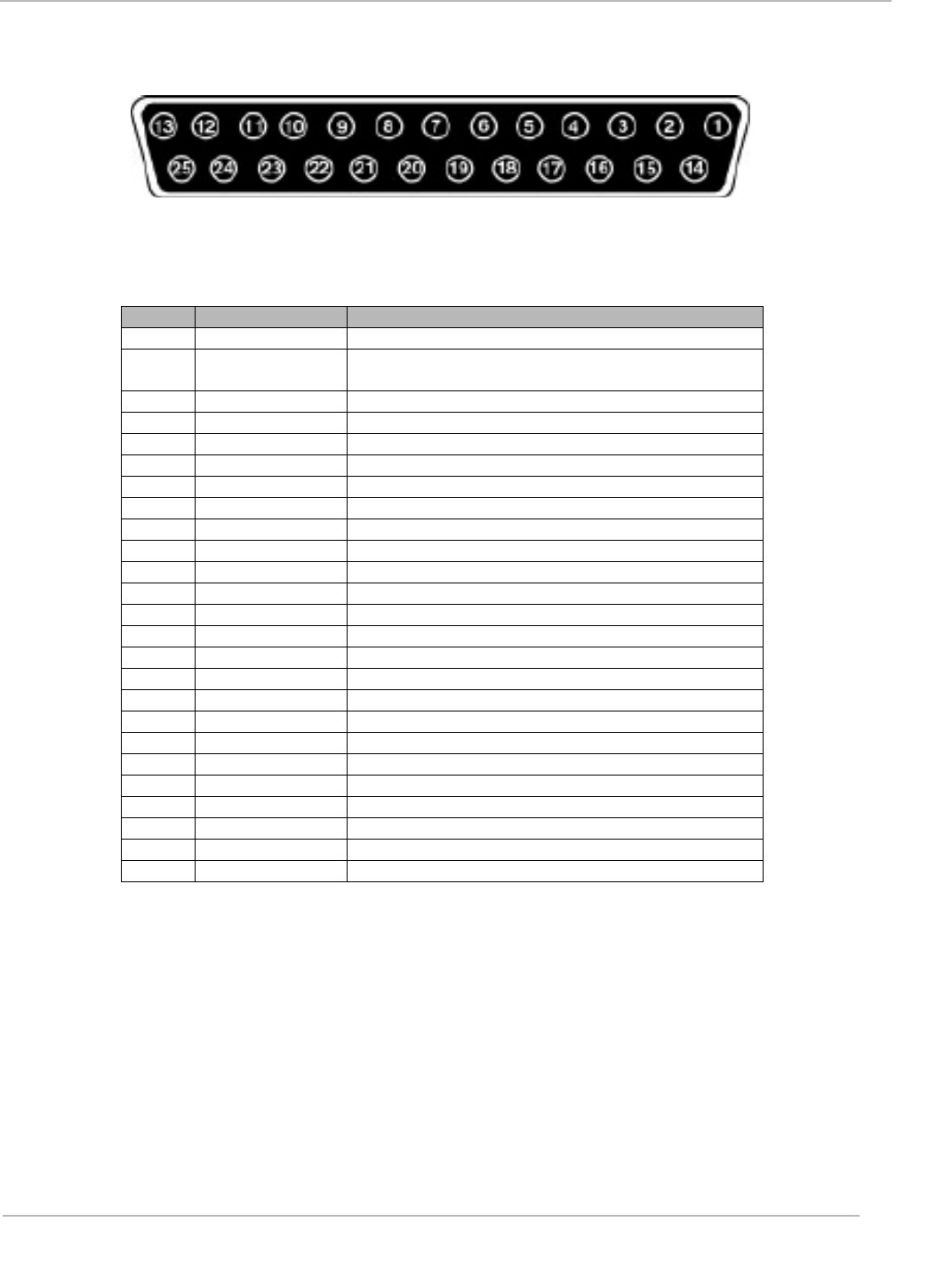
DB-25 Connector Function
DB-25 Pin Assignments
Pin Name Function
1GND Ground
2BUFCOMP Digital test signal: output of receiver
comparator
3GND Ground
4PER_IN2 Peripheral input bit 2
5PER_IN0 Peripheral input bit 0
6PER_OUT6 Peripheral output bit 6
7PER_OUT4 Peripheral output bit 4
8TX_ASEL5 Transmit antenna select bit 5
9TX_ASEL3 Transmit antenna select bit 3
10 TX_ASEL1 Transmit antenna select bit 1
11 RX_ASEL5 Receive antenna select bit 5
12 RX_ASEL3 Receive antenna select bit 3
13 RX_ASEL1 Receive antenna select bit 1
14 VCC +5 volts
15 BUFCOMPIN Analog test signal: input to receiver comparator
16 PER_I Peripheral input
17 PER_I Peripheral input
18 BLAN Digital test signal
19 PER_OU Peripheral output
20 PER_OU Peripheral output
21 TX_ASE Transmit antenna
22 TX_ASE Transmit antenna
23 GN Ground
24 RX_ASE Receive antenna
25 R-ASEL Receive antenna
Pin Assignment Details
Receive Antenna Select Lines
Pins 13, 25, 12, 24, and 11 are the high order bits of the hardware pins that select the receive
antenna. Bit 0 is kept internal to the interrogator. These lines are used to drive external multiplexers
for multi-antenna systems. They are controlled by:
1. Setting up the antenna select table in flash memory (if necessary) using Load Antenna Table
command.
2. Issue the Set Antenna Quantity command.
August 2001 Series 7000 Reader Reference Guide
12
Draft Document
FCC ID: A92RU1001A
3. Default mode automatically cycles through all antennas. The interrogator will freeze at a certain
antenna selection by issuing the Select Receive Antenna command.
Transmit Antenna Select Lines
Pins 10, 22, 9, 21, and 8 are the high order bits of the hardware pins that select the transmit antenna.
Bit 0 is kept internal to the interrogator. These lines are used to drive external multiplexers for multi-
antenna systems. They are controlled by:
1. Setting up the antenna select table in flash memory (if necessary) using Load Antenna Table
command.
2. Issue the Set Antenna Quantity command.
3. Default mode automatically cycles through all antennas. The interrogator will freeze at a certain
antenna selection by issuing the Select Transmit Antenna command.
Peripheral Inputs
Pins 5, 17, 4, and 16 are TTL level inputs that can be read with the Read Peripheral Inputs command.
Description Minimum Maximum
Input - High Level 2.0 V VCC*
Input - Low Level 0V 0.8V
Input Signal
transition Time - 250nS
Input Leakage
Current -10µA +10µA
Input Capacitance - 10pF
*Note: VCC Min. is 4.75 volts, VCC is nominally 5.0 volts. All voltage values are DC.
Peripheral Outputs
There are 8 peripheral outputs internal to the interrogator. 4 of these are available at the DB-25
connector: pins 20, 7, 19, and 6 can be controlled by setting or resetting bits, 3, 4, 5 and/or 6 of the
command data byte of the Write Peripheral Outputs command. The outputs are compatible with
CMOS levels.
Description Minimum Maximum
High level output
voltage @
IOutputHigh = 1.0 mA,
VCC* Min.
VCC* - 0.5 Volts -
Low level output
voltage @
IOutputHigh = 12.0
mA, VCC* Min.
-.4 Volts
Source current - -1.0 mA
Sink current - 12.0 mA
Output leakage
current -10 µA+10 µA
*Note: VCC Min. is 4.75 volts, VCC is nominally 5.0 volts. All voltages values are DC.
Additional Pin Assignments

August 2001 Series 7000 Reader Reference Guide
13
Draft Document
FCC ID: A92RU1001A
Buffered Comparator Input (BUFCOMPIN)
This is the analog output of the RF receiver. The pin must remain unconnected, or deterioration of
read capability will occur.
Buffered Comparator (BUFCOMP)
This is the digitized output of the RF receiver.
Receiver blanking signal (BLANK)
When low, the microcontroller is ignoring the output from the RF receiver.
VCC
This is the 5.0 V regulated power for the interrogator. It should only be used as a reference. Current
drawn in excess of 50 mA may cause the system to shut down.

14
FCC ID: A92RU1001A
Reader Operation
This chapter provides configuration information for the RI-RU1-001A-00 reader when used
with the appropriate inlay(s). The reader provides the connectors and LEDs described in the
following sections.
Topic Page
3.1 Reader Panel Configurations ...........................................................................15
RI-RU1-001A-00 Front Panel Configuration.........................................................15
RI-RU1-001A-00 Rear Panel Configuration .........................................................15
Typical Reader Installation Steps............................................................................16
Connect External Antennas..................................................................................16
Placing the Antennas............................................................................................16
Connecting to a PC Serial Port or RS-232...........................................................17
Connecting to a DC Source..................................................................................17
Testing the Reader Set-up ...................................................................................17
Aligning the Antenna ............................................................................................19
Writing Information to Tag-it UHF inlay Inlays......................................................19
Chapter 3
August 2001 Series 7000 Reader Reference Guide
15
Draft Document
FCC ID: A92RU1001A
3.1 Reader Panel Configurations
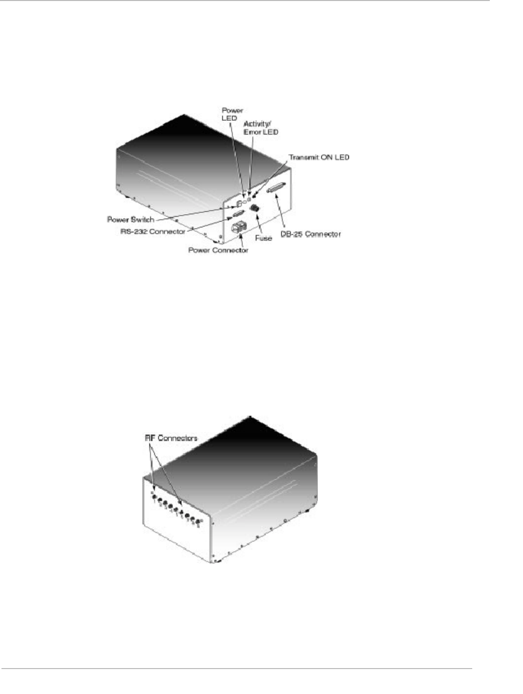
RI-RU1-001A-00 Front Panel Configuration
The reader front panel has an On/Off switch. In the ON (up) position, the reader is turned on. The red
Power ON LED should go ON, indicating that the reader is receiving power. In the OFF (down)
position, the reader is turned off and not receiving power, even if connected to a power outlet.
The front panel also contains three connectors. The lower connector is a DC power receptacle. The
middle connector is the 9-pin RS-232 port. The RS-232 serial port connector allows the reader to
communicate with a personal computer.
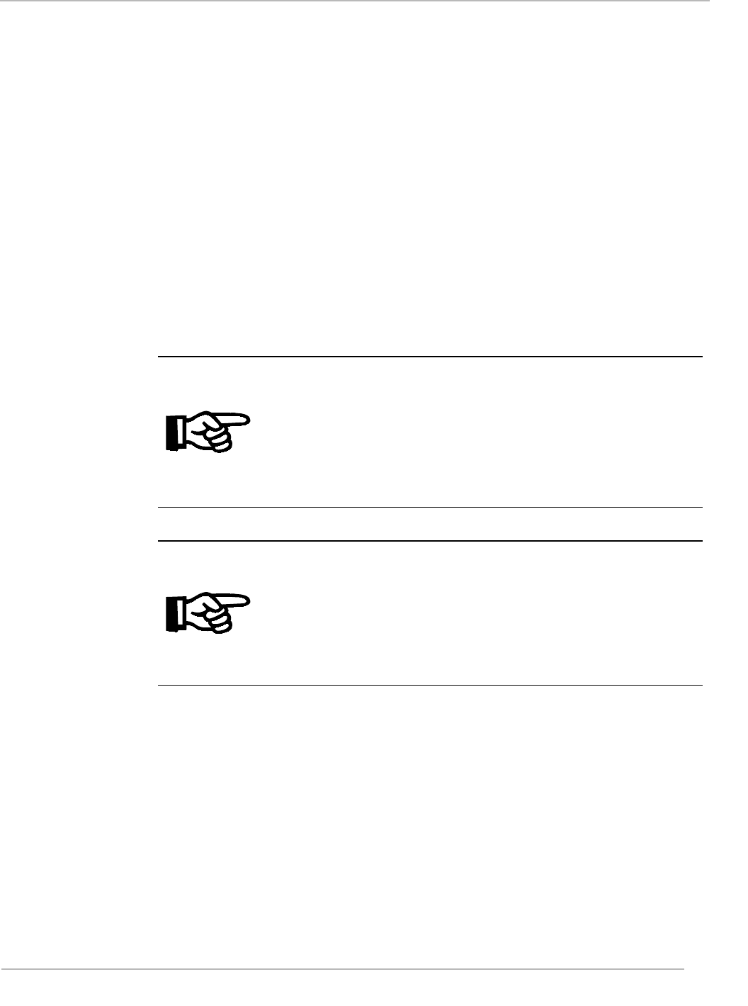
RI-RU1-001A-00 Rear Panel Configuration
The rear panel has nine coaxial connectors for connecting external antennas. Note that the reader
can also operate with fewer than nine antennas.

August 2001 Series 7000 Reader Reference Guide
16
Draft Document
FCC ID: A92RU1001A
Typical Reader Installation Steps
The reader installation consists of the following typical steps:
1. Position the reader — locate near desired antenna locations.
2. Connect external antennas
3. Place the antenna for optimum read/write operation
4. Connect the reader to PC serial port or RS-232
5. Connecting to a DC source
6. Configure the reader
7. Align the antenna
Connect External Antennas
The rear panel provides nine coaxial antenna connectors. Each connector accommodates a single
external antenna. The RI-RU1-001A-00 can be used with fewer than nine antennas. Install antennas
sequentially, starting with the left-most connector.
Placing the Antennas
Antenna placement is critical to ensure information is written to and read from inlays accurately.
Observe the following guidelines when placing the antenna:
Locate the antenna away from metal objects, microwave ovens, and other devices that may induce
radio frequency interference. In addition, make sure there are no metallic surfaces between, or in
relative proximity to, the reader and inlay.
When reading, the antenna should be placed no more than 84 inches from the objects bearing inlays.
When writing, the antenna should be no more than 24 inches from objects bearing the inlay.
WARNING:
To meet FCC RF Exposure compliance, operator(s)
should not be closer than 9 inches to the transmitting
antenna. See RF Exposure precautions in Chapter 4.
The front of the antenna must be free of obstructions. Otherwise, information may not be written to
and read from inlays accurately.

August 2001 Series 7000 Reader Reference Guide
17
Draft Document
FCC ID: A92RU1001A
CAUTION:
Antennas must be labled indicating minimum seperation
distance per FCC RF Exposure requirements. If the
information on the label is not clearly visible, a sign with
the same information must be posted within 36” of the
antenna. See last section of this manual.
Connecting to a PC Serial Port or RS-232
The reader has a 9-pin female RS-232 connector that connects to a serial port or RS-232 connector
on an IBM or compatible personal computer. The serial port can operate up to 57,600 bps. To make
this connection, you need:
• An appropriately configured serial cable.
• One of the following adapters, if your computer's serial port does not have a 9-pin connector:
- A 15-pin to 9-pin adapter, if your computer has a 15-pin serial port connector.
- A 25-pin to 9-pin adapter, if your computer has a 25-pin serial port connector.
• Use the following procedure to connect the reader to your computer's serial port.
1. Attach the male connector on the serial cable to the 9-pin serial connector on the reader's front
panel.
2. Connect the other end of the cable to your computer's serial port. Use an adapter, if
appropriate, to make this connection.
Connecting to a DC Source
The following procedure describes how to connect the reader to an AC Outlet.
1. Verify that the On/Off switch on the reader front panel is in the OFF (down) position.
2. Connect a DC power supply to the DC receptacle on the reader front panel. The DC power
supply must provide between 8-35 VDC at 2 AMPs and must have an AMP connector, with part
number 1-480698-0, and socket terminations.
3. Set the On/Off switch to the ON (up) position. The Power ON LED light will illuminate.
Testing the Reader Set-up
The following procedure will verify that the RS-232 link between the reader and the computer is
functioning correctly, and test the full functionality (read, write, multiread) of the reader in the
surrounding environment.
1. Insert the supplied Development and Demo Tools, Disk 1, into an available floppy disk drive.
2. Open the "My Computer" icon on the desktop.
3. Open the floppy disk drive (typically A:).

August 2001 Series 7000 Reader Reference Guide
18
Draft Document
FCC ID: A92RU1001A
4. Run the application "Install.exe"
5. Installshield will launch and guide you through the installation of the Demo Tools onto your
computer.
6. Turn on the reader and ensure that the antennas are connected to the reader. Connect each
antenna from left to right.
7. Select the "Test Tool" icon in the tools folder from the start menu.
8. If the reader is attached to COM1 or COM2, it will be recognized by the application automatically.
In the application dialog, you will see the text "found reader (rev XX.XX) on COMX".
9. If the reader is attached to COM3 or COM4, the application will not recognize the reader
automatically. In the application dialog, you will see the text "Can't find Reader, use Manual
Connect." Select the appropriate COM PORT by pressing the down arrow in the "Reader <->
Host" frame. Hit the connect button. You should see the text message "Connect: found reader
(revision XX.XX) on COMX".
10. Look for the text "Reader type = XXXX" in the application dialog. If "XXXX" is not "RI-RU1-001A-
00", select "RI-RU1-001A-00" from the Reader menu of the Test Tool application.
11. Look for the text "Mode = ..." in the application dialog. If the mode is not "Basic Function Test",
select "Basic Function Test" from the Mode menu of the Test Tool application.
12. There are three tests you must run in order to confirm that the reader is working correctly. These
are "Read Test", "List Test", and "Write Test".
13. Select "Antenna 1" button at the top of the Reader Test window. Hold a inlay in front of the
antenna while ensuring that your hand is not between the antenna and inlay, or covering the inlay
antenna.
14. Position an object with a inlay within 84 inches of the antenna.
15. Click the "Read Test" button. You should see the text "- Check Read: PASS _" appear in the Test
Results box. If the test fails, follow the instructions given by the application.
16. Remove all inlays from around the antenna and click the "List Test" button. Wait two seconds. If
the test is successful, you should see the following text appear in the Test Results box.
"- Check List _"
"List Start: OK"
"List Stop: OK"
"List Report: OK"
"Found 0 inlays:"
"Place 1 inlay in the field and run test again."
17. Each List Test is composed of three commands given to the reader. If the test is successful, all
these tests should say "OK" after the test name. The application will ask you to repeat the List
Test with 1) A single inlay, and 2) two inlays in front of the antenna. The test is complete when
the application successfully detects two inlays.
18. The Write Test requires a write - capable inlay. Place the inlay within 24 inches of the antenna.
19. Click on the Write Test button and observe the results in the Test Results box. If the test passes,
you will see:

August 2001 Series 7000 Reader Reference Guide
19
Draft Document
FCC ID: A92RU1001A
"- Check Write _"
"Write: OK"
20. If the test fails, follow the instructions given by the application. If you repeatedly get the "Move
inlay closer to antenna" instruction, ensure the inlay is directly over the antenna and there are no
objects between the antenna and inlay.
21. For each antenna that is connected to the reader, repeat steps 13-20 for that antenna.
22. This completes the reader test.
Aligning the Antenna
After verifying that the reader is operating properly, use the following procedure to align the antenna(s).
Aligning the antenna(s) ensures optimal performance.
1. Connect the reader to COM1 or COM2 and turn the power on.
2. Run the application "Test Tool" in the "Tools" folder in the start menu.
3. From the mode menu, choose "Antenna Alignment".
4. Select the antenna you wish to align with the available antenna buttons. Press the "Go" button.
5. Position an object with a inlay in the "scanning area", the point where you intend to scan.
6. Adjust the antenna until the application indicates it detects a inlay. You can find the complete
scanning field by moving the inlay around. When the application detects a inlay, the window will
flash with the message "Label Found". Press the "GO" button again to stop the alignment test.
7. If you have other antennas connected, you can select the different antennas by using the antenna
buttons on the top of the window.
Writing Information to Tag-it UHF inlay Inlays
Read/write inlays can be written to using the reader. Each bit of memory is write once, read many
(WORM). Meaning after you have written to a specific bit, it is permanent and cannot be overwritten
or erased. To add more data to the inlay you must write to a different bit. Another feature included
with each user-writable word of memory is a Write-Protect bit. This bit allows you to protect an entire
word (16 bits) after any or all of the bits have been written.
1. Start the Demo application as described in the previous section.
2. Position an object with a inlay within 24 inches of the transmitting antenna and double click on its
ID to bring up the inlay dialog.
3. In the Write Protect frame, hit "Query All". Any writable memory location will become editable
(white), while write protected memory locations will stay gray.
4. Move the mouse cursor over a memory location and click within that location to edit it. Enter a
new value and then hit "refresh" or move the cursor to a different memory location and click. The
application will attempt to write the value you specified to the inlay.

August 2001 Series 7000 Reader Reference Guide
20
Draft Document
FCC ID: A92RU1001A
5. The status of the inlay will be displayed in the status box at the lower part of the screen. If the
write was unsuccessful, the value in the memory location will change back to reflect the value
actually stored there.
6. To write protect a memory location, move the cursor to a memory location and click the "Set"
button in the Write Protect section. The memory location will change from a white background to
a gray background to show that it is now write protected.
7. To write to a block of memory locations, use the commands in the block section of the window.
Enter the starting memory location in the "From" window. Enter number of memory locations in
the "Length" window. The ending memory location will be automatically calculated in the "To:"
window. Click the box to the left of the "Write" text and enter the data in the window below the
"Write" command.
8. To write protect the entire block, click the box to the left of the "Write Protect" text.
9. To complete the block write command, select the "Perform" button.
10. To return to the List ID mode, click the "OK" button.

August 2001 Series 7000 Reader Reference Guide
21
FCC ID: A92RU1001A
Regulatory and Warranty Notices
Topic Page
4.1 FCC Part 15 Compliance..................................................................................22
Radio Frequency (RF) Exposure......................................................................22
4.2 ETSI Conformity ...............................................................................................23
4.3 CE Conformity ..................................................................................................23
4.4 Environmental Requirements ...........................................................................23
4.5 Warranty and Liability.......................................................................................24
Chapter 4
August 2001 Series 7000 Reader Reference Guide
22
Draft Document
FCC ID: A92RU1001A
4.1 FCC Part 15 Compliance
This equipment has been tested and found to comply with the limits for a Class B digital
device, pursuant to Part 15 of the FCC Rules. These limits are designed to provide
reasonable protection against harmful interference in a residential installation. This
equipment generates, uses and can radiate radio frequency energy and, if not installed and
used in accordance with the instructions, may cause harmful interference to radio
communications. However, there is no guarantee that interference will not occur in a
particular installation. If this equipment does cause harmful interference to radio or television
reception, which can be determined by turning the equipment off and on, the user is
encouraged to try to correct the interference by one or more of the following measures:
-- Reorient or relocate the receiving antenna.
-- Increase the separation between the equipment and receiver.
-- Connect the equipment into an outlet on a circuit different from that
to which the receiver is connected.
-- Consult the dealer or an experienced radio technician for help.
Note:
This device complies with the limits for a Class B digital device,
pursuant to Part 15. The Class B limits help insure that this device
provides reasonable protection against harmful interference in
residential installations. This equipment generates, uses, and can
radiate radio frequency energy and, if not installed and used in
accordance with the instructions in this manual, may cause
harmful interference to radio communications.
Note:
NO MODIFICATIONS: Modifications to this device shall not be
made without the written consent of Texas Instruments
Incorporated. Unauthorized modifications may void the authority
granted under Federal Communications Commission Rules
permitting the operation of this device.
Radio Frequency (RF) Exposure
In order for this device to comply with FCC-adopted RF exposure limits, precautions must be
taken. To meet the requirements of the FCC’s Maximum Permissible Exposure (MPE)
guidelines, persons should not be closure than 9 inches (23cm) to a transmitting antenna.
For installations where an operator must handle a tag or diagnostic tool closer than 9 inches to
the transmitting antenna, the operator should ensure that the RF antenna is not transmitting
prior to positioning the tag or tool closer than 9 inches to the transmitting antenna, the operator
should ensure that the RF antenna is not transmitting prior to positioning the tag or tool. Once
the operator has positioned the tag or diagnostic tool, and moved away a minimum of 9 inches
from the antenna, the antenna can be re-activated. For all installations labels must be placed

August 2001 Series 7000 Reader Reference Guide
23
Draft Document
FCC ID: A92RU1001A
on individual antennas, or signs must be displayed, indicating “CAUTION: A minimum
separation distance of 9 inches must be maintained between an antenna and persons for
meeting FCC RF Exposure compliance. See Reference Guide for details on operational
requirements.” See Appendix A for site labelling requirements.
For more information on RF Exposure, where incidental exposure may exceed the above
guidelines, please refer to the FCC Office of Engineering and Technology Bulletin 65,
Supplement C, Guidelines for Human Exposure to Radio-frequency Electromagnetic Fields,
available at:
http://www.fcc.gov/oet/info/documents/bulletins/
Disclaimer:
Operation of any radio transmitting equipment, including the reader, may interfere with the
functionality of inadequately protected medical devices. Consult a physician or the
manufacturer of the medical device if you have any questions. Other electronic equipment may
also be subject to interference.
4.2 ETSI Conformity
Any device or system incorporating the Series 7000 reader, in full or in part, may need to
comply with European Standard EN300330. It is the responsibility of each system integrator to
have their complete system tested and to obtain approvals as required from the local authorities
before operating or selling this system.
4.3 CE Conformity
Any device or system incorporating the Series 7000 reader, in full or in part, may need to have a
CE Declaration of Conformity stating that it meets European EMC directive 99/5/EC. This must
be issued by the system integrator or user of such a system prior to marketing or operating it in
the European community.
4.4 Environmental Requirements
The Series 7000 Reader is qualified to meet the following environmental guidelines:
- Life Test: Operating temperature tests in accordance with MIL_STD_810E, Method 501.1,
using the following parameters: 85 degrees C, duration 500 hours.
- High Temperature Storage: Storage temperature tests in accordance with MIL-STD-810E,
method 501.3, Procedure 1 using the following parameters: High temperature 85 degrees C,
500 hours.
- Low Temperature Storage: Storage temperature tests in accordance with MIL-STD-810E,
method 502.3, Procedure 1 using the following parameters: Low temperature -45 degrees
C, 500 hours.
- Humidity Environment: Humidity tests in accordance with MIL-STD-810E, Method 507.3,
procedure III, aggravated screening, using the following humidity parameters: 80 % relative
humidity, non-condensing at 70o C, duration 500 hours.

August 2001 Series 7000 Reader Reference Guide
24
Draft Document
FCC ID: A92RU1001A
- Thermal Shock: Thermal Shock testing in accordance with MIL-STD-810E, Method 503.3,
using the following thermal shock parameters: - 45 to 85 degrees C, 100 cycles duration, 30
minutes per temperature.
- Mechanical Shock Environment: Shock test performed in accordance with MIL-STD-810E,
Method 516.3 using the following parameters: 5 G's at 10 ms, half-sinusoidal wave, 6 axes,
and 3 shocks per axis.
- Vibration Environment: Vibration tests in accordance with MIL-STD-810E, Method 514.4,
using the following parameters: 15 to 500 Hz, 1-g peak, 30 minutes sweep, logarithmic.
4.5 Warranty and Liability
The "General Conditions of Sale and Delivery" of Texas Instruments Incorporated or a TI
subsidiary apply. Warranty and liability claims for defect products, injuries to persons and
property damages are void if they are the result of one or more of the following causes:
! Improper use of the reader module.
! Unauthorized assembly, operation and maintenance of the reader module.
! Operation of the reader modules with defective and/or non-functioning safety and
protective equipment.
! Failure to observe the instructions during transport, storage, assembly, operation,
maintenance and setting up of the reader modules.
! Unauthorized changes to the reader modules.
! Insufficient monitoring of the reader modules' operation or environmental conditions.
! Improperly conducted repairs.
! Catastrophes caused by foreign bodies and acts of God.
August 2001 Series 7000 Reader Reference Guide
25
Draft Document
FCC ID: A92RU1001A
RF Exposure Labeling Requirements
RF Exposure "Caution" Label
Purpose: To meet FCC requirements with regard to RF Exposure, for applications where an individual
antenna is used in conjunction with an S7000 UHF Reader, the antenna must have affixed to it, a label
indicating the minimum separation distance required to meet FCC RF Exposure compliance. See sample
label below.
Label Specification
Size: 1" x 3"
Stock: White, adhesive-backed
Sample Label:
Placement: Label will be placed on antenna radome surface such that it is clearly visible/legible at a distance
of no less than 9 inches from the transmitting antenna, to the operator or any persons who may enter the
vicinity of the antenna.
Exception: If this is not feasible to affix a label to the antenna radome such that it is visible/legible due to the
restraints of a particular application, a "Caution" sign must be posted within 36 inches of the antenna, such
that the verbiage on the sign is clearly visible/legible at a distance no closer than 9 inches from the
transmitting antenna, to any person who may enter the vicinity of the antenna. See RF Exposure "Caution"
Sign Specification.
Appendix A
Caution: A minimum separation distance of 9
inches must be maintained between an antenna
and persons to meet FCC RF Exposure
compliance. See Reference Manual for details on
operational requirements.

August 2001 Series 7000 Reader Reference Guide
26
Draft Document
FCC ID: A92RU1001A
RF Exposure "Caution" Sign
Purpose: To meet FCC requirements with regard to RF Exposure, for applications where a group of RF
antennas is used in conjunction with an S7000 UHF Reader, a sign must be posted indicating the minimum
separation distance required to meet FCC RF Exposure compliance. See sample sign below.
Sign Specification
Size: 5.5" x 8.5"
Specification: One-half sheet of standard white paper.
Sample Sign: 8.5”
5.5”
Placement: In applications that require a group of antennas, a "Caution" sign must be posted within 36
inches of the antennas, such that the verbiage on the sign is clearly legible at a distance no closer than 9
inches from the transmitting antenna, to any person who may enter the vicinity of the antenna.
Caution:
A minimum separation distance of 9 inches
must be maintained between an antenna and
persons to meet FCC RF Exposure
compliance. See Reference Manual for
details on operational requirements.